Article

In-Depth Assessment and Optimized Actuation Method of a Novel Solar-Driven Thermomechanical Actuator via Shape Memory Alloy

by
Ibrahim Khalil Almadani
*,
Ibrahim Sufian Osman
and
Nasir Ghazi Hariri
Department of Mechanical and Energy Engineering, College of Engineering, Imam Abdulrahman Bin Faisal University, P.O. Box 1982, Dammam 31441, Saudi Arabia
*
Author to whom correspondence should be addressed.
Energies 2022, 15(10), 3807; https://doi.org/10.3390/en15103807
Submission received: 20 April 2022 / Revised: 12 May 2022 / Accepted: 18 May 2022 / Published: 22 May 2022
(This article belongs to the Special Issue Advances in Solar Energy and Materials)

Abstract

:
Currently, energy demand is more significant than ever due to population growth and advances in recent technologies. In order to supply more energy while maintaining a healthy environment, renewable energy resources are employed. This paper proposes a novel solar-driven shape memory alloy thermomechanical actuator as an eco-friendly solution for solar thermal applications. The proposed actuator was assessed numerically and experimentally. The numerical tests showed that the designed actuation mechanism’s inner temperature has a minimum variation per day of about 14 °C and a temperature variation of 19 °C for most days of the year, which allows for proper activation and deactivation of the actuator. As for the experimental tests, the presented actuation mechanism achieved a bi-directional force of over 150 N, where the inner temperatures of the actuator were recorded at about 70.5 °C while pushing forces and 28.9 °C while pulling forces. Additionally, a displacement of about 127 mm was achieved as the internal temperature of the actuator reached 70.4 °C. The work presented adds to the body of knowledge of a novel solar-based self-driven actuation mechanism that facilitates various applications for solar thermal systems.

1. Introduction

Advances in modern technologies along with global population growth continuously increase the demand for energy generation day after day; as the energy demand rises, the harmful effects of using fossil fuels, such as global warming and greenhouse emissions, are magnified. The Kingdom of Saudi Arabia (KSA) reported an energy consumption of 299.2 terawatt-hours (TWh) in 2018, where it aims to offer at least half of its generated electricity using renewable energy technologies by 2030, of which the energy demand is expected to reach about 365.4 TWh [1,2,3]. In order to accommodate the increase in energy demand while reducing the negative effect of energy production via fossil fuels, renewable energy such as solar, wind, and biomass are mainly sustainable solutions [4]. Solar energy is an inspiring form of renewable energy due to its availability, accessibility, and cost. Underpinning the facts mentioned, KSA initiated many recent projects in order to harvest solar energy [5,6,7]. In general, there are three categories into which solar energy can be divided: photovoltaics (PV), thermal, and photovoltaic/thermal (PVT), where each category has its pros and cons [8,9]. For example, PV directly transforms solar energy into electrical energy; however, Si-based PV has a comparatively low efficiency depending on the location, while PVT has high efficiency. Nonetheless, PVT has a high cost compared to other solar energy harvesting methods [4,10]. Thermal solar energy collectors have a significantly higher efficiency than PV solar and are relatively inexpensive. This has led to many applications such as space and water heating in addition to desalination [11,12] technologies. At the same time, thermal solar energy can be utilized to generate adequate mechanical energy by controlling the heat of thermomechanical materials such as shape memory alloy (SMA) [13].
SMA is a genre of smart material discovered in 1941 by Arne Ölander [14]. SMA can be fabricated at the desired shape at high temperatures; after that, SMA can be easily deformed due to a change in stress or temperature, as its temperature drops below a specific temperature, known as the martensite finish temperature (Mf), and regains its desired shape due to a produced force as it reaches a particular temperature, known as the austenite finish temperature (Af) [15]. Deformation occurs due to the unique thermomechanical properties of the SMA, leading to the development of recovery forces to regain its desired shape, a phenomenon known as the shape memory effect (SME) [16]. There are many types of SMA, such as Cu-Zn, Cu-Al, and Ni-Ti, depending on the chemical compound of the SMA, where the properties of SMA can be illustrated in hysteresis diagrams showing its behavior under different applied conditions [17]. NiTi (also known as NiTiNOL) is the most common type of SMA since it has a wide range of activation temperatures, is durable, and is inexpensive [18]. SMAs have many recent applications in different disciplines such as biomedical, aerospace, civil, and mechanical engineering [19,20,21].
Jani et al. [22] reviewed SMA research and applications. The performed literature search showed that the publications regarding SMA were mostly in material science, engineering, physics and astronomy, medical and health sciences, and other applied science fields. As for recently granted patents regarding SMA and its advanced technologies, the leading sectors were biomedical, aerospace, robotics, automotive, and other applications by 60.98%, 4.84%, 3.26%, 2.3%, and 28.62%, respectively.
Patra et al. [23] carried out a study to investigate the elasticity behavior of NiTiNOL wires under different stresses to evaluate the variation in strain and hysteresis. The result of the carried experiment showed that the SMA wire understudy entered a hysteresis loop due to the fact that although the applied stress surpassed the loading curve, the SMA managed to regain its predefined shape. Additionally, the study showed that the loading and unloading behaviors of the SMA wire were divergent, in which the author owed this to an accumulation in the strain energy.
One of the most popular usages of SMA is as an actuator, where the SMA provides the actuation role in a dynamic system [24]. Many researchers have taken an interest in reviewing and summarizing the recent developments of an SMA-based actuator, where some researchers observed over 100 novel designs for SMA-based actuators [22]. SMA-based actuators can be found in fields such as aerospace [24], robotics [25,26], automotive [27], biomedical [28], and mechanical systems [29]. Additionally, SMA-based actuators have recently been used in many solar energy systems applications, for example, cleaning [30], and tracking [31] methods. The SMA-based actuators have attracted interest of the researchers due to their smart, unique properties and low production cost [29,32,33]; however, they have mainly two disadvantages: they operate at low speed and have non-linear behavior [32]. SMA-based actuators can be divided into three main types: linear, bending, and rotational SMA-based actuators [19,26,34]. Furthermore, to design the SMA-based actuators, studying the SMA’s characteristics should first be considered, estimating the required force and displacement, and optimizing the necessary displacement and force under the characteristics of the particular SMA [21,35,36,37].
Formentini and Lenci [38] have presented a design for a panel actuated by an SMA-wire-based actuator that can be used to improve the ventilation of a building. The proposed SMA-based actuator opens the panel during summer, which allows the natural air to enter the cavity. In contrast, the actuator closes the panel in the winter, acting as thermal insulation. The outcomes showed that the device could operate properly word-widely by implementing the appropriate SMA material composition for each climate zone to archive the device’s required activation and deactivating temperature.
Copaci et al. [37] devolved a novel fixable SMA-based actuator that can be used in advanced robotics. The developed actuator provides flexible motion in wearable robots. The presented SMA characteristics have concluded that the SMA is an ideal choice in this application; however, some control strategies should be considered. In the study, many prototypes have been built to demonstrate the effectiveness offered by these flexible smart actuators.
Riad et al. [31] built a numerical study for a novel SMA-based sun tracker. The thermomechanical actuator was designed to passively operate by taking the sun’s thermal energy and releasing it to the ambient for the activation and deactivation of the system. It has been concluded by the study that the sun tracker can increase the energy production of the PV module by about 39%.
Hariri [39] carried out a recent study to present a novel design for a dust mitigation technology solution. The presented work utilizes the thermomechanical property that exists in the SMA wires in order to clean PV modules by taking the thermal energy from the unwanted heat rejected by the PV modules. The results showed the effectiveness of the presented technology solution under an indoor experiment using a sun simulator, where the back surface of the PV module reached about 60 °C, which allowed the thermomechanical system to convert the rejected heat into effective mechanical motion.
SMA-based actuators can be activated using joule heating, external active heating/cooling, and external passive heating/cooling [26]. Furthermore, a proposed method in this study uses a solar heat collector (SHC) to activate the SMA-based actuators. SHC is a special device that can absorb the thermal energy provided by the sun and use it in this form or transform it into another form of energy [40]. The use of thermal energy given by the sun has received the attention of many researchers since it is considerably higher than using photovoltaic (PV) energy provided by the sun; some researchers concluded that the available commercial PV systems have efficiency in the range of 15–20%, while the solar thermal systems have efficiency in the range of 34–87% [41,42]. SHC can be utilized in many applications such as domestic or industrial heating/cooling, water desalination, and storage systems [42,43,44]. In order to design an SHC, three main criteria should be considered: technical, cost-effectiveness, and environmental criteria standards [42,45,46]. Moreover, the efficiency of SHC can be affected via multiple factors such as the absorber and collector materials and characteristics and the used fluid inside the SHC [47,48,49].
The proposed work adds to the body of knowledge a comprehensive numerical and experimental assessment and analyses of a solar-driven SMA thermomechanical actuator, highlighting the proposed actuator’s promising mechanical and thermal feasibility. The present work offers an actuation mechanism suitable for solar thermal systems and applications, such as cleaning, tracking, and overheating protection systems. The state-of-the-art SMA thermomechanical solar-driven actuator is self-driven without either human interaction or electrical energy inputs, making the suggested actuation mechanism a unique eco-friendly solution for many solar thermal applications.

2. Materials and Methods

This research effort is aimed at presenting a design of a solar-driven SMA thermomechanical actuator. The basic conceptual design of the linear actuator is illustrated in Figure 1, where the main parts of the thermomechanical SMA actuator are shown. The presented novel design utilizes the SME that exists in NiTiNOL springs to give an actuation mechanism via absorbing and releasing the natural solar thermal energy by using an SHC. The SHC works when it is exposed to sun solar radiation from sunrise until sunset, where the solar radiation is absorbed by the SHC, producing a greenhouse effect inside its body. Therefore, the SHC acts as the activation key in this design, where the NiTINOL springs gain thermal energy via the SHC, where they are activated, while when they lose this thermal energy via the SHC, they are deactivated. Additionally, the actuator is meant to be a piston-based actuator with a bias load that can reorient the NiTiNOL springs to their original shape when they are deactivated.
The solar-driven thermomechanical SMA actuator operates passively using thermal solar energy. In addition, the actuator’s actuation mechanism includes two phases: day and night, as shown in Figure 2. During the daytime, the NiTiNOL springs gain the solar thermal energy by the SHC and are activated, which contracts the NiTiNOL springs, lifting the bias load, and the rod produces a push force. Conversely, when the NiTiNOL springs lose the solar thermal energy to the ambient and are deactivated at night, the NiTiNOL springs re-elongate, the bias load falls, and the rod produces a pull force.

2.1. Solar-Driven Thermomechanical SMA Actuator Design

The solar-driven thermomechanical SMA actuator design has been carried out using computer-aided design (CAD) software, as shown in Figure 3. The designed actuator functions as a piston-based actuator, where the piston is in between the bias load and SMA (NiTiNOL) springs. The actuator transmits the forces through a rod that passes through the linear bearings located inside the cover of the actuator’s SHC. Additionally, the SHC is considered a central part of the actuator that provides the necessary solar energy to the NiTiNOL springs. As the heat collectors change in size and shape, all components inside the heat collector change accordingly.
The detailed actuation cycle includes four main phases; where at the first phase, the NiTiNOL springs are contracted and under the austenite starting temperature, while the bias load is off its home position. Second, the NiTiNOL springs are contracted until they achieve the austenite finish temperature, where the bias load is at a maximum height. Third, the NiTiNOL springs release the thermal energy until the springs reach the martensite start temperature and the NiTiNOL springs are re-elongated, and then the bias load starts to return to its home position. Finally, the NiTiNOL springs fully stretch, and the bias load reaches its home position or its minimum height.

2.2. Solar-Driven Thermomechanical SMA Actuator Fabrication

The actual solar-driven thermomechanical SMA actuator model has been fabricated, as seen in Figure 4, where all the essential parts are highlighted. The solar-driven thermomechanical SMA actuator has three main outer surfaces: one acrylic surface and two aluminum surfaces.
The acrylic surface has been chosen to allow the solar irradiance to pass through the SHC into the springs smoothly, while the aluminum surfaces have been chosen to support the structure of the SHC from the axial forces and to help to reflect the solar irradiance back to the NiTiNOL springs, which would help the thermal heating process inside the actuator. The aluminum surfaces can be replaced with metal such as tungsten and silver or any metal that has high reflectivity to increase the solar radiation that falls into the SMA, and high thermal resistance to reduce the amount of heat dissipation.

2.3. Force and Displacement Assessment Platform

In order to reach the desired outcomes of this work, analytical force analysis and a displacement assessment under different loads must be carried out. In this regard, a force and displacement assessment platform are designed with the aim of ensuring the output force from the actuator and the produced displacement from it. The platform has been designed to investigate the NiTiNOL springs’ maximum force, NiTiNOL springs’ maximum deflection under different loads, cold NiTiNOL spring constant, hot NiTiNOL spring constant, and the life expectancy of the NiTiNOL springs. In addition to that, the force and displacement offered by the designed actuator have been investigated.

2.3.1. Mechanical Setup for the Assessment Platform

The NiTiNOL springs assessment platform’s mechanical setup is designed to have dual use. The platform consists of fixed parts and removable extensions. The fixed parts of the platform are a base holder, a beam with two vertical passways, and a spring bed, as shown in Figure 5a. As for the removable extensions of the platform, there are two parts: the encoder unit and load cell unit, as shown in Figure 5b,c. The removable extensions enable the platform to act for both force and displacement assessments. In addition, having removable attachments help to facilitate the adjustments in the distance between the spring bed and the attachment. The load cell unit is installed in the beam for the force assessment test, and the NiTiNOL spring is connected between the spring bed and the load cell unit. As for the displacement assessment test, the encoder unit is installed in the beam, and the NiTiNOL spring is connected between the spring bed and the encoder unit.
Additionally, another assessment platform has been designed to investigate the forces and the displacement that the solar-driven thermomechanical SMA actuator would produce. This assessment platform is shown in Figure 5d, where the platform is chosen to be horizontal in this case.

2.3.2. Electrical Setup

As for the software setup of the force and displacement assessment test, for the force assessment test, an Arduino Nano is used to collect the data extracted from the load cell. As for the displacement assessment test, a myDAQ unit is used to read the data extracted from the encoder. The setup is powered via a power supply, and a MOSFET is used with a high pass filter as the motor driver to pass current to the NiTiNOL springs from the power supply. Figure 6 shows an overview of the electrical schematic diagram for the force and displacement assessment tests.

2.3.3. Experimental Criteria

The first test measures the NiTiNOL springs’ maximum force; in order to do so, a step command is incrementally increased to test the maximum force exerted from the NiTiNOL spring. In the second test, NiTiNOL springs’ maximum deflection during the phase change from austenite to martensite under different loads is measured by attaching a calibrated weight to the NiTiNOL springs after the current is passed through the NiTiNOL spring, which causes a Joule heating effect, leading the spring to shrink and thus rotating of the encoder nob. In the third test, the spring constant is measured via applying different loads to a spring and measuring the change in its length; after that, the spring constant is calculated via the spring force formula. The fourth test, the life expectancy of the NiTiNOL springs, is measured using both a displacement test and force test, running multiple repeatable square wave commands in order to test the lifecycle upon which the life expectancy can be estimated. Finally, different force and displacement tests have been carried out on the whole thermomechanical actuator using an external heat source.

2.3.4. Software Setup

The data gained from the NiTiNOL spring’s assessment tests are analyzed and used as the feedback signal in a gain-scheduling PID controller. In order to determine the gain-scheduling values, where different gains were tested for each value, the different gains were assigned for each value depending on its response. The PID controller is applied to different commands and compares the extracted feedback signal to the commands given in order to manipulate the NiTiNOL spring behavior to follow a desired input, enabling different displacement and force commands for the lifecycle tests. The PID commands used to manipulate the NiTiNOL springs are the step, square wave, sine wave, and staircase commands. These various commands ensure the compatibility of the gains determined for the gain scheduling PID controller. Figure 7 demonstrates the functional block diagram of the system, while Figure 8 represents the flow chart of the control scheme.

3. Results and Discussion

In this section, the results of the work conducted will be demonstrated. First, force and displacement assessments were carried out to gather the necessary design criteria in which the solar-driven thermomechanical actuator was designed. After that, the numerical and experimental results of the actuation mechanism are detailed in addition to a simplistic cost analysis of the proposed actuator.

3.1. Force and Displacement Assessment

In the following segment, the force and displacement assessments were carried out, which included NiTiNOL springs’ force calculation in both martensite and austenite phases (hot and cold). In addition, the NiTiNOL springs were tested for maximum deflection. The gathered results facilitated the design of the solar-driven thermomechanical actuator.

3.1.1. Force Analysis

Multiple force assessments were made to establish a solid ground upon which all further force analyses would depend. First, the maximum tensile force produced by the NiTiNOL spring was tested using a gain-scheduling PID controller. After that, many commands were used to test the compatibility and precision of the PID in addition to the behavior of the NiTiNOL spring utilized, where square wave, sinusoidal wave, and staircase wave commands were applied.
Different step commands were applied to test the gain-scheduling PID controller response for various steps, as shown in Figure 9. The characteristics of the step command applied are shown in Table 1. Furthermore, the square wave command was tested in a square wave command cycle ranging from 15% to 80% of the maximum expected force. The square wave command is used in the performance test to ensure that the NiTiNOL spring’s behavior would not differ after a few cycles. The performance test results are shown in Figure 10.
The staircase wave command is more complicated than the square wave command. This command has a rising step every 10 s where the signal was initiated from 0% of the maximum expected force of the NiTiNOL spring; then, the signal starts increasing by 10% for each step until it reaches 100% for the maximum expected force; after that, the signal begins decreasing by 10% for each step until it returns to 0% of the most expected force. This test demonstrated the PID controller’s ability to simulate different linear command values. Figure 11 displays the PID controller response to the staircase wave command using the developed closed-loop force control system. It is noted from the graph that as the command decreases over time, the feedback’s response gradually decelerates. The deceleration can be owed to the drop in temperature difference between the NiTiNOL spring and the ambient temperature, which led to a slower heat dissipation, causing the large deviation shown at the end of the graph.
The sinusoidal wave command is more complicated than the last commands because it is a time-varying non-linear waveform. This command, demonstrated in Figure 12, has a frequency of 0.2 Hz and an amplitude ranging from 15% to 80% of the maximum expected force. The PID controller has shown a high precision in simulating the sinusoidal wave command, proving that the developed PID controller is capable of simulating non-linear waveforms.
The test performed to measure the maximum tensile force for the NiTiNOL springs showed that one spring can carry up to 1.5 kg, which amply a force (F) of 14.7 N according to Equation (1).
F = m × g
where F is the force, m is the mass, and g is the Earth’s gravitational acceleration. Multiple celebrated weights were attached to a NiTiNOL spring, and the change in displacement was recorded. Subsequently, KCN was calculated using Equation (2).
F s = S C × Δ x S C = F s Δ d
where Fs is the Spring force, S C is the spring’s constant, and Δx is the change in displacement. The NiTiNOL spring’s cold spring constant (SCCN) has a non-linear value that follows the equation: SCCN = −49.61 ln(x) + 277.08.
In order to complete one entire cycle, the system must start and end at the same point. To achieve that, the force exerted from the hot NiTiNOL springs (FHN) must be more than or equal to the stroke force and the force required to pull the bias load (FBias), as shown in Equation (3).
F H N = F s t r o k e + F b i a s
As for the second stroke, the force exerted by the bias load must be more than or equal to the stroke force in addition to the force needed to deform the NiTiNOL spring when cold (FCN), as shown in Equation (4).
F b i a s = F s t r o k e + F C N
where FCN is the force of the cold NiTiNOL. The equation shows that the number of the NiTiNOL springs and the bias load depend on each other; thus, a trial-and-error process was conducted in order to calculate the number of springs and the bias load needed to achieve a bidirectional force of 130 N, which came out to be 28 NiTiNOL springs and 28 kg load. Table 2 sums up all force values for the actuation mechanism.

3.1.2. Displacement Assessment

Several displacement assessments were performed in order to simulate how the NiTiNOL springs behave to ensure the project’s success. A similar gain-scheduling PID controller designed for the load assessment is applied with different gains to compensate for the differences. The gain-scheduling PID controller was tested with varying signals of command to test the controller’s competence and the NiTiNOL springs’ behavior. The controller is tested with a step command, a square wave command, and a sinusoidal wave command.
The step commands were only used in the gain calibration phase to demonstrate how the controller behaves under different steady commands. The step commands tested 25%, 50%, 75%, and 100% of the maximum deformation of the wire under an attached load of 500 g. Figure 13 shows the PID gains scheduling controller response to the different command values. Table 3 shows different characteristics for the NiTiNOL spring’s response for the different step commands.
The square wave command is crucial but straightforward since it confirms how the controller follows a differentiating signal. In addition, the square wave command is used to run a lifecycle test, which helped estimate the life expectancy of the NiTiNOL springs. The frequency of the square wave command used is 0.25 Hz, the upper limit of the square wave is 50 mm, and the lower limit is 30 mm, which stands for 70% and 40% of the maximum deformation of the spring under an attached load of 500 g. The number of cycles in this test was 950 cycles; thus, if the actuator is activated once per day, then the actuator is expected to operate for at least 2.6 years based on the highlighted result. Figure 14 shows the controller response with the square wave command, while Figure 15 shows the controller’s response with the square wave command under this lifecycle test.
The sinusoidal wave command is an essential command due to the fact that it is commonly used as a measurement criterion for the performance of different controllers. The sinusoidal wave command is used to test the controller for non-linear commands. The sinusoidal wave command used has a frequency of 0.4 Hz, the upper limit of the sinusoidal wave is 50 mm, and the lower limit is 30 mm, which stands for 70% and 40% of the maximum deformation of the wire under an attached load of 500 g. Figure 16 shows the controller response with the sinusoidal wave command.

3.2. Thermomechanical SMA Actuator

In this division, the numerical, simulation, and experimental results of the solar-driven SMA thermomechanical actuator were detailed, whereas a simplified solution of the proposed system is demonstrated in the numerical results. Afterward, the simulation results deduce the thermal analysis of the solar heat collector employed in order to activate the SMA springs used in the piston-based actuator. After that, the experimental results were demonstrated. Lastly, a simplistic cost analysis is included.

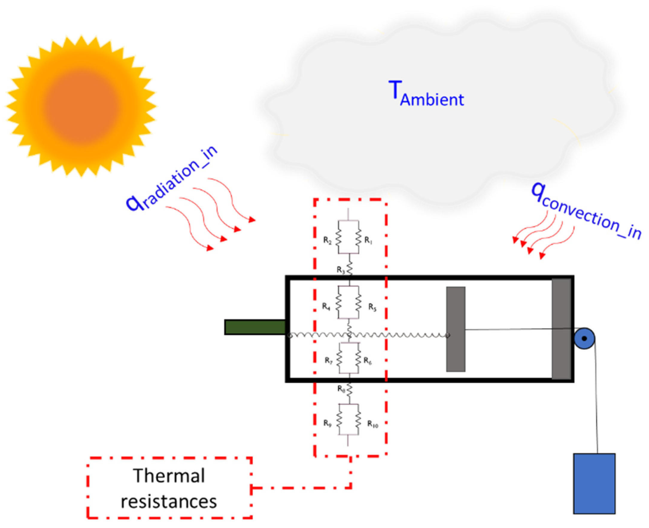
3.2.1. Analytical-Based Model

A simplified one-dimensional (1D) model has been built under the steady-state condition for the SHC in order to understand the thermal behavior of the SMA thermomechanical actuator. The analytical-based model gives a clear indication of the factors that affect the SHC in terms of heat transfer aspect. The 1D model has been created based on taking a cross-section from the SHC and based on the natural heat fluxes and thermal resistance, as Figure 17 demonstrates.
The 1D model mainly utilized the heat transfer general formula and the thermal resistances for the conduction, convection, and radiation heat transferee processes, as shown in Equation (5) below [50].
q = Δ T R ,   R c o n d = L K   ,   R c o n v = 1 h c o n v , R r a d = 1 h r a d
where q is the heat flux, Δ T is the temperature difference, R is the thermal resistance, Rcond is the conduction resistance, L is the distance, K is the thermal conductivity, Rconv is the convection resistance, hconv is the convective heat transfer coefficient, Rrad is the radiation resistance, and hrad is the radiative heat coefficient.
The input thermal energy to the SHC is both convection and radiation heat fluxes, as demonstrated in Figure 17. After these heat fluxes enter the SHC, many thermal resistances aim to absorb this thermal energy. First, the SHC surfaces act as a conduction resistance to the thermal energy, the same as the NiTiNOL SMA springs. Moreover, the air inside the SHC acts as radiation and convection resistance to the energy. After considering the mentioned heat fluxes and thermal resistances, an analytical expression for the temperature of the NiTiNOL springs has been constructed in Equation (6).
T N i T i N O L = T air _ before   the   NiTiNOL   × R a + T air _ after   the   NiTiNOL × R b R a + R b
where TNiTiNOL is the temperature of the NiTiNOL springs, Tair_before the NiTiNOL is the temperature of the air inside the SHC, and before the NiTiNOL springs, Tair_after the NiTiNOL is the temperature of the air inside the SHC, and after the NiTiNOL springs, Ra is the convective and radiative thermal resistances before the NiTiNOL springs, and Rb is the convective and radiative thermal resistances after the NiTiNOL springs. Furthermore, the previous equation (Equation (6)) shows how the temperature profile of the SMA springs is affected based on the air and thermal resistances inside the SHC.

3.2.2. Numerical-Based Result

A three-dimensional (3D) time-dependent model has been simulated under the actual weather conditions of Dammam city, KSA using Computational Fluid Dynamics (CFD) software.
The numerical-based study was conducted to ensure the thermal feasibility of the proposed solar-driven thermomechanical SMA actuator under real environmental conditions of the studied area, therefore ensuring the working principle of the actuator throughout the year. The 3D model that has been used with the help of the CAD software has been imported to the CFD model to start the study. After that, the heat fluxes that have been discussed in the previous sub-section have been applied to the model considering the real weather condition of Dammam city. Next, a fine mesh has been chosen to discretize the 3D model; after that, the study was run and the results were extracted for further presentation and analysis.
The CFD model was built considering the ambient temperature of Dammam city as an initial condition. Moreover, the convective and radiative heat fluxes have been applied inside and outside the SHC as shown in Figure 17, and the conductive heat flux has been added to the SHC as a boundary condition. In addition to that, an external heat source that represents the sun at the studied area has been implemented with the aim to simulate the external radiation offered by the sun.
Figure 18 shows the temperature distribution inside the SHC at different times of day. It is evident in Figure 18a that the temperature in the east direction is more than any temperature due to the sun’s location in the morning. However, at the zenith time, the temperature inside the SHC is approximately the same as shown in Figure 18b since the sun is vertical in the sky. After noontime, the west direction gains the most thermal energy since the sun is in that direction, as seen in Figure 18c. In Figure 18d, the temperature distribution at night is shown, where the temperature reaches its minimum value, as expected.
A comprehensive thermal study mainly aims to obtain this simulation-based study, where a full-year study for the SHC temperature has been achieved. Figure 19 shows the result of the one-year thermal study, where the temperature inside the SHC is clearly shown from January to December 2022. The temperature inside the SHC demonstrates a logical sequence since the temperature profile in the winter months was the lowest, while in the summer, it was the highest. The graph concluded a maximum, minimum, mean, median, range, and standard deviation temperature of 62.1, 13.5, 39.7, 40.0, 48.5, and 10.8 °C, respectively. Furthermore, the maximum temperature occurs in July, while the minimum temperature occurs in December.
As the activation and deactivation of the thermomechanical actuator is a concern, the daily temperature variation becomes essential. Figure 20 demonstrates the daily temperature variation. The statistical result that has been observed shows promising outcomes, where most of the days have a temperature variation of 19 °C, which means that activation and deactivation would occur smoothly. Additionally, it can be observed that the minimum days have a temperature variation of about 14 °C, which is also acceptable for activating and deactivating the actuator.

3.2.3. Experimental-Based Result

The solar-driven SMA thermomechanical actuator was tested indoors, where the NiTiNOL springs were heated via hot air. The temperature was recorded using a temperature sensor (LM 35) mounted to the inner surface of the actuator, as demonstrated in Figure 21. As the internal temperature of the actuator increase, the SMA springs contract, pulling the piston; then, as the inner temperature of the actuator drops, the bias load re-elongates the NiTiNOL springs, completing the actuation cycle.
The anticipated force by the actuator is 130 N bi-directionally, and the cyclic displacement is expected to be 130 mm. The actuator’s force was tested at three points; initial point, mid-point, and final point, where at the initial point the pushing force was tested; at the mid-point, both pushing and pulling forces were tested; and at the final point, the pulling force was tested. The maximum pushing and pulling forces at the initial and final points were recorded to be 157.6 and 152.9 N at temperatures of 55.8 and 49.5 °C, respectively. As for the mid-point, the maximum pushing force reached 152.3 N, and the maximum pulling force reached 151.1 N, while temperatures at the maximum push and pull were 70.5 and 28.9 °C, respectively. The experiment’s outcomes showed that to achieve the desired pushing force, the inner temperature of the solar-driven SMA thermomechanical actuator must be 70.5 °C or more. As for the pulling force, the temperature must be 28.9 °C or less. The previous outcomes showed that the push and pull force exerted from the actuation mechanism exceeded the anticipated force by 21.23% and 17.62%, respectively. Figure 22a shows the mid-point force and temperature plotted vs. time. After that, the collected data were used to plot the hysteresis behavior by engaging the force and the temperature of the solar-driven SMA actuator, as illustrated in Figure 22b.
As for the displacement, the solar-driven thermomechanical SMA actuator was tested, and the actuator achieved a maximum displacement of 127 mm at a temperature of 70.4 °C. The previous outcomes showed that the displacement from the actuation mechanism falls behind the anticipated displacement by 2.31%. Figure 23a shows the displacement and temperature plotted vs. time. Subsequently, the collected data were used in order to plot the hysteresis behavior by employing the displacement and the temperature of the solar-driven SMA actuator, as clarified in Figure 23b.
The results of the hysteresis behavior have been further analyzed in order to estimate the produced work by the thermomechanical SMA-driven actuator in order to estimate the efficiency of the actuation mechanism. In order to estimate the work of the actuator, the maximum displacement and force were multiplied, and the result showed that the produced work by the actuator was 22.5 J, while the input thermal energy was 117.5 J, which was calculated by multiplying the heating cycle period by the irradiance exerted by the sun simulator, which was 1200 W/m2. As a result, the efficiency was estimated to be 19.15%.

4. Conclusions and Future Work

To conclude, this paper discusses a novel solar-driven SMA thermomechanical actuation mechanism. The thermomechanical actuator proposed was tested numerically and experimentally in order to ensure the feasibility of the suggested design. The outcomes of the tests carried out proved that the presented solar-driven SMA thermomechanical actuation mechanism is viable, where the outcomes were as follows:
  • The numerical simulation showed that the maximum, minimum, mean, median, range, and standard deviation temperatures were 62.1, 13.5 39.7, 40.0, 48.5, and 10.8 °C, respectively, throughout the year.
  • The numerical simulation also showed that most of the days have temperature variations of 19 °C, which means that the activation and deactivation would occur smoothly. Additionally, it can also be observed that minimum days have a temperature variation of 14 °C, which is also acceptable for activation and deactivation of the actuator.
  • The experimental results showed that the push and pull force of the actuation mechanism was 152.3 and 151.1 N, respectively, where the forces exceeded the anticipated force by 21.23% and 17.62%, accordingly.
  • The experimental results showed that the displacement of the actuation mechanism was 127 mm, where the displacement fell behind the anticipated displacement by 2.31%.
The results present an innovative technology solution of a solar-powered linear actuator. Although various developments of advanced actuation mechanisms for linear and rotary actuators were investigated by researchers and engineers, this study introduces a first-of-its-kind novel solar-driven-based linear actuator, therefore adding a new class of solar-powered actuation mechanisms. Future work regarding this work can include implementing the solar-driven SMA thermomechanical actuator for solar systems such as self-cleaning and self-tracking of PV modules. Additionally, thermal analysis of the actuation mechanism needs to be carried out for different locations in order to ensure the feasibility of the presented design.

Author Contributions

Conceptualization, N.G.H., I.K.A. and I.S.O.; methodology, I.S.O. and I.K.A.; software, I.K.A. and I.S.O.; validation, I.S.O., I.K.A. and N.G.H.; formal analysis, I.S.O., I.K.A. and N.G.H.; investigation, I.K.A., I.S.O. and N.G.H.; resources, I.K.A. and I.S.O.; data curation, I.K.A., I.S.O. and N.G.H.; writing—original draft preparation, I.K.A. and I.S.O.; writing—review and editing, N.G.H.; visualization, I.S.O., I.K.A. and N.G.H.; supervision, N.G.H.; project administration, N.G.H.; funding acquisition, I.S.O. All authors have read and agreed to the published version of the manuscript.

Funding

The publication is part of the project funded by the Deanship of Scientific Research (DSR) at Imam Abdulrahman Bin Faisal University under the project ID: 2022-003-Eng.

Institutional Review Board Statement

Not applicable.

Informed Consent Statement

Not applicable.

Data Availability Statement

Not applicable.

Acknowledgments

The authors are grateful to the Deanship of Scientific Research (DSR) at Imam Abdulrahman bin Faisal University, Kingdom of Saudi Arabia, for their continued guidance and financial support of this research project under the project ID (2022-003-Eng).

Conflicts of Interest

The authors declare no conflict of interest.

Nomenclature

Abbreviations
MENAMiddle East and North Africa
SMAShape Memory Alloy
SHCSolar Heat Collector
KSAKingdom of Saudi Arabia
PVPhotovoltaic
PVTPhotovoltaic Thermal
SMEShape Memory Effect
NiTiNOLNickel -Titanium-based alloy
FPCFlat Plate Collector
CADComputer-aided Design
1Done-dimensional
3Dthree-dimensional
CFDComputational Fluid Dynamics
AsAustenite starting temperature
AfAustenite finish temperature
MsMartensite start temperature
MfMartensite finish temperature
MaxMaximum
MinMinimum
Symbols
FForce
SCCNSpring’ constants
FHNforce hot NiTiNOL springs
FBiasForce Bias load
FCNForce cold NiTiNOL
qAmount of heat transferred (W/m2)
TTemperature (OC)
RThermal resistance (OC /W)
LDistance (m)
KThermal conductivity (W/(m⋅K))
hHeat transfer coefficient (W/(m²·K))
Subscript
convConvection
radRadiation
ambAmbient
GGlass
SMAShape Memory Alloy
InInput
OutOutput

References

  1. Soummane, S.; Ghersi, F. Projecting Saudi sectoral electricity demand in 2030 using a computable general equilibrium model. Energy Strat. Rev. 2022, 39, 100787. [Google Scholar] [CrossRef]
  2. Collins, L. ‘We Will Be Pioneering’: Saudi Arabia Reveals 50% Renewables Goal by 2030, but Is that Realistic? Available online: https://www.rechargenews.com/energy-transition/we-will-be-pioneering-saudi-arabia-reveals-50-renewables-goal-by-2030-but-is-that-realistic-/2-1-954094 (accessed on 2 April 2022).
  3. Almadani, I.K.; Osman, I.S.; Hariri, N.G.; Saleem, M.; Hassanain, N.A. Investigating the Effects of Solar Tracking Systems on Thermal Profile of Photovoltaic Modules. Int. J. Renew. Energy Res. 2021, 11, 1561–1569. [Google Scholar] [CrossRef]
  4. Al Zohbi, G.; AlAmri, F.G. Current situation of renewable energy in Saudi Arabia: Opportunities and challenges. J. Sustain. Dev. 2020, 13, 98. [Google Scholar] [CrossRef]
  5. Wu, X.; Guo, J.; Ji, X.; Chen, G. Energy use in world economy from household-consumption-based perspective. Energy Policy 2019, 127, 287–298. [Google Scholar] [CrossRef]
  6. Amran, Y.A.; Amran, Y.M.; Alyousef, R.; Alabduljabbar, H. Renewable and sustainable energy production in Saudi Arabia according to Saudi Vision 2030; Current status and future prospects. J. Clean. Prod. 2020, 247, 119602. [Google Scholar] [CrossRef]
  7. Kannan, N.; Vakeesan, D. Solar energy for future world—A review. Renew. Sustain. Energy Rev. 2016, 62, 1092–1105. [Google Scholar] [CrossRef]
  8. Seme, S.; Štumberger, B.; Hadžiselimović, M.; Sredenšek, K. Solar photovoltaic tracking systems for electricity generation: A review. Energies 2020, 13, 4224. [Google Scholar] [CrossRef]
  9. Hariri, N.G.; AlMutawa, M.A.; Osman, I.S.; AlMadani, I.K.; Almahdi, A.M.; Ali, S. Experimental Investigation of Azimuth- and Sensor-Based Control Strategies for a PV Solar Tracking Application. Appl. Sci. 2022, 12, 4758. [Google Scholar] [CrossRef]
  10. Soumya, C.; Deepanraj, B.; Ranjitha, J. A review on solar photovoltaic systems and its application in electricity generation. AIP Conf. Proc. 2021, 2396, 020011. [Google Scholar]
  11. Ahmed, F.E.; Hashaikeh, R.; Hilal, N. Solar powered desalination–Technology, energy and future outlook. Desalination 2019, 453, 54–76. [Google Scholar] [CrossRef] [Green Version]
  12. Dincer, I.; Dost, S. A perspective on thermal energy storage systems for solar energy applications. Int. J. Energy Res. 1996, 20, 547–557. [Google Scholar] [CrossRef]
  13. Cheng, L. A Study of Small Solar Thermal Power Generation Device Based on Shape Memory Alloy. In Proceedings of the 2017 5th International Conference on Frontiers of Manufacturing Science and Measuring Technology (FMSMT 2017), Taiyuan, China, 24–25 June 2017; pp. 192–197. [Google Scholar]
  14. Ölander, A. An electrochemical investigation of solid cadmium-gold alloys. J. Am. Chem. Soc. 1932, 54, 3819–3833. [Google Scholar] [CrossRef]
  15. Dora, T.R.K.; Dora, N.; Srinivas, G.; Mazumdar, R. Thermal analysis and numerical simulation of Pulley-Belt driven type NiTiNOL heat engine. Therm. Sci. Eng. Prog. 2021, 21, 100757. [Google Scholar] [CrossRef]
  16. Vernon, L.B.; Vernon, H.M. Process of Manufacturing Articles of Thermoplastic Synthetic Resins. U.S. Patent 2,234,993, 18 March 1941. [Google Scholar]
  17. Huang, W. On the selection of shape memory alloys for actuators. Mater. Des. 2002, 23, 11–19. [Google Scholar] [CrossRef]
  18. Wongweerayoot, E.; Srituravanich, W.; Pimpin, A. Fabrication and characterization of nitinol-copper shape memory alloy bimorph actuators. J. Mater. Eng. Perform. 2015, 24, 635–643. [Google Scholar] [CrossRef]
  19. Yuan, H.; Fauroux, J.C.; Chapelle, F.; Balandraud, X. A review of rotary actuators based on shape memory alloys. J. Intell. Mater. Syst. Struct. 2017, 28, 1863–1885. [Google Scholar] [CrossRef] [Green Version]
  20. Yi, H. Simulation of shape memory alloy (SMA)-bias spring actuation for self-shaping architecture: Investigation of parametric sensitivity. Materials 2020, 13, 2485. [Google Scholar] [CrossRef] [PubMed]
  21. Rajagopalan, R.; Petruska, A.J.; Howard, D. A Bi-State Shape Memory Material Composite Soft Actuator. Actuators 2022, 11, 86. [Google Scholar] [CrossRef]
  22. Jani, J.M.; Leary, M.; Subic, A.; Gibson, M.A. A review of shape memory alloy research, applications and opportunities. Mater. Des. 2014, 56, 1078–1113. [Google Scholar] [CrossRef]
  23. Patra, S.; Sinha, S.; Chanda, A. Development and Finite Element Implementation of a Simple Constitutive Model to Address Superelasticity and Hysteresis of Nitinol. In Proceedings of the International Conference on Mechanical Engineering, Kolkata, India, 4–6 January 2018; pp. 171–187. [Google Scholar]
  24. Costanza, G.; Tata, M.E. Shape memory alloys for aerospace, recent developments, and new applications: A short review. Materials 2020, 13, 1856. [Google Scholar] [CrossRef] [Green Version]
  25. Kheirikhah, M.M.; Rabiee, S.; Edalat, M.E. A review of shape memory alloy actuators in robotics. In Robot Soccer World Cup; Springer: Berlin/Heidelberg, Germany, 2010; pp. 206–217. [Google Scholar]
  26. Hu, K.; Rabenorosoa, K.; Ouisse, M. A Review of SMA-Based Actuators for Bidirectional Rotational Motion: Application to Origami Robots. Front. Robot. AI 2021, 8, 678486. [Google Scholar] [CrossRef] [PubMed]
  27. Nespoli, A.; Besseghini, S.; Pittaccio, S.; Villa, E.; Viscuso, S. The high potential of shape memory alloys in developing miniature mechanical devices: A review on shape memory alloy mini-actuators. Sens. Actuators A Phys. 2010, 158, 149–160. [Google Scholar] [CrossRef]
  28. Hariri, N.; Riofrio, J.; Shin, M. Experimental Study of Nitinol Wire Arrangements as Servo-Biomimetics for Facial Muscles. In Proceedings of the ASME International Mechanical Engineering Congress and Exposition, Houston, TX, USA, 13–19 November 2015; p. V003T003A003. [Google Scholar]
  29. Cho, D.; Park, J.; Kim, J. Automatic actuation of the anti-freezing system using SMA coil springs. Metals 2021, 11, 1424. [Google Scholar] [CrossRef]
  30. Hariri, N. A Study of a Scissor-like Lift Manipulator for the Actuation Mechanism of a Self Cleaning System Using Shape Memory Alloy. In Proceedings of the 2021 6th International Conference on Smart and Sustainable Technologies (SpliTech), Bol and Split, Croatia, 8–11 September 2021; pp. 1–6. [Google Scholar]
  31. Riad, A.; Zohra, M.B.; Alhamany, A.; Mansouri, M. Bio-sun tracker engineering self-driven by thermo-mechanical actuator for photovoltaic solar systems. Case Stud. Therm. Eng. 2020, 21, 100709. [Google Scholar] [CrossRef]
  32. Doroudchi, A.; Zakerzadeh, M.R.; Baghani, M. Developing a fast response SMA-actuated rotary actuator: Modeling and experimental validation. Meccanica 2018, 53, 305–317. [Google Scholar] [CrossRef]
  33. Degeratu, S.; Rotaru, P.; Manolea, G.; Manolea, H.; Rotaru, A. Thermal characteristics of Ni–Ti SMA (shape memory alloy) actuators. J. Therm. Anal. 2009, 97, 695–700. [Google Scholar] [CrossRef]
  34. Song, S.-H.; Lee, J.-Y.; Rodrigue, H.; Choi, I.-S.; Kang, Y.J.; Ahn, S.-H. 35 Hz shape memory alloy actuator with bending-twisting mode. Sci. Rep. 2016, 6, 21118. [Google Scholar] [CrossRef]
  35. Dauksher, R.; Patterson, Z.; Majidi, C. Characterization and Analysis of a Flexural Shape Memory Alloy Actuator. Actuators 2021, 10, 202. [Google Scholar] [CrossRef]
  36. Zhang, C.; Yu, Y.; Wang, Y.; Zhou, M. Takagi–Sugeno Fuzzy Neural Network Hysteresis Modeling for Magnetic Shape Memory Alloy Actuator Based on Modified Bacteria Foraging Algorithm. Int. J. Fuzzy Syst. 2020, 22, 1314–1329. [Google Scholar] [CrossRef]
  37. Copaci, D.-S.; Blanco, D.; Martin-Clemente, A.; Moreno, L. Flexible shape memory alloy actuators for soft robotics: Modelling and control. Int. J. Adv. Robot. Syst. 2020, 17. [Google Scholar] [CrossRef]
  38. Formentini, M.; Lenci, S. An innovative building envelope (kinetic façade) with Shape Memory Alloys used as actuators and sensors. Autom. Constr. 2018, 85, 220–231. [Google Scholar] [CrossRef]
  39. Hariri, N. A novel dust mitigation technology solution of a self-cleaning method for a PV module capable of harnessing reject heat using shape memory alloy. Case Stud. Therm. Eng. 2022, 32, 101894. [Google Scholar] [CrossRef]
  40. Suman, S.; Khan, M.K.; Pathak, M. Performance enhancement of solar collectors—A review. Renew. Sustain. Energy Rev. 2015, 49, 192–210. [Google Scholar] [CrossRef] [Green Version]
  41. Lupu, A.; Homutescu, V.; Balanescu, D.; Popescu, A. Efficiency of solar collectors—A review. IOP Conf. Ser. Mater. Sci. Eng. 2018, 444, 082015. [Google Scholar] [CrossRef]
  42. Tian, Y.; Zhao, C. A review of solar collectors and thermal energy storage in solar thermal applications. Appl. Energy 2012, 104, 538–553. [Google Scholar] [CrossRef] [Green Version]
  43. Marčič, S.; Kovačič-Lukman, R.; Virtič, P. Hybrid system solar collectors-heat pumps for domestic water heating. Therm. Sci. 2019, 23, 3675–3685. [Google Scholar] [CrossRef]
  44. Oztop, H.F.; Bayrak, F.; Hepbasli, A. Energetic and exergetic aspects of solar air heating (solar collector) systems. Renew. Sustain. Energy Rev. 2013, 21, 59–83. [Google Scholar] [CrossRef]
  45. Ahmad, S.H.A.; Saidur, R.; Mahbubul, I.; Al-Sulaiman, F. Optical properties of various nanofluids used in solar collector: A review. Renew. Sustain. Energy Rev. 2017, 73, 1014–1030. [Google Scholar] [CrossRef]
  46. Lamrani, B.; Kuznik, F.; Draoui, A. Thermal performance of a coupled solar parabolic trough collector latent heat storage unit for solar water heating in large buildings. Renew. Energy 2020, 162, 411–426. [Google Scholar] [CrossRef]
  47. Chen, C.; Diao, Y.; Zhao, Y.; Wang, Z.; Liang, L.; Wang, T.; Zhu, T.; Ma, C. Thermal performance of a closed collector–storage solar air heating system with latent thermal storage: An experimental study. Energy 2020, 202, 117764. [Google Scholar] [CrossRef]
  48. Mehrpooya, M.; Hemmatabady, H.; Ahmadi, M.H. Optimization of performance of Combined Solar Collector-Geothermal Heat Pump Systems to supply thermal load needed for heating greenhouses. Energy Convers. Manag. 2015, 97, 382–392. [Google Scholar] [CrossRef]
  49. Osman, I.S.; Hariri, N.G. Thermal Investigation and Optimized Design of a Novel Solar Self-Driven Thermomechanical Actuator. Sustainability 2022, 14, 5078. [Google Scholar] [CrossRef]
  50. Alqurashi, M.M.; Altuwirqi, R.M.; Ganash, E.A.; Umar, A. Thermal Profile of a Low-Concentrator Photovoltaic: A COMSOL Simulation. Int. J. Photoenergy 2020, 2020, 8814572. [Google Scholar] [CrossRef]
Figure 1. Conceptual design model for the solar-driven thermomechanical SMA actuator.
Energies 15 03807 g001
Figure 2. The solar-driven SMA thermomechanical actuator actuation cycles at (a) daytime and (b) nighttime.
Energies 15 03807 g002
Figure 3. Detailed CAD model of the solar-driven thermomechanical SMA actuator.
Energies 15 03807 g003
Figure 4. The actual model of the solar-driven thermomechanical SMA actuator.
Energies 15 03807 g004
Figure 5. CAD model for (a) force and displacement of NiTiNOL springs assessment platform, (b) load cell extension unit, (c) encoder extension unit, and (d) solar-driven thermomechanical SMA actuator assessment platform.
Energies 15 03807 g005
Figure 6. The schematic diagram for the force and displacement assessment.
Energies 15 03807 g006
Figure 7. Functional block diagram for the force assessment system.
Energies 15 03807 g007
Figure 8. Flow chart diagram of the force assessment system.
Energies 15 03807 g008
Figure 9. A closed-loop force control of step commands of (a) 1500 g, (b) 1200 g, (c) 900 g, (d) 600 g, and (e) 300 g.
Energies 15 03807 g009
Figure 10. Force lifecycle test results.
Energies 15 03807 g010
Figure 11. Closed-loop force control of a stair command signal.
Energies 15 03807 g011
Figure 12. Closed-loop force control of a sine command signal.
Energies 15 03807 g012
Figure 13. A closed-loop displacement control of (a) 15 mm, (b) 30 mm, (c) 45 mm, and (d) 60-step command signal.
Energies 15 03807 g013
Figure 14. A closed-loop displacement control of the square command signal.
Energies 15 03807 g014
Figure 15. Displacement lifecycle test results.
Energies 15 03807 g015
Figure 16. A closed-loop displacement control of the sine command signal.
Energies 15 03807 g016
Figure 17. Overview of a 1D thermal model.
Energies 15 03807 g017
Figure 18. The temperature distribution of the SHC through (a) morning, (b) zenith, (c) afternoon, and (d) night.
Energies 15 03807 g018
Figure 19. The temperature inside the SHC over a one-year period.
Energies 15 03807 g019
Figure 20. Histogram for the SHC temperature variation.
Energies 15 03807 g020
Figure 21. Temperature sensors mounted to the inner surface of the actuator.
Energies 15 03807 g021
Figure 22. (a) Force and temperature vs. time; (b) force vs. temperature (force hysteresis behavior).
Energies 15 03807 g022
Figure 23. (a) Displacement and temperature vs. time; (b) displacement vs. temperature (displacement hysteresis behavior).
Energies 15 03807 g023
Table 1. Step response characteristics for the NiTiNOL spring’s force.
CommandRising Time (s)Overshoot (%)Peak Time (s)Settling Time (s)
3002.772.915.6
6003.925.64.27.3
9005.123.55.327.7
12006.831.279.5
15008.90.7911.5
Table 2. Force analysis summary for the solar-driven SMA thermomechanical actuator.
FstrokeWeight of Bias Load for a Single Stoke (kg)Weight of Bias Load for FCN (kg)Total Weight of Bias Load (kg)FbiasFbias + FstrokeNumber of NiTi Springs Required
130 N131528274.7 N404.7 N28
Table 3. Step response characteristics for the NiTiNOL spring’s displacement.
CommandRising Time (s)Overshoot (%)Peak Time (s)Settling Time (s)
154.264.77.5
302.302.38.3
452.404.24.2
602.905.55.5
Publisher’s Note: MDPI stays neutral with regard to jurisdictional claims in published maps and institutional affiliations.

