1. Introduction
In recent years there has been a growing interest in hairpin motors thanks to their use in innovative and especially prominent fields, such as in the automotive industry, where they enhance the performance of the drivetrain, for example by enhancing the power density.
Hairpins are conductors with a solid and rectangular cross-section, as opposed to the stranded wire ones utilized traditionally. Thanks to their higher slot fill factor (more than 0.75), better thermal slot propagation is ensured, meaning higher torque and power density values are possible when compared to classical round conductors [
1,
2,
3,
4,
5,
6,
7,
8,
9,
10].
Moreover, hairpin windings have the benefit of enabling a highly automated production processes, allowing for high-quality stator manufacturing at low cost for mass production. In particular, the production process involves inserting the pre-folded hairpin in the rectangular slot axially (welding the adjacent winding sections) or radially (having a unique winding section and avoiding the welding but requiring an open stator slot) [
11].
Nevertheless, the hairpins’ large cross-section is affected by skin and proximity effects [
12,
13], with consequent nonuniform current distribution and losses. The effects increase when the motor is fed by an inverter [
14], whereby the PWM modulation introduces high current harmonics, which are meaningful at the high fundamental frequencies demanded for high-speed operation of the machine [
15].
The classical techniques suggest reducing skin and proximity effects by increasing the number of conductors in the slot, and if necessary by using parallel paths and conductor transposition if possible [
16]. Other techniques are proposed in the literature to reduce these effects, such as the use of variable cross-section flat wires, an increased parallel path when close to the airgap, and the placement of the conductors far from the airgap [
17].
All of these techniques share the common disadvantage of increasing the manufacturing complexity in terms of the time and cost, but may also lead to a lower slot fill factor and higher DC copper loss. Therefore, the number of conductors within each slot is limited to 8 ÷ 10 by the actual manufacturing process, with a slot fill factor of up to 0.7 [
18,
19,
20].
Another approach, in which both the scientific community and the automotive industry have shown interest, involves the use of aluminum hairpins instead of copper ones [
21], a permanent magnet synchronous machine [
22], and a segmental rotor-switched reluctance machine [
23] This topic is not only of interest to motor winding designers, but aluminum has been adopted even in rotor cages [
24], transformers [
25], and transmission lines [
26].
Recently, the price of copper increased by up to 50% from 2020 to 2021 [
27], motivating plans to reduce the use of copper in the motor industry. Hence, aluminum hairpins have become particularly attractive due to their market availability and more stable costs (with twice the worldwide production rate of copper).
The evaluation of the most suitable winding material in the early design steps can reduce the costs of the machine, while high power density levels and lower losses can also be pursued.
Indeed, from an electrical point of view, aluminum has a lower conductivity rate than copper (
Table 1). Since the skin depth is proportional to the square root of the resistivity, it is less affected by the eddy losses [
28,
29]. For instance, considering a frequency of 50 Hz and a temperature of 75 °C, the penetration depth of copper is 9.4 mm, while for aluminum it is 12.3 mm; therefore, the eddy losses in aluminum windings are 38% lower than in copper windings at the same volume of the conductor. Considering that eddy current losses increase with the harmonic order with the square of the frequency, this aspect becomes meaningful in the winding design for high-speed machines or in the presence of high-frequency current harmonics.
Moreover, from a mechanical point of view, the low density of aluminum can reduce the weight of the windings, in addition to providing excellent flexibility, and can simplify the winding production processes. Additional promising qualities include the good malleability during the welding process and having a thermal expansion rate closer to that of potting resins at low temperatures [
30].
The combination of these features can make aluminum hairpins attractive to many industries, in particular in the automotive industry, where the lower electrical and thermal conductivity rates with respect to copper may be balanced by the lower high-frequency losses in high-speed motors.
In particular, the adoption of aluminum in replacing copper requires an appropriate winding design to enhance the specific power and efficiency.
The aim of the article is to investigate the performance of a motor for automotive applications by changing the winding section and material. In particular, the reference motor is an induction motor (IM) developed within the framework of the Horizon 2020 ReFreeDrive project (Rare Earth Free e-Drives) [
31,
32]. The induction motor is a useful technology as it reduces rare-earth magnet use, making it an attractive and feasible solution in the automotive industry due to its simple manufacturing process, robustness, versatility, cost-effectiveness, and fault-tolerant capabilities [
33].
Section 2 discusses general machine design rules for copper hairpins, copper-stranded wires, and aluminum hairpins.
Section 3 and
Section 4 report on the electromagnetic and thermal performance of the proposed windings, respectively, at rated and peak power. In
Section 5, the performances in the drive cycle are addressed, focusing on the efficiency aspects of the proposed winding technologies.
2. Proposed Designs for Investigation
To focus on the windings’ impact on the performance, an investigation was carried out starting from a reference design of an electric motor for EV traction applications, already featuring copper hairpin windings (here labelled as design D1).
The 200 kW IM motor designed in the framework of the ReFreeDrive project [
32] as a traction motor for premium vehicles was taken as the reference. The key performance indicators (KPIs) for the motor design, including the efficiency, specific torque, specific power, and power density, are reported in
Table 2, while the main design choices and optimization process are described in [
31,
34].
A high rotational speed (22,000 rpm) was selected to increase the specific power of the machine, while a gear ration of 11.62 was envisioned for the target vehicle.
The machine design is outlined in
Figure 1, where a 36-slot stator and 50-bar rotor are used in a 4-pole configuration, while a copper hairpin winding is used on the stator side. The proposed winding design is based on the proprietary manufacturing technology developed by Tecnomatic SpA, using precision-formed rectangular wires (4 conductors per slot) that comprise multiple layers of interlocking “hairpins”, as shown in the figure, providing a high slot fill factor (up to 73%). For the stator and rotor laminations, a silicon–iron alloy (M235-35A fully processed, 0.35 mm thickness) was selected, which offers a good compromise between cost and performance. The rotor has a die-casted pure copper cage that guarantees higher mechanical robustness and better thermal properties, as well as improved conductivity with respect to aluminum cages. Due to the high rotor speed, the mechanical integrity of the rotor core and copper cage were verified. A detailed design analysis leading to the specific machine topology detailed in [
34]. The main electro-magnetic and geometrical data of the initial design are reported in
Table 3.
The reference design D1 is equipped with a proper cooling system based on two main elements, a spiral stator water jacket and a spiral shaft groove, where the envisioned cooling fluid is a 50/50 water–ethylene glycol mixture.
The 4-pole, 36-slot, 50-bar topology of reference design D1 was refined to investigate the impacts on the performance of different motor windings, as follows:
- -
Stranded copper winding, round wire, leading to design D2;
- -
Aluminum hairpin winding, leading to design D3.
The aim of the machine refinements was to optimize the motor performance at the rated working point in terms of the efficiency and torque ripple, considering also the same encumbrance and thermal limits imposed by the insulation. The radial dimensions of the rotor are kept the same for all designs, since they are optimized from a mechanical point of view.
The refinements made to achieve design D2 involve a re-designed stator with a stranded winding with the same outer diameter. The new stator has a classical parallel tooth used for round-wire windings, with a size considering the rated current (192 ) that permits the same maximum temperature at a steady state reached by design D1 (180 °C). A slot fill factor of 40% is envisioned to be achieved for automatic winding machines.
The third proposed design D3 also involves a re-designed stator with an aluminum hairpin winding with the same slot fill factor as the copper hairpin winding (73%). The new stator has a trapezoidal tooth, with the same typology used for D1 but re-sized for the new rated current (220 ), permitting the same maximum insultation temperature at steady state as for D1.
The active stack length of each design was modified to comply with the maximum package envelope of 310 . The refinement of the stack length took into account the different end-winding overhanging portions envisioned for each winding technology.
Figure 2 shows the radial and axial cross-sections of the initial design D1 with a copper hairpin, design D2 with a stranded copper winding, and design D3 with an aluminum hairpin winding.
The main axial geometrical data for the three compared designs are reported in
Table 4 and shown in
Figure 2.
The 4-pole, 36-slot, 50-bar topology appeared to be the recommended combination for all the three designs.
The aluminum hairpin winding has a smaller end-winding overhanging portion thanks to its better malleability compared with copper, meaning the simple bending and forming capabilities of this metal can be exploited whether it is hot or cold. This gives this technology added value, allowing it to mitigate the higher DC resistance of the aluminum by reducing the length of the winding and enlarging the stack length, improving the performance in terms of efficiency and thermal behavior.
Nevertheless, although the end-winding overhanging portion for the aluminum hairpin is inferior to the copper one, the DC resistance of design D3 is still greater than D1 due to the greater conductivity of the material (same slot fill factor in D1 and D3). However, when compared with design D2, where the stranded wire technology has a lower slot fill factor, the aluminum hairpin has better DC resistance. The different DC resistance levels are strictly linked to the definition of the rated current shown in
Table 5, limited by the steady-state thermal behavior of the different configurations.
Furthermore, the density of the aluminum reduces the weight of the hairpin windings by 5.1 kg, achieving a 2.3 kg weight reduction at the machine level compared to the heavier copper hairpin winding machine. A minor weight reduction is achieved by replacing copper-stranded round wires with aluminum hairpins (1.2 kg at the winding level, 0.6 kg at the machine level)
For the purpose of a cost assessment, the weights of the stator windings are shown in the
Table 4. Considering the weights of the active materials, the 2022 material costs, and a mass production rate of 100 k pieces/year, neglecting the slight stack length variation, the aluminum winding technology is estimated to achieve up to a 15% cost reduction compared to copper hairpin machines (with slightly lower performance) and a up to 5% cost reduction compared to copper-stranded wires (with better performance).
3. Electromagnetic and Thermal Performance at Rater Power
Here, the performance of each design is detailed, whereby the rated operating point is set for all three designs at 6000 rpm as per the initial design specifics. As previously discussed, the rated current is evaluated for each design considering the continuous thermal limits. In particular, the proposed insulation is class H, with a maximum allowed temperature of 180 °C. The frequency and slip are modified to maximize the efficiency for each design. The performances of the proposed designs are listed in the following
Table 6.
The rated current (and consequently the torque) for D1 can be higher due to the lower resistance value, also improving the efficiency and increasing the output power. Solution D2, on the other hand, has the lowest rated current, reducing the torque value by 30% and efficiency by 0.7% compared to D1. The third solution is placed in the middle of the other two, with a reduction in torque of 17.3% and a reduction in efficiency of 0.2% compared to D1.
The flux densities of the three proposed designs are reported in
Figure 3 for verification that each design reaches a similar level of material saturation.
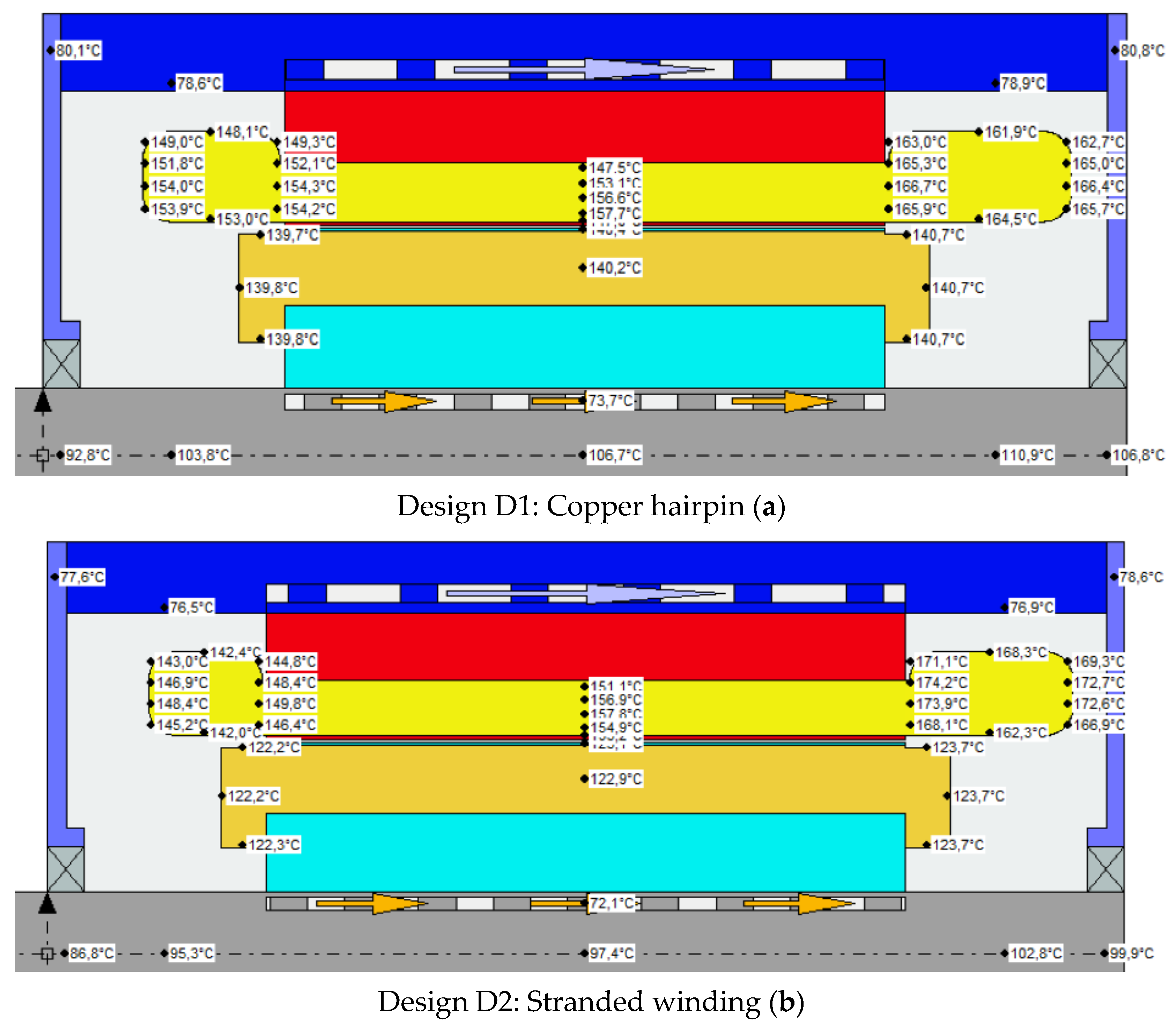
At the same time, the steady-state thermal analysis is carried out to evaluate the maximum temperature reached during continuous operation considering the different stack lengths, the higher thermal conductivity of copper compared to aluminum in the windings, and the consequent better ability to transport heat from the slot to the core.
Figure 4 shows the temperatures for the three compared models starting from an ambient temperature of 50 °C and with the same cooling system.
As confirmed, the temperature hotspots for all the three proposed designs with the rated current reach a steady state just below the maximum temperature allowed for insulation class H. The same temperature limit will also be fixed in the next section to evaluate the peak power performance.
4. Electromagnetic and Thermal Performance at Maximum Power
The maximum performances are evaluated at 6000 rpm considering the maximum phase current imposed for the initial requirements (500
). The results of the three proposed designs at maximum power are shown in
Table 6. Under the same conditions, the transient behaviour from a thermal point of view is also evaluated, starting from an ambient temperature of 50 °Cl the hotspot temperatures for different designs in the thermal transient area at maximum power are represented in
Figure 5.
The three working points are chosen to work at maximum efficiency with the same current and speed. The most efficient project is D1 (89.53%), as expected, followed by D3 (−1.43%) and D2 (−3.33%)
As expected, the initial design (D1) has a thermal transient at maximum power longer (40 s) than the other two solutions. Nevertheless, the higher efficiency of design D3 compared to D2 allows it to maintain the maximum current and higher torque and acceleration for a longer time (19 s respect to 16 s).
5. Efficiency and Losses Maps
The different loss contributions and the efficiency levels of the three designs are evaluated here in the operating range. The map is drawn considering the maximum torque per ampere control strategy (MTPA) and an appropriate field weakening strategy, where the voltage is a limitation up to a maximum speed of 22,000 rpm. The considered maximum current is the rated current (500
) and the DC bus voltage is 800 V with a maximum modulation index of 0.98 [
35].
The following maps show the iron losses and stator winding losses, intending to show how relevant they are to the overall efficiency in an automotive context.
The total losses are strongly affected by the winding losses, as confirmed by the values reported in
Figure 6. While the losses in the iron remain largely constant for the three cases, the joule losses in the windings strongly depend on the choice of winding technology used. In this regard, the losses in the stator windings are further explored and discussed in the maps in
Figure 7, which detail DC and AC losses.
The analyses reported in
Figure 7 show that the DC losses in the stator windings for D1 are lower than the other technologies, due to the low resistivity of copper and the large hairpin slot fill factor. On the other hand, and for the same reasons, the AC losses are larger than the other two projects. Despite this last consideration, the copper hairpins continue to be the choice that provide the lowest losses in the windings of the three designs. Design D2 allows for lower AC losses, even lower than design D3, but despite this the DC losses are significantly greater than the others. Design D3 is halfway between the other two in terms of the stator winding losses, both in terms of AC and DC losses.
In order to evaluate how these losses affect the motor efficiency, the efficiency maps are reported in
Figure 8 for the operating torque and speed characteristics.
The highest losses can be seen for the peak power operations (10–15 krpm), where the combined effect of the peak current, core saturation, and high frequency produces peak losses both in the windings and in the electrical steel material (
Figure 8); nevertheless, the efficiency is maintained above 89% for all three cases in this speed range.
Furthermore, the efficiency maps confirm that design D3 has a trade-off between the performances of designs D1 and D2. In particular, the latter shows a reduction in the gap only at high speeds and high torques thanks to the lower AC losses. In detail, the point at maximum efficiency for D1 is 95.8%, for D2 it is 95.1% (−0.7%), and for D3 is 95.3% (−0.5%).
6. Performance on a Reference Drive Cycle
The aim of this section is to evaluate the performance of the three designs by considering a reference drive cycle and comparing the results for the different winding technologies. Indeed, in the driving cycle, the motor may operate with different torque and speed values, which for much of the time are even lower than the rated ones. The WLTP class 3 driving cycle is selected to evaluate the performances of the three proposed designs, considering the target vehicle mass of 2500
, frontal area of 2.35
, and gear ratio of 11.62 (wheel radius of 0.35
). The torque, speed, and power required by the driving cycle are reported in
Figure 9.
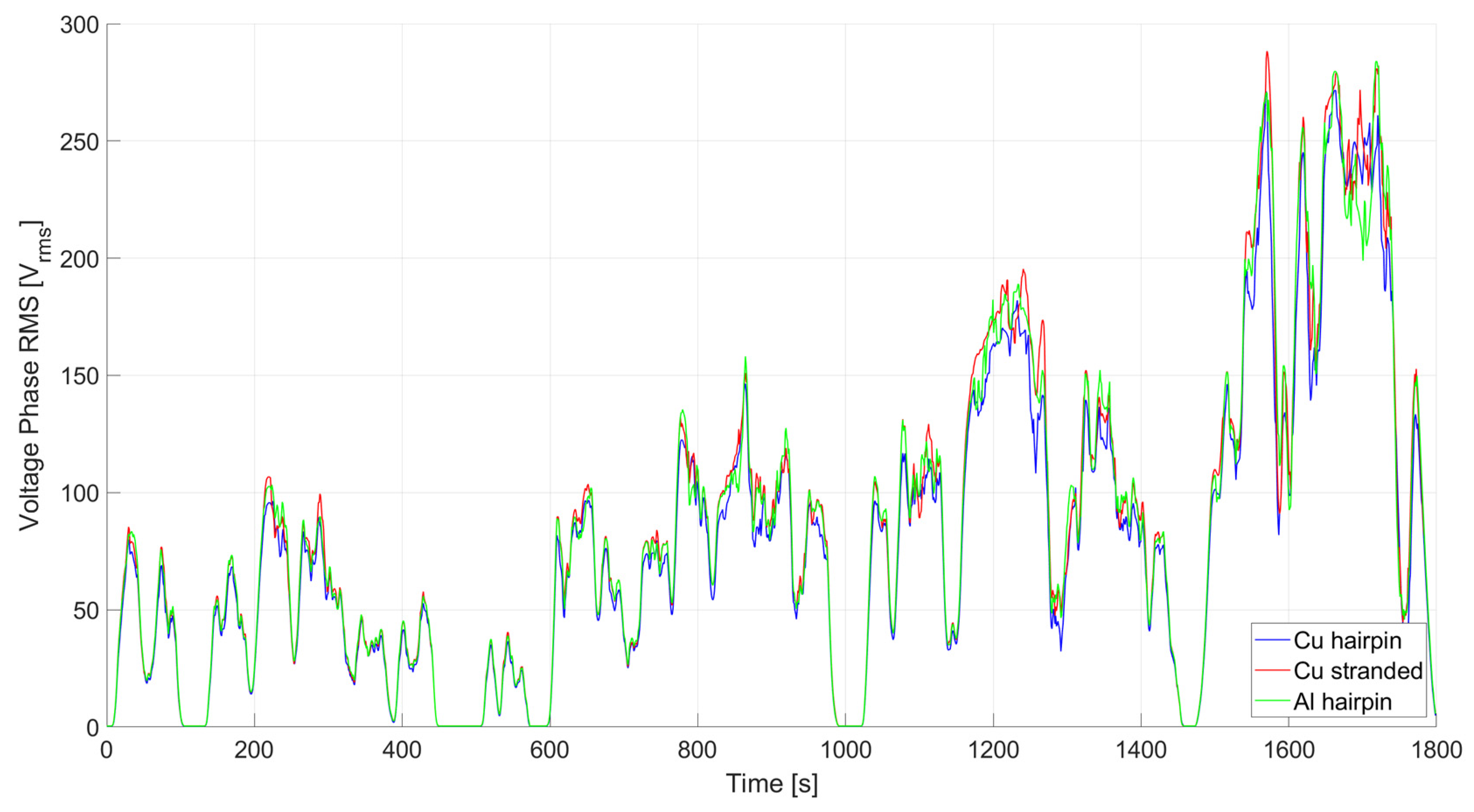
The efficiency, RMS stator phase current, and RMS stator phase voltage are shown in
Figure 10 and
Figure 11 for the different winding technologies.
Concerning the efficiency in
Figure 10, design D1 is always more efficient than the other two designs, despite the current required being higher (
Figure 11). This is clearly closely related to the low resistance of D1 compared to D2 and D3. Moreover, the efficiency of D3 is, for most of the time, higher than D2, even though the required currents are quite similar.
In detail, two zones are highlighted in
Figure 10 to focus on how the driving speed affects the efficiency. In zone A, where the speed required is lower, the differences between the efficiencies of the three projects are more evident, while at high speed this difference decreases. This is justified by looking at the previously reported efficiency maps, which in the higher speed zone are more similar than at low speeds.
Figure 11 shows how the voltage requirements of design D1 are practically always lower than in the other two designs.
The total losses in the stator windings are shown in
Figure 12. In particular, to better investigate the joule losses, they are again detailed for DC and AC components.
The results clearly show that AC losses, even in the worst case for copper hairpins, are considerably lower than DC losses. Hence, although the AC losses in the stranded windings are much lower than those in the hairpin bends, they do not represent the major component in joule losses. The same goes for the comparison between D1 and D3; even if the aluminium hairpins have lower AC losses, this does not make up for the disadvantage caused by the higher DC resistance with respect to the copper hairpins.
Figure 13 shows a comparison of the temperature trends for the motor hotspot over the entire drive cycle.
In all three designs, the temperature is kept below the critical level for the considered insulation class. Concerning the hotspot temperature, it is interesting to note that D3 passes from an initial situation of a slight disadvantage to a slight advantage at the end of the drive cycle; this effect is due to the higher specific heat of aluminium compared to copper.
A comparative table of the results that emerged from the entire drive cycle is presented below (
Table 7).
It can be noticed that the average energy efficiency is influenced in a relevant way by the winding technologies. As expected, design D1 has the best energy efficiency with a value of 93.05%, while the energy efficiency of design D3 is higher than that of design D2 (by about 1%). Indeed, the main differences among the three designs are related to the stator windings losses (D2 at +76% and D3 at +43% with respect to D1). The analyses on the WLTP driving cycle confirm the higher efficiency of the copper hairpin windings, while the aluminum hairpin windings seem to have efficiency benefits compared with stranded wires.
7. Conclusions
This paper presents a detailed analysis of the performance of an induction motor for vehicle applications with different types of stator windings, namely copper hairpin, copper-stranded, and aluminum hairpin windings. After suitable adaptation of the three motors designs, they were evaluated both in terms of the rated operation and in peak power operation, including the thermal motor behavior.
From the analyses carried out here, the following general considerations can be outlined.
The copper hairpin winding technology (design D1) performs better from both an efficiency and thermal point of view. It exhibits peak performance over longer operating times, at more than twice the time length of the other technologies investigated. This is recommended in high-performance or premium vehicles, where peak operation and long-range efficiency is demanded. Nevertheless, the advantages are reduced in high-speed operations due to the AC copper losses, and special attention is needed for motors with more than 4 poles.
The copper-stranded round wire technology (design D2) is affected by the low slot fill factor, which increase the winding losses in the operating region of the machine. The rated and peak performance and the motor efficiency are affected by the higher winding losses, even if AC losses are contained in all the speed ranges of the motor. The adoption of this technology is recommended only for low-performance vehicles (mainly A-segment vehicles) with contained peak performance and limited range issues, unless a higher slot fill factor can be achieved using improved winding technologies.
A study of the suitability of the adoption of aluminum hairpins (design D3) for vehicle applications was the aim of the paper. The analysis carried out highlighted that this technology is a cost-effective approach that can guarantee a trade-off between copper hairpins and stranded wires at lower cost. Therefore, the aluminum hairpin technology is recommended in vehicle segments A to C, which require good torque densities and have heavy cost constraints. In those segments, the aluminum density and contained AC losses can allow for the development of high power density powertrains. Furthermore, the adoption of aluminum windings can reduce potential supply chain risks in mass production related to the high demand for copper windings in the growing renewable energy industry and electric vehicle market.
Moreover, the adoption of aluminum hairpins will improve the effectiveness in mass production scenarios, as the costs of the batteries are envisioned to decrease in the future and new battery technologies will be introduced to increase the vehicle range.
Further developments will address the adoption of aluminum winding technologies in early motor design stages and for different vehicles classes.


