Abstract
This paper introduces a new two-speed planetary gear automatic transmission using an electronically controlled wedge clutch. In order to verify the feasibility of using this transmission in pure electric vehicles, the influencing factors of the two-speed transmission due to the increase in mass and the reduction in transmission efficiency are introduced. The vehicle simulation model was established on the MATLAB/Simulink platform, and the dynamic programming method was used to optimize the transmission ratio and shifting law. The simulation results show that the use of a two-speed automatic transmission can effectively improve the economic performance and dynamic performance of battery electric vehicles.
1. Introduction
At present, the battery electric vehicle transmissions on the market are mainly fixed ratio transmissions. Compared with fuel engines, the electric motor has high efficiency, large torque at low speed, and good speed-adjustable characteristics. Fixed ratio transmissions can basically meet the needs of electric vehicles [1]. Studies have shown that changing the fixed ratio transmission to a two-speed automatic transmission can reduce the performance requirements of the battery and drive motor, and improve the economic performance and dynamic performance of the vehicle [2,3,4,5,6,7,8]. The traditional AT automatic transmission uses a torque converter and a hydraulic control system, which requires the engine to drive the oil pump to continuously rotate during operation, and the transmission efficiency is low [9]. Therefore, it is not suitable for battery electric vehicles that rely solely on low-energy-density battery power sources. In view of the mature technology of planetary gear automatic transmission for traditional fuel vehicles, the literature [10,11] has studied the application of planetary gear two-speed automatic transmission in battery electric vehicles, and concluded that the two-speed planetary gear automatic transmission can meet the power requirements of battery electric vehicles, but it did not give its economic performance and the optimization method of speed ratio selection and shift sequence. To apply two-speed planetary gear automatic transmission to battery electric vehicles, the complexity and inefficiency of its hydraulic shift control system must be reduced and improved. In addition, the impact of increased mass and reduced transmission efficiency compared to single-speed transmission must also be considered.
In this paper, a new type of electronically controlled wedge clutch two-speed planetary gear automatic transmission is used, which cancels the hydraulic torque converter and adopts an electronically controlled wedge clutch for the shifting actuator. Taking a front-drive battery electric vehicle that was equipped with a fixed-speed ratio transmission as the research object, a simulation model was established on the MATLAB/Simulink platform (Version: 9.11.0.1769968(R2021b), University of Science and Technology Beijing, Beijing, China), and the influence of the increase in the mass and the decrease in the efficiency of the planetary gear automatic transmission was introduced. Using a dynamic programming method, in typical urban road conditions such as UDDS in the United States, ECE in Europe, and 1015 in Japan, with the goal of the lowest energy consumption, the transmission ratio and shifting law were obtained. The research results show that the use of the new two-speed planetary gear automatic transmission can effectively improve the economic performance and dynamic performance of battery electric vehicles.
2. Materials and Methods
2.1. Structure and Working Principle
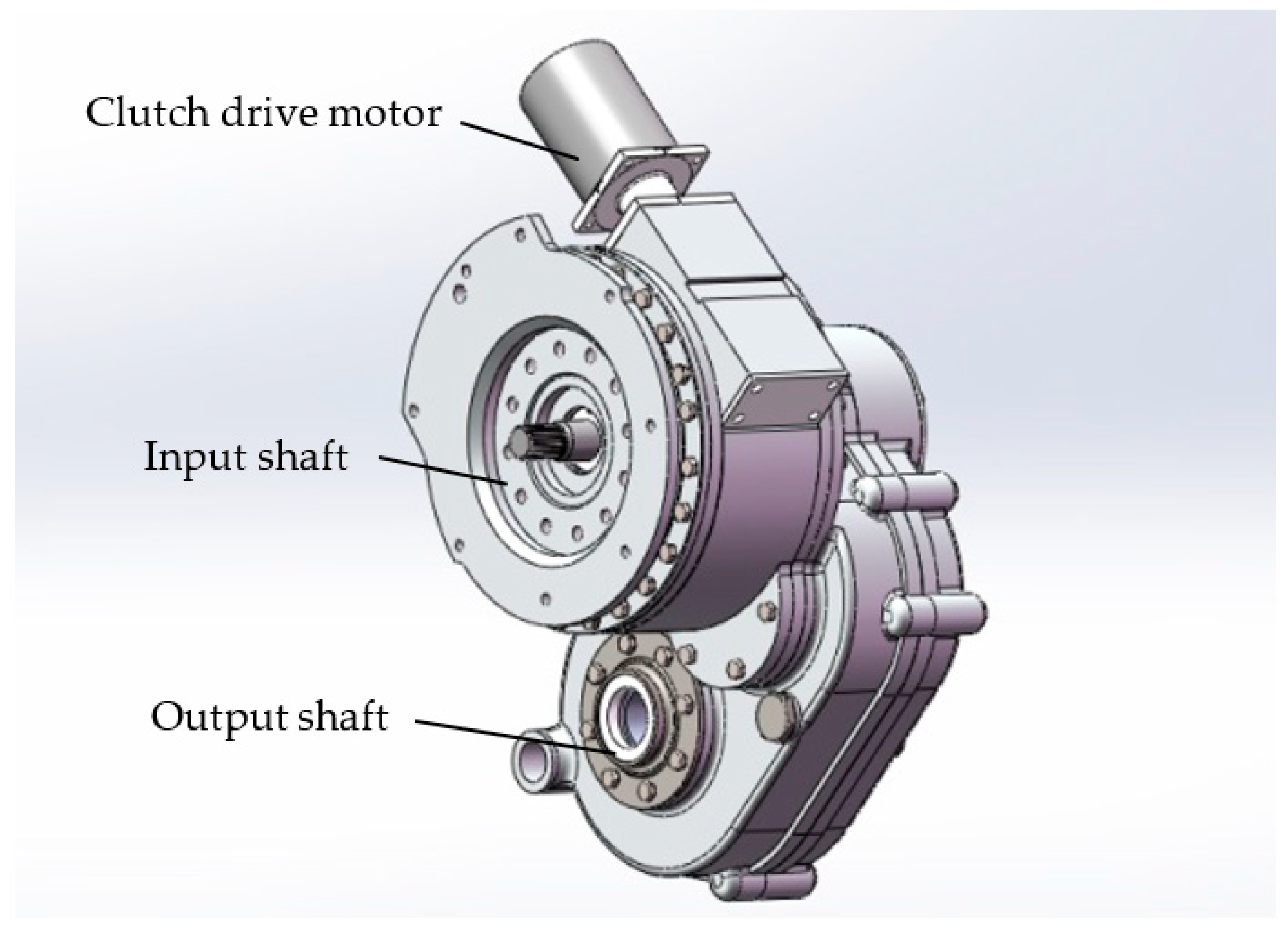
The new two-speed planetary gear automatic transmission (hereinafter referred to as two-speed automatic transmission) is shown in Figure 1. In order to improve the transmission efficiency, the transmission adopts an electronically controlled wedge clutch. The transmission input shaft is connected with the output shaft of the drive motor, and the output shaft is connected with the half shaft. The transmission cancels the torque converter and hydraulic transmission system, and uses the self-energizing characteristics of the wedge clutch to reduce the torque demand of the actuator drive motor. It has the characteristics of small size, low cost, simple structure, high efficiency, fast response, and high control precision.

Figure 1.
Planetary gear automatic transmission with electrically controlled wedge clutch.
The electronically controlled wedge clutch adopts a worm gear and worm actuator, as shown in Figure 2a. The worm is driven by the motor to drive the worm wheel to rotate, thereby driving the wedge block to rotate. The axis of the worm and its driving motor is perpendicular to the axis of the gearbox gear shaft to save the axial position space of the gearbox. The friction plate and steel plate of the wedge clutch (as shown in Figure 2b) are, respectively, connected with the ring gear of the planetary gear mechanism and the transmission housing; the wedge angle is α, and the friction coefficient of the friction plate and the wedge block is μ. During braking, the worm wheel is rotated by the worm driving force . The steel plate is stationary due to the connection with the transmission housing, and the friction plate rotates with the planetary gear. The direction of movement is the same as that of the driving force that is received by the wedge block, resulting in a friction force and a pressing force between the wedge block and the friction plate. If the self-enhancing coefficients of the friction force and positive pressure are defined as and , respectively, according to the force balance of the wedge block, we can get [12]:
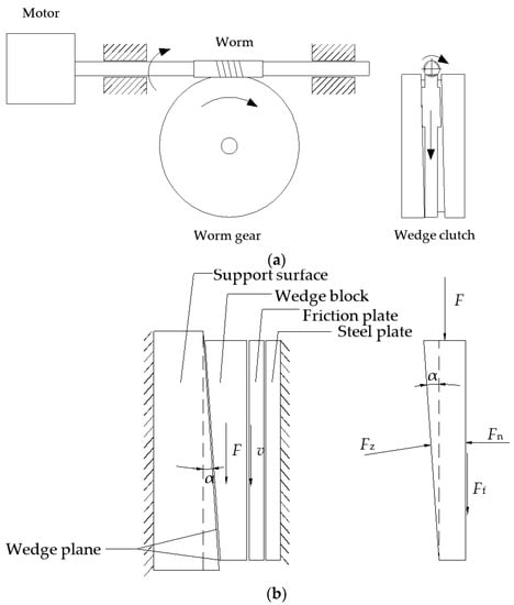
Figure 2.
Electronically controlled wedge clutch system schematic. (a) Wedge clutch actuator schematic diagram. (b) Wedge clutch force schematic diagram.
It can be seen that when the wedge angle α is greater than and close to , the above proportional coefficient increases rapidly, which means that only a small driving force can generate a large positive pressure and friction force. This is the self-energizing property of the wedge mechanism [13,14].
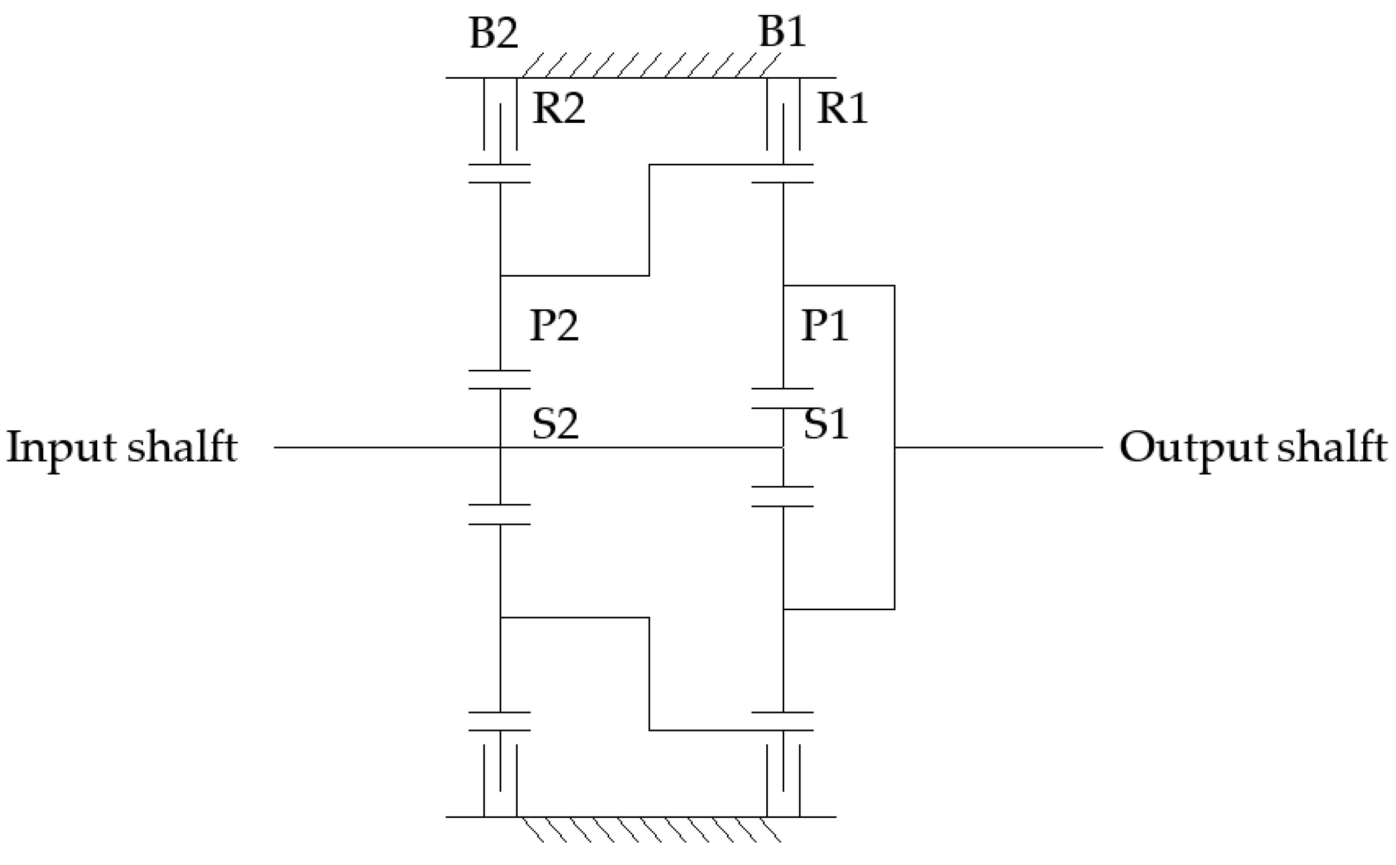
As shown in Figure 3, the automatic transmission is composed of two-stage planetary rows, and the front and rear sun gears S2 and S1 are integrated. The characteristic parameters of the front and rear planetary transmissions are different. The front planet carrier P2 and the rear ring gear R1 are the same member and are output from the rear planet carrier P1. R2 is the ring gear of the front planetary row.
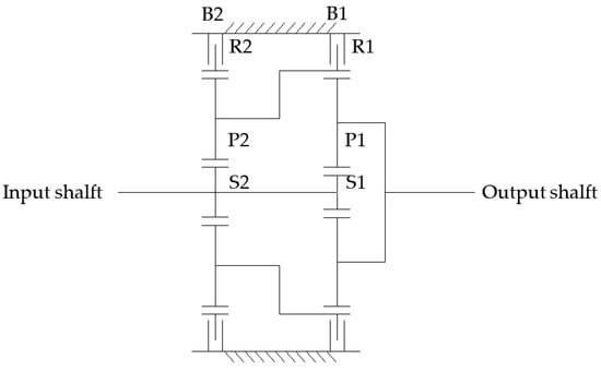
Figure 3.
Planetary gearbox.
Two wedge clutches B2 and B1 are, respectively, connected with the front and rear ring gears. The transmission gears are shown in Table 1. In the table, 1 means that the clutch is closed, and 0 means that the clutch is released. When only the wedge clutch B1 is closed, the transmission is in first gear; when only the wedge clutch B2 is closed, the transmission is in second gear; the reverse gear is realized by the reverse rotation of the electric motor.

Table 1.
Transmission control table.
2.2. Transmission Ratio and Efficiency
The calculation of the transmission ratio and efficiency of the planetary gear mechanism is more complicated, especially for the planetary gear transmission. For different combinations of planetary rows in each gear, the calculation formulas of the transmission ratio and transmission efficiency are different, and the simplified calculation method of the literature [15,16] can be used. The transmission efficiency is calculated using the transmission ratio and the characteristic parameters of the planetary gearbox.
2.2.1. Gear Ratio Calculation
Each individual planetary gear row has an angular velocity equation:
where is the angular velocity of the sun gear, is the angular velocity of the ring gear, is the angular velocity of the planet carrier, is the characteristic parameter of the planetary mechanism and , is the number of teeth of the ring gear, and is the number of teeth of the sun gear.
On the basis of the above component angular velocity equation, the ratio of input and output speeds can be calculated from the connection relationship of the planetary mechanism.
2.2.2. Transmission Efficiency Calculation
The transmission efficiency of the multi-stage planetary gearbox is the ratio of the output power of the transmission to its input power,
where is the transmission efficiency of the planetary transmission mechanism, is the output power, is the input power, is the output torque, is the output speed, is the input torque, is the input speed, is the dynamic transmission ratio, and is the kinematic transmission ratio.
It can be seen from (3) that the kinematic transmission ratio of the planetary transmission mechanism is a function of its characteristic parameter , that is
According to the Kleins (Кляйнс) method, the dynamic transmission ratio of the planetary mechanism is based on the kinematic transmission ratio, and each characteristic parameter value is multiplied by ,
where is the frictional transmission efficiency of the planetary mechanism. The transmission efficiency of the planetary mechanism in this paper is:
where is the friction efficiency between the sun gear and the planetary gear, which is 0.97; is the frictional efficiency between the planetary gear and the ring gear, which is 0.99; and is +1 or −1, obtained from (8)
where when calculated value is greater than 0, sign[] = 1, and when calculated value is less than 0, sign[] = −1. is the partial derivative of the calculation formula of the transmission ratio in this gear to the planetary row characteristic parameter .
3. Vehicle Parameters and Drive Train Model
As shown in Figure 4, using the backward simulation idea and the modular design idea, the vehicle drive chain model of the study is established under the MATLAB/Simulink platform. The model contains road files, vehicle module, drive train module, electric motor modules, and battery module.
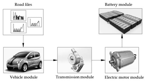
Figure 4.
Drive chain mode.
The model takes the road condition file as input from left to right, and transmits the speed, torque and speed or power requirements. The main parameters of the model are shown in Table 2.
Table 2.
Vehicle parameter.
3.1. Vehicle Module
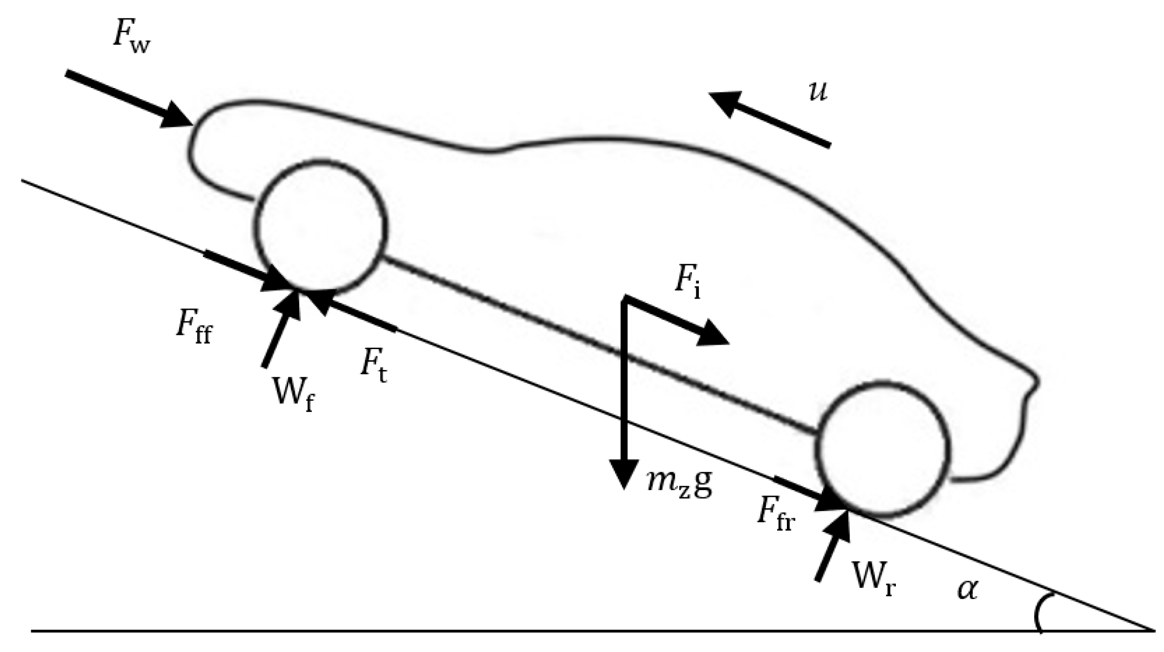
The vehicle is subjected to force along the longitudinal driving direction as shown in Figure 5. During driving, it is subjected to rolling resistance , air resistance , climbing resistance , and acceleration resistance . According to the force balance, the vehicle driving equation is obtained:
where is the driving force, and the other forces are as follows:
where is the mass of the vehicle, is the acceleration of gravity, is the rolling resistance coefficient, is the road slope angle, is the air resistance coefficient, is the windward area, and is the air density. In the simulation step size, let the initial speed be u0 and the final speed be ut, take the average value ur = (ut + u0)/2 as the demand speed, and is the conversion coefficient of the car rotating mass, > 1, du/dt = (ut − u0)/t is the driving acceleration.

Figure 5.
Vehicle force diagram.
Assuming that the wheel radius r remains unchanged during the driving process, the ground adhesion coefficient is sufficient, and the average vehicle speed ur is used as the required vehicle speed. The required wheel torque and rotational speed at a certain time are:
where is the wheel demand input torque, is the braking force, is the wheel drag torque loss, is the wheel acceleration inertia torque, is the wheel demand input speed considering the tire slip rate, and is the tire slip rate.
3.2. Drive Train Module
The speed ratio of the final reducer is . Considering the effects of friction torque loss and acceleration inertia loss , the required input torque and rotational speed of the final reducer are:
Similarly, if the transmission speed ratio is , considering the effects of friction torque loss and acceleration inertia loss , the required input torque and rotational speed of the transmission are:
3.3. Drive Motor Module
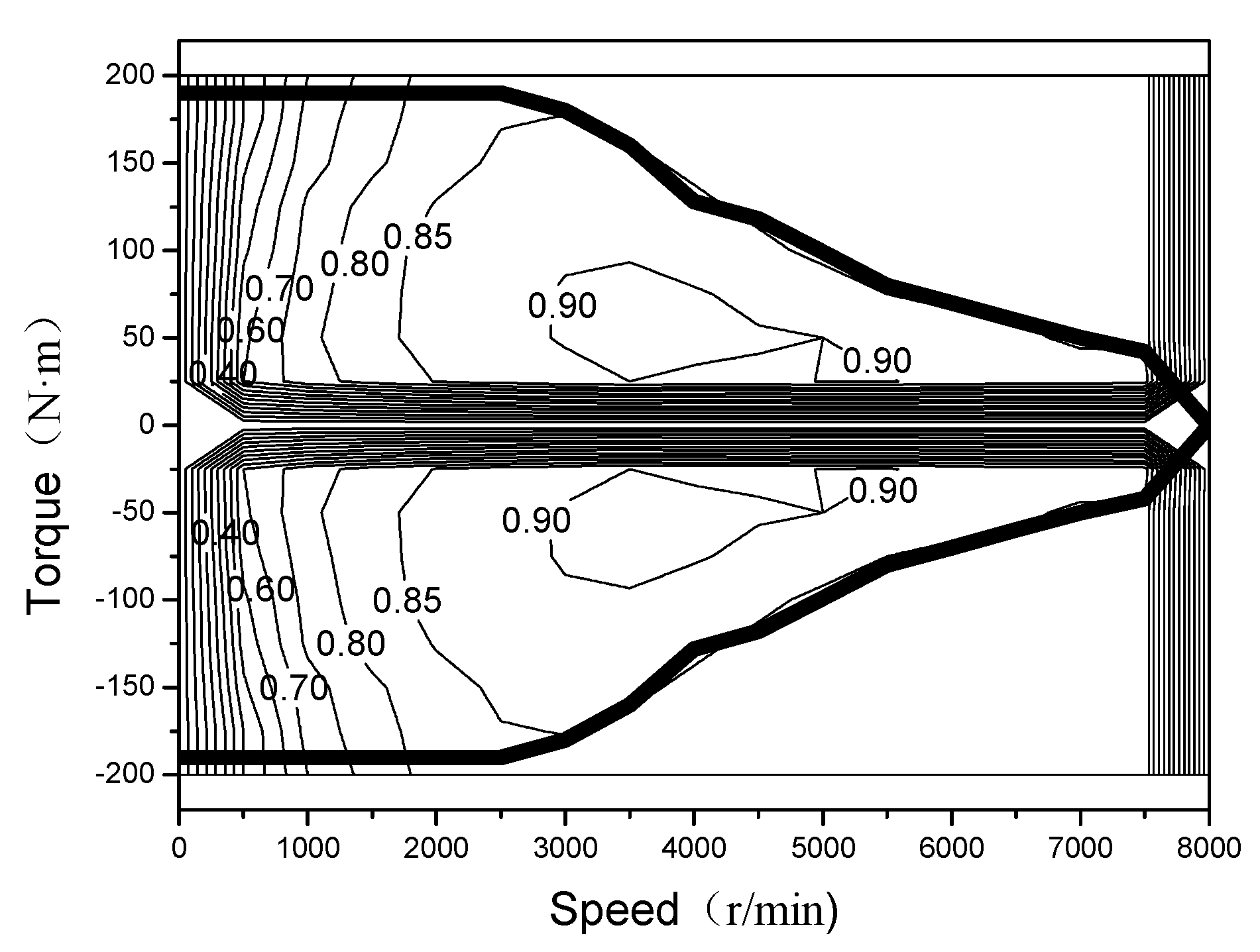
The motor module calculates the motor demand torque and the rotation speed in consideration of the motor acceleration inertia torque loss according to the demand torque and rotation speed that is transmitted by the transmission. By querying the motor torque-speed efficiency MAP to solve the motor demand input power , the motor efficiency is shown in Figure 6:
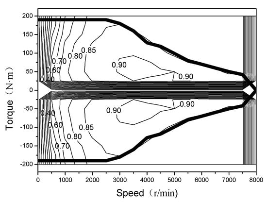
Figure 6.
Motor efficiency map.
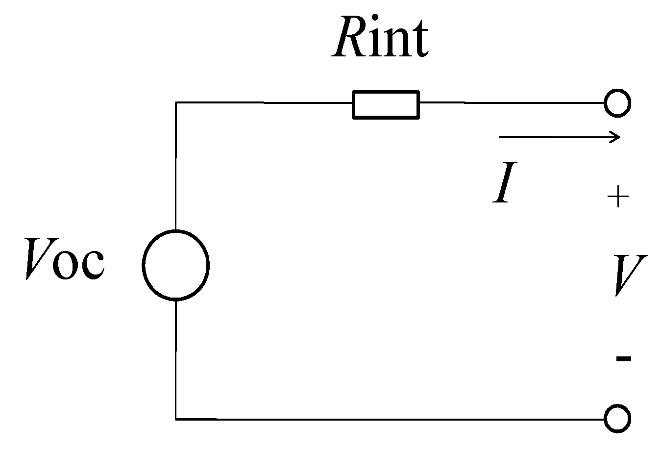
3.4. Battery Module
The battery adopts the Rint model, and the equivalent circuit structure is shown in Figure 7. According to the current SOC value and temperature of the battery, the open-circuit voltage Voc and resistance Rint of the battery (discharge resistance Rd under driving conditions or charging resistance Rc under regenerative braking conditions) are determined by looking up the table. The current I can be obtained according to the power demand Pr, and the battery SOC change ΔSOC can be obtained by the method of continuous iterative step-by-step approximation:

Figure 7.
Rint model of battery.
According to Kirchhoff’s voltage law, the bus voltage V is:
According to the definition of power,
The bus current I can be obtained from (20) and (21):
The battery SOC consumption is:
where is the coulomb efficiency, and is the battery capacity.
4. Transmission Ratio and Shift Schedule Optimization
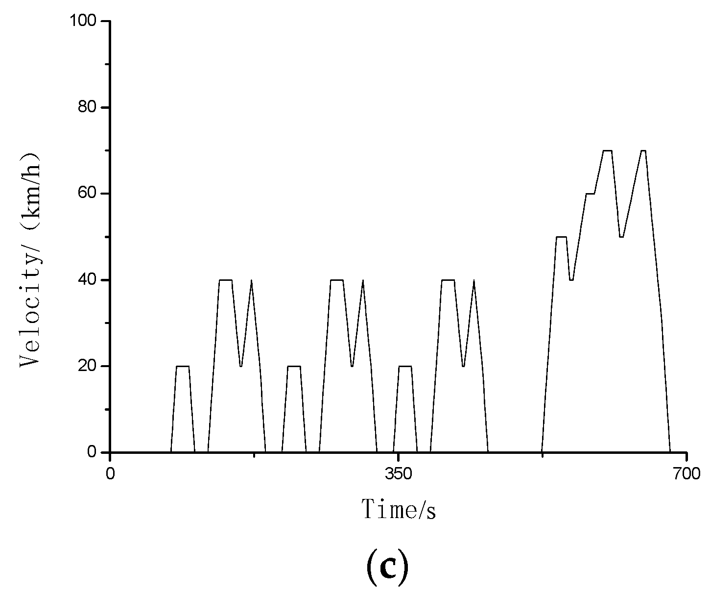
The models that were studied in this paper are mainly used for urban roads, and typical urban roads such as European ECE, American UDDS, and Japanese 1015 are selected for research, as shown in Figure 8.
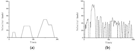

Figure 8.
Typical urban road conditions: (a) ECE, (b) UDDS, (c) 1015.
4.1. Dynamic Programming Algorithm
The dynamic programming algorithm is divided into two types according to the solution sequence: a reverse method such as in the literature [2,5] and a forward method. It is a global optimization algorithm for multi-stage decision-making processes that is especially suitable for global optimization problems under nonlinear, multi-constraint conditions [17]. In the vehicle backward simulation model that was established in Section 3, the total travel time is divided into k stages, and the time interval of each stage is 1 s. Starting from the initial stage, the shift sequence that minimizes the total energy consumption in each stage is calculated, and the transmission gear ratio is the only control variable for each stage.
As shown in Figure 9. The horizontal direction is divided into N stages, and the time interval of each stage is 1 s, and the vertical direction is the discontinuous first gear igb1 and second gear igb2. The horizontal lines ΔSOC(N − 1, 11) and ΔSOC(N − 1, 22) in the figure represent the change in battery SOC when no shifting is performed at the time k = N − 1, and the oblique line ΔSOC(N − 1, 12) in the figure and ΔSOC(N − 1, 21) represent the upshift or downshift battery SOC change amount at time N − 1. The dynamic programming is divided into smaller dynamic programming stages by neutral, and the minimum battery SOC change ΔSOC is used as the objective function. The objective function is:
where i and j are gears, i = 1, 2; j = 1,2.
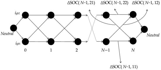
Figure 9.
Dynamic programing.
In order to avoid unnecessary shifting, reduce shifting frequency, and make shifting operation and energy consumption as close to reality as possible, a penalty factor is introduced for correction. The modified objective function formula is as follows:
The dynamic programming algorithm is as follows:
The initial stage k = 0,
k stage, 0 < k ≤ N − 1:
where the transmission gear is the control input, and is the state vector. represents the minimum value of in 0 − k stage. Starting from time k = 0, the time interval is 1 s. By calculating all combinations of and , searching for every possible , the minimum SOC consumption in the k phase is obtained. It can be seen that the dynamic programming problem is the shortest path problem.
In each search step, in addition to satisfying the above equations, the following inequality conditions should also be satisfied:
where is the power that the battery can provide, is the maximum power of the motor, and are the minimum torque (braking) and the maximum torque of the motor respectively, is the maximum speed of the motor, is the initial value of the battery, is the motor minimum allowable voltage, and is the minimum battery voltage.
4.2. Transmission Ratio Optimization
According to automobile theory [18], the transmission ratio i should satisfy the transmission ratio that is determined by the maximum vehicle speed and the ratio that is determined by the maximum ascendable road grade:
where = 120 km/h, the max slope angle is 20%, the average efficiency of the transmission = 0.97. Bring the data in Table 1 to get igb2 ≤ 7.09, igb1 ≥ 3.70. After repeated tests [19], the speed ratio range of the two-speed planetary gear automatic transmission that meets the constraints is selected: igb1 , igb2 .
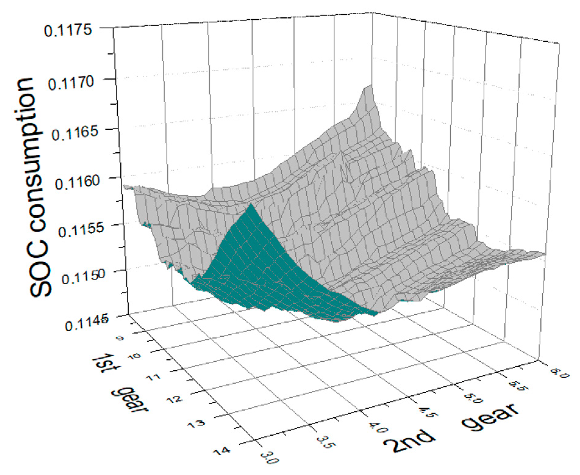
The dynamic programming method that is described in Section 4.1 is used to optimize the above-mentioned different gear ratios, and the minimum SOC consumption can be obtained under the combination of different gear ratios of first gear and second gear. The driving distance of each road condition is introduced as a weight to obtain the weighted SOC consumption under different transmission ratios, as shown in Figure 10. It can be seen that in the selected two-speed transmission gear combination, there is an area with less energy consumption; within this range, there are gear combination points that minimize energy consumption.
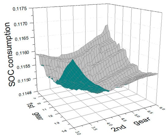
Figure 10.
Different gear combinations and SOC consumption.
For traditional fuel vehicles, in order to reduce the difficulty of shifting, the transmission ratio between adjacent gears is below 1.7–1.8 [20].
For electric vehicles, by optimizing the transmission structure and shifting control method [21], and precisely controlling the motor speed and shifting timing, a wider range of adjacent transmission ratios can be achieved [2,3,22]. The transmission ratio between adjacent gears in literature [2] reaches 2.08, and the literature [3] reaches 3.18. In this paper, the transmission ratio at the lowest point of SOC consumption in Figure 10 is:
4.3. Shifting Schedule
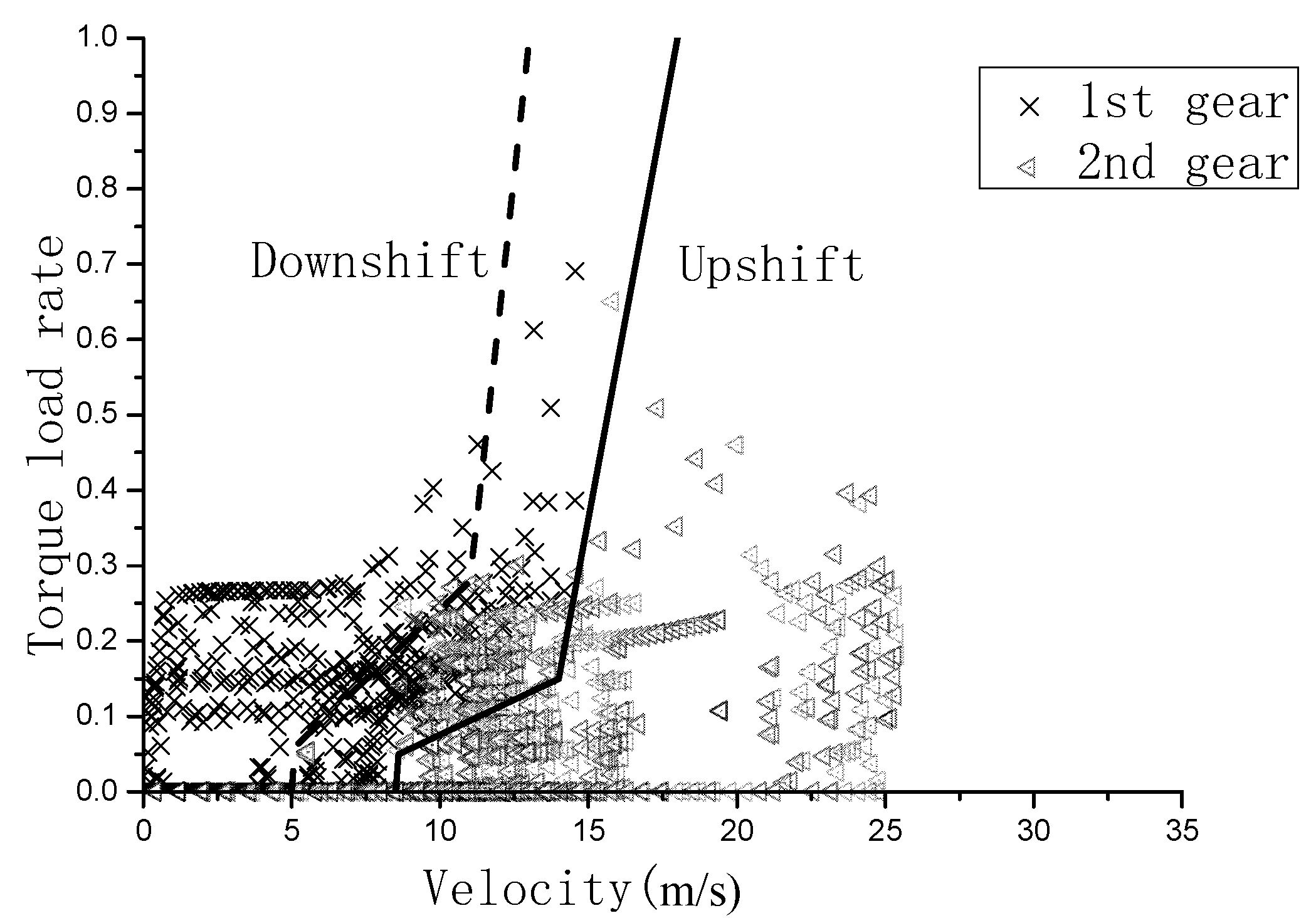
It can be seen from the above research that different gear combinations directly affect energy consumption, and for a two-speed transmission with a given transmission ratio, good shift control is crucial to reducing vehicle energy consumption. Using the transmission ratio that was determined in Section 4.2, under the European ECE, American UDDS, and Japanese 1015 road conditions, taking the motor torque load rate, vehicle speed, and current gear data, Figure 11 can be obtained. It can be seen from the figure that the distribution of different gears is basically divided into two areas, and there is overlap between the areas. According to the figure, the upshift control curve is drawn. In order to prevent cyclic shifting, the downshift curve is processed with a certain delay.

Figure 11.
Gear distribution map and shift curve.
5. Simulation and Result Analysis
Based on the MATLAB/Simulink software platform, using the modular design idea, the hybrid simulation method in which the backward simulation is the main and the forward simulation is supplemented to carry out the simulation analysis of the power and economy of the vehicle [23]. The motor torque load ratio is used to replace the accelerator opening to formulate the speed-motor load ratio two-parameter shift control law, and the vehicle simulation model of the two-speed planetary gear automatic transmission is established.
The two-speed planetary gear automatic transmission will increase the quality of the vehicle and reduce the transmission efficiency, which will affect the efficiency of the vehicle. The mass of the two-speed planetary automatic transmission is set to be 20 kg [2] more than the original fixed speed ratio transmission. The transmission efficiency is calculated by the method of Section 2.2.2, and the transmission efficiency of the fixed speed ratio transmission is 99%. The efficiency of the planetary gear transmission is 97.4% in first gear and 96.7% in second gear.
5.1. Gear Control Sequence and Transmission Efficiency
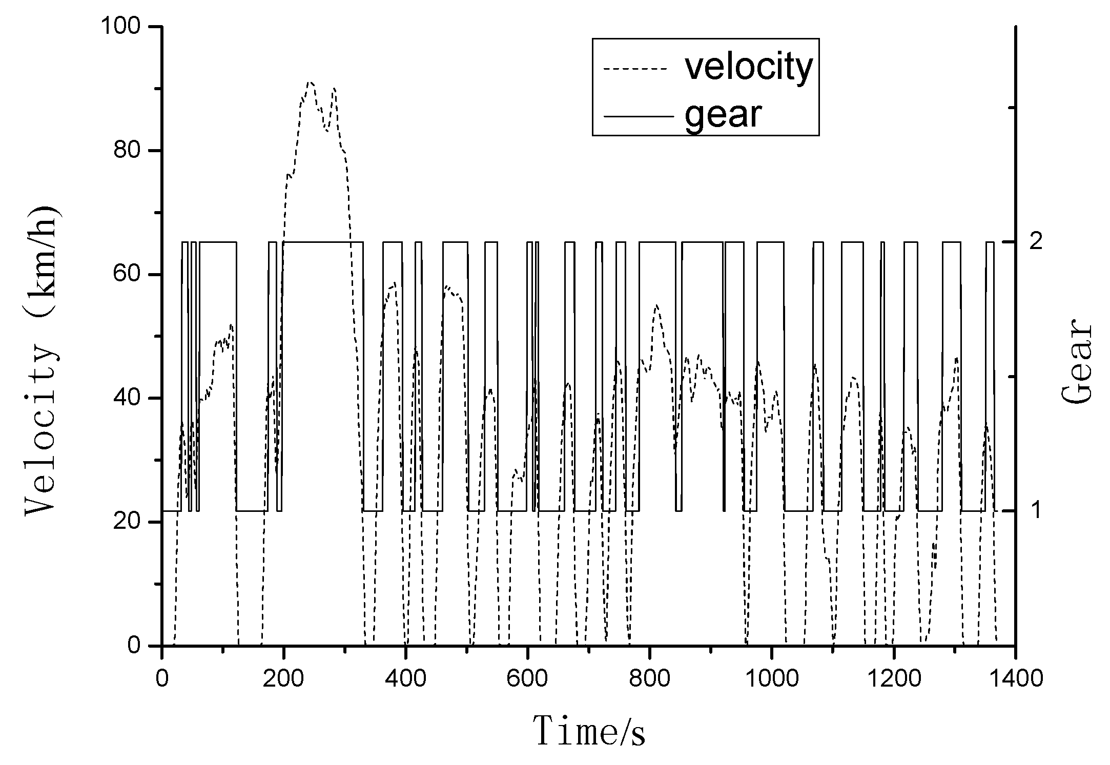
Figure 12 shows the shift sequence of the shift schedule that was established under the UDDS road conditions, which is the most complex of the selected conditions. It can be seen from the figure that the first gear is mainly used for low-speed road sections, and the second gear is mainly used for high-speed road sections. Table 3 shows the efficiency of fixed-ratio transmission and two-speed planetary automatic transmission under different road conditions. It can be clearly seen that the average efficiency of the fixed ratio transmission is higher than that of the two-speed planetary automatic transmission, which is consistent with the previous setting.
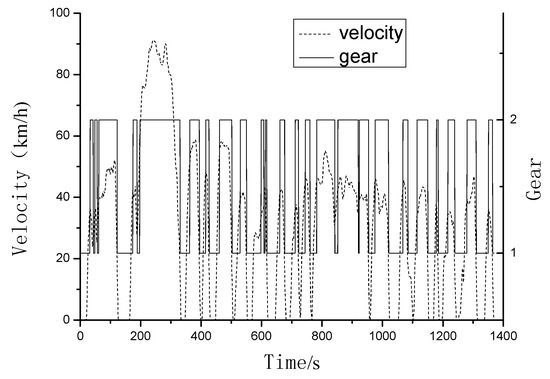
Figure 12.
Gear control sequence.
Table 3.
Transmission efficiency comparison.
5.2. Economic Performance Comparison
Table 4 shows the comparison of the energy consumption data of the fixed ratio transmission and the two-speed automatic transmission. It can be seen that, compared with the fixed speed ratio transmission, although the two-speed planetary gear automatic transmission increases the vehicle mass (20 kg) and reduces the transmission efficiency (about 2%), its use can still reduce the vehicle energy consumption (the highest is 2.25%, the lowest is 0.37%, and the average is 1.22%), which improves the vehicle economy.
Table 4.
Energy consumption comparison.
It can be seen from Table 3 that the transmission efficiency of the two-speed transmission is close to 2% lower than that of the fixed speed ratio transmission. So why does the use of two-speed automatic transmission reduce the energy consumption of the car? This needs to be analyzed from the working point of the motor and its efficiency.
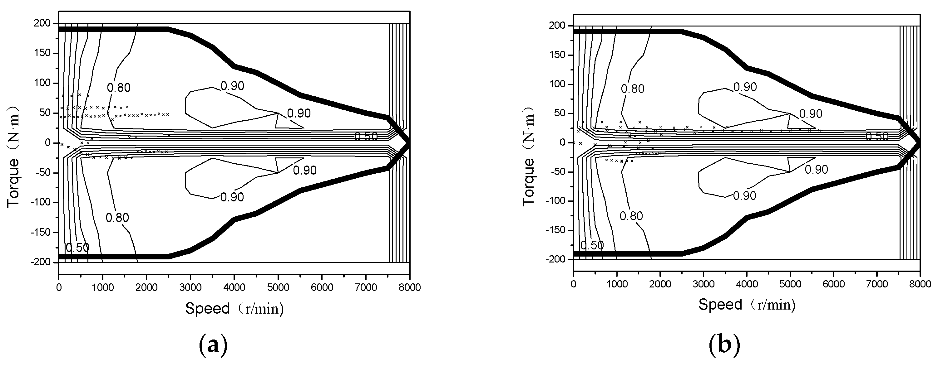
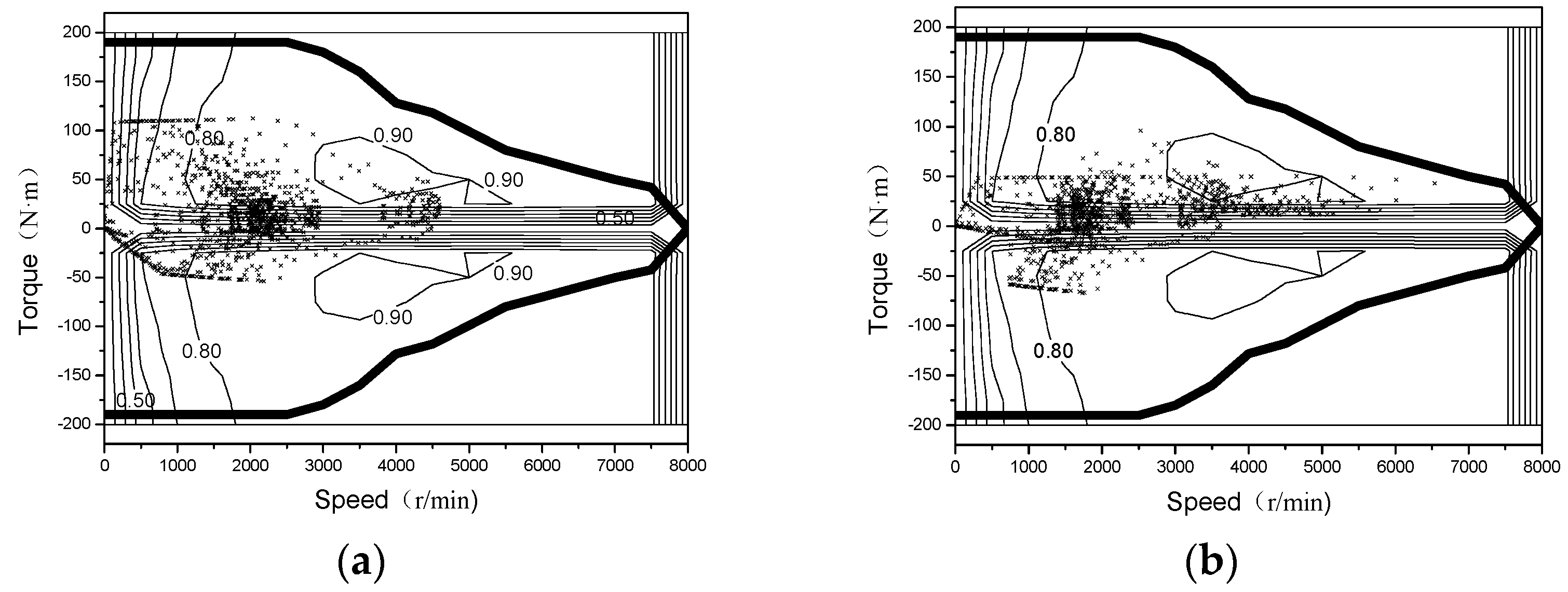
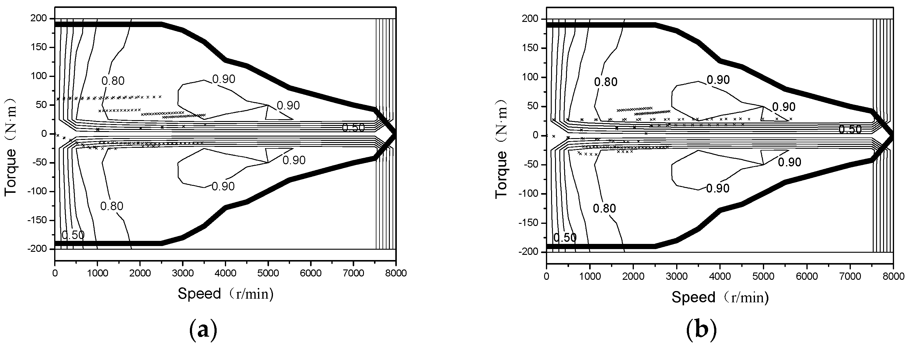
Figure 13, Figure 14 and Figure 15 are the comparison of the motor operating points () of the fixed-speed ratio transmission and the two-speed planetary automatic transmission under different road conditions. Obviously, with the two-speed automatic transmission, the working point of the motor is closer to the high-efficiency area of the motor. Table 5 shows the driving efficiency values of the motor under different road conditions. The efficiency of the motor increases by 2.05–3.57% under different driving conditions.
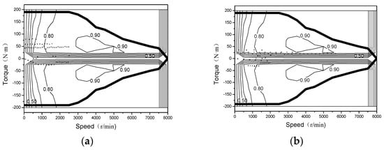
Figure 13.
Motor operating point comparison (ECE). (a) Fixed ratio transmission. (b) Two-speed planetary transmission.
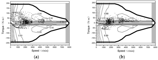
Figure 14.
Motor operating point comparison (UDDS). (a) Fixed ratio transmission. (b) Two-speed planetary transmission.
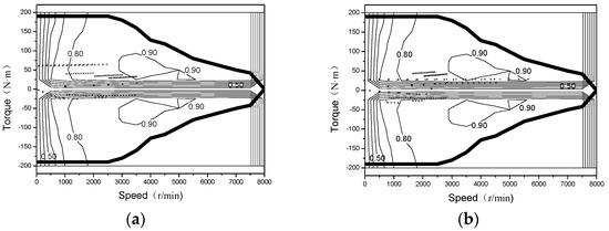
Figure 15.
Motor operating point comparison (1015). (a) Fixed ratio transmission. (b) Two-speed planetary transmission.
Table 5.
Motor efficiency comparison.
The use of a two-speed automatic transmission increases the energy consumption of the entire vehicle due to the increase in mass and the decrease in the transmission efficiency compared with the fixed speed ratio transmission. However, the two-speed transmission can optimize the working point of the motor through gear switching, reduce motor torque, and current, thereby reducing motor losses, and move the working point of the motor to the high-efficiency area, which improves the efficiency of the motor. These are enough to make up for the reduction in the transmission efficiency that is caused by the use of a two-speed planetary gear automatic transmission, thereby improving energy efficiency.
5.3. Power Performance Comparison
Table 6 lists the acceleration time, maximum grade, and maximum speed data for the different transmissions. It can be seen that compared with the fixed ratio transmission, the two-speed automatic transmission reduces the vehicle acceleration time, and the 0–50 km/h acceleration time is reduced from 5.4 to 3.8 s, 0–100 km/h acceleration time reduced from 15.9 to 15.3 s. The maximum gradeability at 30 km/h is increased from 28.7 to 42.6%. Of course, the above conclusion is in the case of a good road surface and sufficient adhesion. The given values may become unrealistic due to wheel adhesion limitations. The two-speed automatic transmission introduces a large transmission ratio in the first gear, which can increase the output torque of the transmission, especially when running at low speeds, thereby improving the vehicle’s climbing ability and acceleration ability. The maximum speed is mainly limited by the maximum power of the motor, and there is no significant change.
Table 6.
Dynamic performance comparison.
6. Conclusions
Compared with the fixed ratio transmission, the two-speed planetary gear automatic transmission increases the mass of the vehicle and reduces the efficiency of the transmission. However, it can optimize the working point of the drive motor to move closer to the high-efficiency area through gear switching, and improve the working efficiency of the motor, thereby making up for its inefficiency and reducing the energy consumption of the vehicle. Under the three selected road conditions, the working efficiency of the motor is increased by 2.05–3.57%, and the energy consumption of the power battery is reduced by 0.37–2.25%. The simulation results of the vehicle dynamic performance shows that the use of the new two-speed automatic transmission can significantly improve the vehicle’s acceleration performance and climbing ability. Under good road adhesion conditions, the acceleration performance 0–50 km/h increased by 30%, 0–100 km/h increased by 4%, and 30 km/h climbing ability increased by 48%.
At the same time, it can be seen that under different road conditions, the two-speed automatic transmission has great differences in the reduction of vehicle energy consumption. If the method of this paper is used to optimize the design of a certain road condition, the two-speed planetary gear automatic transmission that is used in this paper can improve the economy of the vehicle by more than 3%.
It must be noted that the improvement of vehicle economic performance and dynamic performance is a multi-objective optimization problem. Other structural components and control strategies of the vehicle have not been changed in this paper. To further improve vehicle performance and give full play to the role of the two-speed planetary gear automatic transmission in improving vehicle performance, it is necessary to optimize the selection of components such as drive motors and improve control methods such as regenerative braking control strategies.
Author Contributions
Conceptualization, W.Z. (Wenming Zhang); Methodology, W.Z. (Wenming Zhang), and J.Y.; Software, J.Y. and W.Z. (Wei Zhang); Validation, W.Z. (Wenming Zhang), J.Y., and W.Z. (Wei Zhang); Formal analysis, W.Z. (Wei Zhang); Investigation, W.Z. (Wei Zhang); Resources, J.Y. and W.Z. (Wei Zhang); Data curation, W.Z. (Wei Zhang); Writing—original draft preparation, W.Z. (Wei Zhang); Writing—review and editing, W.Z. (Wei Zhang) and J.Y.; Visualization, W.Z. (Wei Zhang); Supervision, W.Z. (Wenming Zhang); Project administration, W.Z. (Wei Zhang). All authors have read and agreed to the published version of the manuscript.
Funding
This research was funded by National Key R&D Program of China (No. 2018YFC0604402) and the key project of scientific research in colleges and universities of Anhui Provincial Department of Education (No. KJ2021A0880).
Institutional Review Board Statement
Not applicable.
Informed Consent Statement
Not applicable.
Data Availability Statement
The data presented in this study are available on request from the corresponding author.
Conflicts of Interest
The authors declare no conflict of interest.
References
- Huang, W.; Wang, Y.; Feng, K.; Zhang, J. Development of two-speed automatic transmission for electric vehicle. Automob. Technol. 2011, 2011, 17–21. [Google Scholar]
- Gao, B.; Liang, Q.; Xiang, Y.; Guo, L.; Chen, H. Gear ratio optimization and shift control of 2-speed I-AMT in electric vehicle. Mech. Syst. Signal Process. 2015, 50–51, 615–631. [Google Scholar] [CrossRef]
- Qin, D.; Zhou, B.; Hu, M.; Hu, J.; Wang, X. Parameters design of powertrain system of electric vehicle with two-speed gearbox. J. Chongqing Univ. 2011, 34, 1–6. [Google Scholar]
- Wang, X.; Cai, Y.; Zhou, Y.; Gao, S. A study on the effects of matching of automatic transmission on the energy consumption of electric vehicle. Automot. Eng. 2014, 36, 871–878. [Google Scholar]
- Wu, G.; Zhang, X.; Dong, Z. Impacts of Two-Speed Gearbox on Electric Vehicle’s Fuel Economy and Performance; Sae Technical Papers; SAE International: Warrendale, PA, USA, 2013; Volume 2, pp. 681–683. [Google Scholar]
- Zhan, C.; Wang, Q. Design and Optimization of Transmission Parameters of Electric Vehicle Based on Improved Genetic Algorithm. J. Chongqing Univ. 2020, 34, 1–5. [Google Scholar]
- Zhao, K.; Yao, W.; Liu, Y.; Ye, J. A Study of Power Shift Mechanical Transmission for Pure Electric Vehicle. China Mech. Eng. 2015, 26, 1697–1703. [Google Scholar]
- Zheng, J.; Chen, J. Optimization Design of Pure Electric Vehicle Power System Speed Ratio. J. Mech. Transm. 2019, 43, 79–82+93. [Google Scholar] [CrossRef]
- He, Z.; Bai, H. Automatic mechanical transmission technique development actuality and expectation. Trans. Chin. Soc. Agric. Mach. 2007, 38, 181–186. [Google Scholar]
- Wang, D.; Zhang, S.; Xu, S.; Li, X. Modeling and simulation of planetary gear type continuously variable transmission of electric vehicle. J. Chongqing Univ. Technol. Nat. Sci. 2010, 7–11. [Google Scholar]
- Wang, T.; Zhang, J.; Zhang, H.; Xiong, J. Simulation of electric vehicle’s performance with planetary gear two-speed transmission. China Meas. Test 2014, 40, 125–128. [Google Scholar]
- Balogh, L.; Stréli, T.; Németh, H.; Palkovics, L. Modelling and simulating of self-energizing brake system. Veh. Syst. Dyn. 2006, 44, 368–377. [Google Scholar] [CrossRef]
- Hartmann, H.; Schautt, M.; Pascucci, A.; Gombert, B. eBrake®—The Mechatronic Wedge Brake. Braking Syst. 2002, 11, 2146–2151. [Google Scholar]
- Yao, J.; Chen, L.; Yin, C. Modeling and Stability Analysis of Wedge Clutch System. Math. Probl. Eng. 2014, 2014, 712472. [Google Scholar] [CrossRef] [Green Version]
- Jiao, W.; Ma, F.; Yang, Y.; Zhao, X. Calculation of transmission ratio and effeciency of planetary gear box. J. Mech. Transm. 2012, 114–116. [Google Scholar]
- Shin, J.W.; Kim, J.O.; Choi, J.Y.; Oh, S.H. Design of 2-speed transmission for electric commercial vehicle. Int. J. Automot. Technol. 2014, 15, 145–150. [Google Scholar] [CrossRef]
- Cheng, Y.; Li, X.; Luo, J. Optimization of shifting schedule for vehicle with automated mechanical transmission. Comput. Simul. 2016, 3, 227–231. [Google Scholar]
- Zhang, W. Theory of Automobile, 3rd ed.; China Machine Press: Beijing, China, 2021. [Google Scholar]
- Wang, S.; Liu, J.; Ma, Z.; Wang, L. Design of Electric Vehicle Two-speed Transmission Ratio based on NEDC. J. Mech. Transm. 2020, 44, 79–83. [Google Scholar] [CrossRef]
- Yu, Z. Automobile Theory, 3rd ed.; China Machine Press: Beijing, China, 2020. [Google Scholar]
- Ye, J.; Zhao, K.; Huang, X.; Liu, Y.; Yao, W. Motor Coordinate Shift Control for a Two-speed Uninterrupted Shift Transmission of Pure Electric Vehicle. Automot. Eng. 2016, 38, 989–995+973. [Google Scholar] [CrossRef]
- Glielmo, L.; Iannelli, L.; Vacca, V.; Vasca, F. Gearshift control for automated manual transmissions. IEEE/ASME Trans. Mechatron. 2006, 11, 17–26. [Google Scholar] [CrossRef]
- Zheng, X.; Gong, W. ADVISOR 2002 EV Simulation and Redevelopment Applications; China Machine Press: Beijing, China, 2014. [Google Scholar]


Publisher’s Note: MDPI stays neutral with regard to jurisdictional claims in published maps and institutional affiliations. |
© 2022 by the authors. Licensee MDPI, Basel, Switzerland. This article is an open access article distributed under the terms and conditions of the Creative Commons Attribution (CC BY) license (https://creativecommons.org/licenses/by/4.0/).