Abstract
With the continuous improvement of automatization of underground oil and gas resources exploitation, more and more instructions are required for the control technology while drilling in complex processes. The conventional downlink communication technology has shortcomings, such as data transmission lag and high bit error rate, which cannot meet the actual needs. Therefore, developing a new high-speed and low bit error rate (BER) downlink communication technology is very important. In this study, a new type of downlink communication system based on the electric current field is designed. Firstly, based on the theory of electromagnetic field and electromagnetic wave, the current distribution model of the drill string is established. Then, the magnetic field distribution model of the drill string is deduced according to the research on the static electromagnetic field and boundary problems. Finally, the ground simulation experiment platform of the downlink communication system is built and tested. The experimental results show that the BER is only 1.02% when the data transmission rate is 1 kbps. To further reduce the BER of the system, the influence factors of information transmission such as different transmitting voltage, inter-electrode distances, and working temperature are tested and analyzed, respectively, which provides ideas for optimizing the technology of downlink information communication while drilling.
1. Introduction
With the continuous development of the economy, oil and gas resources have become one of the most important energy sources in the world [1]. However, there are many difficulties in the exploitation of oil and gas resources, including the low accuracy of an automatic drilling system in downlink communication and the low feedback rate of bottom hole parameter information. One of the most important links in the process of oil and gas resource exploitation is to transmit the control command of the downhole automatic drilling system with low BER. If the control fails or any wrong control occurs, it will not only cause large economic losses, but also cause serious safety accidents. Due to the complex downhole environment, large noise interference, and low BER downlink communication of control commands requires high information transmission technology, which makes the control of the downhole automatic drilling system very difficult [2]. Therefore, it is of great significance to develop a high-speed and low BER downlink communication technology.
The existing downhole information transmission methods mainly include cable, optical fiber, smart drill string, electromagnetic wave, acoustic wave, drilling fluid pressure wave, etc. [3]. Wired information transmission technologies such as cables, optical fibers, smart drill are generally vulnerable to extrusion and wear, resulting in high cost and great installation difficulty [4,5,6]. Downhole information transmission by wireless communication technology can effectively avoid problems such as wear and compression. The transmission speed of electromagnetic waves is fast and can be applied to air drilling, foam drilling, laser drilling, and other fields. However, the transmission distance of electromagnetic waves is limited, which is unsuitable for ultra-deep well construction [7]. Sound wave transmission uses the propagation of the sound wave in the medium for communication. The transmission mode is simple, and the cost is low. However, in the acoustic transmission channel, the noise is strong, the interference is large, and the attenuation is serious, which lowers the transmission accuracy [8,9]. The drilling fluid pressure pulse transmission method uses the drilling fluid as a channel for pressure wave information transmission, which is the most widely used technology at present [10,11]. An early measure while drilling (MWD) mud telemetry system generates a pressure pulse in the mud channel using a plunger valve and transmits downhole data with the baseband transmission pattern. The data rate is low, at approximately 3 bits per second. Now, the baseband transmission pattern has been replaced by a frequency band transmission pattern with a continuous pressure wave mud telemetry system for a relatively higher data rate up to 20 bits per second and better tolerance of normal noise sources [12]. However, the efficiency of the MWD mud telemetry system still needs to be further improved.
With the rapid development of information transmission technology, various new technologies have been developed. Liu Q.Y. proposed a method of information transmission based on radio frequency identification technology. In this way, the Radio Frequency Identification (RFID) tag carrying the command to be transmitted is put into the drill pipe at the wellhead and pumped down the tag. Then, the command is identified by the reader to realize the purpose of downlink communication. However, the RFID tag identification code used in this method is single-use, which is not easy to be modified or reused [13]. Ma D. first applied vector orthogonal frequency division multiplexing (V-OFDM) modulation technology to downlink communication technology, and studied different synchronization timing errors and detection schemes. Then, they gave a performance analysis of different schemes [14]. The application of electric current field information transmission technology has attracted much attention due to its low production cost and simple operation. However, the weak current-carrying information in electric current field information transmission has restricted its development to a certain extent. At present, the main application occasions of electric current field information transmission are generally in underwater, mine, subway emergency communication, and other fields [15]. Schiltz C. W pointed out that the technology of communication by conducting electric current field was feasible, and introduced a wireless transceiver device based on electric current field communication [16]. The underwater electric conduction channel characteristics, such as the path loss and time dispersion, are obtained from a channel measurement campaign in open sea waters by Kim. C. W. Implications of the channel characteristics to digital communications design are discussed [17]. Xiang X. used the electric current field to realize the underground communication through the stratum, and analyzed the relationship between the field strength of the electric current field with the transmission distance and the size of the emission dipole electrode under the constant flow field electromagnetic wave propagation model [18]. Yang T.H. constructed the channel model of the rock and soil layer, and proposed a specific implementation scheme of throughground communication system combining software and hardware, which provided a theoretical basis for the follow-up research [19].
In recent years, with the rapid development of electromagnetic measurement technology [20], anisotropic magnetoresistance detection technology has emerged [21,22]. This technology is widely used in the field of non-contact weak current detection because of its high sensitivity and low cost. In view of the great advantages of anisotropic magnetoresistance technology in weak current detection, this study combines the electric current field information transmission technology with the anisotropic magnetoresistance weak current detection technology [23,24], which greatly improves the practical operability of electric current field information transmission, and effectively makes up for the shortage of electric current field wireless communication.
In this paper, the mathematical model of the current field and magnetic field distribution around the drill string is established, and the influencing factors of the current field wireless communication mode are analyzed [25] to study the information downlink communication technology with high speed and low bit error rate in the process of oil and gas resource development. At the same time, the information downlink communication system based on anisotropic magnetoresistance detection is theoretically analyzed and modeled, and the relevant experimental platform is built. Through experimental tests and analysis, the influence relationship of key parameters such as transmitting voltage, electrode spacing, and working temperature on information transmission is obtained, which provides a theoretical and technical basis for further optimizing downlink information and communication technology while drilling.
2. Downlink Communication and Modeling of Information While Drilling Based on Anisotropic Magnetoresistance Detection
In order to study the current distribution and magnetic field distribution around the drill string, the structure of the downlink communication system based on anisotropic magnetoresistance detection was firstly modeled. In the electric current field communication mode of injecting current on the electrode, two electrodes were connected at both ends of the transmitter as antennas, and the electrodes are in good contact with the rock and soil layer. The carrier signal (alternating voltage) carrying information was sent to the two electrodes at the transmitting end [26,27]. The drill string is a good conductor that can be used to replace one of the electrodes to allow alternating current to flow through the drill string. The anisotropic magnetoresistance technology fixed on the drill string measures the current change on the drill string and extracts the information carried by it, so as to realize the communication. By using this communication mode, the antenna structure can be greatly simplified, and the purpose of wireless communication has been realized. At the same time, the electrode position can be changed at will, which has strong flexibility. The simplified structure model of the down transmission system of information while drilling based on anisotropic magnetoresistance detection is shown in Figure 1, and the structure of the bit, drill string, and drill collar are simplified as the drill string of Figure 1. In the picture, the drill string, earth, and electrode form a loop. The transmitter sends out a signal, which is transmitted to the bottom of the well through the drill string and received by the receiver.
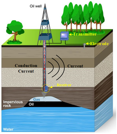
Figure 1.
Structure model of downlink communication system based on anisotropic magnetoresistance detection.
The following assumptions are made on the premise that the electrode at the end of the transmitter is replaced by the drill string:
- Drill string belongs to the metal conductor, its conduction current is much greater than the displacement current, the displacement current can be ignored
- The conductivity of electrode and drill string is much higher than that of rock soil and drilling fluid. The surface is approximately equal potential, which conforms to the boundary conditions of the electrostatic field
- The medium in the rock, and soil layer remains unchanged
- The magnetoresistance sensor is close to the drill string
- Because the drill string is usually several thousand meters long, the drill string is approximately regarded as a thin line
- The carrier signal with the communication frequency not higher than 30 kHz can be regarded as the direct current (DC) power supply.
2.1. Mathematical Model of Downhole Drill String Current Distribution
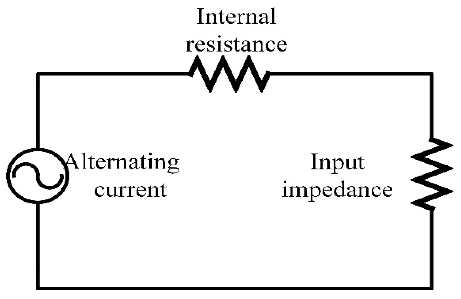
In order to study a new type of downlink communication technology based on anisotropic magnetoresistance technology, the current distribution of downhole drill string is modeled. According to the study, when verylowfrequency (VLF) alternating current (AC) is injected into the electrode, the distribution of electric current field in rock and soil layer can be approximately regarded as the electric field distribution of electrostatic field dipole [28]. According to the electric field line and potential distribution of electric dipole electrostatic field, the electric current field distribution of a pair of electrodes in rock and soil layer can be similar. The rock and soil layer belongs to semiconductor medium. Under the known dielectric constant of the rock and soil layer, when an AC voltage U varying with time is applied between the electrodes, an alternating current will flow along the electric field line between the two electrodes. The relationship between the current and voltage of the whole system can be equivalent to that of the circuit system composed of multiple capacitors and resistors in series and parallel relationships.
Before establishing the rock and soil layer’s current model, the volume of the rock and soil layer is infinite, with the conductivity and the dielectric constant . Then, a pair of electrodes with applied voltage U and distance L can be equivalent to the model shown in Figure 2.
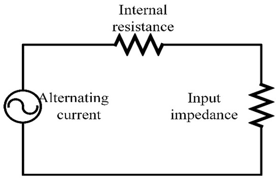
Figure 2.
Equivalent circuit diagram.
The resistivity of the drill string is far less than that of rock and soil layer. To facilitate subsequent analysis, assumingthat the drill string is a straight line with uniform and charged quantity q. Then, the charge distribution law of the drill string can be expressed as , H is the length of the downhole drill string.
The potential function of the electric field generated by the point charge q at point r can be expressed as Equation (1):
According to the model shown in Figure 3, the potential generated by an arbitrary point charge dy at point −q with the distance r can be expressed as Equation (2):
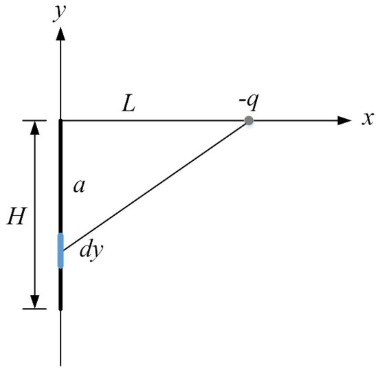
Figure 3.
Model connected to drill string.
In practice, the drill string is usually surrounded by drilling fluid, and its conductivity is much lower than that of common metals. According to the boundary conditions and voltage relations, it can be concluded that the tangential components of the two media in the electrode are continuous, as shown in Equation (3):
Assuming that the electric field in the two media is uniform, the voltage can be obtained by Equation (4):
where d1 is the width of drilling fluid, is the conductivity of drilling fluid, d2 is the width of rock and soil layer, is the conductivity of rock and soil layer. Since , the influence of drilling fluid on field strength can be ignored. According to the proportional relationship between the constant electric field and the static electric field, the voltage expression of any current element flowing through the rock and soil layer is given in Equation (5):
where, I is the transmitting current of the transmitter.
The impedance of the conductor and electrode is much less than that of rock and soil, so the impedance of the conductor and electrode can be ignored, and the input impedance Z is equivalent to the impedance of the rock and soil layer. The transmitting current can be obtained by Equation (6):
The current at any point a on the drill string is equal to the sum of all current elements from a to H, that is . Its differential form is shown in Equation (7):
Equation (8) can be obtained by substituting Equation (6) into Equation (7):
By solving Equation (8), Equation (9) is obtained:
is the power supply voltage of the transmitter, σ is the conductivity of the rock and soil layer, Z is the input impedance value, H is the length of the downhole drill string, L is the distance between two electrodes, and a is the distance from any point of the drill string to the ground.
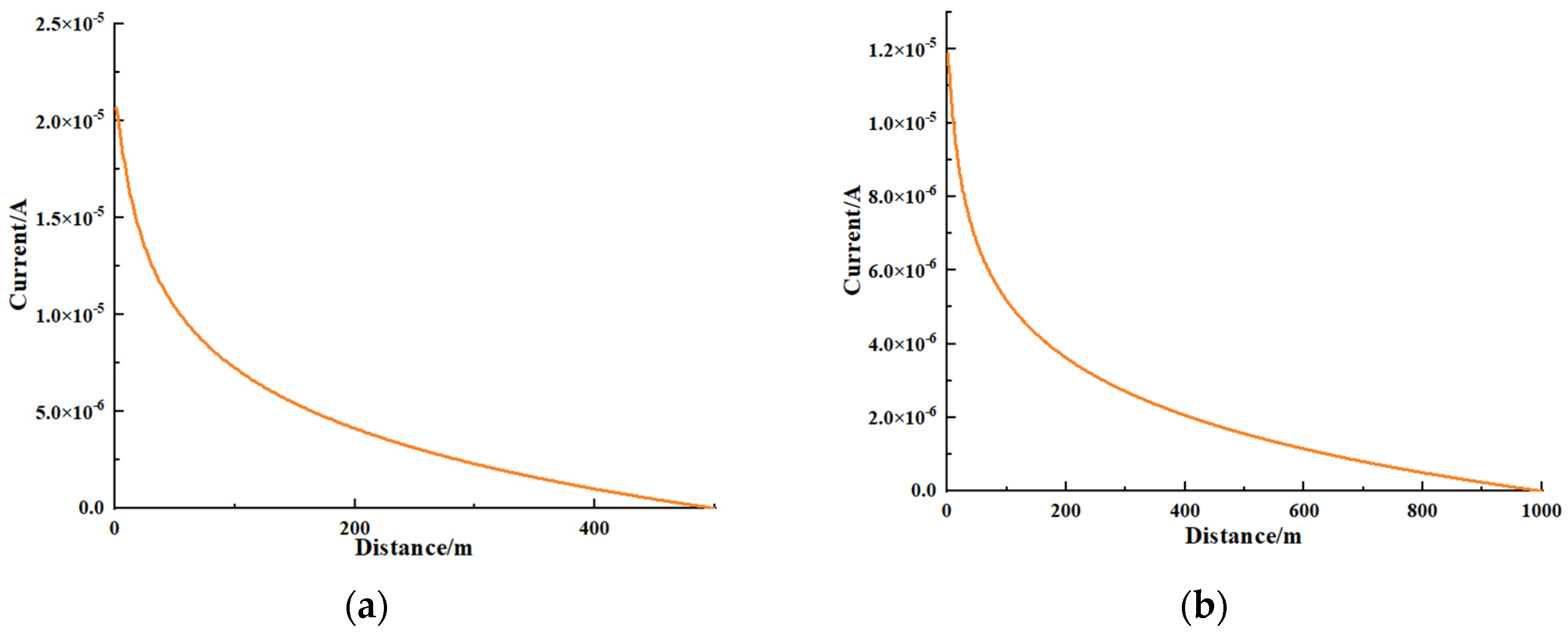
The current value at any point of the drill string is obtained, as shown in Figure 4. The distance between the two electrodes at the transmitting end is 10 m, the electrical conductivity of the rock and soil layer is 10−3 S/m, the drill string depth is 500 m and 1000 m, and the voltage of the transmitting end is 330 V, and the impedance Z is 3420 [29].
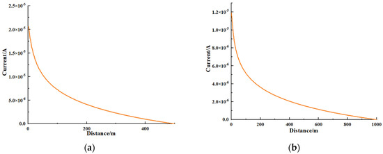
Figure 4.
Current at any point of bottom hole drill string: (a) H = 500; (b) H = 1000.
It can be seen from Figure 4 that under the condition of only changing the depth of the downhole drill string, the current value at any point on the drill string changes logarithmically with its position, and the closer to the bottom of the drill string, the greater the current loss in the rock and soil layer, and the smaller the current on the drill string. This has important reference significance for the position arrangement of the anisotropic magnetoresistance sensor in the actual measurement process.
2.2. Mathematical Model of Magnetic Field Distribution around Downhole Drill String
In order to further study the magnetic field distribution around the drill string in the new information downlink communication system based on anisotropic magnetoresistance technology, the magnetic field distribution around the downhole drill string is modeled. According to the theory of electromagnetic field and electromagnetic wave, it is known that the constant magnetic field is excited by constant current, which is another special form of the electromagnetic field. Considering the fact that the constant current and sum do not change with time, the basic equation integral form of the constant magnetic field is obtained from Maxwell’s equations, as shown in Equation (10):
The differential form is shown in Equation (11):
If the medium remains unchanged, Equation (12) can be obtained:
Equations (11) and (12) show that the constant magnetic field is passive and rotating, the constant current is the vortex source producing the constant magnetic field, and the magnetic line of force is the closed curve of the cross-chain with source current. There is usually a magnetization surface current on the interface of different magnetic media, and it mutates when it passes through the interface, and the interface satisfies Equation (13):
Equation (13) shows that the normal component on the interface is continuous. After the continuity of the normal component on the interface is known. If there is no free surface current () on the interface, the analysis on the interface shows that the relationship shown in Equation (14) is satisfied:
Equation (15) shows that the tangential component of magnetic field intensity is continuous. To facilitate the subsequent establishment and derivation of the magnetic field intensity model, the potential function is introduced. According to the boundary conditions , and on different media, the magnetic vector on different media is given by Equations (15) and (16):
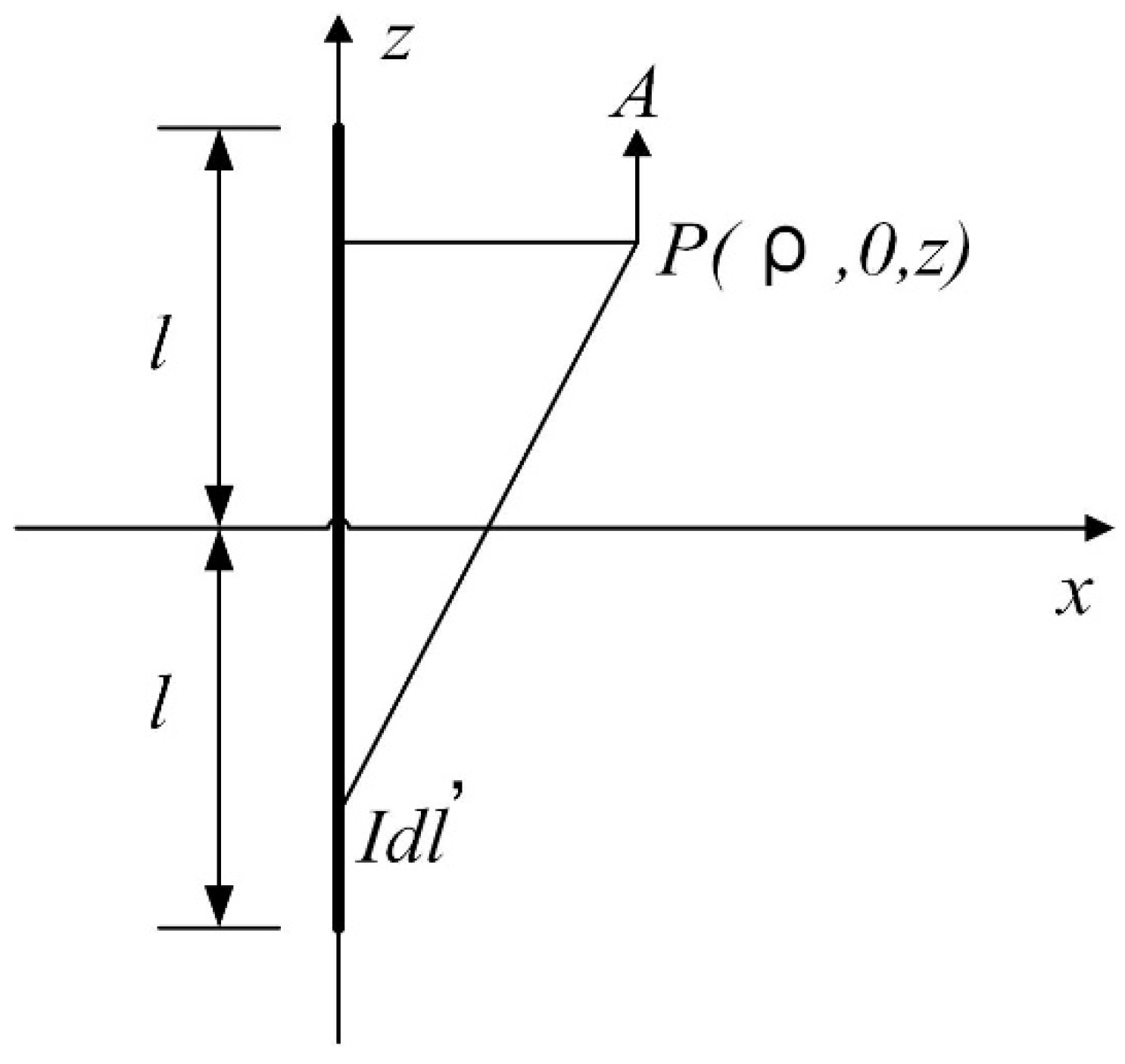
For a line with length of 2 , the vector magnetic potential of the current can be represented by a simplified model as shown in Figure 5.

Figure 5.
Vector magnetic quantity of linear current.
The vector magnetic potential generated by the current element satisfies the relationship described in Equation (17):
is vacuum permeability, .
By integrating the link , Equation (18) can be obtained:
At that time , Equation (18) can be simplified to Equation (19):
Because the magnetoresistance sensor is close to the drill string in the information downlink communication system based on anisotropic magnetoresistance technology, it can be introduced into the solution of space magnetic field. At that time , is infinite, that is, the vector magnetic potential of infinite linear current is infinite. In practice, infinite cannot be satisfied, the point (the reference point of the vector magnetic potential) is selected at , Equation (20) can be obtained:
.
Since a constant vector is added to the expression of , it does not affect the calculation of . Equation (20) can be simplified to Equation (21):
The corresponding magnetic induction intensity is shown in Equation (22):
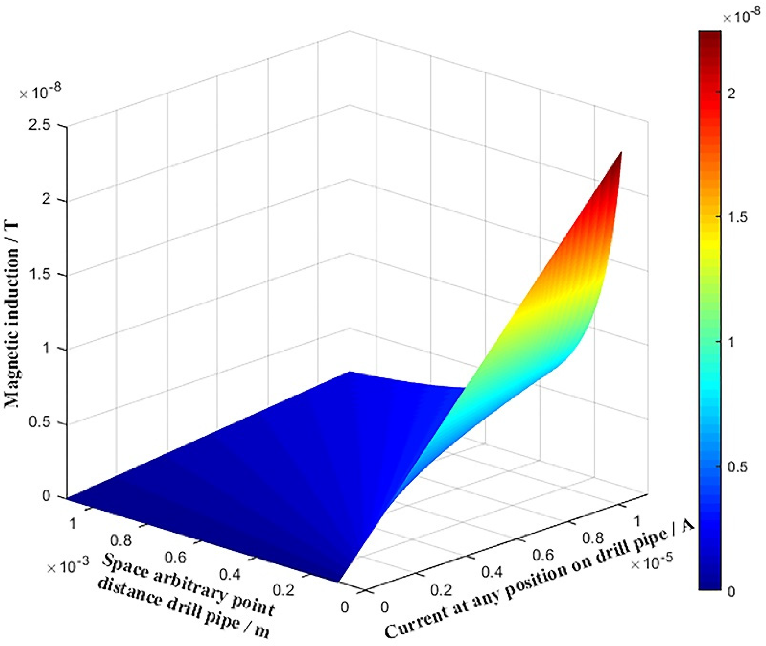
According to Equation (9), the magnetic induction intensity corresponding to drill string at depth a can be expressed by Equation (23):
In order to intuitively observe the corresponding magnetic induction intensity and current at any depth a on the drill string, the magnitude of magnetic induction intensity at any position within 1000 m of drill string depth and the changing trend of current size with depth are drawn, as shown in Figure 6. It can be seen from Figure 6 that when the current is constant, the closer the anisotropic magnetoresistance sensor is to the drill string, the greater the measured magnetic induction intensity B is.

Figure 6.
Magnetic induction intensity at any point of downhole drill string H = 1000 m.
3. Experimental Work
3.1. Design of Information Downlink Communication System While Drilling Based on Anisotropic Magnetoresistance Detection
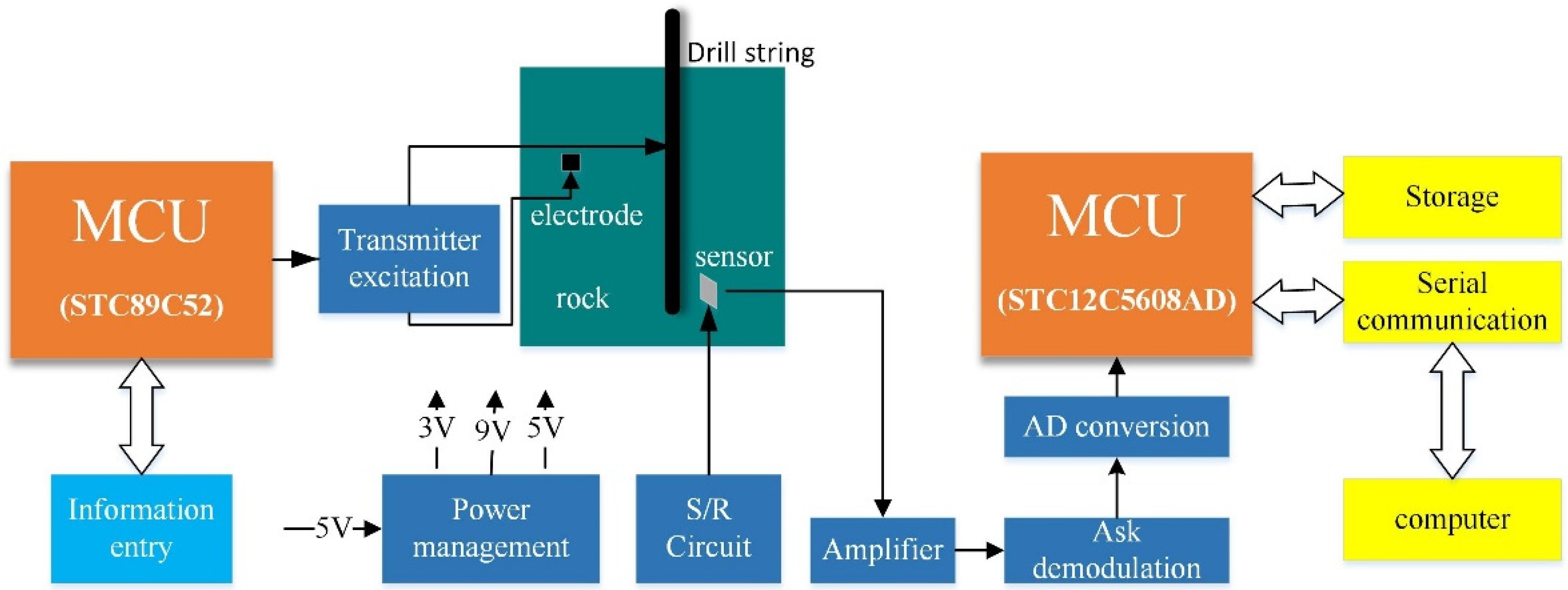
The whole system mainly includes the following parts: the transmitter includes the instruction sending circuit, processor, and signal excitation circuit; The receiver mainly includes the reluctance sensor and its position/reset circuit, amplifier circuit, ASK demodulation circuit, A/D acquisition circuit, processor, external clock reference circuit, a memory circuit, communication circuit. The overall framework is shown in Figure 7.

Figure 7.
Overall hardware block diagram of the system.
Due to the complexity of downhole conditions, the channel greatly impacts the transmission of code elements. Golay (23,12,7), the only nontrivial multi error correction complete code in the binary domain, is used to reduce the BER of the system. The system adopts pure software decoding mode, and the upper computer performs sampling decision and Golay (23,12,7) decoding operation according to the envelope data collected, which has strong portability.
3.2. Construction of Experimental Platform
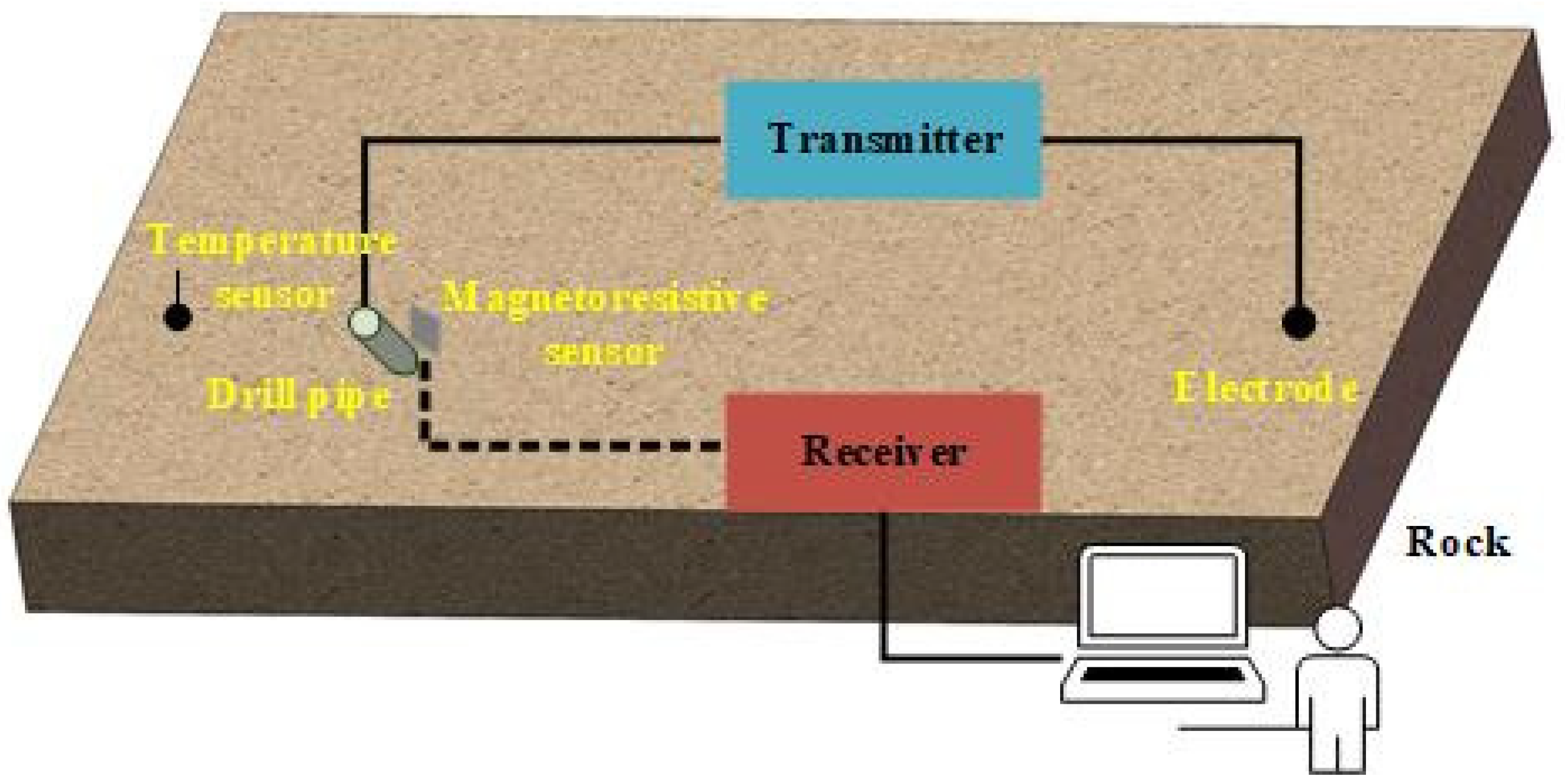
Considering that the communication system needs to be installed near the bit in practice and the complexity and high cost of the lifting and drilling process, it is a good choice to build an experimental simulation platform for pre-testing in the ground environment to verify the feasibility of the communication system based on anisotropic magnetoresistance detection. The model of the ground simulation experiment platform is shown in Figure 8.

Figure 8.
Simulation experiment platform model.
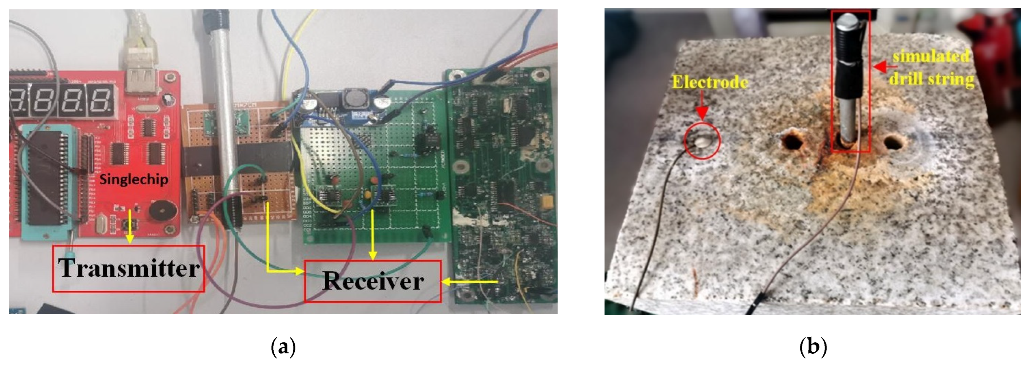
In the process of the experiment, the working process of the test platform is as follows: Firstly, the information to be transmitted is input into the transmitter. After coding, modulation, and other operations, the high-frequency carrier signal is taken as the carrier, and the signal is sent by the excitation module of the transmitter. Secondly, in the magnetoresistance sensor part, the magnetic field signal generated by the weak current signal is received by the magnetoresistance sensor, which is converted into voltage and transmitted to the receiver. Finally, after the receiver obtains the signal and a series of operations such as amplification, filtering, and decoding, the useful information carried by the signal is restored to realize wireless communication. In order to calculate the BER reasonably, the computer is used as the upper computer to receive and count the BER of the communication system. As a result, the experimental platform is built, as shown in Figure 9 and Figure 10.

Figure 9.
Each component of simulation experiment platform: (a) Circuit of the transmitter and the receiver; (b) Granite and the drill string.

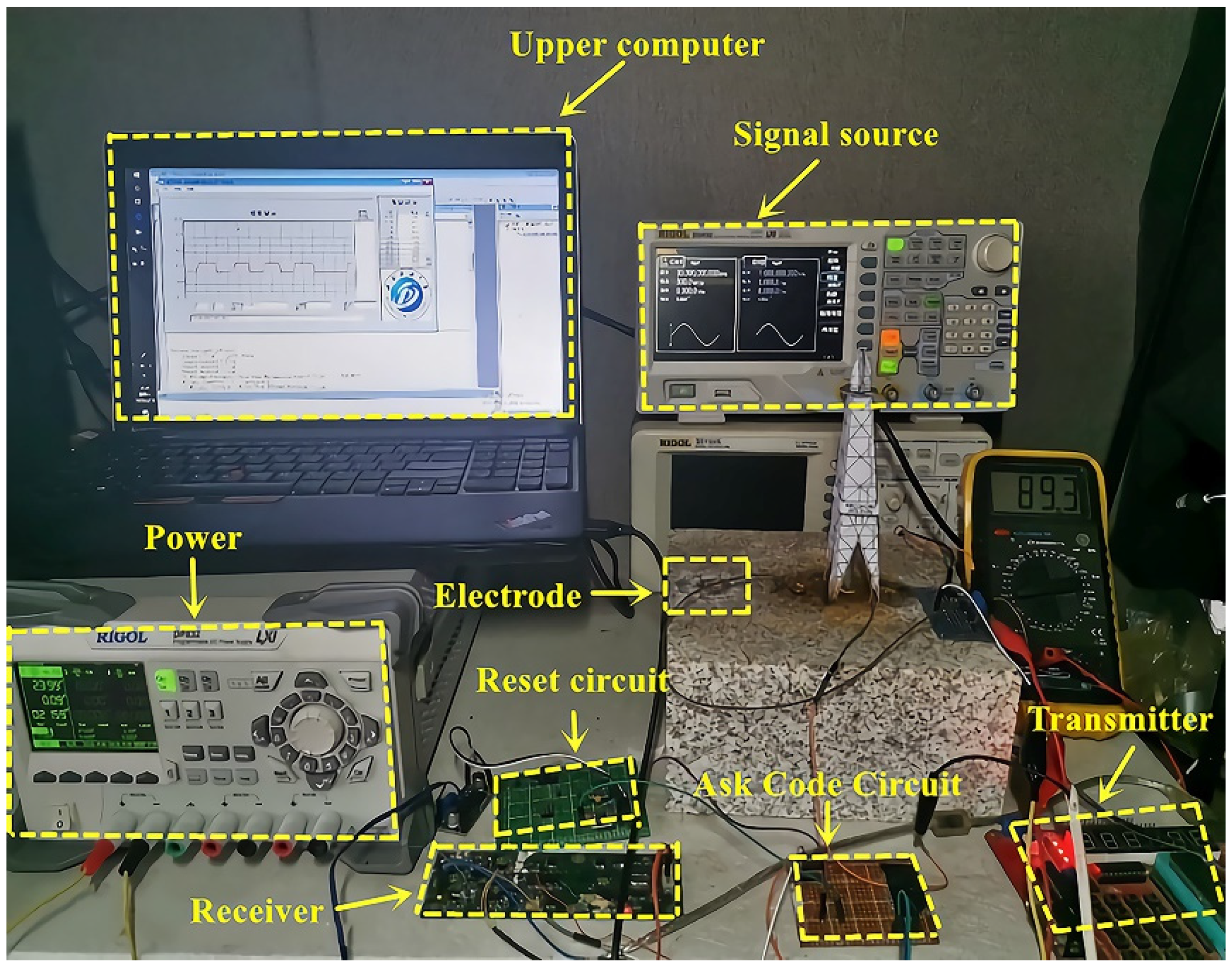
Figure 10.
Physical diagram of simulation experiment platform.
3.3. Experimental Design
Information transmission experiment is a complex operation, and it is easy to introduce errors, especially for the detection of weak signals. Nonstandard experimental operation is easy to have a negative impact on the experimental data. Therefore, in order to obtain high-quality experimental data, we must design a set of careful and effective experimental procedures. The system experiment is divided into two parts: the overall test experiment and the test experiment about influence factors of information download quality. During the experiment, the transmitter continuously sends data 170 (i.e., binary 10101010). The purpose of sending continuously the same data is to facilitate the statistics of BER and reduce the statistical error. The error rate of the evaluation index used in the experiment is the proportion of error data in every 12,600 data received. The experimental parameters and experimental methods are as follows:
Whole experiment: The overall experimental conditions are as follows: transmission voltage = 24 V, carrier frequency FZ = 30 kHz, baseband frequency FB = 1 kHz, interelectrode distance d = 5 cm, room temperature condition t = 25 °C. The BER data can be obtained and analyzed by changing the drilling depth.
Test experiment on the factors influencing the quality of information downlink communication: The single variable method is used to test the factors affecting the quality of information downlink communication. The transmission voltage, the distance between electrodes, and the working temperature are tested one by one, and the BER is obtained and analyzed.
4. Experimental Test and Analysis
4.1. Overall Test and Analysis of the System
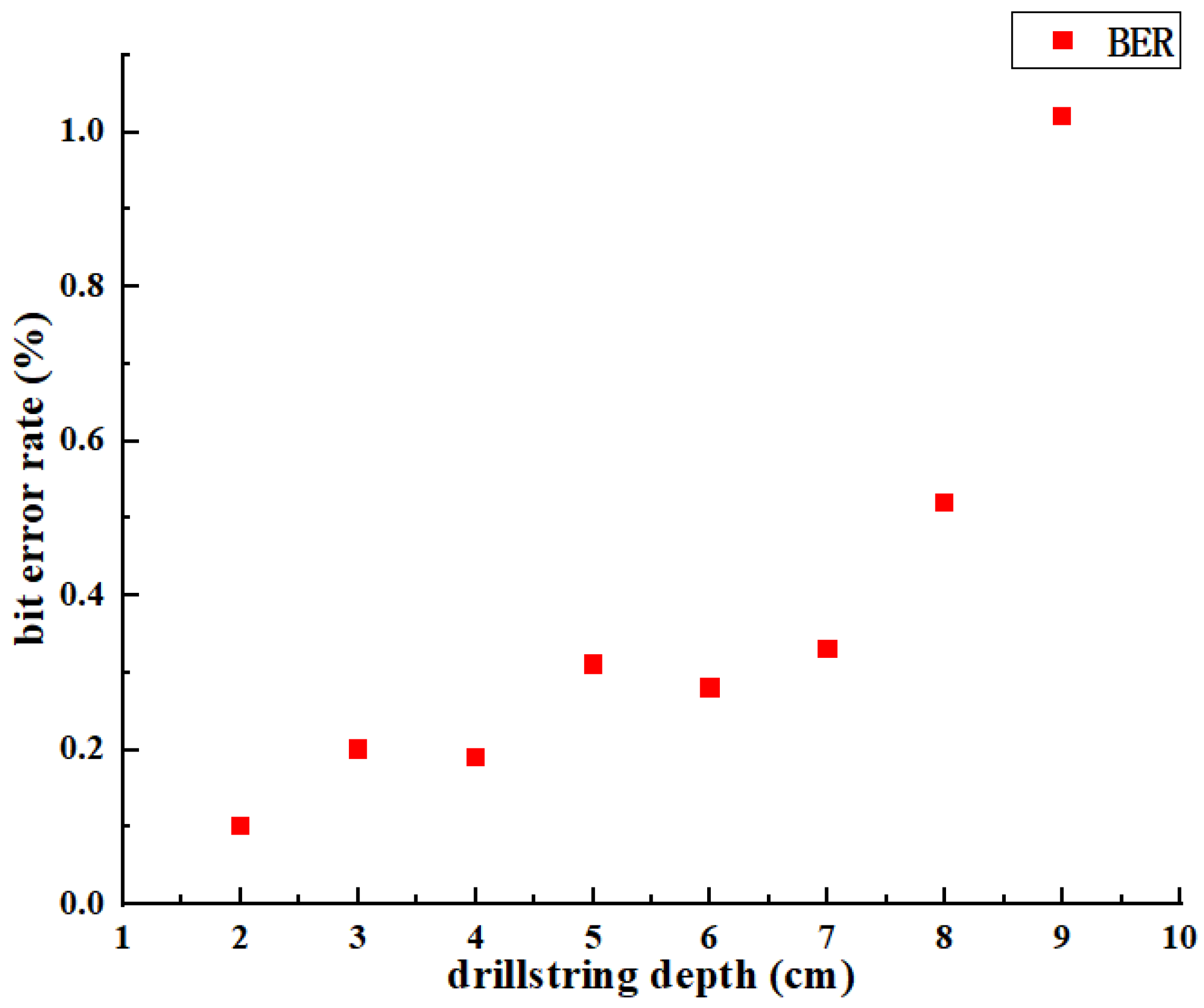
In order to verify the stability and reliability of electric current field signal transmission in the experimental system, the communication tests under different drilling depths (i.e., different communication distances) are carried out. The communication bandwidth is 30 kHz, and the data transmission rate is 1 kpbs. The test results are shown in Figure 11.
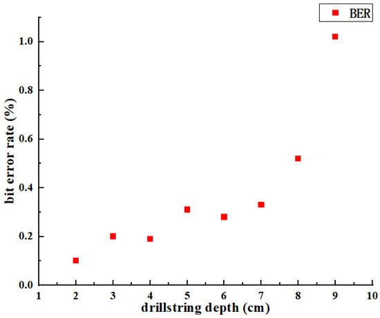
Figure 11.
Comparison of communication error rate under different communication distance.
It can be seen from Figure 11 that the larger the communication distance H is, and the greater the BER is. Under the above conditions, the communication BER is less than 0.31% when the communication distance is 1–5 cm, and the BER is about 1% when the drilling depth is 9 cm. When the drilling depth is greater than 7 cm, the BER of data transmission increases, and the change rate gradually increases with the increase of distance. The main reason for the above phenomenon is that the farther the voltage is transmitted, the more serious the loss of current in the rock layer will be, which makes the transmission current reduce and is easy to be interfered by external noise, resulting in the increase of BER. This problem can be solved by increasing the transmitting voltage and controlling the communication distance within the measurement accuracy of the anisotropic magnetoresistance sensor.
4.2. Test and Analysis of the Factors Affecting the Quality of Download
In order to further study the influence factors of downlink communication quality, the influence factors (emission voltage, electrode distances and temperature) were tested, respectively. The BER of the communication system under different transmission conditions is obtained, and the data results are analyzed to provide a reference for further reducing the BER.
4.2.1. Test under Different Transmitting Voltage
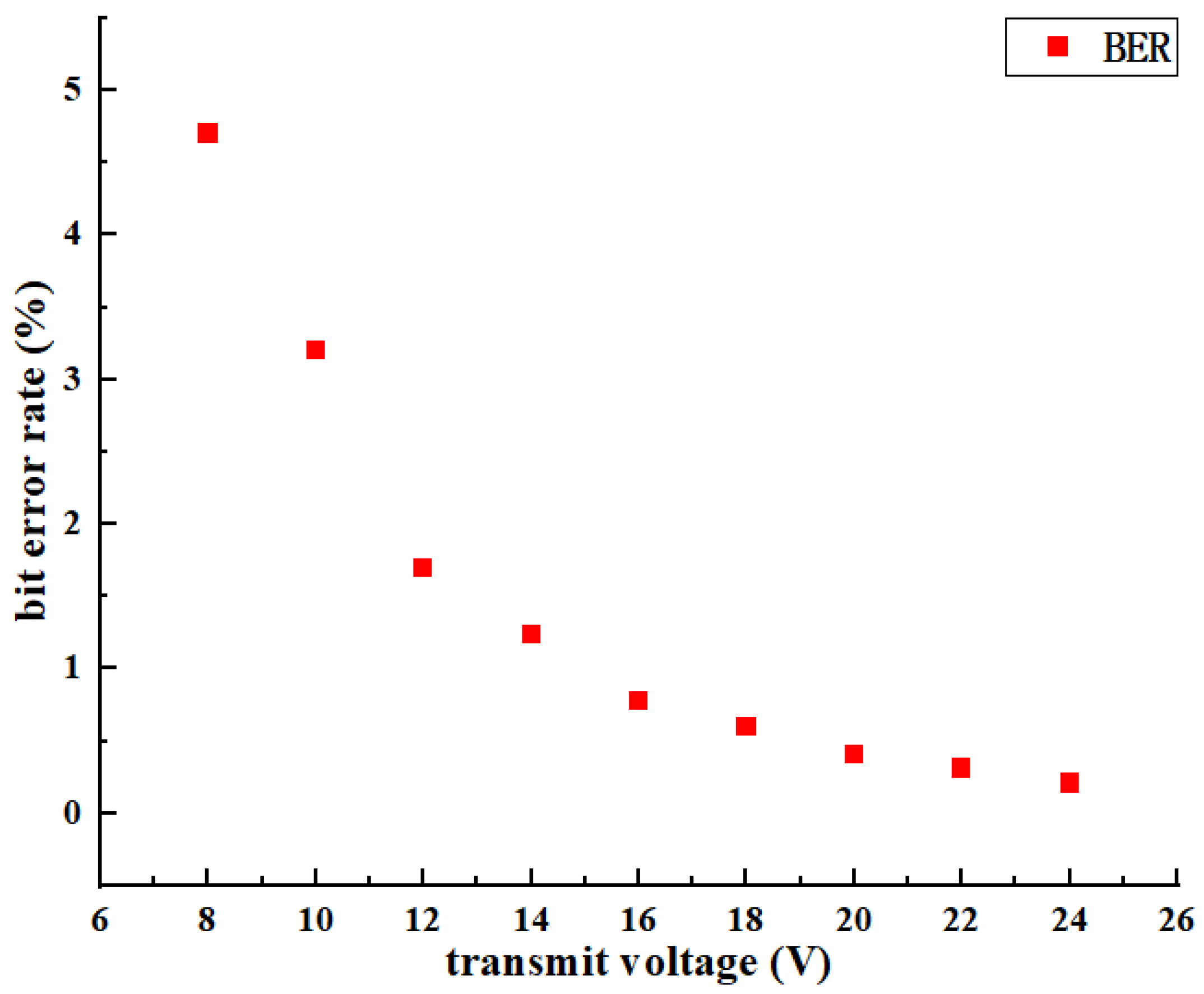
With other parameters unchanged, BER tests are conducted under different transmission voltage conditions, and the relationship between BER and transmit voltage is obtained as shown in Figure 12.
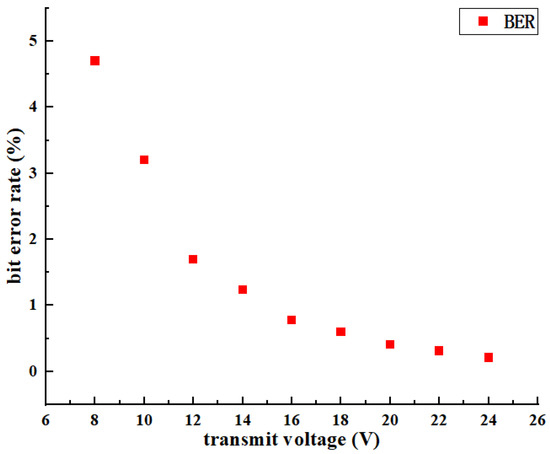
Figure 12.
Comparison of communication BER under different transmission voltage.
It can be seen from Figure 12 that the BER of information transmission decreases with the increase of transmitter voltage when other parameters are fixed. Increasing the transmitter voltage in the range of 6 V–16 V can significantly reduce the BER. When the transmitter voltage is increased in the range of 16 V–24 V, the BER still decreases, but the change is relatively slow. The result has demonstrated that the higher transmitting voltage of the transmitter, the greater current flowing through the simulated drill string, and the lower BER of the analog communication system, the more conducive to information transmission. In practical application, the transmitting voltage of the transmitter should be increased as much as possible within the range of allowable conditions.
4.2.2. Measurement under Different Distances(d) between Electrodes
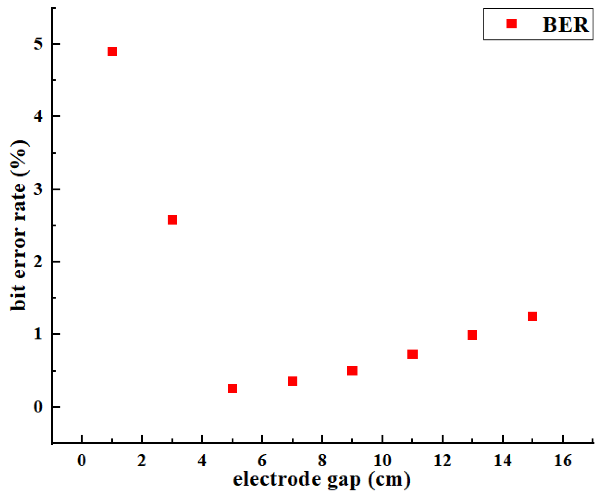
Keeping other parameters unchanged, different electrode distances were selected for the experimental test, and the relationship between BER and point electrode distance was obtained, as shown in Figure 13.
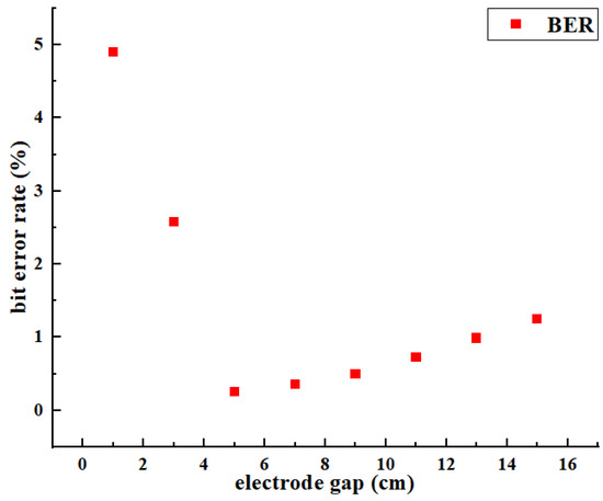
Figure 13.
BER comparison under different electrode distances.
As can be seen from Figure 13, fixed other parameters, the distance between electrodes is directly proportional to the transmission BER, that is, the smaller the distance between electrodes, the lower the BER of the analog communication system. In Figure 13, the BER when the distance between electrodes d = 5 cm and d = 8 cm is far less than that when the distance between electrodes is d = 10 cm and d = 15 cm. It can be seen that reducing the distance between electrodes is beneficial to reducing the BER of information transmission. However, when the distance between electrodes is too small, as shown in Figure 13, when d = 1 cm, the BER is greater than that generated by other electrode spacing. The result has demonstrated that the current flowing along the drill string decreases rapidly when the distance between the electrodes is too small, which leads to the low current at the bottom of the drill string, and the anisotropic magnetoresistance sensor cannot detect the magnetic field around the drill string, which leads to the increase of BER. It is suggested that the distance between electrodes should not be too large or too small in practical application. According to the experimental conditions in this paper, when the distance between electrodes is controlled about 5 cm, the BER of information transmission is the lowest.
4.2.3. Test at Different Temperatures
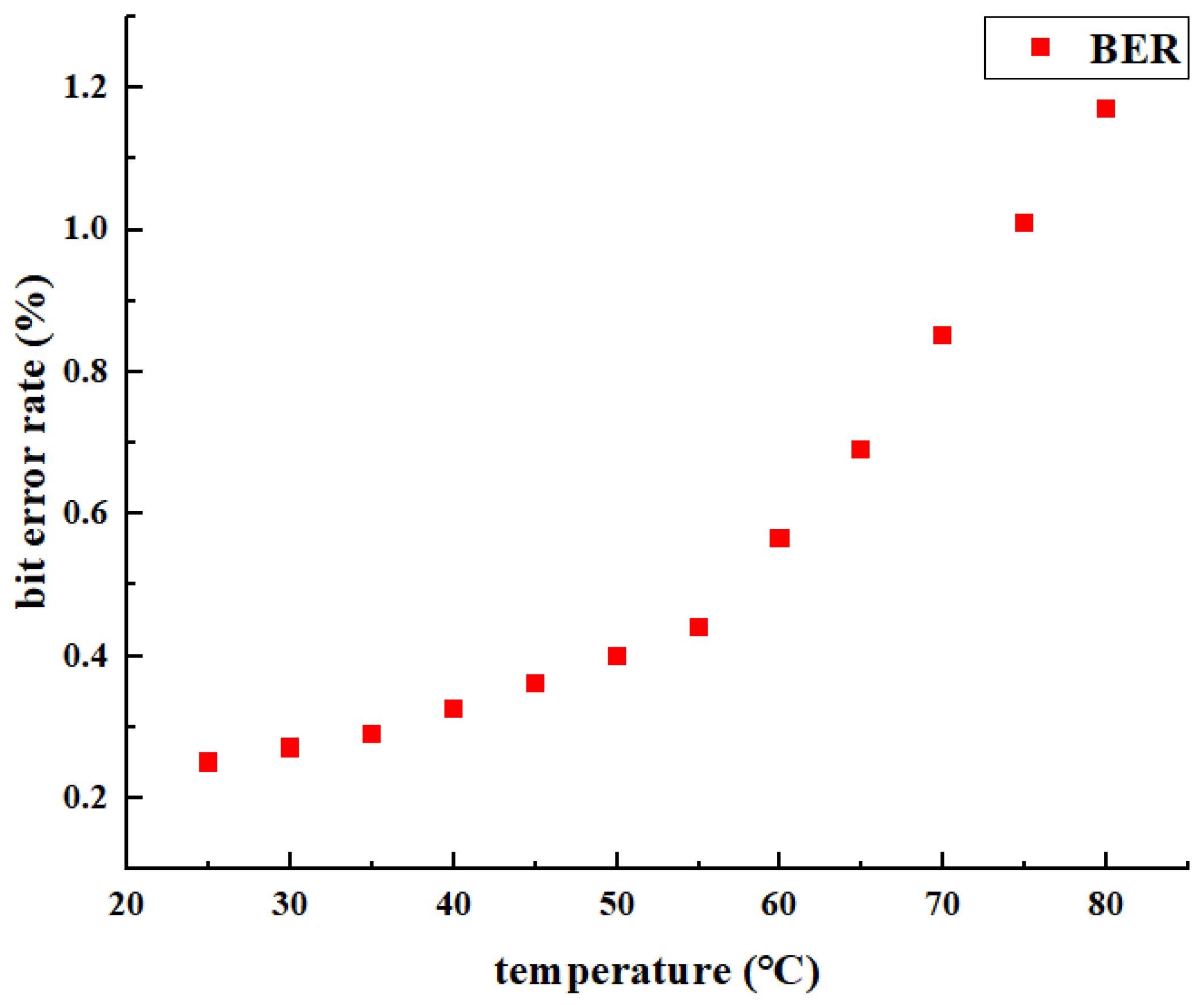
Keeping other parameters unchanged, the constant temperature box is used to change the ambient temperature, and representative temperature points are selected for the experiment, and the relationship between BER and ambient temperature is obtained, as shown in Figure 14.
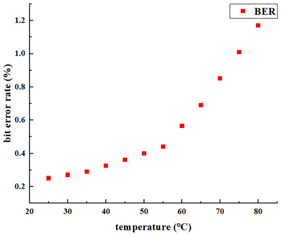
Figure 14.
BER comparison under different temperature conditions.
It can be seen from Figure 14 that the BER is 0.25% at room temperature of 25 °C, and 1.17% when the temperature rises to 80 °C. With the increase of the ambient temperature, the BER of the detection system is monotonically increasing, and the change rate is gradually increasing. The result has demonstrated that the temperature increases, which leads to the decrease of sensor sensitivity and the decrease of output voltage, which makes the BER of communication system increase. In practical application, the temperature adaptive compensation method is usually used to effectively reduce or eliminate the impact of environmental temperature changes.
5. Conclusions
Based on the analysis of the principle of anisotropic magnetoresistance detection and the theory of downhole electric current field, a new technology of downlink communication while drilling technology is studied in this paper. The communication technology is first used in the process of information downlink communication while drilling. It has the advantages of fast communication speed, low BER, simple structure, convenient implementation, and low cost. Through the experimental studies, the following conclusions can be drawn:
- In order to study the structure of the underground wireless communication system, the system structure model is established; at the same time, the current distribution model and magnetic field distribution model of different positions of downhole power drill string are established based on the anisotropic magnetoresistance detection principle and downhole electric current field theory. The design of the laboratory prototype of the downlink communication system based on anisotropic magnetoresistance is realized
- To verify the feasibility of the proposed information downlink communication technology while drilling, a ground experimental platform simulating the downhole communication state is built, and the principle prototype is tested. The test results show that when the communication distance is 9 cm and the data transmission rate is 1 kbps, the maximum BER of the simulation system based on anisotropic magnetoresistance detection is
- For the purpose of further analyzing the influence factors of downlink communication quality, the emission voltage, the distance between electrodes, and the working temperature are tested and analyzed. The experimental data show that the transmission voltage and the temperature of the test environment have great impacts on the experimental BER, which provides a reference for further reducing the BER and ideas for optimizing the technology of downlink information communication while drilling
- Although the system has completed the theoretical research and realized the small-scale model verification, it is still in the laboratory application stage and has certain limitations, such as: no study on the effect of rock properties. In the future work, the in-situ verification experiment of complex downhole conditions will be carried out to further enhance its application value.
Author Contributions
Conceptualization, L.G.; methodology, L.G., L.Z. and Y.H.; software, H.L. and X.X.; validation, L.G., L.Z. and Y.H.; formal analysis, L.Z. and Y.H.; data curation, L.Z. and H.L.; writing—original draft preparation, L.G., X.X. and Y.H.; writing—review and editing, L.G., L.Z. and C.Y. All authors have read and agreed to the published version of the manuscript.
Funding
This work is supported by the National Natural Science Foundation (51974273), the International Science and Technology Cooperation Project of Chengdu (2020-GH02-00016-HZ), and the Special Project of Science and Technology Strategic Cooperation between Nanchong City and Southwest Petroleum University (SXHZ026/SXHZ038).
Institutional Review Board Statement
Not applicable.
Informed Consent Statement
Not applicable.
Data Availability Statement
Not applicable.
Conflicts of Interest
The authors declare no conflict of interest.
References
- Maciej, M. Energy Security in Danger? A Comparative Analysis of Oil and Copper Supply. Energies 2022, 15, 560. [Google Scholar]
- Kostarev, S.N.; Sereda, T.G. Development of software and hardware models of monitoring, control, and data transfer to improve safety of downhole motor during drilling. In Proceedings of the International Conference on Innovations and Prospects of Development of Mining Machinery and Electrical Engineering (IPDME), Saint Petersburg, Russia, 23–25 March 2017. [Google Scholar]
- Dang, R.R.; Yin, G.; Gao, G.W.; Lu, L. Development of downlink communication system for steerable drilling application. Procedia Eng. 2011, 24, 319–323. [Google Scholar]
- Vodrazka, J. Potential of communication cables in industry for gigabit transmission rates. In Proceedings of the International Conference on Information and Digital Technologies, Zilina, Slovakia, 7–9 July 2015. [Google Scholar]
- Du, C.; Zhang, F.; Ma, S.; Tang, Y.X.; Li, H.; Wang, H.M.; Li, S.Y. Secure transmission for downlink NOMA visible light communication networks. IEEE Access 2019, 7, 65332–65341. [Google Scholar] [CrossRef]
- Hu, Z.; Xie, X.H.; Ge, L.; Xu, H.; Gu, S.C. The research on the establishment and simulation of intelligent drill string cables based on nonuniform transmission line theory. J. Residuals Sci. Technol. 2017, 14, 31–40. [Google Scholar]
- Su, Y.; Qi, X.; Liu, Y.; Zhang, J.G. Electromagnetic measurement while drilling technology based on the carrier communication principle. Pet. Explor. Dev. 2013, 40, 242–248. [Google Scholar] [CrossRef]
- Gao, L.; Gardner, W.; Robbins, C. Limits on data communication along the drill string using acoustic waves. SPE Reserv. Eval. Eng. 2008, 11, 141–146. [Google Scholar] [CrossRef]
- Zhao, J.B.; Chen, R.M.; Li, X.J. Research on Bottom Hole Data Transmission Technology. Digit. Technol. Appl. 2015, 2, 33–34. [Google Scholar]
- Berro, M.J.; Reic, M. Laboratory investigations of a hybrid mud pulse telemetry (HMPT)–A new approach for speeding up the transmitting of MWD/LWD data in deep boreholes. J. Pet. Sci. Eng. 2019, 183, 106374. [Google Scholar] [CrossRef]
- Xue, M.Q.; Rong, L.L. Analysis on the application status and prospect of LWD data transmission technology. Chem. Enterp. Manag. 2019, 24, 87–88. [Google Scholar]
- Yue, S.; Yinao, S.; Gensheng, L.; Lin, L.; Shouceng, T. Transmission characteristics of DPSK mud pressure signals in a straight well. Pet. Sci. Technol. 2011, 12, 1249–1256. [Google Scholar] [CrossRef]
- Liu, Q.Y.; Zhang, A.Q.; Li, W. Application and development of RFID technology in downhole tools. Oil Field Mach. 2015, 44, 61–66. [Google Scholar]
- Ma, D.; Shi, Y.B.; Zhang, W.; Liu, G.Z. Performance analysis of V-OFDM for acoustic communication along drill strings. IET Commun. 2017, 11, 576–583. [Google Scholar] [CrossRef]
- Ge, L.; He, Y.; Tian, G.Y.; Wei, G.H.; Ahmed, J.; Deng, H.X.; Huang, Q. Measurement of annular flow for drilling engineering by electromagnetic flowmeter based on double-frequency excitation. J. Sens. 2019, 2019, 4090632. [Google Scholar] [CrossRef] [Green Version]
- Salem, S.I.; Schultz, C.W.; Rabbani, B.A.; Tsutsui, R.T. Splitting of the 4d3/2 and 4d5/2 levels in rare-earth elements. Phys. Revie Lett. 1971, 27, 477–478. [Google Scholar] [CrossRef]
- Kim, C.W.; Lee, E.; Syed, N.A.A. Channel characterization for underwater electric conduction communications systems. In Proceedings of the OCEANS 2010 MTS/IEEE SEATTLE, Seattle, WA, USA, 20–23 September 2010; pp. 1–6. [Google Scholar] [CrossRef]
- Xiang, X.; Luo, Y.; Yi, K.C.; Zhang, Z.L.; Tian, H.X.; Wang, J.K. Communication channel analysis of penetrating underground current Field in rock formation. Coal Field Geol. Explor. 2005, 33, 77–79. [Google Scholar]
- Yang, T.H.; Yi, K.C.; Tia, H.X. Weak signal acquisition algorithm for ground-through wireless communication. Signal Process. 2017, 33, 978–984. [Google Scholar]
- Ge, L.; Chen, J.X.; Tian, G.Y.; Zeng, W.; Huang, Q.; Hu, Z. Study on a new electromagnetic flow measurement technology based on differential correlation detection. Sensors 2020, 20, 2489. [Google Scholar] [CrossRef]
- Nibir, S.J.; Parkhideh, B. Magnetoresistor with planar magnetic concentrator as wideband contactless current sensor for power electronics applications. IEEE Trans. Ind. Electron. 2018, 65, 2766–2774. [Google Scholar] [CrossRef]
- Quynh, L.K.; Tu, B.D.; Anh, C.V.; Duc, N.H.; Phung, A.T.; Dung, T.T.; Giang, D.H. Design optimization of an anisotropic magnetoresistance sensor for detection of magnetic nanoparticles. J. Electron. Mater. 2019, 48, 997–1004. [Google Scholar] [CrossRef]
- Mlejnek, P.; Vopalensky, M.; Ripka, P. AMR current measurement device. Sens. Actuators A Phys. 2008, 141, 649–653. [Google Scholar] [CrossRef]
- Díaz-Michelena, M.; Cobos, P.; Aroca, C. Lock-in amplifiers for AMR sensors. Sens. Actuators A Phys. 2015, 222, 149–159. [Google Scholar] [CrossRef] [Green Version]
- Ge, L.; Deng, H.X.; Wang, Q.; Hu, Z.; Li, J.L. Study of the influence of temperature on the measurement accuracy of transit-time ultrasonic flowmeters. Sens. Rev. 2019, 39, 269–276. [Google Scholar] [CrossRef]
- Grcev, L.; Popov, M. On high-frequency circuit equivalents of a vertical ground rod. IEEE Trans. Power Deliv. 2005, 20, 1598–1603. [Google Scholar] [CrossRef] [Green Version]
- Bataller, V.; Muñoz, A.; Gaudó, P.M.; Mediano, A.J.; Cuchí, A.; Villarroel, J.L. Earth impedance model for through-the-earth communication applications with electrodes. Radio Sci. 2010, 45, RS6015. [Google Scholar] [CrossRef]
- Ralchenko, M.; Roper, M.; Samson, C.; Svilans, M. Near-field VLF electromagnetic signal propagation in multistory buildings. IEEE Trans. Antennas Propag. 2017, 66, 848–856. [Google Scholar] [CrossRef]
- Dias, C.A. Developments in a model describe low-frequency electrical polarization of rocks. Geophysics 2000, 65, 437–451. [Google Scholar] [CrossRef]


Publisher’s Note: MDPI stays neutral with regard to jurisdictional claims in published maps and institutional affiliations. |
© 2022 by the authors. Licensee MDPI, Basel, Switzerland. This article is an open access article distributed under the terms and conditions of the Creative Commons Attribution (CC BY) license (https://creativecommons.org/licenses/by/4.0/).