Article

Study of Tower Clearance Safety Protection during Extreme Gust Based on Wind Turbine Monitoring Data

1
College of Mechanics and Materials, Hohai University, Nanjing 211100, China
2
Wind Turbine Structural Engineering Research Center of Jiangsu Province, Nanjing 211100, China
3
College of Energy and Electrical Engineering, Hohai University, Nanjing 211100, China
*
Author to whom correspondence should be addressed.
Energies 2022, 15(12), 4400; https://doi.org/10.3390/en15124400
Submission received: 6 May 2022 / Revised: 6 June 2022 / Accepted: 14 June 2022 / Published: 16 June 2022
(This article belongs to the Special Issue Theoretical and Technical Challenges in Offshore Wind Power)

Abstract

:
Large-scale wind turbines often face the problem of tower clearance safety under extreme gust conditions. Since gust intensity is positively correlated with the change rate of the generator’s speed, a gust identification method is proposed based on wind turbine monitoring data. Furthermore, a novel tower clearance safety protection strategy is proposed, which superimposes some additional speed requirements on the basis of normal pitch rate when identifying extreme gust so as to alleviate the dynamic response of the wind turbine. Simulations and comparison of a 5 MW wind turbine, before and after applying the new strategy, showed that the new strategy can induce an increase in pitch angle for the wind turbine and, simultaneously, avoids the emergency stop caused by the generator’s overspeed. Meanwhile, when the new strategy is adopted, the blade tip’s deformation and the load on the top of the tower are reduced by 19.9% and 52.2%, respectively. Therefore, the proposed strategy can not only protect the safety of the wind turbine but it also reduces costs.

1. Introduction

The single capacity of wind turbines has grown by nearly 30 times since 1985, and wind turbines’ diameter has also increased rapidly, and this growth trend will continue [1,2,3]. Due to the national carbon peak and carbon neutral strategy, many new wind turbine products have emerged in China in the past few years, and the blade lengths of those wind turbines normally exceed 80 m, while some even reach 100 m. With the blade length’s increase, the blade’s flexibility also increases, and the deformation of flexible blade under aerodynamic loads will be greater [4,5]. Therefore, tower clearance often has difficulty in meeting the requirements of the minimum safety distance under extreme gust condition, and wind turbines are facing a failure risk [6,7]. Tower clearance is related to multiple factors, including structural parameters such as blade pre-bend, rotor cone and tilt angle, overhang, and the control method during wind turbine operations.
By changing the structural parameters of a wind turbine, for example, increasing the cone angle and tilt angle of the rotor, tower clearance can be significantly increased. However, this often reduces the effective sweeping area of the rotor, resulting in power reduction. Therefore, research on the tower clearance safety protection usually needs to consider the adjustments of wind turbine structural parameters and control strategies simultaneously. In order to control the adverse impact of extreme gust on tower clearance during the operation of large-scale wind turbine, researchers have also completed numerous studies. Applying a novel fine pitch strategy that varies the fine pitch setting according to the shaft power does not only increase the tower clearance during extreme gust but also reduces fatigue loads [8,9]. This method is actually a kind of power de-rating strategy; thus, its disadvantage is that it will also reduce the power generation of wind turbines under normal operating conditions. References [10,11,12] introduce smart rotor control methods to alleviate the dynamic response of a wind turbine under extreme conditions. However, this method usually requires the installation of additional adjustment structures on the blades; thus, its application is difficult.
The energy conversion process and wind turbine loads come from the interaction between the wind and blades, since wind directly influences the dynamic behavior of wind turbines. If wind speed (gust) is known, the control algorithm can be significantly improved [13]. Therefore, many studies focus on this direction, where wind speed can be obtained by direct measurements or indirect estimations. For direct measurement, the mechanical anemometer on the nacelle provides measurement data for the wind turbine controller. However, the wind speed measured in the nacelle is not suitable for control since the nacelle measurement is highly disturbed by the blades. In addition, extreme gusts can be accurately calculated by light detection and ranging (LIDAR) wind measurements [14,15,16,17,18]. However, wind speed varies with the site; thus, each wind turbine needs to be measured individually, and the extensive use of LIDAR will increase costs. As for indirect estimate, there are also some researchers that introduce a method of wind speed reconstruction based on rotor speed and power efficiency [19,20,21,22]. These studies are progressing, but they usually require a long estimation period; therefore, the effect of suppressing the dynamic response caused by extreme gust is poor [22,23]. References [24,25] estimate the effective wind speed and inflow angle through a nonlinear observer based on measuring the bending moment in the flap and edge direction of the blade’s root, and they propose quick pitch strategies that effectively enhance tower clearance. However, installing strain gauges at the blade’s root is uncommon.
By conducting further studies on the dynamic performance of wind turbines under extreme gust conditions, it can be found that the generator speed of the wind turbine increases rapidly. This phenomenon indicates that there may be a positive correlation between the change rate of the generator speed and gust. Through the mathematical model analysis of the wind turbine in Section 2.1, this speculation is confirmed. Therefore, this paper proposes a novel extreme gust identification method based on wind turbine monitoring data, which infers the gust’s amplitude according to the change rate of the generator speed. In addition, during extreme gust conditions, the rapid increase in generator speeds may trigger the overspeed protection of the wind turbine and lead to emergency shutdowns. In addition, the coupling effect of an emergency shutdown and extreme gusts often results in extreme load and minimum tower clearance of the wind turbine. In this case, a new wind turbine control strategy under extreme gust conditions is proposed in Section 2.2. A certain overshoot is superimposed on the basis of the normal pitch rate when extreme gust is identified, which can solve the problem of the relatively slow pitch rate due to the larger rotor inertia of large-scale wind turbines. The energy absorbed by the wind turbine can then be rapidly reduced, and the increasing trend of generator speed is suppressed. The proposed gust identification method and gust control strategy are simulated and verified in Section 3, using a 5 MW wind turbine as an example. The simulation results show that the proposed method can effectively enhance the tower’s clearance. The conclusions are finally provided in Section 4.

2. Method

2.1. Gust Identification Method

A wind turbine mainly consists of a rotor, gearbox, generator, and other components. The energy transfer path of the wind turbine is determined by the wind acting on the blades to generate aerodynamic force, which is then converted into mechanical energy to drive the mainshaft rotation. The mainshaft is connected to the generator through the gearbox, and then electric energy is generated by the generator and outputted into the grid. Figure 1 is a simplified model of a wind turbine system; in this model, it is assumed that the gearbox is a rigid structure and the low-speed shaft has rotational inertia, a viscous damper, and a viscous dampened spring. In addition, the model includes a high-speed shaft for which its model consists of the moment of inertia at the high-speed shaft’s side (the generator side) [22].
The mathematical equation for the model shown in Figure 1 is as follows:
J r ω ˙ r = τ r K θ θ B θ + B r ω r + B θ N g ω g
J g ω ˙ g = η d t K θ N g θ + η d t B θ N g ω r η d t B θ N g 2 + B g ω g τ g
θ ˙ = ω r 1 N g ω g
where
  • J r 
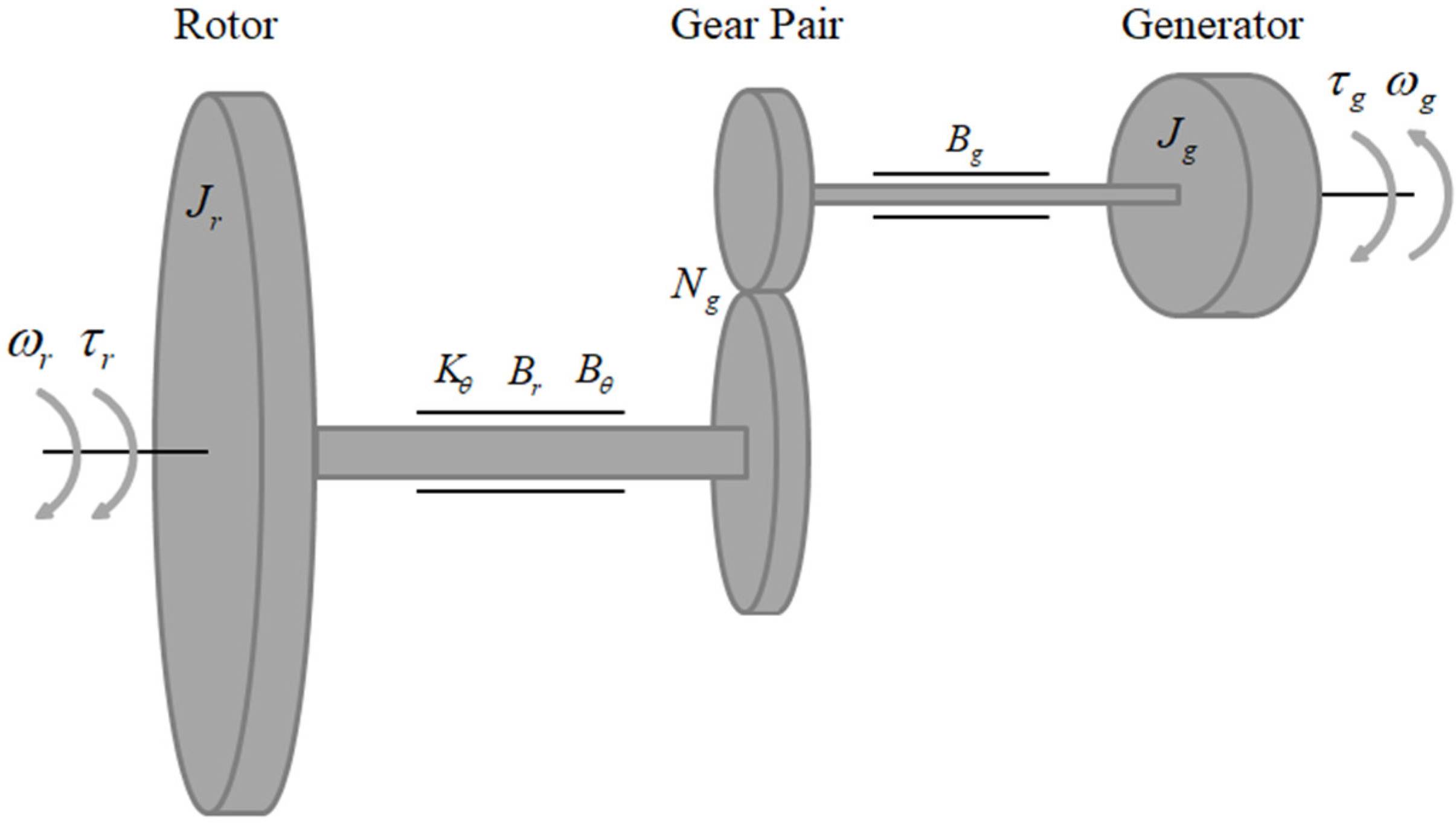
is the moment inertia of the rotor (kg·m2);
  • ω r is the rotor’s speed (rad/s);
  • τ r is the aerodynamic torque (N.m/rad);
  • K θ is the torsional rigidity (N.m/rad);
  • θ is the torsion angle of the mainshaft (rad);
  • B θ is the torsion damper (kg·m2/rad·s);
  • B r is the viscous friction force at the rotor side (kg·m2/rad·s);
  • N g is the gearbox’s transmission ratio;
  • ω g is the generator’s speed (rad/s);
  • τ g is the generator’s electromagnetic torque (N.m);
  • J g is the moment inertia of the high-speed shaft (kg·m2);
  • η d t is the efficiency of the wind turbine transmission system;
  • B g is the viscous friction force of the generator side (kg·m2/rad·s).
Equation (2) can be simplified and the efficiency loss of the wind turbine drivetrain system can be expressed by τ 1 as follows.
J g ω ˙ g = K θ N g θ + B θ N g ω r B θ N g 2 + B g ω g τ g τ 1
Since the dynamic model of the transmission chain has a low influence on the wind speed estimation of wind turbines, it is typically not considered in gust intensity prediction methods. Therefore, Equations (1) and (4) can be simplified as follows.
J t ω ˙ g = τ r N g τ g τ 1
J t = J r + N g 2 J g
The aerodynamic torque of the rotor is expressed as follows.
τ r = ρ π R 2 v r 3 C p λ , β 2 ω r
where ρ is the air density (kg/m3), R is the radius of the rotor (m), v r is the effective wind speed (m/s), C p λ , β is the wind turbine power utilization coefficient, λ is the blade tip speed ratio, and β is the pitch angle.
Equation (5) can be expressed as follows.
ω ˙ g = ρ π R 2 v r 3 C p λ , β 2 ω r N g τ g τ 1 / ( J r + N g 2 J g )
It can be observed from Equation (8) that the change rate of the generator’s speed ω ˙ g is mainly related to wind speed v r , rotor speed ω r , and the generator electromagnetic torque τ g . However, only wind speed has a cubic relationship with the change rate of the generator speed. In the pitch control stage, τ g and ω r are constant; thus, wind speed is positively correlated with the change rate of the generator’s speed, which is described as follows:
ω ˙ g = v r 3 K
where K is the coherence coefficient.
Therefore, gust intensity can be identified according to the change rate of the generator’s speed.

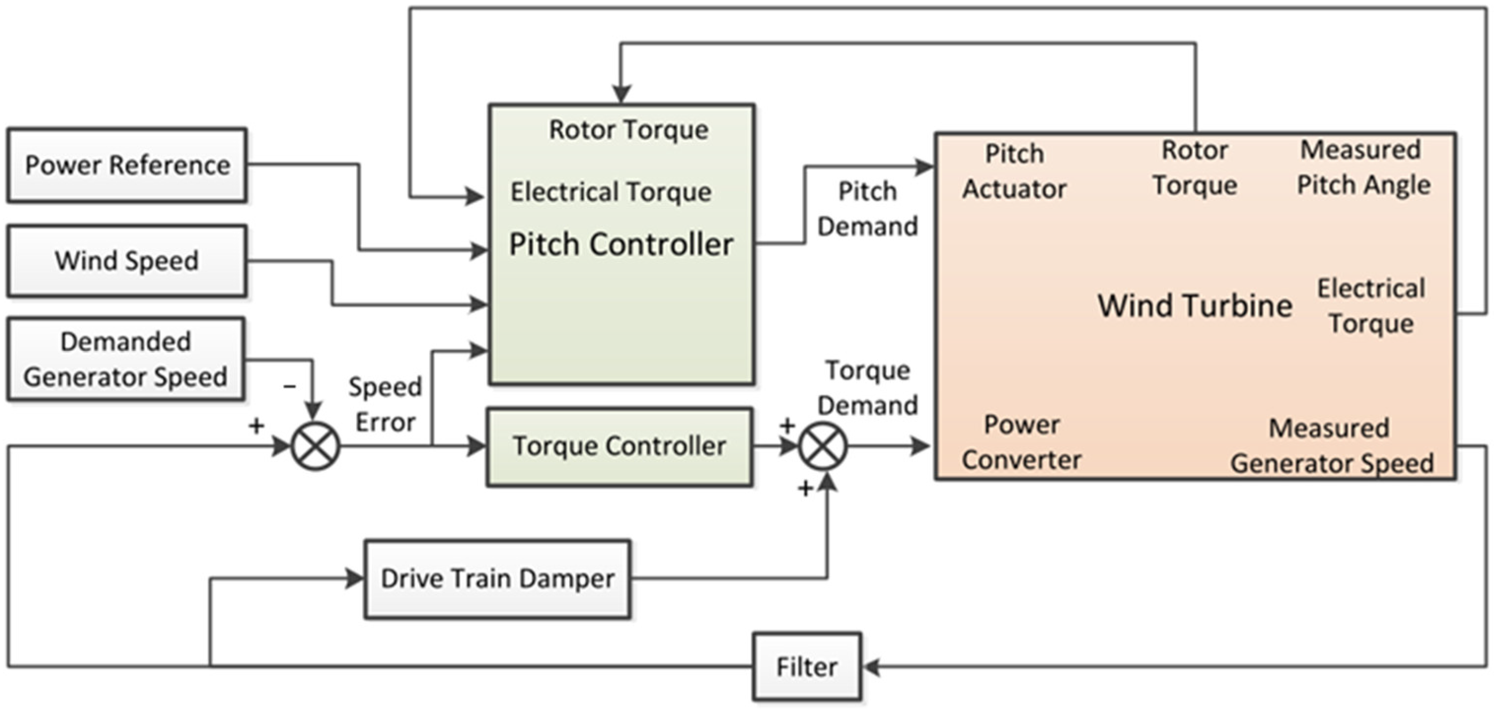
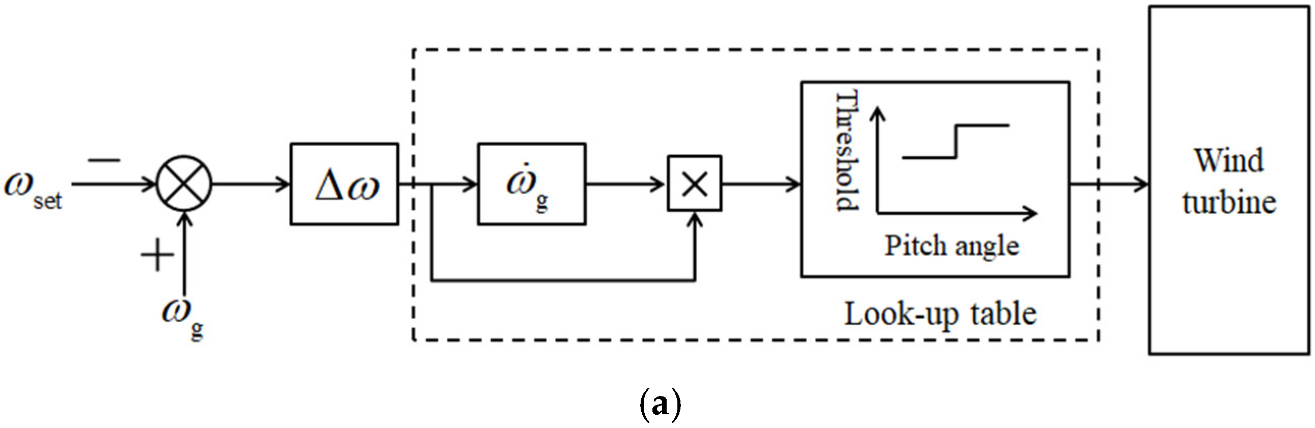
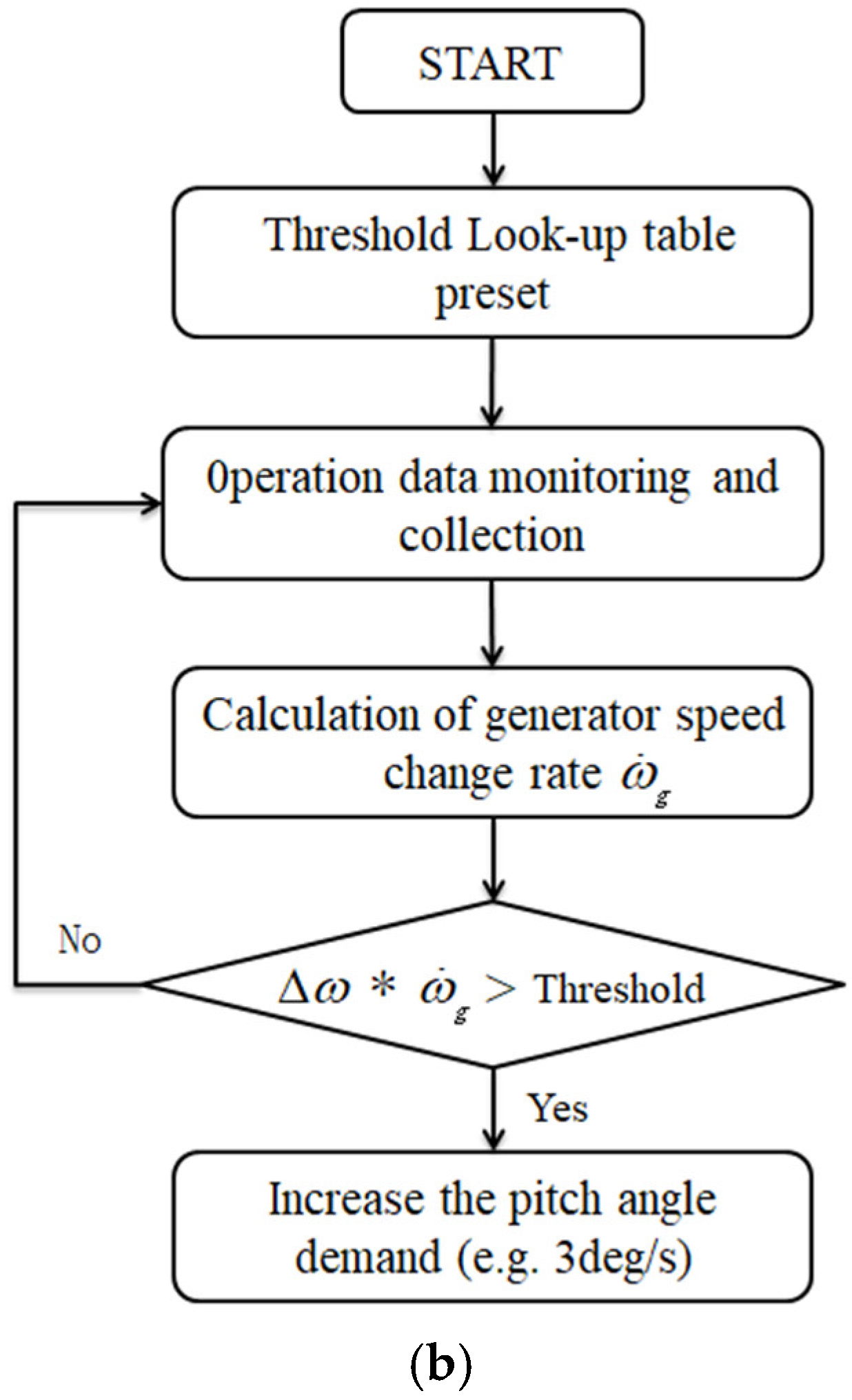
2.2. Tower Clearance Safety Protection Strategy

The wind turbine controller is usually composed of torque controller, pitch controller, and filter, as shown in Figure 2. The pitch controller works above the rated wind speed, and its purpose is to adjust the generator’s speed. The pitch controller is usually designed as a PI controller with the generator speed difference as an input and pitch angle as the output [26,27]. Due to the nonlinear characteristics of the blade’s aerodynamics, the proportional coefficient and integral time constant of the pitch controller include variable gain, which can be obtained according to the preset pitch angle and its corresponding value [28]. In general, the larger the blade angle, the smaller the controller gain. This leads to a slow blade pitch rate when wind speed rises sharply. Therefore, during extreme gust conditions, the generator speed of the wind turbine increases rapidly, and this rapid increase in generator speed may trigger the overspeed protection of the wind turbine and lead to an emergency shutdown.
In this case, it is better to change the proportional gain to avoid emergency shutdown during extreme gust conditions. However, if the proportional gain of the pitch controller is directly changed, the pitch action under normal operating conditions will be affected, often resulting in an increase in fatigue load. Therefore, a novel tower clearance safety protection (TCSP) strategy is proposed in this paper. Firstly, based on the extreme gust identification method introduced in Section 2.1, the gust identification algorithm loop is added to the traditional pitch controller, as marked by the dotted line in Figure 3a. Secondly, when extreme gusts are identified, some additional speed requirements are superimposed on the basis of the original pitch rate so that the system can act quickly change under gust condition and pitch at the normal rate under normal conditions, and the described process is illustrated in Figure 3b. ω set is the set speed of the generator, and Δ ω is the generator’s speed deviation. A look-up table is presented, where the pitch rate is defined according the value of Δ ω ω ˙ g .

3. Simulation

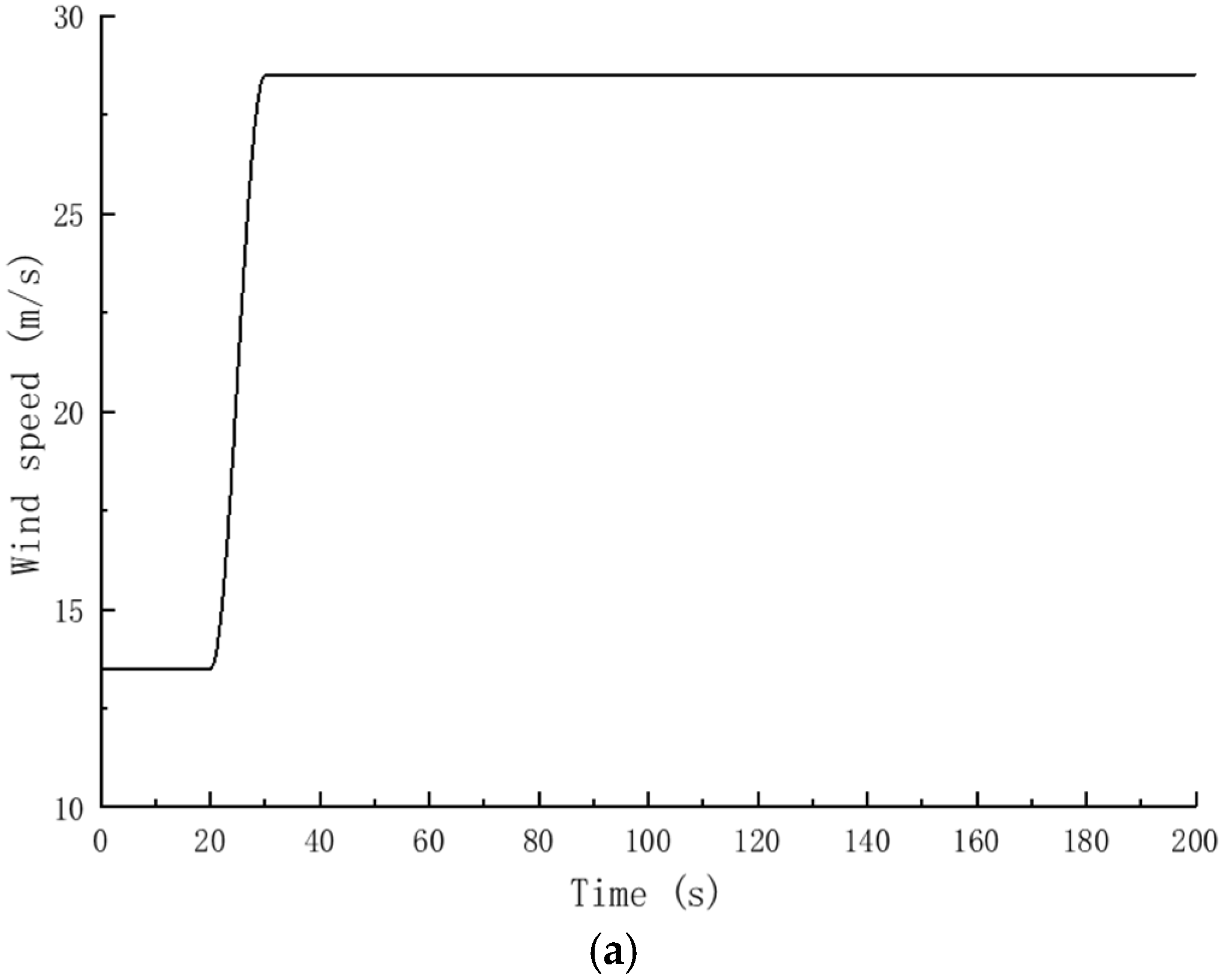
3.1. Wind Turbine and Extreme Gust Model

The wind turbine used in the simulation comes from one of wind turbine manufacturers in China, and the main parameters of the wind turbine are shown in Table 1. It is an upwind, three-blade commercial wind turbine with a rated power of 5 MW, the rotor diameter reaches 184 m, and the tower is a steel cone tower with a height of 110 m. The wind turbine dynamic response is simulated by GH-bladed.
According to IEC 61400-1 [6], the extreme coherent gust with direction change shall have a magnitude of the following.
V cg = 15 m / s
The wind speed can be defined by the following:
V ( z , t ) = V ( z ) for t 0 V ( z ) + 0.5 V c g 1 cos π t / T for 0 t T V ( z ) + V c g for t T
where T = 10 s corresponds to the rise time and wind speed V(z) is provided by the normal wind profile model.
The increase in wind speed during extreme coherent gusts is shown in Figure 4a, and the initial wind speed of the hub center is 13.5 m/s.
The increase in wind speed is assumed to occur simultaneously with a direction change θ from 0° up to θ cg , where magnitude θ cg is defined by the following.
θ cg ( V hub ) = 180 for V hub < 4 m / s 720 ( m / s ) V hub for 4 m / s < V hub < V r e f
The simultaneous direction change is then provided by the following:
θ ( t ) = 0 for t < 0 ± 0.5 θ c g 1 cos π t / T for 0 t T ± θ c g for t > T
where T = 10 s denotes rise time.
The direction change θ (t) function of time, for V hub = 13.5 m/s, is shown in Figure 4b.
Figure 4. Extreme coherent gust model. (a) Wind speed input data. (b) Wind direction input data.
Energies 15 04400 g004aEnergies 15 04400 g004b

3.2. Simulation Results Analysis

The key to using this protection strategy is the configuration of the look-up table, which involves the definition of the threshold value. If the threshold value is set to a small value, the system may identify some normal turbulent winds as extreme gusts, resulting in a reduction in power generation under normal working conditions. On the contrary, if the threshold value is set to a large value, protection may induce a reduced effect. When setting the threshold value, the principle adopted in this paper is to avoid losing power generation under normal working conditions. Throughout the simulation of the generator’s speed change rate of the wind turbine in the operating wind speed range, the extreme speed change rate value is taken as the threshold boundary, and the final threshold under different wind speeds is shown in Table 2.
Under the input gust file introduced in Section 3.1, the dynamic response of the wind turbine, with and without TCSP strategy, is simulated. The simulation duration is 200 s, the initial wind speed is 13.5 m/s, the gust variation amplitude is 15 m/s, the variation time is 10 s, and then it remains at 28.5 m/s. Figure 5 shows the comparison of the rotor speed of the wind turbine under two different conditions (with and without TCSP strategy). Before the gust occurs, the rotor speed is constant at a rated speed of 0.93 rad/s. After the gust occurs, the rotor speed quickly reaches 1.14 times the rated speed and exceeds the protection value (1.1 times the rated speed) in cases where the TSCP strategy is not applied. The shutdown protection strategy is then triggered. When the TSCP strategy is adopted, the maximum rotor speed is 1.021 rad/s. After a period of fluctuation, the rotor’s speed stabilizes near the rated speed.
Figure 6a,b show, respectively, a comparison of the pitch rate and the pitch angle of the wind turbine under two different conditions (with and without TCSP strategy). It can be observed from Figure 6a that when the TCSP strategy is applied, the pitch rate of the wind turbine is greatly improved and it reaches 1.5 times the maximum pitch rate under normal working conditions. The faster pitch rate causes the wind turbine to additionally increase the pitch angle at the same time, which limits the energy absorption of the wind turbine and avoids an overspeed of the generator. Figure 7 and Figure 8 show the comparison of the blade’s tip displacement and tower top My of the wind turbine under two different conditions (with and without TCSP strategy), respectively. When the TCSP strategy is adopted, the blade’s tip deformation is reduced by 19.9%. Simultaneously, the load on the top of the tower is reduced by 52.2%. The reduction in load at the top of the tower has a great significance on the cost reduction in the wind turbine. The above results show that the TCSP strategy does not only reduce the blade’s tip deformation under extreme gust conditions and protect the wind turbine’s safety, but it also reduces the load of the wind turbine and then its costs.

4. Conclusions

The blade length increase leads to a larger blade tip deformation. In addition, tower clearance often has difficulty in meeting the minimum safety distance requirements under extreme gust conditions. By analyzing the mathematical model of wind turbine, it was found that gust intensity is positively correlated with the generator’s speed change rate. Therefore, a gust identification method based on wind turbine monitoring data was proposed in this paper. By further analyzing the pitch control strategy of the wind turbine, it was found that the larger the blade angle, the smaller the gain of the controller. This leads to a slow blade pitch rate when wind speed increases sharply. Therefore, a novel TCSP strategy is proposed based on the extreme gust identification method. When extreme gusts are identified, some additional speed requirements are superimposed on the basis of the original pitch rate. Consequently, the system can act quickly to change under gust conditions and pitch remains at the normal rate under normal conditions. Considering a 5 MW wind turbine as an example, the dynamic response of the wind turbine is simulated with and without the TCSP strategy, and the results are as follows:
(a)
The generator speed of the wind turbine increases rapidly during extreme gusts, which can trigger overspeed protection and lead to an emergency shutdown. The coupling effect of the shutdown and gust makes the wind turbine produce strong dynamic responses.
(b)
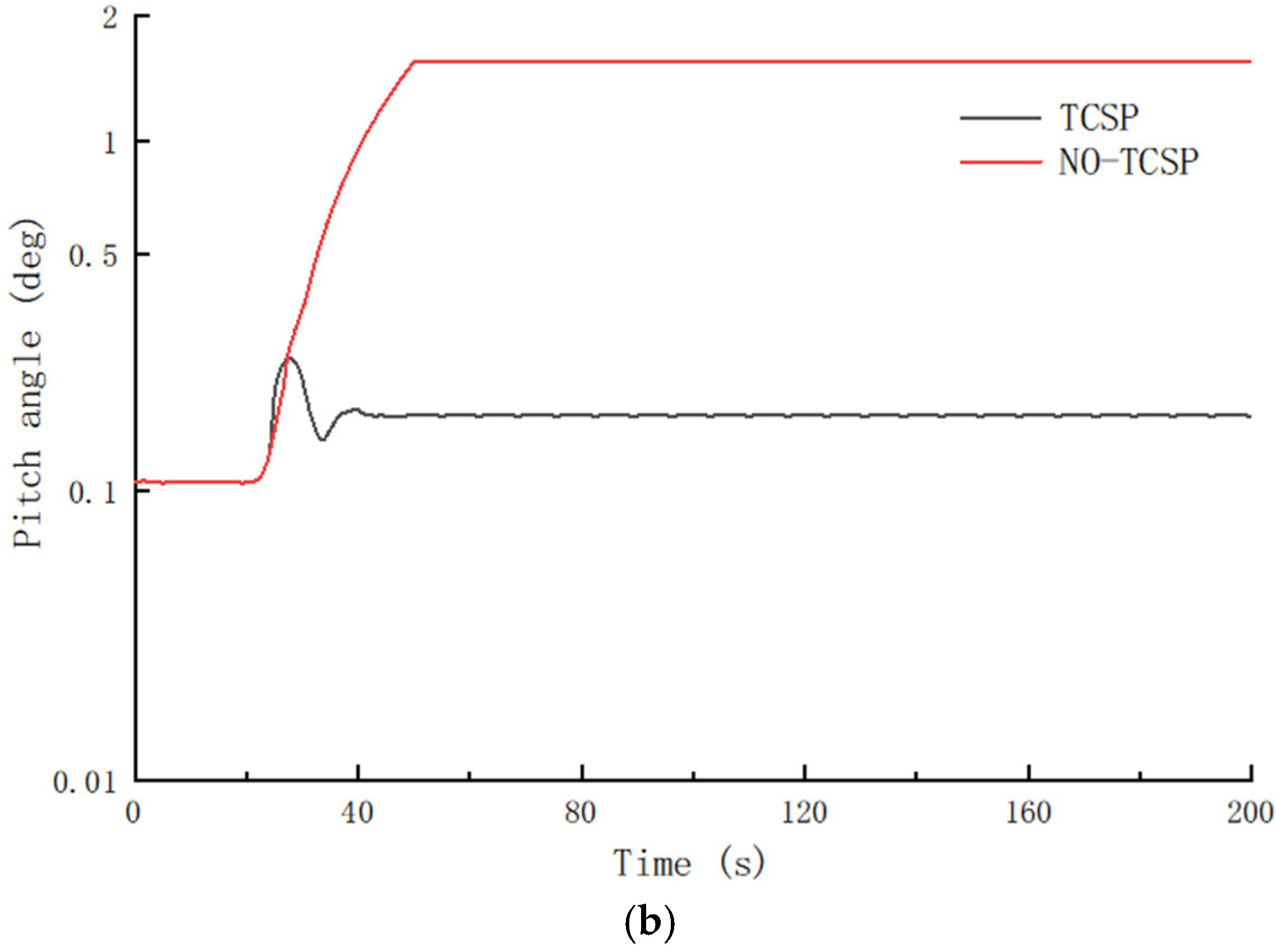
After adopting the TCSP strategy, the pitch rate under gust condition increased by 1.5 times; this causes the wind turbine to additionally increase the pitch angle at the same time and avoids an overspeed of the generator.
(c)
After adopting the TCSP strategy, blade tip deformation and the load on the top of the tower are reduced by 19.9% and 52.5%, respectively. This means that the TCSP strategy not only protects the wind turbine’s safety but also reduces costs.
Therefore, this paper provides a reference for clearance protection and load reduction of large-scale wind turbines under extreme gust conditions. Since the gust identification method proposed in this paper is based on wind turbine monitoring data, it can be applied to multiple applications without increasing costs.

Author Contributions

Conceptualization, S.L.; Data curation, Y.Z.; Formal analysis, Y.W.; Funding acquisition, X.C.; Methodology, B.X.; Software, S.B.; Writing—original draft, X.C.; Writing—review & editing, Y.W. All authors have read and agreed to the published version of the manuscript.

Funding

Supported by the Fundamental Research Funds for the Central Universities (Grant No. 2018B48614). The first group of 2011 plan of China’s Jiangsu province (Grant No. (2013) 56).

Conflicts of Interest

We declare that we do not have any commercial or associative interest that represents a conflict of interest in connection with the work submitted.

References

  1. Enevoldsen, P.; Xydis, G. Examining the trends of 35 years growth of key wind turbine components. Energy Sustain. Dev. 2019, 50, 18–26. [Google Scholar] [CrossRef]
  2. McKenna, R.; Pfenninger, S.; Heinrichs, H.; Schmidt, J.; Staffell, I.; Bauer, C.; Gruber, K.; Hahmann, A.N.; Jansen, M.; Klingler, M.; et al. High-resolution large-scale onshore wind energy assessments: A review of potential definitions, methodologies and future research needs. Renew. Energy 2022, 182, 659–684. [Google Scholar] [CrossRef]
  3. Cai, X.; Wang, Y.; Xu, B.; Feng, J. Performance and effect of load mitigation of a trailing-edge flap in a large-scale offshore wind turbine. J. Mar. Sci. Eng. 2020, 8, 72. [Google Scholar] [CrossRef] [Green Version]
  4. Hu, A.; Bu, A.; Vvs, B. Structural integrity analysis and damage assessment of a long composite wind turbine blade under extreme loading. Compos. Struct. 2020, 246, 112426. [Google Scholar]
  5. Zhu, X.; Chen, J.; Shen, X.; Du, Z. Impact of blade flexibility on wind turbine loads and pitch settings. J. Sol. Energy Eng. 2018, 141, 041002. [Google Scholar] [CrossRef]
  6. IEC 61400-1:2019; Systems—Part 1: Design Requirements. International Electrotechnical Commission: Geneva, Switzerland, 2019.
  7. Germanischer Lloyd. Guideline for the Certification of Wind Turbines; Germanischer Lloyd: Hamburg, Germany, 2010. [Google Scholar]
  8. Han, B.; Zhou, L. Research on individual pitch control below rated wind speed. IEEE Trans. Electr. Electron. Eng. 2017, 12, 38–44. [Google Scholar] [CrossRef]
  9. Bortolotti, P.; Bottasso, C.L.; Croce, A.; Sartori, L. Integration of multiple passive load mitigation technologies by automated design optimization—The case study of a medium-size onshore wind turbine. Wind Energy 2019, 22, 65–79. [Google Scholar] [CrossRef] [Green Version]
  10. Bernhammer, L.O.; Kuik, G.V.; Breuker, R. Fatigue and extreme load reduction of wind turbine components using smart rotors. J. Wind Eng. Ind. Aerodyn. 2016, 154, 84–95. [Google Scholar] [CrossRef]
  11. Lackner, M.A.; Kuik, G.V. The performance of wind turbine smart rotor control approaches during extreme loads. J. Sol. Energy Eng. 2010, 132, 937. [Google Scholar] [CrossRef]
  12. Zhang, M.M.; Tan, B.; Xu, J.Z. Smart load control on large-scale wind turbine blades due to extreme coherent gust with direction change. J. Renew. Sustain. Energy 2015, 7, 023110. [Google Scholar] [CrossRef]
  13. Meng, F.; Wenske, J.; Gambier, A. Wind turbine loads reduction using feedforward feedback collective pitch control based on the estimated effective wind speed. In Proceedings of the American Control Conference, Boston, MA, USA, 6–8 July 2016. [Google Scholar]
  14. Zhuang, Z.; Liu, X.; Chen, X. Estimation method of turbulent wind speed based on lidar pulse characteristics. Infrared Laser Eng. 2018, 47, 1106001. [Google Scholar] [CrossRef]
  15. Cortina, G.; Calaf, M. Turbulence upstream of wind turbines: A large-eddy simulation approach to investigate the use of wind lidars. Renew. Energy 2017, 105, 354–365. [Google Scholar] [CrossRef]
  16. Kumer, V.M.; Reuder, J.; Dorninger, M.; Zauner, R.; Grubišić, V. Turbulent kinetic energy estimates from profiling wind lidar measurements and their potential for wind energy applications. Renew. Energy 2016, 99, 898–910. [Google Scholar] [CrossRef] [Green Version]
  17. Pace, A.; Johnson, K.; Wright, A. Preventing wind turbine overspeed in highly turbulent wind events using disturbance accommodating control and light detection and ranging. Wind Energy 2015, 18, 351–368. [Google Scholar] [CrossRef]
  18. Haizmann, F.; Schlipf, D.; Cheng, P.W. Lidar-assisted extreme load reduction by multi-variable protective derating. J. Phys. Conf. Ser. 2018, 1037, 032025. [Google Scholar] [CrossRef]
  19. Rodrigo, J.S.; Gancarski, P.; Arroyo, R.C.; Moriarty, P.; Chuchfield, M.; Naughton, J.W.; Hansen, K.S.; Machefaux, E.; Koblitz, T.; Maguire, E.; et al. Iea-task 31 wakebench: Towards a protocol for wind farm flow model evaluation. Part 1: Flow-over-terrain models. J. Phys. Conf. Ser. 2014, 524, 012105. [Google Scholar] [CrossRef] [Green Version]
  20. Dickler, S.; Wiens, M.; Thonnissen, F.; Jassmann, U.; Abel, D. Requirements on super-short-term wind speed predictions for model predictive wind turbine control. In Proceedings of the 2019 18th European Control Conference (ECC), Naples, Italy, 25–28 June 2019. [Google Scholar]
  21. Lio, A.; Meng, F. Effective wind speed estimation for wind turbines in down-regulation. J. Phys. Conf. Ser. 2020, 1452, 012008. [Google Scholar] [CrossRef] [Green Version]
  22. Soltani, M.N.; Knudsen, T.; Svenstrup, M.; Wisniewski, R. Estimation of rotor effective wind speed: A comparison. IEEE Trans. Control Syst. Technol. 2013, 21, 1155–1167. [Google Scholar] [CrossRef]
  23. Gocmen, T.; Giebel, G. Estimation of turbulence intensity using rotor effective wind speed in lillgrund and horns rev-i offshore wind farms. Renew. Energy 2016, 99, 524–532. [Google Scholar] [CrossRef] [Green Version]
  24. Kanev, S.; Engelen, T.V. Wind turbine extreme gust control. Wind Energy 2010, 13, 18–35. [Google Scholar] [CrossRef]
  25. Wiens, M.; Meyer, T.; Wenske, J. Exploiting bend-twist coupling in wind turbine control for load reduction. IFAC-PapersOnLine 2020, 53, 12139–12144. [Google Scholar] [CrossRef]
  26. Kumar, D.; Chatterjee, K. A review of conventional and advanced MPPT algorithms for wind energy systems. Renew. Sustain. Energy Rev. 2016, 55, 957–970. [Google Scholar] [CrossRef]
  27. Elsisi, M.; Tran, M.Q.; Mahmoud, K.; Lehtonen, M.; Darwish, M. Robust design of ANFIS based blade pitch controller for wind energy conversion systems against wind speed fluctuations. IEEE Access 2021, 9, 37894–37904. [Google Scholar] [CrossRef]
  28. Bossanyi, E.A. The design of closed loop controllers for wind turbines. Wind Energy 2000, 3, 149–163. [Google Scholar] [CrossRef]
Figure 1. Mathematical model of wind turbine.
Energies 15 04400 g001
Figure 2. Wind turbine main controller and filter circuit.
Energies 15 04400 g002
Figure 3. Tower clearance safety protection strategy. (a) Revised pitch controller. (b) Flow of the strategy.
Energies 15 04400 g003aEnergies 15 04400 g003b
Figure 5. Rotor speed comparison.
Energies 15 04400 g005
Figure 6. Pitch information of the wind turbine during simulation. (a) Pitch rate. (b) Pitch angle.
Energies 15 04400 g006aEnergies 15 04400 g006b
Figure 7. Tower top My comparison.
Energies 15 04400 g007
Figure 8. Blade tip displacement comparison.
Energies 15 04400 g008
Table 1. Wind turbine information and simulation parameters.
Wind Turbine TypeCT 5.0-184
Rotor diameter (m)184
Rated power (MW)5
Design wind zoneIEC IIIB
Cut-in wind speed (m/s)2.5
Cut-out wind speed (m/s)20
Rotor speed (r/min)5~9.8
Blade tip Pre-bend (m)3.95
Rotor cone angle (deg)−5
Rotor tilt angle (deg)7
Tower height (m)110
Table 2. Look-up table of the threshold value.
Pitch Angle (rad)00.0872660.2617990.3490660.6108650.610865
Threshold101545606060
Publisher’s Note: MDPI stays neutral with regard to jurisdictional claims in published maps and institutional affiliations.

