Abstract
The shale oil horizontal wells in the Songliao Basin are affected by a lack of mature theories, technologies and experiences in the direction of wellbore stability. Wellbore collapse may occur, and in severe cases, the wellbore may be scrapped, resulting in huge economic losses. Therefore, aiming at addressing the above problems, rock mechanics experiments were carried out. Based on the theories of elasticity and rock mechanics, this paper considers not only the influence of the bedding plane, but also the influence of hydration on the strength weakening of the shale body and the bedding plane. The analysis shows that no matter under which in situ stress mechanism, the wellbore in the vertical well section is the most stable, and when the inclination angle is approximately 45°, the wellbore is most likely to be unstable. Changes in water content do not affect the most stable or unstable regions. Under the same conditions, the equivalent density of collapse pressure increases with the increase in water content. In addition, field examples are also analyzed to verify the accuracy of this model, which can provide a theoretical and technical basis for the safe construction of continental shale oil horizontal wells.
1. Introduction
With the increasing importance of unconventional oil and gas resources in the global energy structure, shale oil has become a hot area of energy exploration and development [1,2,3]. The development of continental shale oil in China is still in its infancy. The shale oil horizontal wells in Block G in the Songliao Basin are affected by a lack of mature theories, technologies and experiences in the direction of wellbore stability [4,5,6,7,8]. The continental shale oil in the northern Songliao Basin has huge potential resources and has become an important strategic replacement resource in Daqing. In 2020, the daily oil and gas equivalent of Well A2 reached more than 39 tons, showing a promising prospect for exploration and development [9,10,11,12,13]. The Q1 and Q2 groups in block G develop large sections of shale with extremely well-developed bedding. The mineral components are mainly dolomite, calcite and quartz, which are hard and brittle shale, and the average content of clay minerals is over 40%. Therefore, during the drilling process, the shale is prone to hydration and expansion. Downhole accidents such as wellbore collapse and block drop may occur, and in severe cases, the wellbore may be scrapped, resulting in huge economic losses. The wellbore instability problem of shale oil horizontal wells is one of the technical bottlenecks restricting the safe and efficient development of shale oil [14,15,16,17].
Experts and scholars at home and abroad have carried out a large number of experiments and theoretical research on the direction of wellbore stability, and have achieved rich results. Jaeger et al. [18] originally proposed the strength failure criterion of rock weak plane. On this basis, Liu et al. [19,20] established a collapse pressure prediction model considering the influence of weak plane based on the theory of continuum mechanics and stress coordinate system transformation, and analyzed the effects of weak plane and occurrence on wellbore stability. Shuai et al. [21,22] combined the wellbore stress model and the weak plane failure criterion under the condition of deviated wells, established the formation collapse pressure model of highly deviated wells, and analyzed the factors affecting wellbore stability. The above studies only consider the effect of weak plane on wellbore stability, and do not consider the influence of hydration on wellbore stability. Aadnoy [23] established a collapse pressure model that considered both bedding occurrence and shale strength weakening, and analyzed the factors affecting the collapse pressure distribution. Combined with the weak plane strength criterion, Ma et al. [24,25,26,27,28,29] established an analysis model for the wellbore stability of layered shale horizontal wells, and analyzed the effects of bedding occurrence and water content on the collapse pressure of horizontal wells. However, the current research on shale wellbore stability in China mainly focuses on the marine shale of Longmaxi Formation in Sichuan, and the wellbore instability of continental shale in the north of Songliao Basin has not been studied. At present, for the problem of wellbore stability of continental shale in the north of Songliao Basin, only the corresponding relationship between logging parameters and wellbore rock mechanical properties has been preliminarily established. In the field, the drilling fluid density is roughly adjusted according to the occurrence of wellbore collapse [30,31]. At present, how to establish the wellbore stability model of layered continental shale under different working conditions is the bottleneck restricting further research on the wellbore stability of shale drilling in this block.
Therefore, in view of the above problems, this paper carried out rock mechanics experimental research, based on the obtained rock mechanics data, in-depth analysis of the wellbore instability mechanism and main controlling factors of the Gulong shale layer, and a clear algorithm for obtaining the formation collapse pressure. Therefore, aiming at addressing the above problems, rock mechanics experiments were carried out, including triaxial compressive strength experiments and tensile strength experiments. On the basis of rock mechanics data, the mechanism of wellbore instability and its influencing factors in Gulong shale are deeply analyzed, and the algorithm for calculating formation collapse pressure is determined. Based on the theories of elasticity and rock mechanics, this paper considers not only the influence of the bedding plane, but also the influence of hydration on the strength weakening of rock body and the bedding plane. A prediction model for the wellbore collapse pressure of a horizontal well in layered continental shale oil is established, the mechanism of wellbore instability of a horizontal well in layered shale is studied, and the influence laws of different in situ stress conditions, wellbore trajectory, water content, bedding plane occurrence and other factors on collapse pressure are analyzed. In addition, field examples are also analyzed to verify the accuracy of this model, which can provide a theoretical and technical basis for the safe construction of continental shale oil horizontal wells [32,33,34].
2. Rock Mechanics Experiments of Layered Shale
2.1. Experimental Core Preparation
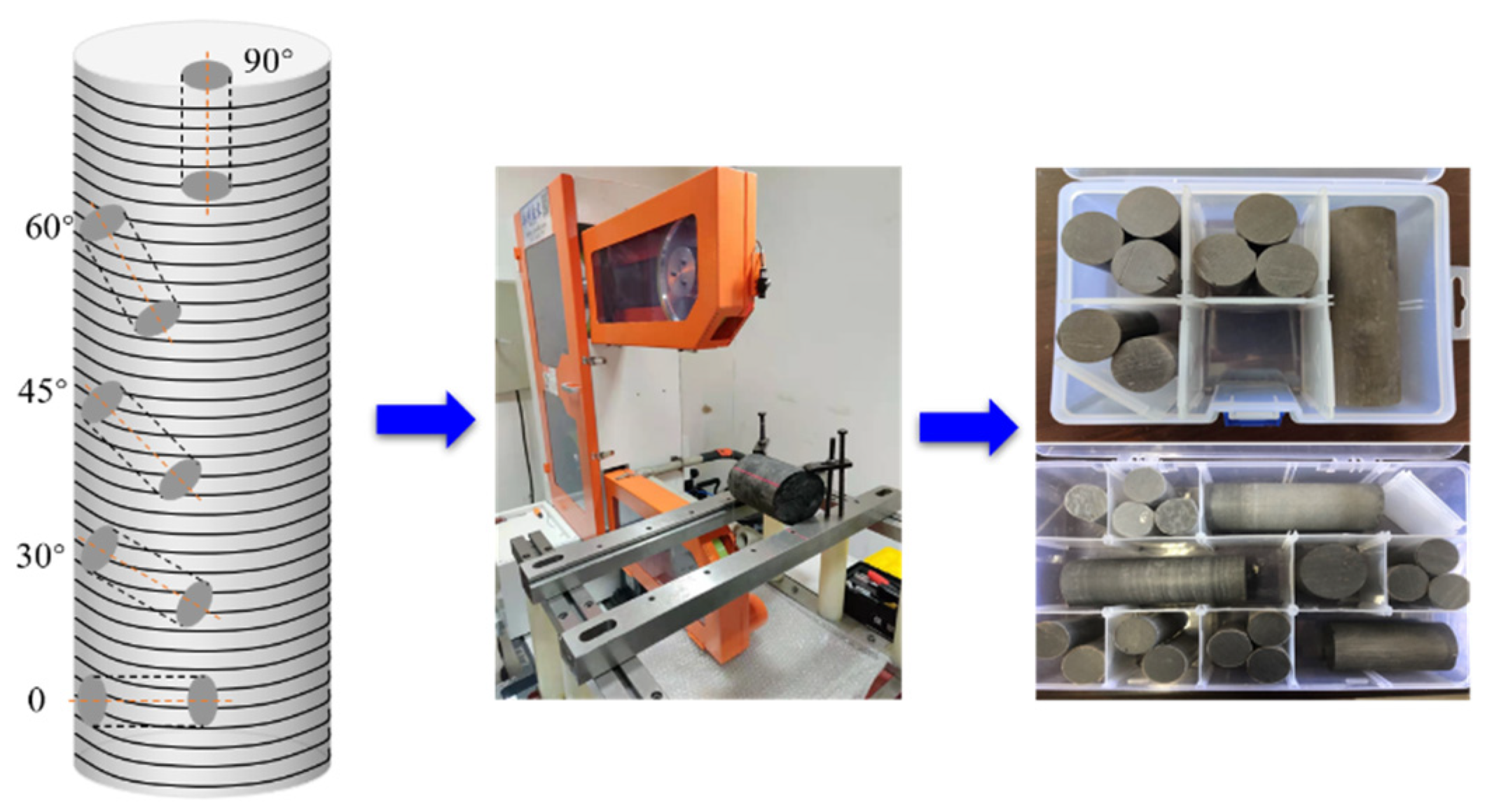
Since the shale is prone to hydration expansion when encountering water, it cannot be cut and cored used in conventional processing methods, so the full-size core is processed by using the NC wire cutting method. According to the coring method in Figure 1 [35], the 0, 30°, 45°, 60°, 90° direction cores are processed, respectively, and both ends of the sample are cut fat and polished to make the length diameter ratio of the shale sample approximately 2.
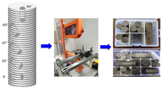
Figure 1.
Preparation of standard rock samples by NC wire cutting.
2.2. Triaxial Compressive Strength Test
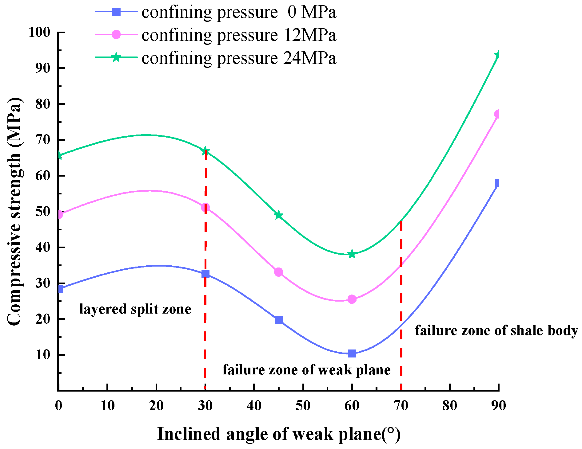
According to the regulations, the standard specimen is a cylinder with a diameter of 2.5 cm and a height of 5.0 cm, and the allowable variation range is 4.8~5.2 cm. During axial loading, the strain rate should be controlled within 1 × 10⁻⁵ mm/s. When the pressure is loaded in two directions, parallel to the bedding and perpendicular to the bedding, the fracture patterns of the rock are different. When the pressure is loaded parallel to the bedding direction, the shale will open many times along the bedding fractures, forming multiple groups of fragments along the bedding plane direction. When the pressure is loaded perpendicular to the bedding direction, shear cracks are first generated. When the shear cracks are connected with the micro-cracks along the bedding, large volume fractures will be formed. The practical experience of on-site horizontal well drilling shows that the wellbore collapse is the most serious in the build-up section with an inclination angle of 30°~75°. Therefore, the angle between the direction of loading pressure and bedding (approximately equal to the deviation angle in actual drilling) is divided into three areas through laboratory experimental research. As shown in Figure 2, 0°~30° is divided into layered split zone. 30°~75° is divided into failure zone of weak plane and 75°~90° is divided into failure zone of the shale body.
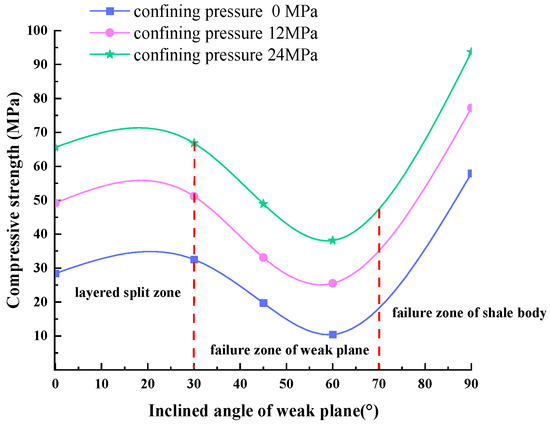
Figure 2.
The relationship between the triaxial compressive strength and the angle between the loading pressure direction and the bedding direction.
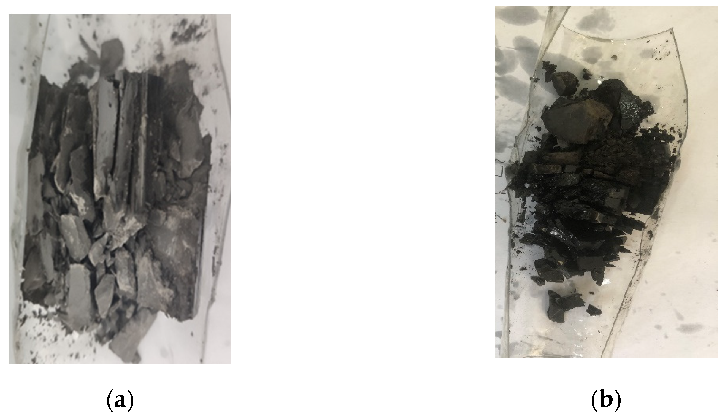
According to the fracture shape of shale in Figure 3, when the pressure is loaded along the parallel bedding direction, the bedding fractures will be opened many times, resulting in tensile failure. Therefore, when the shale is loaded with pressure in the horizontal direction, it is hard and brittle, forming multiple groups of fragments. When the shale is loaded with pressure perpendicular to the bedding direction, it needs to overcome the shear strength of the shale body and shows a certain plastic deformation. It is caused by the closure and expansion of micro-fractures under the action of loading pressure, which needs to overcome the shear strength of the shale body. The following three conclusions are drawn: (1) When the angle between the loading pressure direction and the bedding is 0°~30°, the splitting failure mainly occurs along the bedding plane. (2) When the angle between the loading pressure direction and the bedding is 30°~75°, the shear slip mainly occurs along the bedding plane. When the angle is 50°~60°, the compressive strength of the shale body is the minimum. (3) When the angle between the loading pressure direction and the bedding is 75°~90°, the shear failure of the shale body mainly occurs, and the compressive strength of the shale body is the maximum at this time.
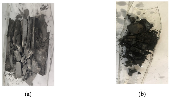
Figure 3.
Photos of shale destroyed in triaxial compression experiment: (a) photo of shale being destroyed when loaded parallel to the bedding direction; (b) photo of shale being destroyed when loaded perpendicular to the bedding direction.
2.3. Tensile Strength Test of Shale
The tensile strength test is carried out using an indirect test method, the Brazilian split tensile test method. The rock sample is processed into a cylindrical specimen with a diameter of approximately 38 mm and a length of approximately 19 mm, basically maintaining a diameter to thickness ratio of 2:1. The shale is more prone to tensile failure when loaded parallel to the bedding direction than when loaded perpendicular to the bedding direction. When the included angle with the bedding direction is 45°, the shale undergoes shear slip, and the shear strength of the bedding plane is much lower than the tensile strength of the shale body. Therefore, the continental shale in the Songliao Basin has well-developed bedding and low shear strength, which leads to the easy opening of fractures along the bedding direction, which is an important factor affecting the stability of the wellbore.
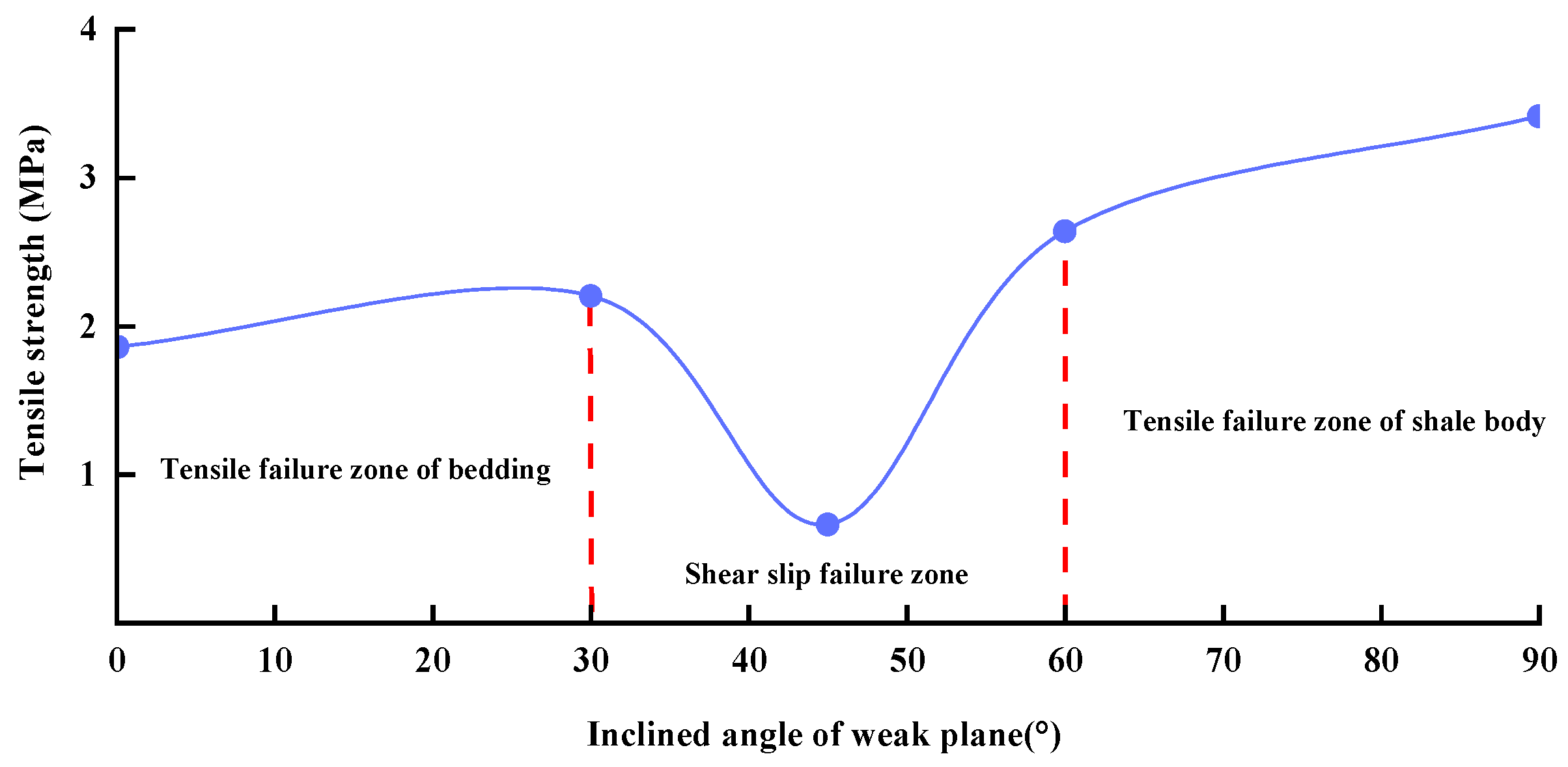
In the same way as the triaxial compressive strength test, according to the collapse and fracture characteristics of the wellbore, and according to the angle between the loading pressure direction and the bedding direction (well inclination angle), the tensile strength can be divided into three areas: tensile failure zone of bedding, shear slip failure zone and tensile failure zone of the shale body, as shown in Figure 4.
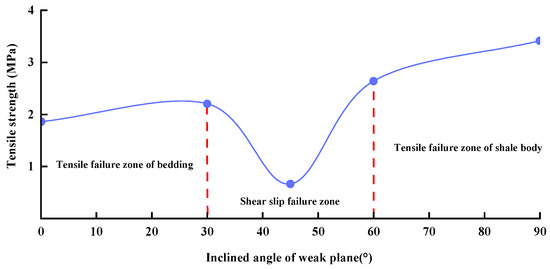
Figure 4.
The relationship between the tensile strength and the angle between the loading pressure direction and the bedding direction.
When the inclination angle is 0°~30°, the formation fracture belongs to the tensile failure of the bedding plane, and the collapse belongs to the shear failure of the shale body. The fracture pressure and collapse pressure are both low, and the drilling fluid density should not be too high. When the well inclination is 30°~60°, the shear strength of shale is much lower than the tensile strength, and the drilling fluid density window is the narrowest, so precise pressure control should be ensured. When the inclination angle is 60°~90°, the formation fracture belongs to the tensile failure of the shale body, and the collapse belongs to the bedding splitting or shear failure. Both the collapse pressure and the fracture pressure increase, and the drilling fluid density should be appropriately increased. The following three conclusions are drawn: (1) When the angle between the loading pressure direction and the bedding direction is 0°~30°, tensile failure mainly occurs along the bedding plane. (2) When the angle between the loading pressure direction and the bedding direction is 30°~60°, shear slip failure mainly occurs along the bedding plane. When the angle between the loading pressure direction and the bedding direction is 45°, the tensile strength is the minimum. (3) When the angle between the loading pressure direction and the bedding direction is 60°~90°, the tensile failure of the shale body mainly occurs.
3. Prediction Model of the Collapse Pressure of a Horizontal Well in Layered Shale
3.1. Borehole Stress Considering Hydration Strain
The stress–strain (hydration strain) equilibrium equation of rock around the well under hydration is [36]:
where and are the radial stress and circumferential stress under the cylindrical coordinate system of the wellbore, respectively, Pa; is the radius, m.
The radial stress on the wellbore is equal to the pressure of the drilling fluid column in the well, that is, the inner boundary condition is . The radial stress at infinity from the wellbore is equal to the in-situ stress, that is, the outer boundary condition is .
Substitute the internal and external boundary conditions into the stress-strain equilibrium equation, and the general solution of the stress-strain equilibrium equation (that is, the radial displacement ) is finally obtained as follows:
where and are the principal stresses in the X-axis and Y-axis directions under the borehole rectangular coordinate system, Pa; u is radial displacement, m; is the effective liquid column pressure in the well, Pa; is the elastic modulus when the formation water content is , Pa; is the Poisson’s ratio when the formation water content is ; R is the borehole radius, m.
According to the plane strain geometric equation of the axisymmetric wellbore, the radial and circumferential hydration strains generated by hydration can be obtained:
where is the radial strain; is the tangential εθθ strain.
The vertical hydration strain is:
where: ; ; is the vertical
hydration strain; is the increment of water content; ; is the original formation water content.
Finally, the hydration stress of the layered shale in the plane two-dimensional spatial cylindrical coordinate system is obtained as follows:
where , and are respectively the radial stress, circumferential stress and axial stress in the cylindrical coordinate system of the wellbore when the bedding plane is considered, Pa; m is the anisotropic ratio.
3.2. Wellbore Circumferential Stress Produced by In Situ Stress
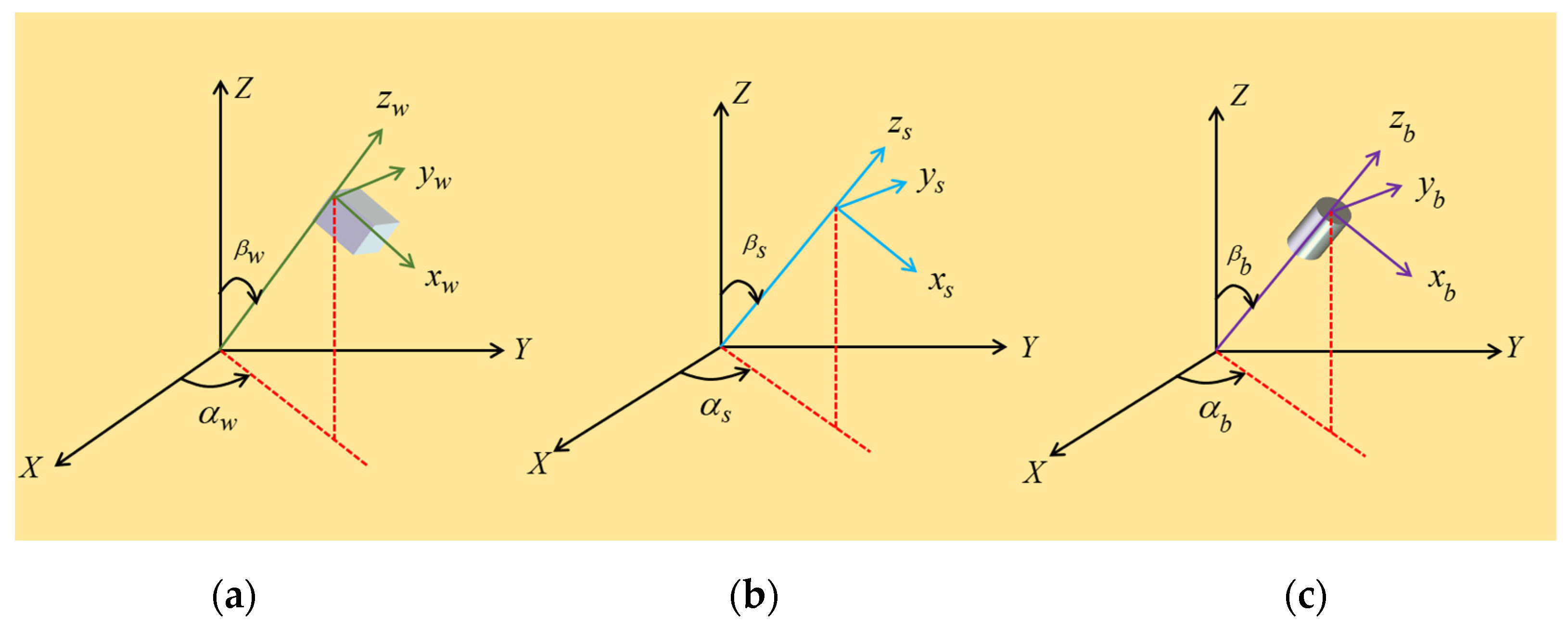
As shown in Figure 5, the principal stress and shear stress in the cylindrical coordinate system around the borehole are obtained by coordinate transformation as:
where is the axial stress under the cylindrical coordinate system of the wellbore, Pa; , and are the tangential stresses in three planes under the cylindrical coordinate system of the wellbore, Pa; is the azimuth along the wellbore circumference, .
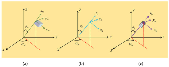
Figure 5.
Reference coordinate system: (a) stratigraphic rectangular coordinate system; (b) in situ stress rectangular coordinate system; (c) borehole rectangular coordinate system.
3.3. Total Effective Stress of Wellbore
The total effective stress of the wellbore consists of two parts, one is the hydration stress generated by the hydration strain of shale, and the other is the stress generated by the in situ stress. The calculation formula is as follows:
When , the total effective stress on the shaft wall can be obtained:
where , , , , and are the total effective stress components of the wellbore after considering the hydration stress, Pa; is the effective stress coefficient; is the formation pore pressure, Pa.
According to formula (8), is one of the principal stresses, that is, . The calculation formula of the other two principal stresses is:
Then, the maximum and minimum principal stresses are:
where , and are the principal stress on the wellbore, Pa; and are the maximum and minimum principal stresses, respectively, Pa.
The maximum principal stress and the minimum principal stress on the wellbore of a shale oil horizontal well can be obtained through the above model, and the collapse pressure can be obtained by combining the Mohr–Coulomb weak plane strength criterion [37].
3.4. Determination of Collapse Pressure
The layered continental shale formation has a set of approximately parallel bedding planes, and the strength of the bedding plane is lower than that of the shale body, which is also called the weak plane. Jaeger proposed the single weak plane strength theory, which is a generalization of the Mohr–Coulomb failure criterion, which can describe the shear failure of a rock mass with one or a group of parallel weak planes, as shown in Figure 6. In this paper, the strength theory of single weak surface is used as the criterion of wellbore instability.
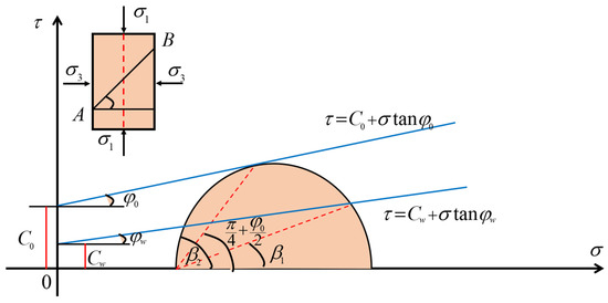
Figure 6.
Schematic diagram of single weak plane strength theory [38].
The lower limit and upper limit of when the weak plane is broken are:
From the Mohr stress circle, it can be seen that when a, the failure of the weak surface causes the instability of the wellbore. When a or a, the weak surface is stable, at this time the rock body is damaged and the borehole wall is unstable. The basis for determining the failure of rock body is as follows:
From the Mohr stress circle, it can be seen that under the condition , the failure of the weak plane causes the instability of the wellbore. Under the condition or , the weak plane is stable, and the shale body failure causes the instability of the wellbore. The basis for determining the failure of shale body is as follows:
where is the angle between the normal of the weak plane and the maximum principal stress, ; is the cohesion of weak plane, MPa; ; is the friction angle of weak plane, ; is the bedding plane inclination, ; is the dip angle of bedding plane, .
Based on the mechanical parameter test data of shale core under different water content, the variation law of shale mechanical characteristic parameters with water content is obtained:
where is the initial elastic modulus, Pa; is the initial Poisson’s ratio; is the initial cohesion, Pa; is the original internal friction angle, ; is the Poisson’s ratio when the formation water content is ; is the cohesion when the formation water content is , Pa; is the internal friction angle when the formation water content is , .
3.5. Solution of Collapse Pressure Model
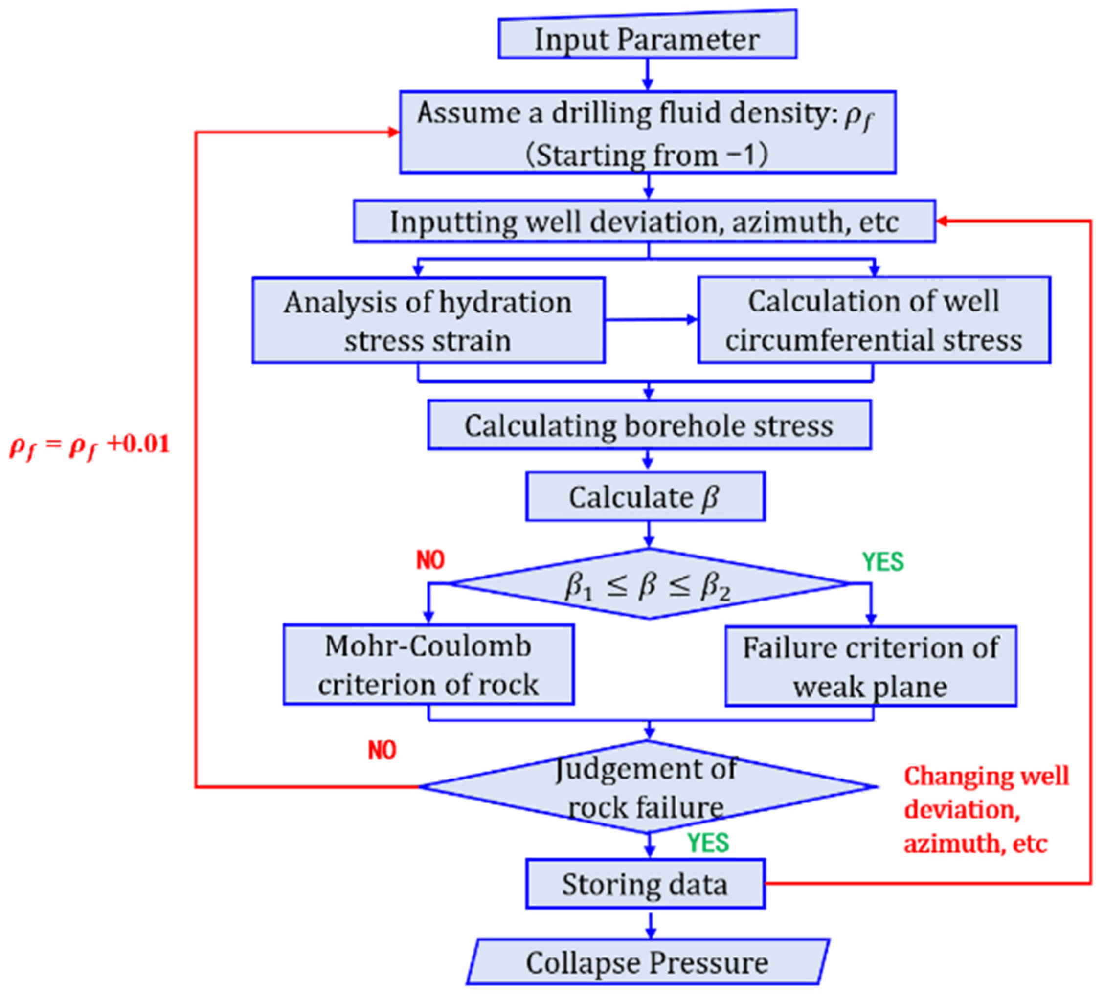
In this paper, Matlab is used to compile a program to calculate the collapse pressure by the iterative method, which is used to predict the collapse pressure of shale oil horizontal wells under the condition of mechanical–chemical coupling considering the influence of the bedding plane. The solution flow of the calculation program is shown in Figure 7.

Figure 7.
Solution flow of collapse pressure.
4. Analysis of Influencing Factors of Wellbore Instability in Layered Shale
For the layered shale in the Songliao Basin, the collapse pressure is closely related to the in situ stress, wellbore trajectory, rock mechanical parameters, hydration characteristics and other factors. In order to analyze the influencing factors of wellbore instability of continental shale in Songliao Basin, based on the measured data, the effects of different in situ stress conditions, different water content and different number of structural planes on the collapse pressure are calculated, respectively. The basic parameters used are shown in Table 1:

Table 1.
Basic stratigraphic parameters of continental shale in Songliao Basin.
4.1. Influence of In Situ Stress Conditions on Collapse Pressure
Under the condition of keeping the three main in situ stresses unchanged, three different geostress conditions ( and ) are used to analyze the variation of equivalent density of collapse pressure with well deviation and azimuth.
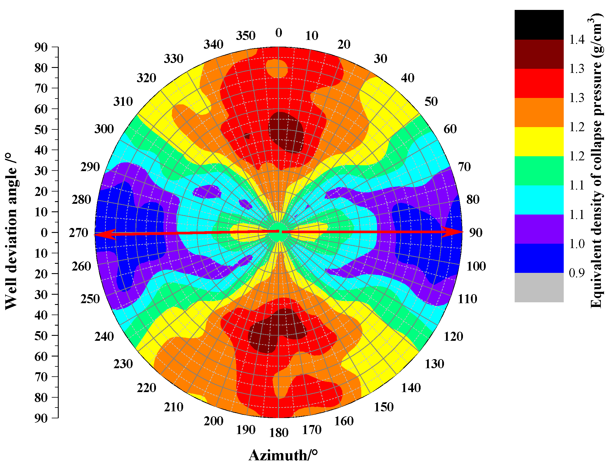
Figure 8 shows the variation law of collapse pressure equivalent density with well inclination and azimuth under normal fault condition (). Under the conditions of this study, the collapse density can reach up to 1.41 g/cm3 and the lowest is 0.83 g/cm3. When the azimuth angle is constant, the collapse pressure shows an increasing trend with the increase in the inclination angle. The azimuth angles of 0° and 180° are the safest for drilling.
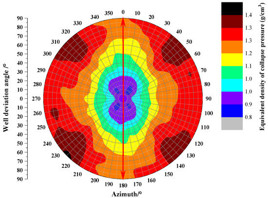
Figure 8.
Under normal fault condition ().
Figure 9 shows the variation law of collapse pressure equivalent density with well inclination and azimuth under strike-slip fault condition (). The maximum collapse density can reach 1.38 g/cm3 and the minimum is 0.91 g/cm3 under the condition of this study. The collapse density values at azimuth angles of 50°, 130°, 230° and 330° corresponding to well deviation angles of 0~90° are low, so it is relatively safe to drill along this direction.
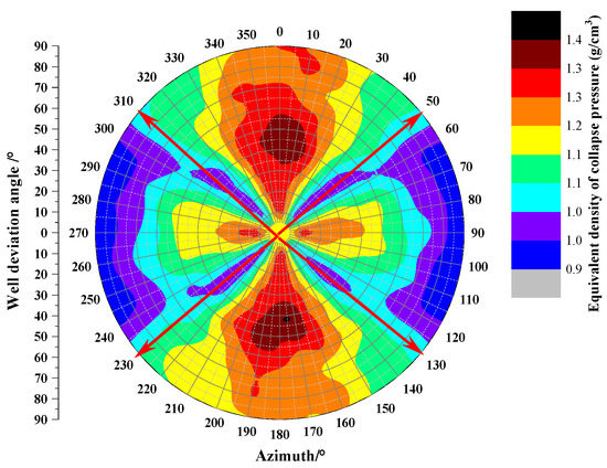
Figure 9.
Under strike-slip fault condition ().
Figure 10 shows the variation law of collapse pressure equivalent density with well inclination and azimuth under reverse fault condition (). The maximum collapse density can reach 1.40 g/cm3 and the minimum is 0.95 g/cm3. The collapse density values at azimuth angles of 50°~130° and 230°~310° corresponding to well deviation angles of 0~90° are low, and drilling along this direction is the safest under the condition of this study.
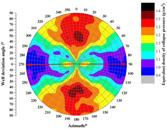
Figure 10.
Under reverse fault condition ().
The analysis shows that no matter under which in situ stress mechanism, the wellbore in the vertical well section is the most stable, and when the inclination angle is approximately 45°, the wellbore is most likely to be unstable.
4.2. Influence of Water Content on Collapse Pressure
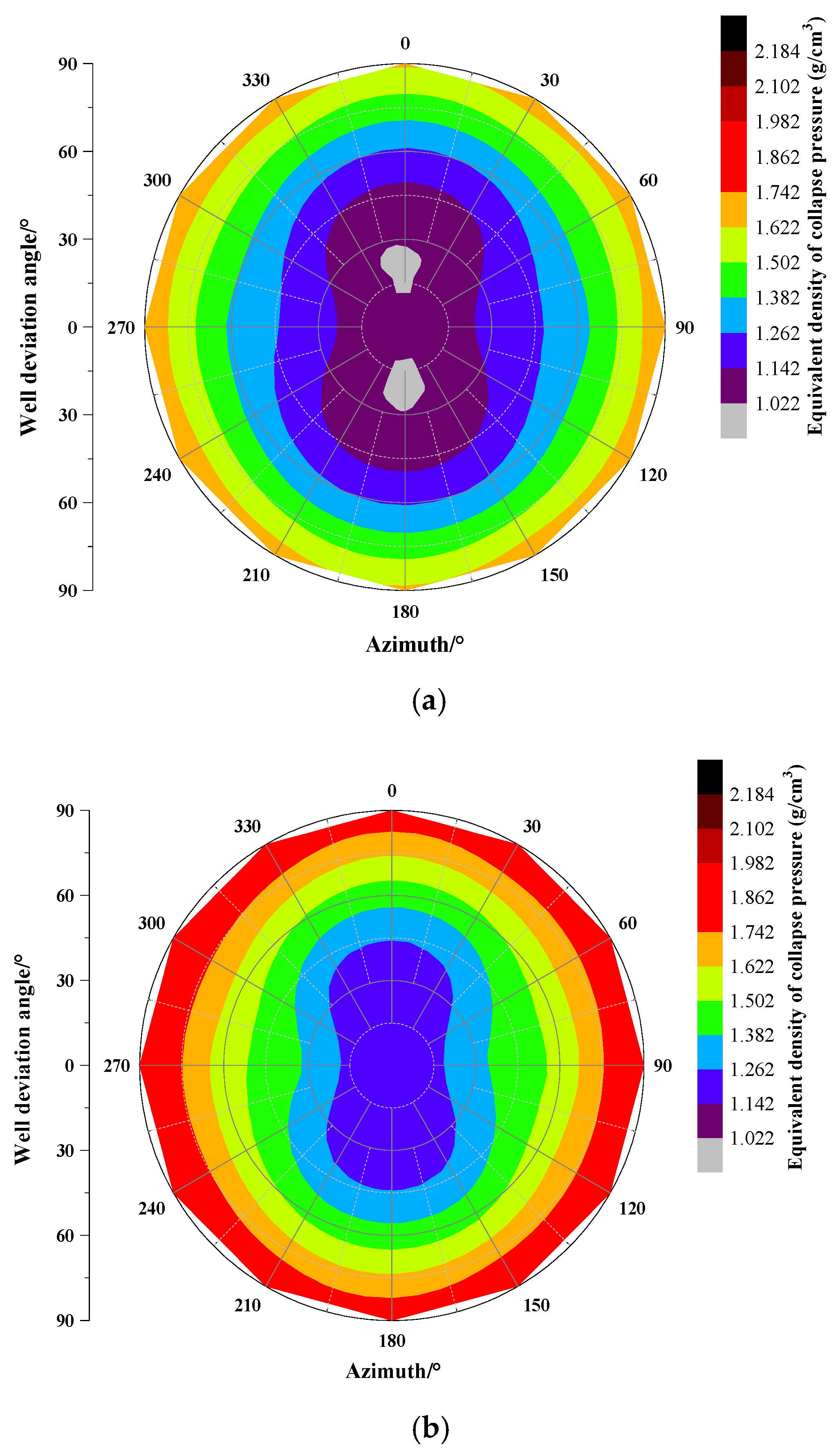
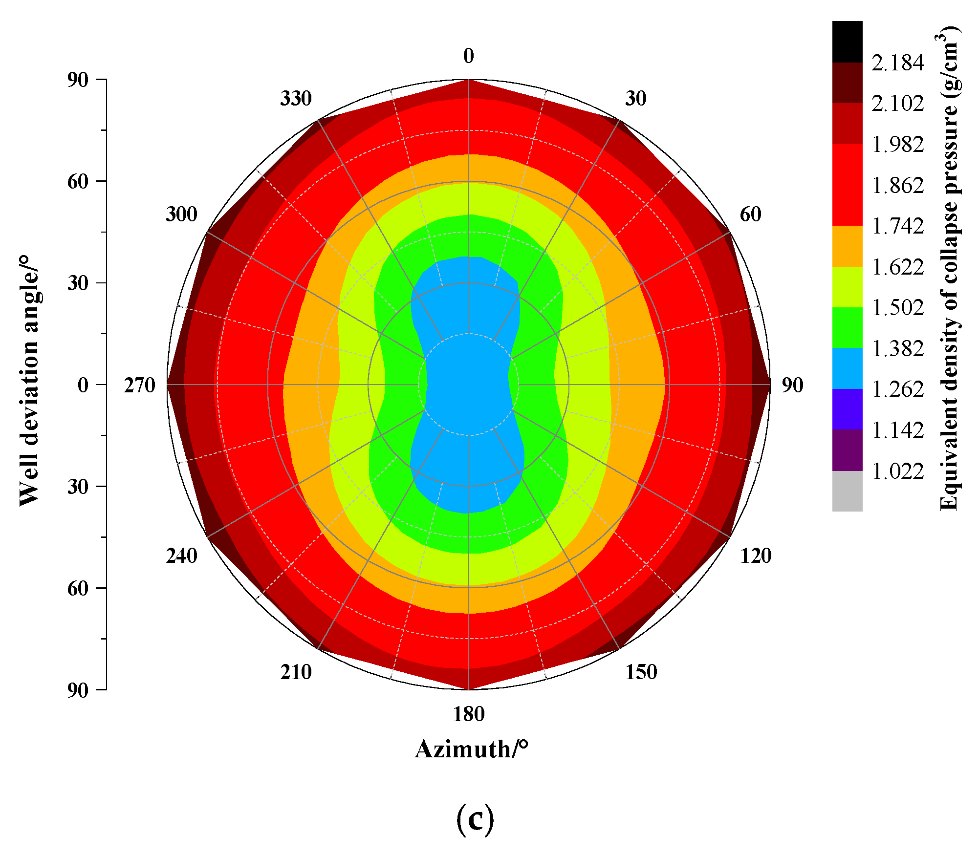
The variation law of collapse pressure equivalent density with well inclination and azimuth under different water content is analyzed, and the results are shown in Figure 11. It can be seen from the analysis that the most stable region and the easily unstable region of the wellbore hardly change with the increase in water content. The reason may be that under the given calculation conditions, the weakening effect of increasing water content on rock mechanical parameters is greater than the change of hydration expansion stress, resulting in the most stable region and the most unstable region of the wellbore hardly changing with the change of water content. The equivalent density of collapse pressure corresponding to different well inclinations and azimuths increases with the increase in water content. The reason may be that the weakening degree of hydration stress and hydration on rock mechanical parameters increases with the increase in water content. Finally, the equivalent density of collapse pressure increases with the increase in water content.
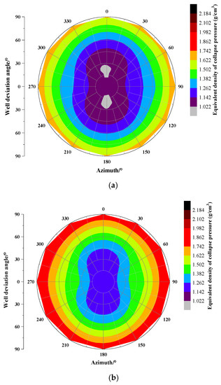

Figure 11.
Collapse pressure distribution under different water content: (a) water content is 5%; (b) water content is 10%; (c) water content is 15%.
Therefore, when the water-based drilling fluid is used to drill into the layered shale formation, the hydration strain has a relatively large influence on the collapse pressure. When designing the density of the drilling fluid, not only the influence of hydration on the rock mechanical property parameters, but also the rock mechanical property parameters should be considered. The effect of hydration strain on collapse pressure needs to be considered at the same time.
4.3. Influence of the Number of Structural Planes on Collapse Pressure
The structural plane refers to the differentiation plane and discontinuity plane of various substances in the rock, such as fault, bedding, joint and schistosity. Five parameters such as occurrence, shape, filling characteristics, ductility and density can be used to quantitatively characterize the size, direction, type and development degree of structural planes. The numerical simulation mainly simulates the influence of the number of structural planes on the collapse pressure distribution when they are 0, 1 and 3, respectively.
As shown in Figure 12, as long as the number of structural planes is greater than or equal to 1, the equivalent density of the overall collapse pressure will increase. When there is no structural plane, the variation range of collapse density is 0.86~1.38 g/cm3; When there are 1~3 structural planes, the variation range of collapse density is 0.93~1.73 g/cm3, and the increase range is 0.17~0.35 g/cm3. It can be seen that the existence of a structural plane will greatly increase the risk of wellbore collapse.
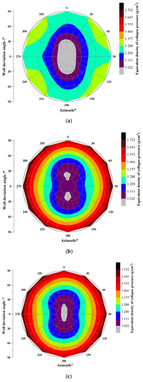
Figure 12.
Collapse pressure distribution under different number of structural planes: (a) no structural plane; (b) one structural plane; (c) three structural planes.
5. Oilfield Case Analysis
A shale oil horizontal well G5 in the northern Songliao Basin was blocked and stuck continuously during the first trip of the third trip through the build-up section. After the calculation and correction of the well trajectory, hydration and the structural plane, the equivalent density of the minimum collapse pressure of the second drilling trip increased from 1.45 g/cm3 to 1.51 g/cm3. Before the completion of drilling, the density calculated according to the annular pressure consumption gradually increased to 1.53 g/cm3. There was no collapse and block falling during the later construction, as shown in Table 2.
Table 2.
Adjustment of drilling fluid density.
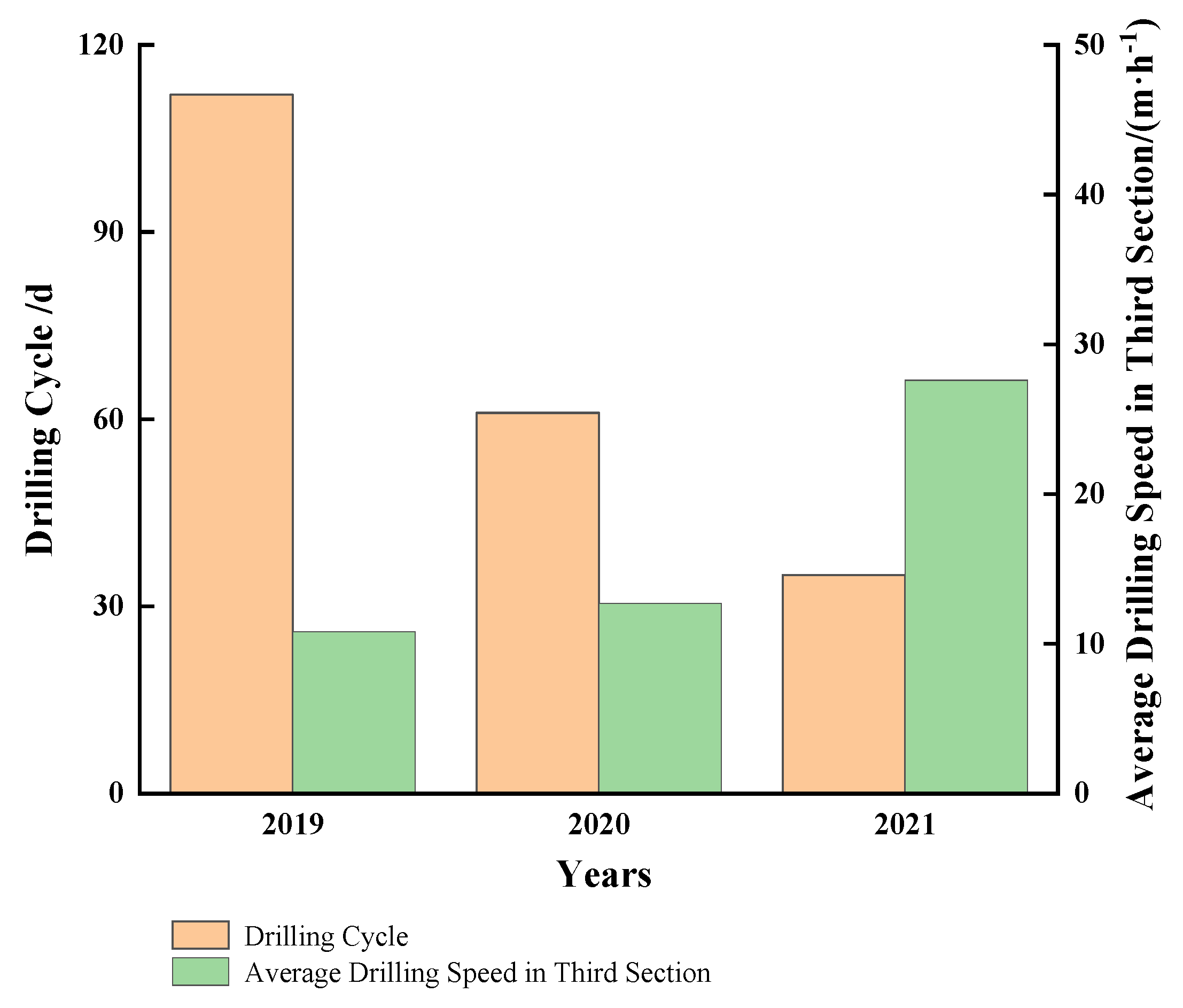
In the later stage of the G test area, after other platform wells and surrounding horizontal wells entered the Group Q, the drilling fluid density all increased to more than 1.60 g/cm3, and the downhole complexity was greatly reduced. From 2020 to 2021, the collapse pressure model of horizontal wells in layered shale established in this paper will be widely used in the two horizontal well test areas. The drilling cycle of horizontal wells will be greatly reduced and the average mechanical drilling speed will be significantly increased. Among them, well G3 has the best effect in 2021. The shortest drilling cycle of the third section is 13.77 days, and the average mechanical drilling speed is increased to 33.53 m/h, as shown in Figure 13.

Figure 13.
Annual comparisons of drilling period and ROP.
6. Conclusions
A prediction model for the wellbore collapse pressure of a horizontal well in layered continental shale oil is established, the mechanism of wellbore instability of a horizontal well in layered shale is studied, and the influence laws of different in situ stress conditions, wellbore trajectory, water content, bedding plane occurrence and other factors on collapse pressure are analyzed. Based on the calculation results and analyses of the case in the real field, the following conclusions can be drawn:
- The analysis shows that no matter under which in situ stress mechanism, the wellbore in the vertical well section is the most stable, and when the inclination angle is approximately 45°, the wellbore is most likely to be unstable.
- Changes in water content do not affect the most stable or unstable regions. Under the same conditions, the equivalent density of collapse pressure increases with the increase in water content.
- Since water-based drilling fluids are used to drill into layered shale formations, the hydration strain has a greater impact on the equivalent density of collapse pressure. Therefore, it is suggested that the influence of hydration on rock mechanical parameters and the influence of hydration expansion stress should be considered when designing the density of drilling fluid. During the drilling process, it is necessary to strictly control the filtration loss of the drilling fluid and improve the inhibition of the drilling fluid to reduce the water content of the formation, reduce the hydration strain, and ensure the stability of the wellbore.
- The results of this study are basically consistent with the previous research conclusions. However, the research results of this paper are more suitable for a layered continental shale oil horizontal well in the establishment of theoretical model and the final conclusion, and are demonstrated with field examples.
Author Contributions
Writing—review and editing, S.L.; writing—original draft preparation, K.L.; conceptualization, C.W. (Changhao Wang); resources, Y.W.; data curation, Y.J. and X.Z.; investigation, C.W. (Chunhua Wang). All authors have read and agreed to the published version of the manuscript.
Funding
This research was supported by the National natural science foundation of China (Grant No. 51874098).
Institutional Review Board Statement
Not applicable.
Informed Consent Statement
Not applicable.
Data Availability Statement
Not applicable.
Conflicts of Interest
On behalf of all the co-authors, the corresponding author states that there is no conflict of interest.
References
- Wen, C.; Wei, L. The Wellbore Stability Study in Bedding Shale Formation on the Condition of Plasticity. Chem. Technol. Fuels Oil 2022, 58, 220–231. [Google Scholar]
- Ewy, R.T. Wellbore Stability Predictions by Use of a Modified Lade Criterion. SPE Drill. Completion 1999, 14, 85–91. [Google Scholar] [CrossRef]
- Bo, K.H.; Jin, Y.; Lu, Y.H.; Liu, H.T.; Zhu, J.Z. A Quantitative Evaluation Method of Anti-Sloughing Drilling Fluid Inhibition for Deep Mudstone. Energies 2022, 15, 1226. [Google Scholar] [CrossRef]
- Ding, L.Q.; Wang, Z.Q.; Lv, J.G.; Wang, Y.; Liu, B.L. A New Model for Real-Time Prediction of Wellbore Stability Considering Elastic and Strength Anisotropy of Bedding Formation. Energies 2021, 15, 251. [Google Scholar] [CrossRef]
- Zhang, F.; Liu, H.B.; Cui, S.; Meng, Y.F.; Wang, J.J. Influence of the Weakening Effect of Drilling Fluid on Wellbore Stability in Anisotropic Shale Formation. Front. Phys.-Lausanne 2021, 9, 541. [Google Scholar] [CrossRef]
- Liu, Z.Y.; Pan, Z.J.; Li, S.B.; Zhang, L.G.; Wang, F.S.; Han, L.L.; Zhang, J.; Ma, Y.Y.; Li, H.; Li, W. Study on the effect of cemented natural fractures on hydraulic fracture propagation in volcanic reservoirs. Energy 2022, 241, 122845. [Google Scholar] [CrossRef]
- Cao, G.; Cheng, Q.; Liu, Y.; Bu, R.; Zhang, N.; Wang, P. Influencing Factors of Surfactant Stripping Crude Oil and Spontaneous Imbibition Mechanism of Surfactants in a Tight Reservoir. ACS Omega 2022, 7, 19010–19020. [Google Scholar] [CrossRef]
- Han, L.L.; Li, X.Z.; Guo, W.; Ju, W.; Cui, Y.; Liu, Z.Y.; Qian, C.; Shen, W.J. Characteristics and Dominant Factors for Natural Fractures in Deep Shale Gas Reservoirs: A Case Study of the Wufeng Longmaxi Formations in Luzhou Block, Southern China. Lithosphere 2022, 2022, 9662175. [Google Scholar] [CrossRef]
- Li, X.R.; Zhang, C.F.; Feng, Y.C.; Wei, Y.R.; Chen, X.P.; Weng, H.Y.; Deng, J.G. An integrated geomechanics approach to evaluate and manage wellbore stability in a deep graben formation in Tarim Basin. J. Pet. Sci. Eng. 2022, 208, 109391. [Google Scholar] [CrossRef]
- Gao, C.; Miska, S.; Yu, M.J.; Dokhani, V.; Ozbayoglu, E.; Takach, N. Experimental and numerical analysis of effective enhancement of wellbore stability in shales with nanoparticles. J. Nat. Gas Sci. Eng. 2021, 95, 104197. [Google Scholar] [CrossRef]
- Deng, J.; Liu, W.; Yu, B.; Tan, Q.; Yang, L. Pore pressure and stress distribution analysis around an inclined wellbore in a transversely isotropic formation based on the fully coupled chemo-thermo-poroelastic theory. J. Nat. Gas Sci. Eng. 2017, 40, 24–37. [Google Scholar]
- Epelle, E.I.; Gerogiorgis, D.I. A review of technological advances and open challenges for oil and gas drilling systems engineering. AIChE J. 2020, 66, e16842. [Google Scholar] [CrossRef]
- Tavallali, M.S.; Karimi, I.A.; Baxendale, D. Process systems engineering perspective on the planning and development of oil fields. AIChE J. 2016, 62, 2586–2604. [Google Scholar] [CrossRef]
- Asaka, M.; Holt, R.M. Anisotropic wellbore stability analysis: Impact on failure prediction. Rock Mech. Rock Eng. 2020, 54, 583–605. [Google Scholar] [CrossRef]
- Ding, Y.; Liu, X.J.; Luo, P.Y. The analytical model for horizontal wellbore stability in anisotropic shale reservoir. Geotech. Geol. Eng. 2020, 38, 5109–5126. [Google Scholar] [CrossRef]
- Ibrahim, A. A review of mathematical modelling approaches to tackling wellbore instability in shale formations. J. Nat. Gas Sci. Eng. 2021, 89, 103870. [Google Scholar] [CrossRef]
- Kang, Q.; Chen, M.; Yan, J.; Zhang, F. Stability model of borehole wall during the well test after acidizing treatment of sandstone reservoirs. Pet. Explor. Dev. 2011, 38, 589–593. [Google Scholar]
- Jaeger, J.C. Shear failure of anistropic rocks. Geol. Mag. 1960, 97, 65–72. [Google Scholar] [CrossRef]
- Liu, X.J.; Zeng, W.; Liang, L.X.; Lei, M. Wellbore stability analysis for horizontal wells in shale formations. J. Nat. Gas Sci. Eng. 2016, 31, 1–8. [Google Scholar] [CrossRef]
- Liu, J.; Yang, Z.; Sun, J.S.; Dai, Z.; You, Q. Experimental investigation on hydration mechanism of sichuan shale (China). J. Pet. Sci. Eng. 2021, 201, 108421. [Google Scholar] [CrossRef]
- Shuai, H.; Yang, C.H.; Zhang, B.P.; Guo, Y.T.; Wang, L.; Wei, Y.L. Experimental research on anisotropic properties of shale. Rock Soil Mech. 2015, 36, 609–616. [Google Scholar]
- Ma, Y.Y.; Li, S.B.; Zhang, L.G.; Liu, S.Z.; Liu, Z.Y.; Li, H.; Shi, E.X. Study on the effect of well layout schemes and fracture parameters on the heat extraction performance of enhanced geothermal system in fractured reservoir. Energy 2020, 202, 117811. [Google Scholar] [CrossRef]
- Aadnoy, B. Modeling of the stability of highly inclined boreholes in anisotropic rock formations. SPE Drill. Eng. 1988, 3, 259–268. [Google Scholar] [CrossRef]
- Ma, T.S.; Chen, P. A wellbore stability analysis model with chemical-mechanical coupling for shale gas reservoirs. J. Nat. Gas Sci. Eng. 2015, 26, 72–98. [Google Scholar] [CrossRef]
- Ma, T.S.; Chen, P.; Zhang, Q.B.; Zhao, J. A novel collapse pressure model with mechanical-chemical coupling in shale gas formations with multi-weakness planes. J. Nat. Gas Sci. Eng. 2016, 36, 1151–1177. [Google Scholar] [CrossRef]
- Ma, T.S.; Liu, Y.; Chen, P.; Wu, B.; Fu, J.; Guo, Z. Fracture-initiation pressure prediction for transversely isotropic formations. J. Pet. Sci. Eng. 2019, 176, 821–835. [Google Scholar] [CrossRef]
- Ma, T.S.; Zou, J.; Chen, P.; Liu, H. Investigation on the influence coupling drilling fluid and formation boundary on acoustic wave propagation in drill string. Geomech. Geophys. Geo-Energy Geo-Resour. 2020, 6, 35. [Google Scholar] [CrossRef]
- Peng, N.; Ma, T.S.; Chen, P.; Liu, Y. Pore pressure evaluation of formation testing while drilling under supercharged conditions. J. Petrol. Sci. Eng. 2021, 203, 108689. [Google Scholar] [CrossRef]
- Epelle, E.I.; Gerogiorgis, D.I. Optimal rate allocation for production and injection wells in an oil and gas field for enhanced profitability. AICHE J. 2019, 65, e16592. [Google Scholar] [CrossRef] [Green Version]
- Liang, C.; Chen, M.; Jin, Y.; Lu, Y. Wellbore stability model for shale gas reservoir considering the coupling of multi-weakness planes and porous flow. J. Nat. Gas Sci. Eng. 2014, 21, 364–378. [Google Scholar] [CrossRef]
- Lee, B.H. Borehole breakouts and compaction bands in two high porosity sandstones. Int. J. Rock Mech. Min. 2004, 41, 287–301. [Google Scholar]
- Epelle, E.I.; Gerogiorgis, D.I. A Multiperiod Optimisation Approach to Enhance Oil Field Productivity during Secondary Petroleum Production. Comput. Aided Chem. Eng. 2019, 46, 1651–1656. [Google Scholar]
- McConnell, D.R.; Zhang, Z.; Boswell, R. Review of progress in evaluating gas hydrate drilling hazards. Mar. Petrol. Geol. 2012, 34, 209–223. [Google Scholar] [CrossRef]
- Epelle, E.I.; Gerogiorgis, D.I. A multiparametric CFD analysis of multiphase annular flows for oil and gas drilling applications. Comput. Chem. Eng. 2017, 106, 645–661. [Google Scholar] [CrossRef] [Green Version]
- Li, S.B.; Liang, K.; Wang, C.H.; Jiao, Y.X.; Liu, H.G.; Wang, C.H. Study on the mechanism of anisotropic wellbore instability in continental shale in Songliao Basin. J. Petrol. Explor. Prod. Technol. 2022. [Google Scholar] [CrossRef]
- Zhi, G.; Chen, M.; Yan, J.; Shuai, Y.; Du, X. Experimental study of brittleness anisotropy of shale in triaxial compression. J. Nat. Gas Sci. Eng. 2016, 36, 510–518. [Google Scholar]
- Zeynali, M.E. Mechanical and physico-chemical aspects of wellbore stability during drilling operations. J. Pet. Sci. Eng. 2012, 82–83, 120–124. [Google Scholar] [CrossRef]
- Chen, P.; Ma, T.S.; Xia, H. A collapse pressure prediction model of horizontal shale gas wells with multiple weak planes. Nat. Gas Ind. 2015, 2, 101–107. [Google Scholar] [CrossRef] [Green Version]


Publisher’s Note: MDPI stays neutral with regard to jurisdictional claims in published maps and institutional affiliations. |
© 2022 by the authors. Licensee MDPI, Basel, Switzerland. This article is an open access article distributed under the terms and conditions of the Creative Commons Attribution (CC BY) license (https://creativecommons.org/licenses/by/4.0/).