Article

Determination and Analysis of Joule’s Heat and Temperature in an Electrically Conductive Plate Element Subject to Short-Term Induction Heating by a Non-Stationary Electromagnetic Field

1
Department of Mathematics, Institute of Applied Mathematics and Fundamental Sciences, Lviv Polytechnic National University, 79013 Lviv, Ukraine
2
Department of Computational Mathematics and Programming, Institute of Applied Mathematics and Fundamental Sciences, Lviv Polytechnic National University, 79013 Lviv, Ukraine
3
Faculty of Management, Comenius University Bratislava, 82005 Bratislava, Slovakia
*
Author to whom correspondence should be addressed.
Energies 2022, 15(14), 5250; https://doi.org/10.3390/en15145250
Submission received: 24 June 2022 / Revised: 14 July 2022 / Accepted: 19 July 2022 / Published: 20 July 2022
(This article belongs to the Section J2: Thermodynamics)

Abstract

:
We propose a mathematical model that allows us to determine the temperature field of a parallel-sided electrically conductive plate element subject to uniform non-stationary electromagnetic action. We formulate initial-boundary value problems to determine the parameters of the non-stationary electromagnetic field (NEMF) and the temperature. We develop a methodology to solve these initial-boundary value problems using the approximation of determining functions by cubic polynomials over thickness of the plate element. General solutions for the related Cauchy problems at uniform non-stationary electromagnetic action are obtained. Based on these solutions, the temporal variation of Joule’s heat and temperature in the plate element, subject to short-term induction heating by an NEMF in the mode of impulse modulating signal (MIMS), is analyzed. Temperature dependencies on the different values of electromagnetic field stress and on the different time duration were obtained. The choice of the carrier frequency of electromagnetic field oscillations is explained for the frequencies mostly used in industrial devices for inductive heating.

1. Introduction

The influence of force and heat factors on the distribution of temperature and mechanical tensions in plate elements of constructions is covered very well in the literature, in particular in [1,2]. However, the influence of electromagnetic factors on the thermal behaviour of electrically conductive plate elements has not been studied sufficiently [3,4]. Besides electrical devices, such plate elements are often used in ice-protection systems of planes and ships as actuators and sensors of mechanical fluctuations of various construction parts, to eliminate ice layering on these parts. In the aforesaid devices and systems, these elements work under the influence of NEMF that are by nature a sinusoidal electromagnetic force in the MIMS [5,6,7]. For technological processing of electrically conductive elements, short-term induction heating by a non-stationary electromagnetic field with temporal variation, depending on MIMS, is also used. Therefore, for reliable functioning of the elements mentioned above and for ensuring the normal operation of the elements under the aforesaid influence in MIMS, the modeling of their thermal behaviour is important.
Different industrial applications of the heating process of a nominally electrical conducting material with eddy currents induced by a varying electromagnetic field are considered in [8]. Monography [9] studied the fundamental aspects of the mathematical modelling and numerical approaches to solve electromagnetic and eddy current problems. Although many authors studied the Joule heat process, let us pay attention to some modern research. Ref. [10] considered the characteristics of the Joule heat process through a fine wire connecting two contacts. Paper [11] investigated parametric resonance of double-clamped micro-beams actuated electro-thermally by a time-dependent Joule’s heating. An analytical solution of the heat emission problem and heat flux is calculated via empirical correlations. Flux behaviour is studied by way of the finite difference method. Authors also studied the resonance characteristics analytically using the Galerkin approximations model with one degree of freedom reduced to the Mathieu–Duffin equation. The research results of Joule’s heating process in magnetofluid dynamics problems are described in [12,13,14]. In particular, in [12] a homotopic analysis method is applied to solve ordinary differential equations arising in the mathematical model with magnetofluid dynamics flow over a porous stretching sheet. Buongiorno’s model is used to study the adjoint influence of Joule’s heating and magnetofluid dynamics on nanofluid heat convection in [13]. Two-point ordinary boundary value differential equations are also numerically solved. In the paper [14], the results of the numerical simulation of the convective heat exchange in the electrically conducting liquid flowing between two isothermal spheres are presented. The corresponding equation for heat exchange modeling is obtained.
Various theoretical and applied problems arising in the inductive heating process are studied in [15,16,17]. The authors of [15] proposed the mathematical model to determine the temperature in a ball electroconductive valve under short-term inductive heat. To construct solutions of stated initial-boundary problems in electrodynamics and thermal conductivity a polynomial approximation of the determining functions by radial variable was used. Time changes in Joule heat and temperature were also analyzed numerically. Article [16] considered the problem of electromagnetic fields distribution and the stress-deformed state of an electroconductive body. The variational approach allows the establishment of the equation system in a general case. Via the numerical analysis in [17], induction heating processes of a rectangular substrate region are studied by way of a high-frequency electromagnetic field. The melting domain boundary is determined in Stefan approximation and solid phase growth region boundaries are calculated via the Kolmogorov theory of the metalcrystallization.
Papers [18,19,20,21] analyzed approaches to the numerical modelling of the inductive heating physical process. Considered models can be applied in metallurgy [18] and in shipbuilding (plate forming [19] and steel plate deformation [20]). Applications of heat generation during induction heating of process equipment have been presented using the example of ferromagnetic plates for hydraulic-frame presses assembly in [21]. A calculating procedure for three-dimensional fields of eddy currents in ferromagnetic bodies was proposed. The finite element-circuit coupled method in [22] enables us to compute electromagnetic parameters aiming to predict the deformation behaviour of metallic workpieces.
The aim of this paper is to build a mathematical model that would take into consideration the additional volume-distributed Joule’s heat Q. Joule’s heat is caused by the influence of NEMF besides the influence of natural surface heat and force factors on the working capacity and reliability of plate-type electrically conductive elements. The paper is also focused on developing a methodology for solving the related initial-boundary problems of electrodynamics and heat conductivity for determining the parameters of NEMF and temperature. Research is conducted into the temporal variation of Joule’s heat and temperature of the aforesaid plate element depending on the amplitude-frequency characteristics and the duration of non-stationary electromagnetic action in MIMS.

2. Mathematical Model. Problem Statement

Let us consider an electrically conductive plate element with a stable thickness 2 h within the Descartes system of coordinates x ,   y ,   z , where plane x O y coincides with the median surface of the plate element. The material of the plate element is uniform, isotropic, non-ferromagnetic, and its physical features are stable within the studied range of its thermal variation. The plate element is subject to the action of NEMF specified by the values of the touching component H y of the magnetic field strength vector H = 0 ;   H y ;   0 on its surfaces z   ±   h , which are in conditions of convective heat exchange with the environment and free from surface power load. The component H y z ,   t of vector H and temperature T z ,   t were chosen as determining functions for determining the thermal behaviour of the given plate element. These are the functions of the thickness variable z and the time variable t.
The mathematical model for determining the thermal behaviour of a plate element subject to short-term induction heating by NEMF consists of two stages. At stage 1, NEMF described by vector H and volume-distributed non-stationary sources of Joule’s heat Q are derived from Maxwell’s relations considering the specified initial-boundary conditions. At stage 2, the dynamic thermal field T is determined from the thermal conductivity equation, where the sources of Joule’s heat Q are volumetric non-stationary sources of heat, considering the specified initial and boundary conditions. Let us consider each stage in detail.

2.1. Determination of NEMF

The non-zero component H y z ,   t of vector H in the plate element is derived from the following equation (see [4,7]):
2 H y z 2 σ μ H y t = 0 ,
at boundary conditions on surfaces z = ± h of the plate element
H y h ,   t = H y t , H y h ,   t = H y + t
and the initial zero condition
H y z , 0 = 0 ,
H y t , H y + t are the specified functions of time t that describe a specific character of temporal variation of NEMF on surfaces z = ± h of the plate element, σ , μ are electric conductivity coefficient and magnetic permeability of the plate element material.
Using the H y z ,   t function that was derived from Equation (1) at the specified boundary (2) and initial (3) conditions, let us put down the specific density of Joule’s heat Q z ,   t as a ratio:
Q = 1 σ H y z 2 .

2.2. Determination of Thermal Field

Using the specific density of Joule’s heat Q z ,   t calculated in ratio (4), let us determine the distribution of heat T z ,   t in the plate element using the thermal-conductivity equation:
2 T z 2 1 κ T t = Q λ ;
in particular, at boundary conditions of thermal insulation on surfaces z = ± h of the plate element,
T ± h ,   t z = 0 ,
and the initial zero condition
T z ,   0 = 0 .
κ is the coefficient of thermal diffusivity and λ is the coefficient of thermal conductivity of the plate element material. Let us point out that, in the case of convective heat exchange with the environment, the aforesaid boundary conditions of thermal insulation (6) of the surfaces of the plate element should be replaced with the respective conditions of convective heat exchange.

2.3. Methodology of Solving the Formulated Initial-Boundary Problems

In order to solve the formulated initial-boundary problems of thermodynamics (1)–(3) and heat conductivity (5)–(7), let us approximate the distributions of determining functions H y z ,   t , T z ,   t by variable z by plate element thickness using cubic polynomials:
H y z ,   t = i = 0 3 a i t z i ,
T z ,   t = i = 0 3 b i t z i .
Coefficients a i t , b i t of the approximation polynomials (8), (9) are determined through the integral characteristics H y s t , T s t of the key functions H y z ,   t , T z ,   t ,
H y s t = h h H y z ,   t z s 1 d z , s = 1 , 2
T s t = h h T z ,   t z s 1 d z , s = 1 ,   2 ,
and the specified boundary conditions (2) imposed on the function H y z ,   t and the specified boundary conditions (6) imposed on the function T z ,   t on the surfaces z = ± h of the plate element. To find the integral characteristics H y s t and T s t , the original Equations (1) and (5) are integrated according to (10), (11) considering (8), (9).
As a result of transformations, the original initial-boundary problems for finding the determining function H y z ,   t and T z ,   t were reduced to corresponding Cauchy problems on the integral characteristics of these functions, which are described by the following equation systems:
d H y 1 t d t d 1 H y 1 t d 2 H y 2 t = d 3 H y t + d 4 H y + t , d H y 2 t d t d 5 H y 1 t d 6 H y 2 t = d 7 H y t + d 8 H y + t ,
d T 1 d t + d 1 T T 1 + d 2 T T 2 = W 1 t , d T 2 d t + d 3 T T 1 + d 4 T T 2 = W 2 t ,
and are solved at corresponding initial zero conditions according to (3), (7). The coefficients d 1 ÷ 8 , d 1 ÷ 4 T are determined through geometric parameters of the plate element and physical characteristics of its material. The expressions W s t s = 1 ,   2 are relevant for the right-hand side of the equation of heat conductivity (5) integrated according to (10).
Using Laplace’s integral transformation by time t, solutions of the Cauchy problems (12), (13) are written down as resultants of the functions describing the specified boundary conditions on the functions H y z ,   t , T z ,   t and homogeneous solutions of the equation systems (12), (13). As a result, after transformations, we obtain expressions of the component H y z ,   t :
H y z ,   t = i = 0 3 s = 1 2 a i s k = 1 2 0 t A s 1 k H y τ + + A s 2 k H y + τ e p k t τ d τ a i 3 H y t + a i 4 H y + t z i ,
and the temperature T z ,   t
T z ,   t = k = 0 3 s = 1 2 b k s m = 1 2 0 t B s 1 m W 1 τ + B s 2 m W 2 τ e p m t τ d τ z k .
A s 1 k , A s 2 k s = 1 ,   2 are expressions that depend on the roots p k k = 1 ,   2 of the characteristic equation of the system (12); B s 1 m , B s 2 m s = 1 ,   2 are expressions that correspond to heterogeneous solutions of the system (13) and depend on the roots p m m = 1 ,   2 of its characteristic equation.
Based on the obtained general solutions for the problems of electrodynamics and heat conductivity formulated above in the form of correlations (14), (4), (15) at uniform non-stationary action, let us write down solutions for the specific temporal variation under the influence of NEMF.

3. Results and Discussion

3.1. Research of Thermal Behaviour of the Plate Element Subject to Short-Term Conductive Heating by NEMF in MIMS

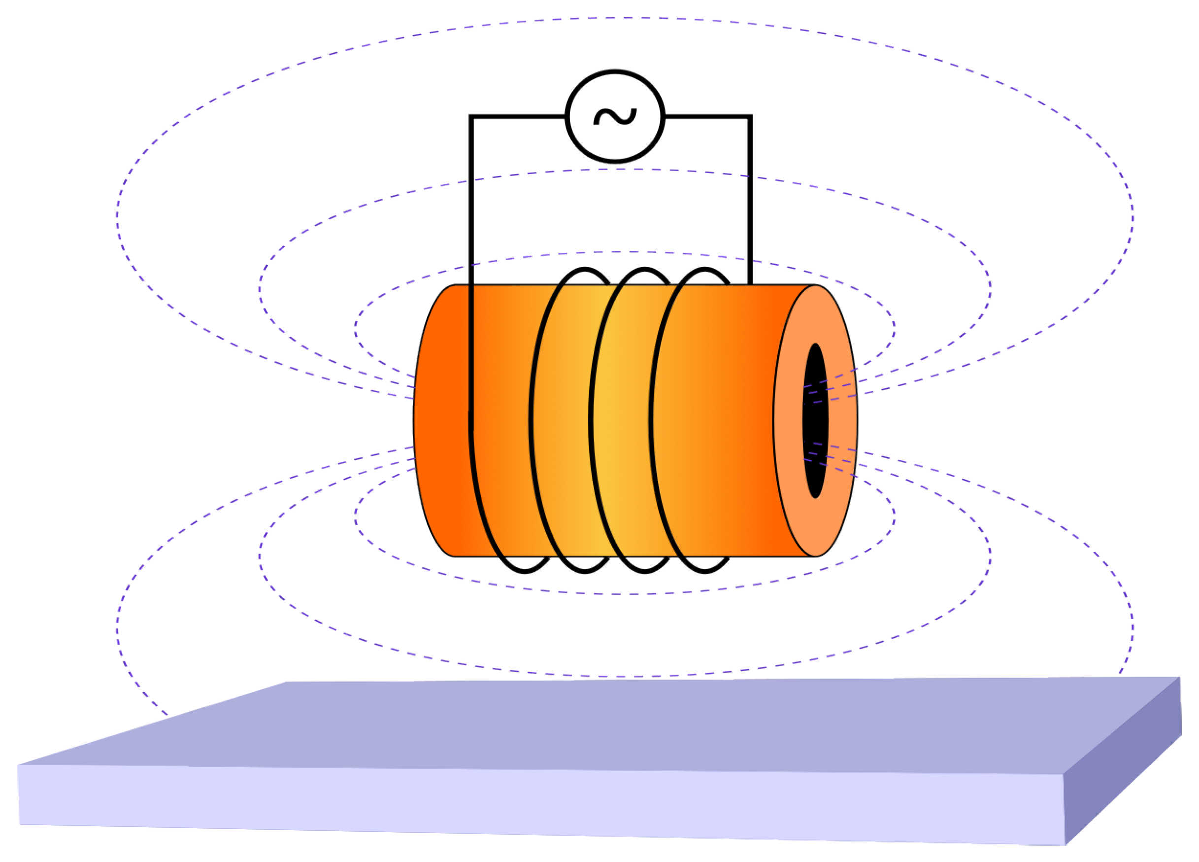
Induction heating of electrically conductive elements is performed using induced currents (Figure 1) by means of induction heating stations [23].
The action of induced currents at short-term induction heating by NEMF in MIMS is mathematically described by values of the component H y z ,   t on the surfaces z = ± h of the plate element, that can be written by the functions H y ± t in the form (14):
H y ± t = k 0 H 0 e β 1 t e β 2 t cos ω t .
k 0 is a normalizing factor, β 1 and β 2 are parameters that characterize the times of increase t i n c r and decrease t d e c r of the modulating impulse φ ( t ) = e β 1 t e β 2 t of duration t i respectively, H 0 is the maximum value of strength of the magnetic field in NEMF in MIMS that corresponds to the amplitude of carrier sinusoidal electromagnetic fluctuations with frequency ω .
Using (16) in the formulas (14), (4), (15), we write down the expressions of the component H y z ,   t , the non-stationary volumetric Joule’s heat Q, and the temperature T in the plate element subject to short-term induction heating by NEMF in MIMS. Expressions of the component H y z ,   t are the following:
H y z ,   t H 0 = cos ω t e β 1 t 9 2 1 z 2 α β 1 α β 1 2 + ω 2 1 2 1 3 z 2 +
+ e β 2 t 1 2 1 3 z 2 9 2 1 z 2 α β 2 α β 2 2 + ω 2 +
+ sin ω t 9 2 1 z 2 e β 1 t ω 1 α β 1 2 + ω 2 e β 2 t ω 1 α β 2 2 + ω 2 +
+ 9 2 1 z 2 α β 2 α β 2 2 + ω 2 α β 1 α β 1 2 + ω 2 e α t .
From (17), using relationships (4), one can get Joule’s heat Q z ,   t :
Q z ,   t H 0 2 = z 2 σ 0 h 2 D 1 e 2 β 1 t + D 2 e 2 α t + D 3 e 2 β 2 t + D 4 e β 1 + β 2 t + cos 2 ω t D 5 e 2 β 1 t +
+ D 6 e 2 β 2 t + D 7 e β 1 + β 2 t + sin 2 ω t D 8 e β 1 + β 2 t + D 9 e 2 β 2 t + D 10 e 2 β 1 t +
+ cos ω t D 11 e α + β 1 t + D 12 e α + β 2 t + sin ω t D 13 e α + β 1 t + D 14 e α + β 2 t ,
where
D 1 = 9 2 1 3 A 3 2 + 81 A 1 2 2 ; D 2 = 81 A 4 A 3 ;
D 3 = 9 2 1 + 3 A 4 2 + 81 A 2 2 2 ; D 4 = 9 1 3 A 3 1 + 3 A 4 81 A 1 A 2 ;
D 5 = 9 2 1 3 A 3 2 81 A 1 2 2 ; D 6 = 9 2 1 + 3 A 3 2 81 A 2 2 2 ;
D 7 = 9 1 3 A 3 1 + 3 A 4 81 A 1 A 2 ; D 8 = 3 1 3 A 3 A 2 3 1 + 3 A 4 A 1 ;
D 9 = 3 A 2 1 + 3 A 4 ; D 10 = 3 A 1 1 + 3 A 3 ;
D 11 = 54 A 3 A 4 1 3 A 3 ; D 12 = 54 A 3 A 4 1 + 3 A 4 ;
D 13 = 162 A 4 A 3 A 1 ; D 14 = 162 A 4 A 3 A 2 ;
A 1 = ω α β 1 2 + ω 2 ; A 2 = e β 2 t ω 1 α β 2 2 + ω 2 ;
A 3 = α β 1 α β 1 2 + ω 2 ; A 4 = α β 2 α β 2 2 + ω 2 ;
α = 3 σ μ h .
Taking into account expressions (15) and (9) we obtain T ( z ,   t ) as:
T z ,   t H 0 2 = κ σ λ h 2 z 2 D 1 1 e 2 β 1 t 2 β 1 + D 2 1 e 2 α t 2 α 1 + D 3 1 e 2 β 2 t 2 β 2 +
+ D 4 1 e 2 β 1 + β 2 t β 1 + β 2 +
+ D 5 e 2 β 1 t 4 β 1 2 + 4 ω 2 2 ω sin 2 ω t 2 β 1 cos 2 ω t 1 +
+ D 6 e 2 β 2 t 4 β 2 2 + 4 ω 2 2 ω sin 2 ω t 2 β 2 cos 2 ω t 1 +
+ D 7 e β 1 + β 2 t β 1 + β 2 2 + 4 ω 2 2 ω sin 2 ω t β 1 + β 2 cos 2 ω t 1 +
+ D 8 e β 1 + β 2 t β 1 + β 2 2 + 4 ω 2 2 ω cos 2 ω t 1 β 1 + β 2 sin 2 ω t +
+ D 9 e β 2 t 4 β 2 2 + 4 ω 2 2 ω cos 2 ω t 1 2 β 2 sin 2 ω t +
+ D 10 e β 1 t 4 β 1 2 + 4 ω 2 2 ω cos 2 ω t 1 2 β 1 sin 2 ω t +
+ D 11 e α + β 1 t α + β 1 2 + ω 2 ω sin 2 ω t α + β 1 cos 2 ω t 1 +
+ D 12 e α + β 2 t α + β 2 2 + ω 2 ω sin ω t α + β 2 cos ω t 1 +
+ D 13 e α + β 1 t α + β 1 2 + ω 2 α + β 1 ω sin ω t ω cos ω t 1 +
+ D 14 e α + β 2 t α + β 2 2 + ω 2 α + β 2 ω sin ω t ω cos ω t 1 .
Temperature expression (19) was written under the conditions of thermal isolation of the plate surfaces.

3.2. Numerical Analysis

To justify our theoretical analysis and show the efficiency of the proposed method we will perform in this subsection some numerical simulations. On the basis of the obtained solutions (18) and (19), numeric analysis of Joule’s heat Q and temperature T in an electrically conductive plate element with the thickness of 2 h = 2 mm made of stainless steel subject to short-term induction heating by the NEMF under study was realized. For obtained numerical analysis the next values were taken: σ = 0.135 · 10 7 ( Ω · m ) 1 , κ = 0.422 · 10 5 m 2 / s , λ = 0.167 · 10 2 W / ( m · K ) and μ = 12.57 · 10 7 ( H / m ) . The following durations of electromagnetic action (16) t i were used: t i = 10 4 s ; t i = 10 2 s ; t i = 1 s ; t i = 10 s ; t i = 100 s .
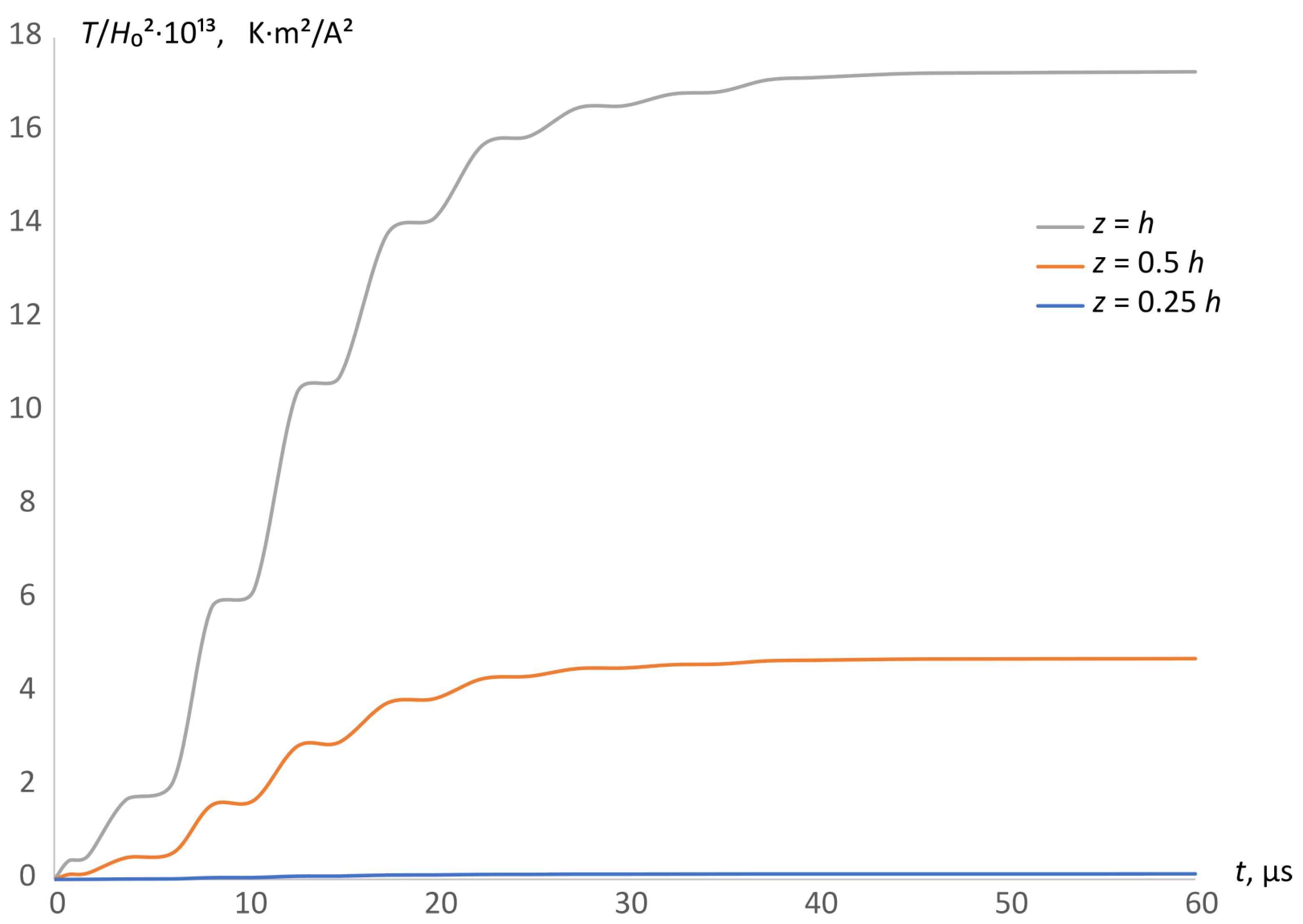
Figure 2 and Figure 3 illustrate changes in time of the magnitudes Q and T at carrier signal frequency ω = 6.28 · 10 5 rad s (beyond the circle of resonance frequencies ω r , k , where k is NEMF resonance frequency order [7]) for the duration of electromagnetic action t i = 100 μ s . At this duration, 10 periods f = 2 π ω of electromagnetic fluctuations of this frequency take place.
Lines on Figure 2 and Figure 3 correspond to the values of the thickness coordinate z = h (in grey colour), z = 0.5 h (in orange colour), z = 0.25 h (in blue colour). It was established that Joule’s heat Q and temperature T reach their maximum values on the surfaces of the plate element z = ± h at the moments of time t 0 , 1 t i and t 0.5 t i respectively.
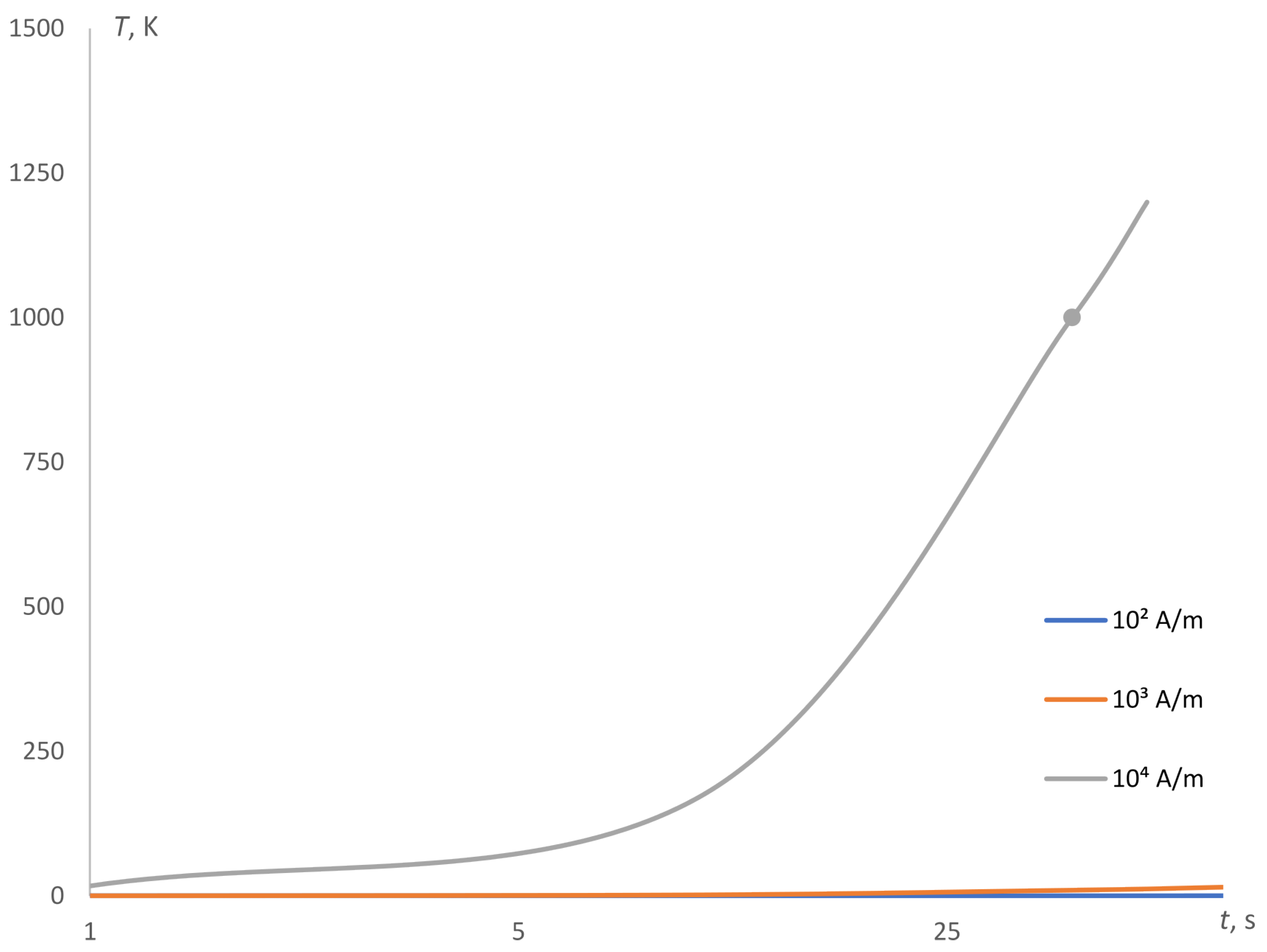
Figure 4 shows the dependence of temperature maximum values on time duration of inductive heating NEMF t i with different values of strength H 0 with respect to the amplitude of carrier electromagnetic fluctuations at the frequency value ω = 6.28 · 10 5 rad / s . Figure 5 shows dependence of temperature maximum values on strength H 0 with different time duration of inductive heating NEMF t i . The following values were taken: t i = 1 s , t i = 10 s , t i = 50 s . Generators of high frequency electromagnetic fluctuations for the inductive heating usually operate with the considered strength values H 0 = 10 2 A / m , H 0 = 10 3 A / m , H 0 = 10 4 A / m .
Note that in case of using the carrier sinusoidal electromagnetic fluctuations frequency value of ω = 4.678 · 10 6 rad / s , one can obtain 77 periods of electromagnetic fluctuations NEMF at time t i = 100 μ s approximately.

4. Conclusions

Contrary to the known methods of study, inductive heating under stationary electromagnetic fields action and with the aim to develop research in [3,4], the authors analyzed inductive heating corresponding to NEMF action with MIMS, taking into account the moments to switch the high-frequency oscillations generator off and on. The main idea of the paper is the obtaining of the general solutions for thermodynamic and thermal transfer problems under the NEMF action and non-stationary volume distributed heating sources. The adequacy of the analyzed numerical studies is based on the physical models describing electromagnetic and thermal fields.
1
There are obtained parameters (time duration and strength) of the optimal modes at short-term induction heating of an electrically conductive alloy steel plate element with chrome, nickel and titanium:
(a)
Time duration of inductive heating NEMF t i values are found within the limits from 10 s to 40–50 s;
(b)
The value of electromagnetic field strength H 0 is established approximately as 10 4 A/m as well;
(c)
Strength value H 0 = 10 4 A/m is optimal for the sufficient temperature level under the short-term inductive heating. In particular, while t i < 40–50 s, the melting temperature of the plate element cannot be obtained. That is why the considered mathematical model is valid for low temperatures;
(d)
Minor values H 0 = 10 2 A/m or H 0 = 10 3 A/m are not effective for inductive short-term heating.
2
In the case of stationary electromagnetic fields, the strength is mostly used with values H 0 = 10 2 –10 3 A/m. So the heating process needs a substantially longer time duration in comparison to H 0 = 10 4 A/m under NEMF action to achieve the necessary temperature values. In particular, we are interested in temperature T = 1000 K because it is widely used in technological thermal heating. NEMF, perhaps, does not lead to an essential energies economy, but we can state that the short time duration is an advantage of our method. Besides that, under short-time heating mode it is easier to satisfy the necessary strength value H 0 = 10 4 A/m.
3
Analytical function φ ( t ) takes into account the moments of switching on and off for generators of high frequency electromagnetic fluctuations.
4
Qualitative and quantitative results in the paper are applicable to describing short-time induction heating modes of the electrical conductive plate elements in different devices while technologically processing. Finally, it is worth mentioning that the proposed method can be used to study similar problems.
5
The obtained NEMF characteristics may serve as a theoretical basis for forecasting the rational modes of electrically conductive plate element processing by induction heating and can also be used to predict the optimal parameters (frequency, duration of thermal heating, strength) of the electromagnetic field and choose the rational mode of thermal functioning of the plate element as a constructive part of the technological equipment, in particular in aerospace vehicles and robotized systems etc.
The authors’ next step would be to study the electromagnetic and heating properties of bimetal plate elements under the short-term inductive heating NEMF.

Author Contributions

Conceptualization, R.M., P.P.; methodology R.M., P.P., M.V.; software, I.K., Ľ.Š.; validation, I.K., Ľ.Š.; investigation, P.P., M.V.; writing—original draft preparation, M.V., Ľ.Š.; writing—review and editing, R.M., P.P.; visualization, I.K., Ľ.Š.; project administration, R.M., P.P.; funding acquisition, Ľ.Š. All authors have read and agreed to the published version of the manuscript.

Funding

This research was supported by the National Research Foundation of Ukraine # 2021.01/0103.

Institutional Review Board Statement

Not applicable.

Informed Consent Statement

Not applicable.

Data Availability Statement

Not applicable.

Conflicts of Interest

The authors declare no conflict of interest.

Abbreviations

The following abbreviations are used in this manuscript:
NEMFNon-stationary electromagnetic field
MIMSMode of impulse modulating signal

References

  1. Serpilli, M.; Dumont, S.; Rizzoni, R.; Lebon, F. Interface Models in Coupled Thermoelasticity. Technologies 2021, 9, 17. [Google Scholar] [CrossRef]
  2. Hetnarski, R. Encyclopedia of Thermal Stresses; Springer: Dordrecht, The Netherlands, 2014. [Google Scholar] [CrossRef] [Green Version]
  3. Batygin, Y.; Shinderuk, S.; Chaplygin, E. Mutual influence of currents in a flat inductor system with solenoid between two massive conductors. Electr. Eng. Electromech. 2021, 6, 25–30. [Google Scholar] [CrossRef]
  4. Asai, S. Electromagnetic Processing of Materials; Springer: Dordrecht, The Netherlands, 2012. [Google Scholar] [CrossRef] [Green Version]
  5. Smetana, M.; Capova, K.; Chudacik, V.; Palcek, P.; Oravcova, M. Influence of the Heat Treatment on Magnetic Properties of Austenitic Steels. Stud. Appl. Electromagn. Mech. 2017, 42, 83–90. [Google Scholar] [CrossRef]
  6. Montoya, E.; Sebastian, T.; Schultheiss, H.; Heinrich, B.; Camley, R.; Celinski, Z. Magnetization Dynamics. In Handbook of Surface Science; North-Holland: Amsterdam, The Netherlands, 2015; Volume 5, pp. 113–167. [Google Scholar] [CrossRef]
  7. Hachkevych, O.; Musii, R. Mathematical modeling in thermomechanics of electroconductive bodies under the action of the pulsed electromagnetic fields with modulation of amplitude. Math. Model. Comput. 2019, 6, 30–36. [Google Scholar] [CrossRef]
  8. Bobart, G.F. Induction heating. AccessScience. 2020. Available online: https://www.accessscience.com/content/341500 (accessed on 2 June 2022).
  9. Touzani, R.; Rappaz, J. Mathematical Models for Eddy Currents and Magnetostatics With Selected Applications; Springer: Dordrecht, The Netherlands, 2013. [Google Scholar] [CrossRef]
  10. Gantsevich, S.; Gurevich, V. Joule heat release during current flow through a nanowire. Phys. Solid State 2016, 58, 1711–1715. [Google Scholar] [CrossRef]
  11. Torteman, B.; Kessler, Y.; Liberzon, A. Micro-beam resonator parametrically excited by electro-thermal Joule’s heating and its use as a flow sensor. Nonlinear Dyn. 2019, 98, 3051–3065. [Google Scholar] [CrossRef]
  12. Ibrahim, S.M.; Kumar, P.V.; Lorenzini, G.; Lorenzini, E. Influence of Joule Heating and Heat Source on Radiative MHD Flow over a Stretching Porous Sheet with Power-Law Heat Flux. J. Engin. Thermophys. 2019, 28, 332–344. [Google Scholar] [CrossRef]
  13. Moshizi, S.A.; Pop, I. Conjugated Effect of Joule Heating and Magnetohydrodynamic on Laminar Convective Heat Transfer of Nanofluids Inside a Concentric Annulus in the Presence of Slip Condition. Int. J. Thermophys. 2016, 37, 72. [Google Scholar] [CrossRef]
  14. Solov’ev, S. Influence of Joule Dissipation on Heat Exchange and Magnetic Hydrodynamics of Liquid in a Spherical Layer. Part I. J. Eng. Phys. Thermophy 2017, 90, 1251–1265. [Google Scholar] [CrossRef]
  15. Musii, R.; Melnyk, N.; Nakonechnyi, A.; Goshko, L.; Bandyrskyi, B. Determination and analysis of the temperature field of a continuous electrically conductive ball with short-term induction heating. Appl. Quest. Math. Model. 2021, 4, 149–158. (In Ukrainian) [Google Scholar] [CrossRef]
  16. Altenbach, H.; Naumenko, K.; Lavinsky, D.; Konkin, V. Variational Formulation of Problems of Thermodeformation of Electrically Conductive Bodies in Electromagnetic Field. In Bulletin of NTU “KhPI”: Series “Dynamics and Strength of Machines”. 2019, pp. 3–6. Available online: http://jdsm.khpi.edu.ua/article/view/187409 (accessed on 2 June 2022). (In Ukrainian).
  17. Popov, V.; Shchukin, V. Numerical Simulation of Metal Surface Layer Modification Using High-Frequency Induction Heating. Inorg. Mater. Appl. Res 2019, 10, 616–621. [Google Scholar] [CrossRef]
  18. Bermúdez, A.; Gómez, D.; Muñiz, M.; Salgado, P.; Vázquez, R. Numerical Modelling of Industrial Induction. In Advances in Induction and Microwave Heating of Mineral and Organic Materials; IntechOpen: London, UK, 2011; Chapter 4. [Google Scholar] [CrossRef] [Green Version]
  19. Yi, H.Z.B.; Wang, J.; Zheng, X. Preliminary investigation on plate bending with multiple-line induction heating. J. Mar. Sci. Technol. 2020, 25, 455–466. [Google Scholar] [CrossRef]
  20. Bae, K.; Yang, Y.; Hyun, C. Analysis of triangle heating technique using high frequency induction heating in forming process of steel plate. Int. J. Precis. Eng. Manuf. 2012, 13, 539–545. [Google Scholar] [CrossRef]
  21. Glebov, A.; Karpov, S.; Karpushkin, S. Modeling of Three-Dimensional Fields of Eddy Currents during Induction Heating of Process Equipment. Russ. Electr. Engin. 2018, 89, 204–209. [Google Scholar] [CrossRef]
  22. Cao, Q.; Li, Z.; Lai, Z. Analysis of the effect of an electrically conductive die on electromagnetic sheet metal forming process using the finite element-circuit coupled method. Int. J. Adv. Manuf. Technol. 2019, 101, 549–563. [Google Scholar] [CrossRef]
  23. Madzharov, N.D.; Nemkov, V.S. Technological inductive power transfer systems. J. Electr. Eng. 2017, 68, 235–244. [Google Scholar] [CrossRef] [Green Version]
Figure 1. Induction heating using induced currents.
Energies 15 05250 g001
Figure 2. Thermal variation of Joule’s heat in the plate element at ω = 6.28 · 10 5 rad / s .
Energies 15 05250 g002
Figure 3. Thermal variation of temperature T in the plate element at ω = 6.28 · 10 5 rad / s .
Energies 15 05250 g003
Figure 4. Temperature dependence on time duration of inductive heating NEMF t i with different values of H 0 .
Energies 15 05250 g004
Figure 5. Temperature dependence on strength H 0 with different values of time duration of inductive heating NEMF t i .
Energies 15 05250 g005
Publisher’s Note: MDPI stays neutral with regard to jurisdictional claims in published maps and institutional affiliations.