
Review of Solid-State Transformer Applications on Electric Vehicle DC Ultra-Fast Charging Station


Department of Electrical Electronics and Automatic Control Engineering, Universitat Rovira i Virgili, 43007 Tarragona, Spain
*
Author to whom correspondence should be addressed.
Energies 2022, 15(15), 5602; https://doi.org/10.3390/en15155602
Submission received: 26 June 2022
/
Revised: 15 July 2022
/
Accepted: 27 July 2022
/
Published: 2 August 2022
(This article belongs to the Special Issue Electric Vehicle Charging: Social and Technical Issues)
Abstract
:The emergence of DC fast chargers for electric vehicle batteries (EVBs) has prompted the design of ad-hoc microgrids (MGs), in which the use of a solid-state transformer (SST) instead of a low-frequency service transformer can increase the efficiency and reduce the volume and weight of the MG electrical architecture. Mimicking a conventional gasoline station in terms of service duration and service simultaneity to several customers has led to the notion of ultra-fast chargers, in which the charging time is less than 10 min and the MG power is higher than 350 kW. This survey reviews the state-of-the-art of DC ultra-fast charging stations, SST transformers, and DC ultra-fast charging stations based on SST. Ultra-fast charging definition and its requirements are analyzed, and SST characteristics and applications together with the configuration of power electronic converters in SST-based ultra-fast charging stations are described. A new classification of topologies for DC SST-based ultra-fast charging stations is proposed considering input power, delta/wye connections, number of output ports, and power electronic converters. More than 250 published papers from the recent literature have been reviewed to identify the common understandings, practical implementation challenges, and research opportunities in the application of DC ultra-fast charging in EVs. In particular, the works published over the last three years about SST-based DC ultra-fast charging have been reviewed.
1. Introduction
The technical requirements of battery fast charging cannot be fulfilled by the electric vehicle (EV) onboard charger, which is connected to a single-phase or three-phase AC domestic supply [1]. To decrease the charging time, a huge amount of DC power is required [2], so it is mandatory to supply the charging station microgrid (MG) from a medium voltage (MV) AC source. This connection could be carried out through a low frequency transformer (LFT), a hybrid transformer (HT), or a solid-state transformer (SST) [3]. It is worth mentioning that the notion of SST is used here in a broad sense, which means that it can be considered as any conversion structure implemented with switching converters that is capable of transforming MV-AC into DC in the region between 200 V and 500 V.
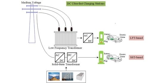
This paper is motivated by the identification of the state of the art of ultra-fast charging stations, which can be based either on LFT or SST as illustrated in Figure 1a,b, respectively. It is apparent in the figure that the DC SST-based ultra-fast charging station allows the integration of renewable energies, energy storage, and AC/DC loads, so the resulting electrical architecture can be considered as an AC/DC/Hybrid MG. In a clear-cut contrast, a LFT-based ultra-fast charging station does not facilitate the integration of renewable energies but offers the advantage of high reliability at the expense of a relatively big size (Table 1).
1.1. State of the Art
Carbon dioxide emissions have a direct impact on climate changing and global warming. Currently, a significant portion of carbon dioxide emissions is issued by fossil fuel vehicles (FFV) [4]. According to statistics, the portion of transportation in carbon production is more than 20% [5]. Therefore, FFVs are being replaced by EVs. The EVs have higher efficiency and less maintenance in comparison with FFVs [6], which can be refueled within two minutes. The charging time of EVs is much longer since they are normally charged in the residential distribution network with AC on-board chargers (OBCs) (120–240 V) [1]. The provided power through these slow OBCs is 1.44–22 kW [7]. Therefore, for a 100 kWh battery, it takes more than 5 h to be fully charged, which is not satisfiable for long trips and increases the anxiety of the drivers. The advancement of OBCs is still continuing, but there are some barriers to high-power AC OBCs, such as charger size, cost, weight, maintenance, and EV safety requirements [8]. The next solution is to utilize an integrated charging structure by means of a traction motor, which was previously used in the railway traction industry [9]. Three-phase electrical motor winding can achieve high power and charge the battery through the inverse operation of the drive inverter [10]. However, this technique has some adverse effects on an EV, such as high stress on the traction system, torque production, acoustic noise, and mechanical vibrations, which reduce the lifespan of the whole EV [11]. Another alternative solution is to build a DC ultra-fast charging station like traditional fuel stations to directly communicate and charge the EV battery [2]. In a DC ultra-fast charging station, the charging time of EVs should significantly decrease to be competitive with traditional fuel stations. In order to decrease an EV’s charging time, the amount of the delivered power to the EV’s battery charger should increase. Until now, the maximum DC power delivered to the EV battery in the market is 250 kW. The limit is due to the high temperature [12] and state of health (SOH) issues of the battery [13]. However, it is foreseen to reach 1200 kW maximum delivered DC power [14] as a result of advancements in battery structure design, vehicle electrical architecture, and material in the near future [15].
In order to build a DC ultra-fast charging station, this should be fed by MV transmission lines. In order to decrease the voltage level to the one required for the EV’s battery chargers, LFT, HT [16], and SST [17] can be used in the charging stations. The first suffers from low efficiency, bulky size, high maintenance cost, slow dynamics, limited controllability, and lack of plug-and-play functionality [18]. These shortcomings make LFT less functional in DC ultra-fast charging stations. The HT is the combination of partially-rated power converters, normally between 5–20% of the rated power, in the input or output of a LFT. The HT also suffers from a bulky size, but it is more efficient and controllable than LFT. A 2 kVA small-scale HT is experimentally validated in [19]. The last promising solution to change the MV level into the EV battery charger voltage level is to utilize an SST. It has a higher degree of control freedom, storage integration capability, harmonic filtering, smaller size, fault current limitation, bidirectional power flow capability, and higher operational frequency [20]. In addition, the advancement of high-voltage high-power silicon carbide (SiC) and gallium nitride (GaN) devices has paved the way for the extensive use of SSTs in high-power applications [21]. The performances of SST, HT with integrated energy storage, and LFT have been technically and economically compared in [3] for distribution grid applications. Since the use of SST in power systems is still new, there exist many issues and challenges, especially in the DC ultra-fast charging applications, which should be addressed.
1.2. Objectives of the Paper
The aim of this paper is to provide a step-by-step comprehensive review about DC ultra-fast charging stations where SST is used. This paper provides information about ultra-fast charging definitions and requirements, SST definition, structure, and challenges, as well as DC SST-based ultra-fast charging station configurations, control, and challenges. A new topology configuration for a DC SST-based ultra-fast charging station is classified based on the input type, number of the output ports, and the converter type. The DC SST-based ultra-fast charging station is considered as an MG, and possible challenges of MGs are discussed.
1.3. Organization of the Paper
The rest of this paper is organized as follows. In Section 3, a complete description of the battery charging is surveyed. Section 3 describes the state of the art of DC ultra-fast charging stations. In Section 4, a comprehensive review of SST topologies is presented. Section 5 investigates all the technical and research works performed in DC SST-based ultra-fast charging stations. Finally, Section 6 concludes the paper.
2. Battery Charging Definition and Barriers
The battery charging procedure has different definitions and requirements. One of the most important definitions is the battery C rating. The battery capacity is usually rated at 1C (1C current) [22]. As an example, a 400 V battery with 100 kWh capacity can be charged or discharged with 250 A within one hour. This means that with the use of 1 kA of current, the battery can be recharged in 15 min. Therefore, an increase in C rating yields a faster charging or discharging time. However, C rate increase has technically some limitations, including increases in internal energy losses, battery thermal tolerance, and reducing battery’s life-cycle [23]. The 6C rate of charging is considered as an ultra-fast charging method according to the US Department of Energy (DOE) [24]. As a result, a trade-off exists between ultra-fast charging and battery health [25].
The battery discharging procedure is related to the demanded power and is not controllable. However, the battery charging task can be controlled with optimal charging strategies. Monitoring and estimating the state of charge (SOC) and the state of health (SOH) play a significant role in battery charging methods [26,27]. Different charging strategies have been proposed in the literature for lithium-ion (Li-ion) batteries [28,29]. Some of them are independent from the battery chemical model and dynamic, e.g., constant-current (CC) [30], constant-current constant-voltage (CCCV) [31], multi-stage CCCV [32], and pulse charging techniques [33]. The typical CCCV charging method is illustrated in Figure 2 [34]. Some others are based on empirical models [35], including circuit-based models [36] and neural network models [37]. The pseudo-two-dimensional (P2D) [38] and single particle model (SPM) [39,40] are the most usable circuit-based models for battery charging optimization, battery SOC prediction [41], and control. The last charging approach is based on the battery electrochemical model, in which all the physical parameters are observed. This approach is the most complicated and accurate among others. However, due to the high computational burden, its real-time charging controller implementation is not practical yet.
To summarize, the optimal charging strategies should be as fast as possible while the temperature limitation and battery SOH are maintained within the desirable range [42]. In EV application, the responsible part for the optimal operation of battery charging is the battery management system (BMS), which analyses and monitors all the information taken from the EV battery pack [43]. The BMS cooperates with the battery charging circuit through the exchange of data in order to control the injected current and voltage to the battery cells [44]. Battery charging circuits can be placed on-board inside EVs [45], off-board in the charging stations, or wireless (inductive) with unidirectional or bidirectional power flow [46]. The OBCs connect to the residential single-phase or three-phase AC voltage, and the off-board chargers connect to the DC voltages with different kinds of cables, some of which are illustrated in Figure 3. The connectors are categorized into four levels according to their maximum power transfer capability. The levels 1 and 2 AC chargers are supplied with 120 V and 240 V AC, respectively [7]. In the market, the maximum supplied power for the battery is 1.92 kW in level 1 and 19.2 kW in level 2. The International Electrotechnical Commission (IEC) has published standard requirements for EV plugs, socket-outlets, connectors, and inlets (IEC 62196) [47]. According to the IEC 62196-2:2016 [48], the maximum power for the level 2 on-board charging mode is 33.6 kW (480 V AC, 70 A). In the pre-release version of IEC 62196-1:2022 PRV [49], the AC charger maximum power was determined as 172.5 kW (690 V AC, 250 A) and the DC ultra-fast charging maximum power was 1200 kW (1500 V DC, 800 A). Table 2 shows some of the charging connectors’ voltage and power ratings existing in the market categorized by their charging speed. It should be noted that, due to the weight and size limitation in EVs, the utilization of OBCs is limited to the low-voltage low-power applications [50]. Therefore, they cannot be charged sufficiently quickly to mimic the same refueling experience in conventional gasoline stations. Commercial on-board charging including dedicated and integrated as well as off-board charging infrastructures are surveyed in [51]. Different charging topologies such as bidirectional active front end (AFE) [52], interleaved unidirectional charger topology [53], and bridgeless power factor correction (PFC) stages [54] are reported in detail in [55].
To increase the distance traveled by the EVs, the first solution is to raise the EV’s battery capacity, which yields a bigger EV size, cost, and weight [56]. Different types of batteries have been used in EVs such as lead–acid (Pb–acid), nickel–cadmium (NiCd), nickel–metal–hydrid (NiMH), Li-ion, Li-ion polymer, and sodium–nickel–chloride (NaNiCl) [57]. Among these, Li-ion batteries have been extensively commercialized in the EV industry thanks to their higher energy density, longer life cycle, and lower maintenance [58]. The EV’s battery characteristics for some vehicle manufacturers are shown in Table 3 [59,60,61]. As can be observed from this table, the battery capacity and supercharger maximum power reach 103 kWh and 250 kW, respectively, which reduces the full-charging time to within 30 min. From a material point of view, the fast charging of Li-ion batteries is reviewed in [62]. The research is still ongoing in the context of material engineering for the advancement of energy storage systems and to improve their energy density. Their charging time should be reduced to the range 5–10 min to be competitive with conventional fuel stations.
Another solution is to build a DC ultra-fast charging station that is like traditional gasoline stations [63]. This can give the opportunity to the drivers to frequently charge their vehicles in urban or interurban DC ultra-fast charging stations. From an economical point of view, building DC ultra-fast charging stations is more appropriate [8], as detailed in the next section.
3. DC Ultra-Fast Charging Station
Different possible configurations of DC ultra-fast charging stations are AC-coupled, DC-coupled, and hybrid-coupled. These are shown in Figure 4. In this figure, all the power flows could be bidirectional to satisfy vehicle-to-grid (V2G), vehicle-to-home (V2H), and vehicle-to-vehicle (V2V) applications in the future smart grids [64]. To deliver the power to or from an EV, bidirectional power electronic converters are used, which are comprehensively reported in [65]. An example of an AC-coupled DC ultra-fast charging station is in Mountain View, California, with six superchargers and a 400 kWh integrated energy storage for load shaving within peak hours. The AC-coupled DC ultra-fast charging station has some advantages such as appropriate converter technology, switchgear, protection devices, and well-established standards. The only disadvantages of AC-coupled stations is the huge amount of used power converters in order to integrate with the DC systems, which leads to more complex and less efficient systems. In addition, some control challenges appear in the island mode of operation such as reactive power control, inverter synchronization, and voltage/frequency control. The DC-coupled configuration, shown in Figure 4b, has less conversion stages, higher efficiency, and a simpler control structure, although it has a complex protection scheme and non-standardized metering [66]. Moreover, the integration of renewable energies and energy storage is more simple. In addition, the proposed structure of a DC ultra-fast charging station with a bipolar DC bus in [67] can solve the grounding issue of the DC network [68,69]. In the hybrid-coupled charging station, shown in Figure 4c, which is a combination of a DC-fast charger and single-phase and three-phase AC chargers, the system suffers from load nonlinearity problems due to the use of power electronic converters as well as unbalance issues due to the connection to single-phase chargers or different fast charging pilot power requirements.
As reported previously in Table 3, the supercharger maximum power existing in the EV market is 250 kW. Consider this value as the maximum peak charging power; therefore, the maximum peak power required in the eight-slot DC-coupled DC ultra-fast charging station (Figure 4b) would be 2 MW whenever all the pilots are simultaneously charging the EVs with the lowest SOC. This is the worst-case scenario that could happen in the charging station. It should be considered that, due to the differences in the SOCs of EV batteries, the charging power delivered to each battery could be different (see Figure 2).
As shown in Figure 4, the DC ultra-fast charging station has three power stages, which are listed below. The power stages and utilized power electronic converters inside the EVs can be found in [70].
3.1. Power Stage 1
The first power stage is the voltage level change. The huge amount of power required in the DC ultra-fast charging station should directly be provided from the MV distribution line. Since the battery chargers work at less than 1000 V, a transformer is required to step-down the voltage level. Different types of transformers are used in the literature to step-down the voltage level in power systems, including LFT, SST, and HT [71]. These are shown in Figure 5 [3].
The LFTs are bulky in size, weighty, and suffer from a high installation cost. There is no control freedom in the input/output voltage/current of the LFTs. Although with mechanical tap changers, the voltages can be controlled to a limited extent, this is not sufficient in the fast voltage fluctuations of modern power systems in which the penetration of intermittent renewable energies, EVs, and DC ultra-fast charging stations is high. An alternative solution is to use HT, which is the combination of a power electronic converter in the input/output of the LFTs (Figure 4c). Thanks to the power converter installation, the integration of energy storage in the HT DC link is possible. The converter power rating is usually between 5–20%, which gives controllability to some extent. However, HT is also bulky and weighty. Another alternative solution is to utilize SST, which can provide full control freedom in the input/output voltage/current such as reactive power control, voltage regulation, and harmonic control. Furthermore, the integration of energy storage and renewable energies is very simple. The SST has advantages including a reduced overall cost and compact size, which are explained in detail in the next section. However, due to the switching and conduction losses in SSTs, their efficiency is lower than the LFTs [72]. The research is still open to improve the SST efficiency specifically in high-power applications.
3.2. Power Stage 2
The second power stage in the DC ultra-fast charging station is AC to DC conversion, which is responsible for the PFC [73]. In this power stage, the converter rectifies the three-phase input AC voltage to a fixed output voltage in the DC link provided that the power quality is desirable on the grid side. Different kinds of power converters are used for this power stage. The AFE rectifier, which is also called an active pulse width modulated (PWM) rectifier, is one of the most used three-phase power converter for this power stage thanks to its high reliability and simplicity. It is used in boost [74], buck [75], and buck–boost [76] modes of operation. Other used simple topologies that can keep the system modularity are half bridge (HB), full bridge (FB), and four-switch buck–boost converter [77] separately used in each phase. Other proposed topologies are multilevel [78], such as the cascaded H-bridge (CHB) converter, modular multilevel converter (MMC), three-level boost (TLB) converter, three-level T-type (TLT) rectifier, multi-cell boost (MCB) converter, neutral point clamped (NPC) converter [52], multi-pulse AC–DC converter [79], and Vienna rectifier (VR) [80,81]. A comprehensive state-of-the-art of AC–DC converters can be found in [82]. The L, LC, and LCL input filters are normally added to the converter input side to desirably satisfy the grid-code requirements as well as to reduce electromagnetic interference (EMI). In both modes of bidirectional AC–DC converter operation, PFC and IEEE-519 grid requirements should be satisfied.
3.3. Power Stage 3
The last power stage in the DC ultra-fast charging station is DC–DC conversion with multi-functional applications, such as stepping-down the input voltage to the battery voltage level, galvanic isolation to separate the EV from the grid, and cooperation with BMS to satisfy battery optimal charging [83]. Similar to power stage 2, the used converters in this stage can be unidirectional and bidirectional. From another point of view, they can be galvanically isolated or nonisolated DC–DC converters. On the one hand, the EV’s battery is not grounded; therefore, its direct connection with the isolated DC–DC converter secondary side will isolate it from the grid [66]. As a result, its protection scheme can work separately from the grid. On the other hand, if the isolation is performed by LFT, nonisolated DC–DC converters could be a promising solution with less complexity to operate in bidirectional power flow mode. Examples of unidirectional isolated DC–DC converters are the phase-shifted full-bridge (PSFB) converter [84], interleaved PSFB converter [85], LLC resonant converter [86], and buck–boost three-level semi-dual-bridge [87]. Examples of bidirectional isolated DC–DC converters are the dual active bridge (DAB) [88], dual half bridge (DHB) [89,90], LLC series-resonant converter (LLC-SRC) [91], quad active bridge (QAB) [92], DAB-based active NPC (DAB-ANPC) [93], and CLLC converter [94]. A comprehensive review of isolated DC–DC converters is reported in [95]. Since the battery voltage level is normally lower than the DC link voltage of AC–DC converters, nonisolated DC–DC converters can be categorized as a buck converter [96], interleaved buck converter [97], unidirectional TLB converter [98], bidirectional TLB converter [99], and three-level flying capacitor (FC) converter [100,101].
3.4. DC Ultra-Fast Charging Station Challenges and Research Gaps
In the vast adaptation of DC ultra-fast charging stations in the power grid, the important challenges are the increase in the daily peak load and shift, which may cause transformer and feeder overload, the power system devices’ deterioration due to aging, and the increase in power losses [102]. Therefore, investigating the impact of high-power DC ultra-fast charging station load profiles in terms of power grid stability and proposing novel optimal charging strategies for the EV batteries are necessary. Moreover, from the power system operation point of view, the DC ultra-fast charging stations should be a controllable and predictable load. For that, different solutions have been proposed [103]. One is integrating energy storage and renewable energies illustrated in the schematic shown in Figure 4 with either AC-coupled or DC-coupled approaches proposed in [66]. Indeed, such DC ultra-fast charging stations can be considered as AC/DC/Hybrid MGs with all their challenges [104,105,106]. In order to increase the charging station third-party interests, the optimal sizing of the energy storage system is performed in [107] through the station energy and storage cost reduction.
Due to the extensive use of power electronic converters, the main grid suffers hugely from power quality problems. Satisfying grid-code requirements could be another challenge in the high-power application for both flows of power. Proposing new converter topologies for the AC–DC and DC–DC power conversion stages with advanced control methods could solve this problem. In addition, it could add some advantages to the DC ultra-fast charging station, including modularity, bidirectional power flow capability, and higher efficiency in high-power applications. The optimum design of an input filter to reduce the size of the system and EMI effect is another important challenge. It should be noted that the different power converter topologies with various control methods could have different small-signal behaviors; therefore, the transient performance analysis of DC ultra-fast charging stations could be another open research area and needs more attraction.
In terms of DC-coupled ultra-fast charging stations, the safety issues need new definitions and structures [108]. Furthermore, in the range of high-power transfer, the power loss during EV charging and discharging would increase due to the increase in the current value. Therefore, the measurement of power losses needs more attention [109]. The challenges in the DC ultra-fast charging station are summarized in Figure 6.
4. SST
Traditional LFTs have been extensively used in power systems to step-down or step-up the voltage level. However, due to the low operation frequency, their weight and size are huge [110]. Therefore, their installation cost and insulation techniques are expensive. Moreover, the control freedom in the input/output voltage/current is limited, and it can only be done by mechanical tap changers [111]. These barriers force the researchers to think about an alternative solution for the voltage level changes in power systems [112]. Thanks to the advancement in power electronic switches based on wide-bandgap materials such as SiC and GaN for high-power high-voltage applications, the SST, which is also known as a power electronic transformer, was first introduced in [113] and solves all the issues of LFTs [114]. In the SST, voltage-level changes are performed by means of a medium-to-high frequency transformer, which significantly reduces its size and weight. This is the reason why SSTs are vastly adapted in railway applications for power electronic traction transformers [115] as well as in shipboard power systems [116]. In addition, thanks to power electronic switches in the input/output of SST, capabilities of power flow control, voltage sag/swell compensation [117], fault current limitation, and satisfactory grid-code requirement are added to the system [118]. In addition, the distribution feeders have less power loss in SST-based power systems [18]. However, these options add complexity to the SST in terms of control, reliability, and protection, requiring more careful design than LFT to guarantee their smooth and stable operation in the power systems. Moreover, the standard efficiency of distribution transformers should be higher than 97% according to the U.S. Department of Energy [119], which is relatively high for the converter-based SSTs [112].
4.1. SSTs Classification
SST topologies can be classified from different points of view [120]. The first one is based on the power conversion stages. Since SSTs work at medium-to-high frequency, a power conversion stage is needed to increase the SST input voltage frequency. Therefore, the simplest configuration of an SST consists of an isolated AC–AC conversion stage, stepping-down from HVAC to LVAC, with high-frequency transformer as shown in Figure 7a [121]. This SST topology is called single-stage or type A. The advantages of this configuration are high-efficiency, simple control, high power density, and high reliability. However, the lack of a DC-link and the huge size of the input/output passive filters to reduce the switching ripple are some of its disadvantages. Different types of AC–AC power converters have been used in single-stage SST, such as DAB converters [122], FB converters [17], flyback converters [123], matrix converters [124], and Dyna-C [125]. However, this suffers from a lack of PFC and active filtering in the input side. In order to have a bidirectional power flow in the AC–AC DAB converter, four-quadrant switch cells are used with the phase-shift modulation technique [126]. The second possible topology for the SST is shown in Figure 7b and is called two-stage or type B. In the secondary side of the high frequency transformer (HFT), an AC–DC conversion stage is used to provide the low-voltage DC (LVDC). The AC–DC isolated boost and the AC–DC DAB are examples of power converters used in type B. The disadvantages are the different control methods in each direction of power flow as well as the non-existence of an HVDC link, which can yield a larger second-order frequency ripple in the LVDC link [127]. Similar to this topology, the two-stage or type C configuration illustrated in Figure 7c provides a high-voltage DC (HVDC) in the primary side of the HFT. The AC–DC conversion could be performed through a DAB converter for a wide range of load change. The integration of large renewable energy power plants is available in the HVDC link. The last possible topology is a three-stage conversion or type D with high-frequency isolation, illustrated in Figure 7d. In this topology, both the LVDC link and HVDC link exist, which provides more control freedom than in other topologies [128]. The integration of small and large sources of renewable energies in both DC links is easier. This is the reason why this topology has attracted more attraction in the industry. It is proposed in several papers that the type D topology with the DAB converter has the best performance and controllability [129]. A comprehensive review of high-frequency DC–DC converters in high-voltage applications can be found in [130,131]. They can be used in the DC–DC section of the type D SST topology. The disadvantage of type D topology is its lower efficiency than in other configurations due to the use of more power conversion stages. A detailed classification of SST topologies can be found in [132].
From another point of view, SST topologies can be classified based on the connection of power electronic converters in the input/output. The maximum blocking voltage of power electronic switches in previous generations was 6.5 kV. In order to connect the aforementioned possible SST topologies to the MV grids, series or parallel connections in the input/output are proposed for high-voltage and high-power applications. Four possible solutions are input series output parallel (ISOP), input parallel output series (IPOS), input parallel output parallel (IPOP), and input series output series (ISOS), in which all possible topologies from a power conversion stages point of view could be used. Furthermore, these kinds of topologies add a modularity feature to the SST, leading to higher reliability but also to control complexity. Meanwhile, thermal and insulation design in the MV side is a challenging task [133]; therefore, simple configuration with high-voltage high-power devices is more preferable, such as a two-level bridge. However, due to the poor harmonic performance, a huge passive filter is needed. As a result, the use of multi-level converters has more advantages in the MV side such as modularity, a smaller passive filter, higher reliability, and fault-tolerant capability. Examples of multi-level converters used in the MV side of SST are NPC [134], FC [135], CHB [136], and MMC [137,138]. Figure 8 shows the different possible topologies of SST according to the input/output connection of power electronic converters. According to the aforementioned SST classifications and existence of different types of power electronic converters, a wide variety of SST topologies with various power converters can be achieved.
SSTs can also be classified based on their winding configuration. The SST windings can be the same as single-phase [139], three-phase [140], single-phase multi-winding [141], three-phase multi-winding [142], split winding [132], and Scott-T transformers [143]. In [144], the HF transformers are replaced with loosely coupled inductive power transfer (IPT) coils leading to simple high-voltage insulation, low parasitic capacitance, reduction in the number of output power electronic converters, easy packaging, and scalability although lower efficiency. There are still other classification of SSTs based on voltage level, control of isolation stage, and modularity structure, which are reported in [20].
4.2. SST Power Devices
Power devices in SSTs can be classified as high-voltage switches in the primary side, high-frequency transformer (magnetic and winding structure), and low-voltage switches in the secondary side. The selection of these devices is related to the used power converter topology, voltage, and power levels [145]. Furthermore, the switching and transformer losses, which are directly related to the switching frequency, play important roles in the efficiency, power density, lifetime, and junction temperature [146,147]. Therefore, it is important to optimally select the SST power devices in each specific application leading to a more efficient SST with reduced size and cost.
There are three types of power losses in semiconductor devices including conduction losses, switching losses, and blocking losses [148]. Among them, the blocking losses can be neglected [149]. Since the semiconductor switches are not ideal, there is a power loss during the switch conduction period which is called the conduction loss. Therefore, semiconductor switches practically have on-state resistance or an along-voltage drop [150]. The conduction v-i characteristics of switches and anti-parallel free-wheeling diodes can normally be found on the switches’ datasheets, which are dependent on the operating temperature. Therefore, the different thermal models and thermal insulations for the switches lead to various power losses, which could be exclusive in each application. The voltage and current in the semiconductor switches cannot immediately change from zero to maximum or vice versa. Therefore, during turn-on and turn-off switching events, the voltage and current intersect each other, yielding switching power losses [151]. In order to reduce switching power losses, the most usable method is to manipulate voltage and current waveform during turn-on/turn-off transition through the gate driver circuit and the external circuit. An alternative solution is to use soft switching techniques in which some passive components such as an extra capacitor, inductor, and diode are added to the circuit. Zero voltage switching (ZVS) and zero current switching (ZCS) are examples of soft switching techniques [152]. It is shown in [153] that the modulation method of a PWM converter has a great impact on its conduction and switching losses. Therefore, proposing different modulation methods can yield reductions in conduction and switching losses. Device manufacturers are still optimizing switches to reduce the switching losses.
4.2.1. High-Voltage Side Switches
In the high-voltage high-power application, the most usable semiconductor device is Si IGBT—for instance, the 6.5 kV–25 A Si IGBT. However, the MOSFET has better switching characteristics in comparison with the IGBT [154]. The parallel connection of IGBT and MOSFET is proposed in [155] and shows higher efficiency and more desirable switching characteristics. A new generation of wide-bandgap semiconductor devices such as SiC MOSFET and SiC IGBT has emerged recently. They have a higher blocking voltage, less switching loss, high thermal conductivity, and high operation frequency [156]. Therefore, the SiC-based power electronic converters could be more efficient and could work in high operation temperatures [21]. The disadvantages of these switches are their high cost and non-commercialization. In addition, there is an oscillatory behavior in the SiC-based semiconductor devices during the turn-off switching period, which can be damped through a parallel connection of Si IGBT and SiC MOSFET [157].
In the high-voltage high-power application, another problem of power electronic switches is their high output voltage slopes (dv/dt) due to the fast switching [158]. This phenomenon can cause voltage amplifications, which may shorten the transformer winding lifetime [159]. Furthermore, the gate-driver EMI is a result of high dv/dt [160,161]. In the high-voltage side, maybe a series connection of switches should be used, which can worsen the dv/dt issue [162]. Different solutions have been proposed to solve the dv/dt issue. The most known one is to use a passive filter in the input/output [163]. The optimal selection of CHB cells in the MV side is another alternative solution to make a trade-off among efficiency, power density, and dv/dt issue [164,165]. Another interesting solution is proposed in [166], where a new topology (S4T) was suggested for the soft-switching of three-phase SST, which has higher efficiency, a lower dv/dt rate, higher power density, longer lifetime, and less EMI.
Since the primary side of an SST is connected to the MV grid, the power electronic switches should be high-voltage low-current. The new wide-bandgap semiconductor devices such as the 10 kV–10 A SiC MOSFET, 15 kV–10 A SiC MOSFET [167], and 15–20 kV A SiC IGBTs could be promising solutions in the SST primary side since a simpler structure can be used in the MV grid [168]. The blocking voltage of the switches is increasing—as an example, a 4H-SiC n-IGBTs with ratings of 27 kV–20 A is built in [169]. However, in a simple structure such as two-level converters, the dv/dt issue and switches’ stress are worse than in multi-level converters, reaching up to 100 kV/s. Therefore, a careful design of modules, gate drivers, busbars, and passive filters for switches is necessary at such a stress level [170].
4.2.2. High-Frequency Transformer
The second power device of the SST is the HFT, which should satisfy the requirements of high-voltage, high-power, and high-frequency operation. The HFT consists of a magnet core, primary winding, and secondary winding. A comprehensive explanation of HFT design is presented in [171]. The magnetic material and its geometry has a direct impact on the transformer power density and losses [172]. Different kinds of magnetic material such as powdered iron, silicon steel, ferrite, amorphous, and noncrystalline have been used in the transformers, with the last three being the best for the HFT [173]. They can be compared with each other in terms of core losses, saturation flux density, operating temperature, and relative permeability [174]. In terms of core geometry, different kinds, such as core type, shell type, matrix type, and co-axial winding type, have been used in the past [175]. These parameters have conflicting objectives; therefore, the optimal design of HFT magnetic material, geometry, and frequency needs a trade-off among all of them, and this would be a multi-objective optimization problem [176,177].
At high frequencies, the efficiency of HFTs also depends on the material and configuration of the primary and the secondary winding because of skin and proximity effects [178]. Copper and aluminum are the common LFT winding materials. The transformer short circuit current has an impact on melting points, which plays a critical role in the selection of winding material [179]. In addition, due to the skin and proximity effects, the circular-shaped conductors are not a good choice for the HFT. Therefore, Litz wire, foil conductors, and primary and secondary interleaving have been used for the HFT [180], in which factors such as window dimensions, window utilization, window fill factor, and the transformer turn ratio should be optimally designed [181].
In the HFT, the cooling material cannot be oil-like LFTs. Moreover, the insulation material should tolerate partial discharges to provide a good insulation. Examples of insulation materials are Nomex paper and Mica. Therefore, thermal and electrical insulation design is a challenging task in high-voltage high-power application in the compact SST due to the excess of power losses [182].
4.2.3. Low-Voltage Side Switches
The last power device of an SST is the secondary side low-voltage switch. Different types of these switches are commercially available and are analyzed comprehensively in a wide range of applications.
4.3. SST Applications
SST has been used in different kinds of applications [183] such as wind energy [184,185], locomotives, and traction systems [186,187], interfacing asynchronous grids and loads [188], distribution networks [112], smart grid development [143,189], house power systems [190], and EV charging stations [191]. Details of some of the implemented SSTs are shown in Table 4. Moreover, different converters, input/output configurations, and topologies have been used for each power stage of type D SSTs, such as AC–DC and DC–DC power stages. As an example, by considering 31 kinds of three-phase AC–DC converters in [52] and 8 types of isolated DC–DC converters in [131], a total number of 248 SST type D topologies could be implemented. It should be noted that each converter type and configuration could have different numbers of switches with different blocking voltage levels, diodes, and passive elements, which have a direct impact on the cost, size, and reliability of the SST. Therefore, topology, switches, and passive elements selections could be an optimization problem in the SST design procedure. It can be perceivable from the Table 4 that in the high-voltage high-power application, there is still a gap between LFT efficiency (higher than 99.5%) and SST efficiency (96.5%) that needs more attention.
4.4. SST Transient Performance
In the future renewable electric energy and management (FREEDM) distribution network, the SST will play a critical role as an energy management unit or energy router. In this network, renewable energy sources and energy storage integration are possible with plug-and-play functionality. Control freedom, intelligence, and possible communication features of SSTs in the future smart grids can facilitate the high penetration of intermittent renewable energies, leading to improvements in the system’s reliability. Therefore, a small-signal analysis is required to check the operation of SSTs during sudden load/generation changes. In order to conduct a small-signal analysis, the state-space model of the system is needed. Since the SST topology could be different due to the use of various types of power converters, there exist a wide variety of SST state-space models. The simplified state-space average model of an SST type D is presented in [204], in which the AC–DC and DC–DC stages are performed through CHB and DAB converters, respectively. The time-scales of SST different modes are within ms and 0.1 s [205]. Moreover, a comprehensive mathematical model of an SST including power stages and closed loop controllers is reported in [206]. This model can also be used for the general power system studies and implementation in real-time digital simulators [207]. A 70th-order simplified state-space average model of a FREEDM network including single SST, energy storage, DC loads and sources, and AC loads and sources is derived in [205]. Therefore, in the distribution networks in which the LFTs are replaced by SSTs, interactive dynamics may appear among SSTs. As an example, second-order harmonic oscillation can appear in the AC side of the AC–DC power stage leading to DC-link voltage variation, harmonic resonance among SSTs, and system instability [208]. Therefore, an optimal design of SST controllers based on eigenvalue analysis can improve the transient performance of the whole network.
The state-space average model of SST can also be used in the protection studies to anticipate the SST performance under fault conditions. Through the state-space model of SST, over-voltage and over-current protection schemes and voltage ride through capabilities can be proposed [209].
4.5. SST Challenges and Research Gaps
There exist a great number of challenges in the application of SSTs. The first one is the design of an SST high-frequency core and windings, in which material advancement is still ongoing. A proper thermal design of the SST core and windings can improve its efficiency, which is currently lower than that of LFT in high-power applications.
In the vast adaptation of SSTs in power distribution networks, feasible and dynamic stability analysis, power system analysis, and reliability concern sdue to the existence of power electronic switches are significantly important factors. In SST-based power distribution networks, extra communication and control layers are necessary. Moreover, it should be noted that, since the conventional mechanical MV circuit breakers are too slow, a fast-acting protection scheme is needed for the protection of MV power electronics switches during fault conditions. Therefore, the implementation of fast circuit breakers with solid-state materials could be another interesting research area in this field.
Another challenge is the unbalance problem, which can appear in the modular configuration of SST between the phases. Short-circuit faults and uneven distribution of loads can cause unbalanced operation in the power system. Furthermore, the three-phase grid voltages are not always balanced. In unbalanced operation mode, a negative sequence current will be drawn or injected from or to the grid. These may cause double-frequency ripples and unbalanced voltages in the SST DC-links of each phase, which can damage power electronic components due to the increase in the semiconductor device stress, over-voltage, and over-current [210]. Therefore, SSTs should properly work in unbalanced three-phase grid voltages and have the compensation capability of the three-phase grid currents in a cost-effective and reliable manner [211]. The unbalanced operation of SSTs is investigated in [210,212]. The most widely used unbalance compensation technique in the literature is zero sequence voltage injection [213], which leads to the choice of power devices with a higher rating and power losses [214]. The challenges in the application of SSTs still under research are illustrated in Figure 9.
5. DC Ultra-Fast Charging Station with SST
An interesting solution for power stage 1, voltage level changes, in the DC ultra-fast charging station shown in Figure 4 is to utilize SST instead of LFT, which can perform rectification, voltage step-down, and the isolation function. Thanks to the high-frequency operation of SSTs, their size and weight would be much lower than conventional service transformers [215]. Therefore, the DC ultra-fast charging station installation cost and footprint would hugely decrease [7]. Furthermore, the employed power electronics switches in the input and output of SSTs give full controllability of the input/output voltage/current, which can provide reactive power control, satisfactory grid-code requirement, grid ancillary services, and higher efficiency than the conventional charging stations [216]. Moreover, the presence of DC-links in the three-stage SST architecture could facilitate the integration of renewable energy sources and energy storage, as well as possibly decreasing power conversion stages, increasing the efficiency [217]. This integration possibility in the DC-links could maximize interest for the owners of DC ultra-fast charging stations and could provide ancillary services for the grid [218]. Another advantage of the DC SST-based ultra-fast charging station is its capability for bidirectional power flow, which could provide ancillary services for the grid, shave the grid peak load, and facilitate the V2G, V2H, and V2V applications [219]. Furthermore, thanks to the modularity of SSTs in the input side, any increase in the DC SST-based ultra-fast charging station power capacity could be easily performed, while the replacement of LFT is necessary in the DC LFT-based ultra-fast charging station. In order to implement a DC SST-based ultra-fast charging station, different aspects should be investigated, as explained below.
5.1. Topology Configuration
As mentioned previously, there are four types of SST configurations that can be used in the DC ultra-fast charging stations. Among them, type D (Figure 7d) is the suitable choice thanks to its higher control freedom. The choice of power converters for the AC–DC and DC–DC power stages could play a vital role in the performance of DC SST-based ultra-fast charging stations. The single-phase and three-phase AC–DC power converters can be used in the first power stage such as HB, FB, AFE, three-level PFC, NPC, TLB, TLT, MCB, VR, CHB, MMC, four-wire bidirectional boost converter, four-legged bidirectional boost converter, matrix-converter bidirectional buck–boost, and so on. In isolated DC-DC power stage, power converters such as DAB, series-resonant DAB, PSFB, LLC-SRC Full-bridge, hybrid switched-capacitor LLC-SRC, DHB, QAB, NPC, DAB-ANPC, FC, CLLC, and any other novel topology can be utilized. Some of the possible power electronic converters that could be used in a DC SST-based ultra-fast charging station are shown in Figure 10.
Furthermore, the SST can be used in ISOP, ISOS, IPOP, and IPOS (Figure 8) configurations, which adds modularity to the whole circuit [220], facilitating its use in high-voltage high-power application and reducing the size of input passive filters. From a topological point of view, SSTs in the DC ultra-fast charging stations could be categorized as single-phase single-port (SPSP) [221], single-phase multi-port (SPMP), three-phase single-port with single-phase converters (TPSP-SPC) identically connected in delta or wye [222], three-phase multi-port with single-phase converters (TPMP-SPC) identically connected in delta or wye [193,223], and three-phase single-port with three-phase converter (TPSP-TPC) or three-phase multi-port with three-phase converter (TPMP-TPC) either connected in delta or wye configurations. Therefore, the optimal selection of the DC SST-based ultra-fast charging station configuration needs more attention. The aforementioned topology architectures are illustrated in Figure 11.
5.2. Transient Performance
A DC ultra-fast charging station could be similar to a FREEDM network with a single SST. Therefore, the state-space average model of the DC ultra-fast charging station is of a high order. This model should be considered for the dynamic stability and small-signal analysis in order to guarantee stable and feasible operation in the charging station. It should be noted that different configurations and topologies yield a wide variety of state-space average models.
Since the ultra-fast charging stations could have more than one charge ports for the EVs, immediate disturbances or load changes can take place specifically during the fast-charging mode of operation for the EV batteries. Therefore, the transient performance of the charging station should be deeply investigated. Methods should be proposed for the improvement of the transient performance through passive (adding passive elements to the circuit) or active (manipulating control loops or using different control strategies) techniques [224]. The dynamic stability issue could be worsen for the distribution network with the dense penetration of DC ultra-fast charging stations [225]. Smart and dynamic charging techniques could solve this problem. In addition, the smart charging techniques could have advantages such as optimization of the EV charging price in variable grid prices, grid load peak shaving, grid ancillary services, and lower reserve generation capacity [226].
5.3. Energy Management and Optimal Sizing
The size of a DC ultra-fast charging station is related to the urban traffic flow based on factors such as the road system, location, direction, intersections, and length [227]. In the DC SST-based ultra-fast charging station equipped with distribution generations and energy storage, an intelligent energy management system (IEMS) is required to increase the interest of the charging station’s owner. The IEMS can decide between the charging/discharging schedule of energy storage [228,229] and participation in grid ancillary services [216]. In addition, the required charging power of a DC ultra-fast charging station is uncertain due to different factors such as the arrival time and SOC of the EVs [230,231]. Therefore, the load profile of a DC ultra-fast charging station is not a constant power load from a distribution network point of view. In order to predict the charging station’s load profile, curve fitting through standard exponential load model [232], conventional optimization [233], and machine learning techniques have been used in the literature [234]. By means of these methods, the optimal sizing of the resources in DC ultra-fast charging stations is achievable [14], thereby leading to maximizing third-party interest [235].
5.4. Power Imbalance Problems
In order to keep the modularity of DC SST-based ultra-fast charging stations with three-phase AC grid voltage, power converters can be separately used in each phase connected in delta or wye. In these kinds of charging stations, each phase can have different power consumption according to the EV demand. In addition, there exist parameter mismatches in the real implementation of HFT (isolation stage) in each modules [236]. Therefore, a power imbalance can occur in the station leading to DC-link voltage deviation, drawing unbalanced currents from the main grid, and increasing the total harmonic distortion (THD) of the grid current. To solve this issue, the zero-sequence current is added to the reference currents of each phase [237]. However, this increases the magnitude of the total current [238]. Therefore, semiconductor devices with a higher rating current should be used. To mitigate this problem, in the DC–DC power stage of type D SST, power balance windings are added to the HFT and connected in parallel for all phases to reduce the zero-sequence required current [193].
5.5. Control Methods
In a DC ultra-fast charging station with type D SST, different control objectives can spread among AC–DC and DC–DC power converters. The objectives of the AC–DC power converter are to keep the HVDC link voltage fixed to a reference value, to keep the grid synchronization like a phase lock loop (PLL), to keep the injected grid current sinusoidal with a THD lower than 5% [239], to keep the injected three-phase grid current balanced, to keep robustness against grid voltage harmonics, to compensate grid voltage sag/swell, to limit the fault current or start-up current [240], to achieve a bidirectional power flow, and to keep unitary power factor in the grid-side or other power factors for injecting/consuming reactive power to/from the grid, providing ancillary services [241]. In multi-level structure at the input side of SST, the voltage balance among all the capacitors would be another control objective. In the modular structure of SST implemented separately in each phase with three-phase input, power balancing is another important objective in order to improve the system performance. In this structure, if energy storage systems are integrated with DC-links, making a balance in their SOC rates could be an interesting performance criteria.
The objectives of the DC–DC power converter are to keep the LVDC link voltage fixed to a reference value, to achieve ZVS/ZCS leading to lower stress on switches, to guarantee lower EMI and higher system efficiency, to provide galvanic isolation against the high-voltage side, and to give a bidirectional power flow through the leading/lagging of phase angle between the primary and secondary bridge. Table 5 shows the desired performances that the control approach has to achieve in DC SST-based ultra-fast charging stations.
5.5.1. AC–DC Power Converter Control Approaches
In order to control the single-phase and three-phase AC–DC power converter, different control strategies have been used in the literature. The first popular one in three-phase converters is the voltage oriented control (VOC), which performs the indirect control of active and reactive power through the current vector orientation [242]. The second popular control approach is the direct power control (DPC), which performs instantaneous active and reactive power control. Another popular control approach is the virtual flux (VF) technique [243], which mimics the control of electric motor drive systems. The proportional integral (PI) controller, proportional integral derivative (PID) controller, proportional resonant (PR) controller, sliding-mode controller (SMC), hysteresis controller, fuzzy logic controller (FLC), model predictive controller (MPC), adaptive controller, and neural-network-based controller are employed to satisfy the desired performance [52,82].
5.5.2. DC–DC Power Converter Control Approaches
Various isolated bidirectional DC–DC power converters have been proposed, such as resonant converters, dual flyback, dual-Cuk, dual push–pull, and DAB [72]. Among them, the DAB converter is the most usable one in the DC–DC power stage of DC SST-based ultra-fast charging stations. The advantages of the DAB converter can be listed as bidirectional power flow capability and fast power flow mode changing, wide voltage conversion range to interface different voltage levels, and ZVS capability to increase the efficiency. The feedback control, linearization control (PI/PID), feedforward plus feedback, disturbance-observer-based control, feedforward current control, MPC, SMC, and moving discretized control set MPC have been employed in the DAB converter to achieve control objectives. Different modulation schemes have been used for the DAB converter such as single-phase-shift (SPS), dual-phase-shift (DPS), triple-phase-shift (TPS) [244], and extended-phase-shift (EPS) [245]. The DAB converter transfer power P with SPS modulation scheme is defined as follows [246]:
where N, , , , , and L are the DAB turn ration, DC input voltage, DC output voltage, phase shift, switching frequency, and inductance, respectively. The DAB reduced-order model is a first-order transfer function and can be obtained by neglecting inductor current dynamics. This transfer function from to can be expressed as follows:
where and are the DC values of and . and are the resistance of output load and output capacitance respectively.
5.5.3. Analysis of Existing Control Approaches
Table 6 shows the existing control approaches of DC SST-based ultra-fast charging stations. For the control of the DAB converter, combining the LVDC-link voltage control with AC–DC rectifier control is a simple way to reduce the number of control loops, but the DAB output voltage would be sensitive to the load variation. Another method is to control the DAB converter independently through the PI control of LVDC and phase shift magnitude between primary and secondary windings. Grid voltage harmonics can cause ripples in the DC-links and can have adverse effects in conventional VOC for three-phase AC–DC rectifiers [247].
5.6. DC SST-Based Ultra-Fast Charging Station Social Repercussions
The DC SST-based ultra-fast charging station has different impacts on the community. One of the most positive impacts is that it will decrease the anxiety of the EV drivers since they can refuel their EVs in a short time, comparable to the time needed for refueling FFVs. Therefore, the drivers’ concerns about continuing their route on interurban roads would significantly decrease [254]. Moreover, the bidirectional power flow capability and V2G application of DC SST-based ultra-fast charging stations could increase people’s participation in electrical network planning. Therefore, both the society and the government can benefit from this participation, leading to an increase in social welfare [255]. Another impact of the DC SST-based ultra-fast charging station on the community is that the needs of carrying fuel with big tankers, which is a dangerous and time-consuming task, would be removed.
To summarize, the vast adaption of DC ultra-fast charging stations could hugely facilitate reaching a sustainable life in the coming future. As a result, environmental activists and the whole society would be more satisfied [2].
5.7. DC SST-Based Ultra-Fast Charging Station Challenges and Research Gaps
In addition to the previously mentioned challenges, there are still other gaps in the application of DC SST-based ultra-fast charging stations. These include cybersecurity and data protection schemes, which should be addressed in the online control schematic for the future smart grids. Another challenge is the requirement of advanced protection schemes against short circuits, over-voltages, and overloading fault conditions with fast solid-state circuit breakers (current interruption in several hundred microseconds) [256]. The advanced protection scheme can guarantee the safety of EV owners and the personnel of DC SST-based ultra-fast charging stations. Reliability concerns of replacing the passive transformer with a power electronic equivalent could be another research challenge in this field. Furthermore, in the direct connection of a DC ultra-fast charging station to the MV grid, the safety, protection, standardization, and certification of the EV charging equipment are necessary. To summarize this section, the research challenges in the DC SST-based ultra-fast charging station are presented in Figure 12.
6. Conclusions
The electrical architecture of an ultra-fast charging station offers numerous open aspects to investigate. In that context, the low-frequency service transformer could be substituted by an SST with the aim of increasing the control capability and reducing the size and weight. The SST is considered for any conversion structure implemented with switching power converters that is capable of transforming AC MV into DC in the range between 200 and 500 V.
The main features of existing SSTs in renewable energy applications have been reviewed in this paper, considering the rated power, the MV magnitude, the topology of both AC–DC and DC–DC stages, the voltage level in the DC link, the voltage stress supported by the high-voltage switches, and the resulting efficiency.
The penetration of SSTs in ultra-fast charging stations is in an incipient stage, but there are already important antecedents in fast charging. A classification of SST-based electrical architectures for charging stations has been presented in this work considering the type of input, number of output ports, and converter configuration. Four SST configurations have been identified with potential use in ultra-fast charging, with the type D being the most appropriate one. Other aspects to be considered in the design of the SST are the stability of the interconnection with the rest of the blocks in the ultra-fast charging station and the energy management in a hierarchical supervision system that should also handle the control of the different converters solving power imbalance problems.
Author Contributions
Conceptualization, S.V., A.E.A. and L.M.-S.; methodology, S.V., A.E.A. and L.M.-S.; validation, S.V.; formal analysis, S.V.; investigation, S.V.; resources, S.V.; writing—original draft preparation, S.V.; writing—review and editing, S.V., A.E.A. and L.M.-S.; visualization, S.V.; supervision, A.E.A. and L.M.-S.; project administration, A.E.A. and L.M.-S. All authors have read and agreed to the published version of the manuscript.
Funding
This work has been sponsored by the Spanish Ministerio de Ciencia e Innovación under grants PID2020-120151RB-I00 and PID2019-111443RB-100.
Institutional Review Board Statement
Not applicable.
Informed Consent Statement
Not applicable.
Data Availability Statement
Data is contained within the article.
Conflicts of Interest
The authors declare no conflict of interest.
Abbreviations
The following abbreviations are used in this manuscript:
| AFE | Active Front End |
| BMS | Battery Management System |
| CC | Constant-Current |
| CCCV | Constant-Current Constant-Voltage |
| CHB | Cascaded H-Bridge |
| DAB | Dual Active Bridge |
| DAB-ANPC | Dual Active Bridge-based Active Neutral Point Clamped |
| DHB | Dual Half Bridge |
| DPC | Direct Power Control |
| DPS | Dual-Phase-Shift |
| EMI | Electromagnetic Interference |
| EPS | Extended-Phase-Shift |
| EV | Electrical Vehicle |
| FB | Full Bridge |
| FC | Flying Capacitor |
| FFV | Fossil Fuel Vehicles |
| FLC | Fuzzy Logic Controller |
| FREEDM | Future Renewable Electric Energy and Management |
| GaN | Gallium Nitride |
| HB | Half Bridge |
| HFT | High Frequency Transformer |
| HT | Hybrid Transformer |
| HVDC | High-Voltage DC |
| IEMS | Intelligent Energy Management System |
| ISOP | Input Series Output Parallel |
| IPOS | Input Parallel Output Series |
| IPOP | Input Parallel Output Parallel |
| IPT | Inductive Power Transfer |
| ISOS | Input Series Output Series |
| LFT | Low Frequency Transformer |
| Li-ion | Lithium-ion |
| LLC-SRC | LLC Series Resonant Converter |
| LVDC | Low-Voltage DC |
| MCB | Multi-Cell Boost |
| MG | Microgrid |
| MMC | Modular Multilevel Converter |
| MPC | model predictive controller |
| MV | Medium Voltage |
| NaNiCl | Sodium Nickel Chloride |
| NiCd | Nickel-Cadmium |
| NiMH | Nickel-Metal-Hybrid |
| NPC | Neutral Point Clamped |
| OBC | On-board Charger |
| P2D | Pseudo-two-Dimensional |
| PFC | Power Factor Correction |
| PI | Proportional Integral |
| PID | Proportional Integral Derivative |
| PLL | Phase Lock Loop |
| PR | Proportional Resonant |
| PSFB | Phase-Shifted Full-Bridge |
| PWM | Pulse Width Modulated |
| QAB | Quad Active Bridge |
| SiC | Silicon Carbide |
| SMC | Sliding-Mode Controller |
| SOC | State of Charge |
| SOH | State of Health |
| SPM | Single Particle Model |
| SPSP | Single-Phase Single-Port |
| SPMP | Single-Phase Multi-Port |
| SPS | Single-Phase-Shift |
| SST | Solid-State Transformer |
| THD | Total Harmonic Distortion |
| TLB | Three-Level Boost |
| TLT | Three-Level T-type |
| TPSP-SPC | Three-Phase Single-Port with Single-Phase Converters |
| TPMP-SPC | Three-Phase Multi-Port with Single-Phase Converters |
| TPSP-TPC | Three-Phase Single-Port with Three-Phase Converter |
| TPMP-TPC | Three-Phase Multi-Port with Three-Phase Converter |
| TPS | Triple-Phase-Shift |
| V2G | Vehicle-to-Grid |
| V2H | Vehicle-to-Home |
| V2V | Vehicle-to-Vehicle |
| VF | Virtual Flux |
| VOC | Voltage Oriented Control |
| VR | Vienna Rectifier |
| ZVS | Zero Voltage Switching |
| ZCS | Zero Current Switching |
References
- Sanguesa, J.A.; Torres-Sanz, V.; Garrido, P.; Martinez, F.J.; Marquez-Barja, J.M. A Review on Electric Vehicles: Technologies and Challenges. Smart Cities 2021, 4, 372–404. [Google Scholar] [CrossRef]
- Deb, N.; Singh, R.; Brooks, R.R.; Bai, K. A Review of Extremely Fast Charging Stations for Electric Vehicles. Energies 2021, 14, 7566. [Google Scholar] [CrossRef]
- Zheng, L.; Marellapudi, A.; Chowdhury, V.R.; Bilakanti, N.; Kandula, R.P.; Saeedifard, M.; Grijalva, S.; Divan, D. Solid-State Transformer and Hybrid Transformer with Integrated Energy Storage in Active Distribution Grids: Technical and Economic Comparison, Dispatch, and Control. IEEE J. Emerg. Sel. Top. Power Electron. 2022, 1. [Google Scholar] [CrossRef]
- Wang, Y.; Yang, G.; Dong, Y.; Cheng, Y.; Shang, P. The Scale, Structure and Influencing Factors of Total Carbon Emissions from Households in 30 Provinces of China—Based on the Extended STIRPAT Model. Energies 2018, 11, 1125. [Google Scholar] [CrossRef] [Green Version]
- Suthaputchakun, C.; Sun, Z.; Dianati, M. Applications of vehicular communications for reducing fuel consumption and CO2 emission: The state of the art and research challenges. IEEE Commun. Mag. 2012, 50, 108–115. [Google Scholar] [CrossRef] [Green Version]
- Chan, C.C. The State of the Art of Electric, Hybrid, and Fuel Cell Vehicles. Proc. IEEE 2007, 95, 704–718. [Google Scholar] [CrossRef]
- Srdic, S.; Lukic, S. Toward Extreme Fast Charging: Challenges and Opportunities in Directly Connecting to Medium-Voltage Line. IEEE Electrif. Mag. 2019, 7, 22–31. [Google Scholar] [CrossRef]
- Collin, R.; Miao, Y.; Yokochi, A.; Enjeti, P.; von Jouanne, A. Advanced Electric Vehicle Fast-Charging Technologies. Energies 2019, 12, 1839. [Google Scholar] [CrossRef] [Green Version]
- Feng, J.; Chu, W.Q.; Zhang, Z.; Zhu, Z.Q. Power Electronic Transformer-Based Railway Traction Systems: Challenges and Opportunities. IEEE J. Emerg. Sel. Top. Power Electron. 2017, 5, 1237–1253. [Google Scholar] [CrossRef]
- Ronanki, D.; Williamson, S.S. Modular Multilevel Converters for Transportation Electrification: Challenges and Opportunities. IEEE Trans. Transp. Electrif. 2018, 4, 399–407. [Google Scholar] [CrossRef]
- Khaligh, A.; D’Antonio, M. Global Trends in High-Power On-Board Chargers for Electric Vehicles. IEEE Trans. Veh. Technol. 2019, 68, 3306–3324. [Google Scholar] [CrossRef]
- Keyser, M.; Pesaran, A.; Li, Q.; Santhanagopalan, S.; Smith, K.; Wood, E.; Ahmed, S.; Bloom, I.; Dufek, E.; Shirk, M.; et al. Enabling fast charging–Battery thermal considerations. J. Power Sour. 2017, 367, 228–236. [Google Scholar] [CrossRef]
- Waldmann, T.; Hogg, B.I.; Wohlfahrt-Mehrens, M. Li plating as unwanted side reaction in commercial Li-ion cells—A review. J. Power Sour. 2018, 384, 107–124. [Google Scholar] [CrossRef]
- Ding, X.; Zhang, W.; Wei, S.; Wang, Z. Optimization of an Energy Storage System for Electric Bus Fast-Charging Station. Energies 2021, 14, 4143. [Google Scholar] [CrossRef]
- Meintz, A.; Zhang, J.; Vijayagopal, R.; Kreutzer, C.; Ahmed, S.; Bloom, I.; Burnham, A.; Carlson, R.B.; Dias, F.; Dufek, E.J.; et al. Enabling fast charging—Vehicle considerations. J. Power Sources 2017, 367, 216–227. [Google Scholar] [CrossRef]
- Divan, D.; Sastry, J. Controllable Network Transformers. In Proceedings of the 2008 IEEE Power Electronics Specialists Conference, Rhodes, Greece, 15–19 June 2008; pp. 2340–2345. [Google Scholar] [CrossRef]
- Kang, M.; Enjeti, P.; Pitel, I. Analysis and design of electronic transformers for electric power distribution system. IEEE Trans. Power Electron. 1999, 14, 1133–1141. [Google Scholar] [CrossRef]
- Huang, A.Q. Medium-Voltage Solid-State Transformer: Technology for a Smarter and Resilient Grid. IEEE Ind. Electron. Mag. 2016, 10, 29–42. [Google Scholar] [CrossRef]
- Das, D.; Divan, D.M.; Harley, R.G. Power flow control in networks using controllable network transformers. IEEE Trans. Power Electron. 2010, 25, 1753–1760. [Google Scholar] [CrossRef]
- Shamshuddin, M.A.; Rojas, F.; Cardenas, R.; Pereda, J.; Diaz, M.; Kennel, R. Solid State Transformers: Concepts, Classification, and Control. Energies 2020, 13, 2319. [Google Scholar] [CrossRef]
- Langpoklakpam, C.; Liu, A.C.; Chu, K.H.; Hsu, L.H.; Lee, W.C.; Chen, S.C.; Sun, C.W.; Shih, M.H.; Lee, K.Y.; Kuo, H.C. Review of Silicon Carbide Processing for Power MOSFET. Crystals 2022, 12, 245. [Google Scholar] [CrossRef]
- IEEE Std 1881-2016; IEEE Standard Glossary of Stationary Battery Terminology. ISO: Geneva, Italy, 2016; pp. 1–42. [CrossRef]
- Li, M.; Feng, M.; Luo, D.; Chen, Z. Fast Charging Li-Ion Batteries for a New Era of Electric Vehicles. Cell Rep. Phys. Sci. 2020, 1, 100212. [Google Scholar] [CrossRef]
- Chandrasekaran, R. Quantification of bottlenecks to fast charging of lithium-ion-insertion cells for electric vehicles. J. Power Sour. 2014, 271, 622–632. [Google Scholar] [CrossRef]
- Parvini, Y.; Vahidi, A.; Fayazi, S.A. Heuristic Versus Optimal Charging of Supercapacitors, Lithium-Ion, and Lead-Acid Batteries: An Efficiency Point of View. IEEE Trans. Control. Syst. Technol. 2018, 26, 167–180. [Google Scholar] [CrossRef]
- Hannan, M.; Lipu, M.; Hussain, A.; Mohamed, A. A review of lithium-ion battery state of charge estimation and management system in electric vehicle applications: Challenges and recommendations. Renew. Sustain. Energy Rev. 2017, 78, 834–854. [Google Scholar] [CrossRef]
- Wang, Z.; Feng, G.; Zhen, D.; Gu, F.; Ball, A. A review on online state of charge and state of health estimation for lithium-ion batteries in electric vehicles. Energy Rep. 2021, 7, 5141–5161. [Google Scholar] [CrossRef]
- Gao, Y.; Zhang, X.; Cheng, Q.; Guo, B.; Yang, J. Classification and Review of the Charging Strategies for Commercial Lithium-Ion Batteries. IEEE Access 2019, 7, 43511–43524. [Google Scholar] [CrossRef]
- Arabsalmanabadi, B.; Tashakor, N.; Javadi, A.; Al-Haddad, K. Charging Techniques in Lithium-Ion Battery Charger: Review and New Solution. In Proceedings of the IECON 2018—44th Annual Conference of the IEEE Industrial Electronics Society, Washington, DC, USA, 21–23 October 2018; pp. 5731–5738. [Google Scholar] [CrossRef]
- Al-Haj Hussein, A.; Batarseh, I. A Review of Charging Algorithms for Nickel and Lithium Battery Chargers. IEEE Trans. Veh. Technol. 2011, 60, 830–838. [Google Scholar] [CrossRef]
- Qu, X.; Han, H.; Wong, S.C.; Tse, C.K.; Chen, W. Hybrid IPT Topologies With Constant Current or Constant Voltage Output for Battery Charging Applications. IEEE Trans. Power Electron. 2015, 30, 6329–6337. [Google Scholar] [CrossRef]
- Vu, V.B.; Tran, D.H.; Choi, W. Implementation of the Constant Current and Constant Voltage Charge of Inductive Power Transfer Systems With the Double-Sided LCC Compensation Topology for Electric Vehicle Battery Charge Applications. IEEE Trans. Power Electron. 2018, 33, 7398–7410. [Google Scholar] [CrossRef] [Green Version]
- Amanor-Boadu, J.M.; Guiseppi-Elie, A.; Sánchez-Sinencio, E. The Impact of Pulse Charging Parameters on the Life Cycle of Lithium-Ion Polymer Batteries. Energies 2018, 11, 2162. [Google Scholar] [CrossRef] [Green Version]
- Etezadi-Amoli, M.; Choma, K.; Stefani, J. Rapid-Charge Electric-Vehicle Stations. IEEE Trans. Power Deliv. 2010, 25, 1883–1887. [Google Scholar] [CrossRef]
- Jokar, A.; Rajabloo, B.; Désilets, M.; Lacroix, M. Review of simplified Pseudo-two-Dimensional models of lithium-ion batteries. J. Power Sources 2016, 327, 44–55. [Google Scholar] [CrossRef]
- Lam, L.; Bauer, P.; Kelder, E. A practical circuit-based model for Li-ion battery cells in electric vehicle applications. In Proceedings of the 2011 IEEE 33rd International Telecommunications Energy Conference (INTELEC), Amsterdam, The Netherlands, 9–11 October 2011; pp. 1–9. [Google Scholar] [CrossRef]
- Kang, L.; Zhao, X.; Ma, J. A new neural network model for the state-of-charge estimation in the battery degradation process. Appl. Energy 2014, 121, 20–27. [Google Scholar] [CrossRef]
- Geng, Z.; Wang, S.; Lacey, M.J.; Brandell, D.; Thiringer, T. Bridging physics-based and equivalent circuit models for lithium-ion batteries. Electrochim. Acta 2021, 372, 137829. [Google Scholar] [CrossRef]
- Doyle, M.; Fuller, T.F.; Newman, J. Modeling of Galvanostatic Charge and Discharge of the Lithium/Polymer/Insertion Cell. J. Electrochem. Soc. 1993, 140, 1526–1533. [Google Scholar] [CrossRef]
- Li, J.; Adewuyi, K.; Lotfi, N.; Landers, R.; Park, J. A single particle model with chemical/mechanical degradation physics for lithium ion battery State of Health (SOH) estimation. Appl. Energy 2018, 212, 1178–1190. [Google Scholar] [CrossRef]
- Xiong, R.; Cao, J.; Yu, Q.; He, H.; Sun, F. Critical Review on the Battery State of Charge Estimation Methods for Electric Vehicles. IEEE Access 2018, 6, 1832–1843. [Google Scholar] [CrossRef]
- Sangwan, V.; Sharma, A.; Kumar, R.; Rathore, A.K. Equivalent circuit model parameters estimation of Li-ion battery: C-rate, SOC and temperature effects. In Proceedings of the 2016 IEEE International Conference on Power Electronics, Drives and Energy Systems (PEDES), Trivandrum, India, 14–17 December 2016; pp. 1–6. [Google Scholar] [CrossRef]
- Husain, I. Electric and Hybrid Vehicles: Design Fundamentals, 2nd ed.; CRC Press: Boca Raton, FL, USA, 2011. [Google Scholar]
- Gabbar, H.A.; Othman, A.M.; Abdussami, M.R. Review of Battery Management Systems (BMS) Development and Industrial Standards. Technologies 2021, 9, 28. [Google Scholar] [CrossRef]
- Nassary, M.; Orabi, M.; Ghoneima, M.; El-Nemr, M.K. Single-Phase Isolated Bidirectional AC-DC Battery Charger for Electric Vehicle–Review. In Proceedings of the 2019 International Conference on Innovative Trends in Computer Engineering (ITCE), Aswan, Egypt, 8–9 February 2019; pp. 581–586. [Google Scholar] [CrossRef]
- Lunz, B.; Sauer, D. 17-Electric road vehicle battery charging systems and infrastructure. In Advances in Battery Technologies for Electric Vehicles; Series in Energy; Scrosati, B., Garche, J., Tillmetz, W., Eds.; Woodhead Publishing: Sawston, UK, 2015; pp. 445–467. [Google Scholar] [CrossRef]
- IEC. Plugs, Socket-Outlets, Vehicle Connectors and Vehicle Inlets-Conductive Charging of Electric Vehicles; International Electrotechnical Commission: Geneva, Italy, 2014. [Google Scholar]
- IEC. Plugs, Socket-Outlets, Vehicle Connectors and Vehicle Inlets-Conductive Charging of Electric Vehicles; International Electrotechnical Commission: Geneva, Italy, 2016. [Google Scholar]
- IEC. Plugs, Socket-Outlets, Vehicle Connectors and Vehicle Inlets-Conductive Charging of Electric Vehicles. Part 1: General Requirements; International Electrotechnical Commission: Geneva, Italy, 2022. [Google Scholar]
- Nassary, M.; Orabi, M.; Ghoneima, M. Discussion of Single-Stage Isolated Unidirectional AC-DC On-Board Battery Charger for Electric Vehicle. In Proceedings of the 2018 IEEE 4th Southern Power Electronics Conference (SPEC), Singapore, 10–13 December 2018; pp. 1–7. [Google Scholar] [CrossRef]
- Rivera, S.; Kouro, S.; Vazquez, S.; Goetz, S.M.; Lizana, R.; Romero-Cadaval, E. Electric Vehicle Charging Infrastructure: From Grid to Battery. IEEE Ind. Electron. Mag. 2021, 15, 37–51. [Google Scholar] [CrossRef]
- Singh, B.; Singh, B.; Chandra, A.; Al-Haddad, K.; Pandey, A.; Kothari, D. A review of three-phase improved power quality AC-DC converters. IEEE Trans. Ind. Electron. 2004, 51, 641–660. [Google Scholar] [CrossRef]
- Musavi, F.; Edington, M.; Eberle, W.; Dunford, W.G. Evaluation and Efficiency Comparison of Front End AC-DC Plug-in Hybrid Charger Topologies. IEEE Trans. Smart Grid 2012, 3, 413–421. [Google Scholar] [CrossRef]
- Musavi, F.; Eberle, W.; Dunford, W.G. A High-Performance Single-Phase Bridgeless Interleaved PFC Converter for Plug-in Hybrid Electric Vehicle Battery Chargers. IEEE Trans. Ind. Appl. 2011, 47, 1833–1843. [Google Scholar] [CrossRef]
- Yilmaz, M.; Krein, P.T. Review of Battery Charger Topologies, Charging Power Levels, and Infrastructure for Plug-In Electric and Hybrid Vehicles. IEEE Trans. Power Electron. 2013, 28, 2151–2169. [Google Scholar] [CrossRef]
- Hannan, M.A.; Hoque, M.M.; Hussain, A.; Yusof, Y.; Ker, P.J. State-of-the-Art and Energy Management System of Lithium-Ion Batteries in Electric Vehicle Applications: Issues and Recommendations. IEEE Access 2018, 6, 19362–19378. [Google Scholar] [CrossRef]
- Manzetti, S.; Mariasiu, F. Electric vehicle battery technologies: From present state to future systems. Renew. Sustain. Energy Rev. 2015, 51, 1004–1012. [Google Scholar] [CrossRef]
- Mahmoudzadeh Andwari, A.; Pesiridis, A.; Rajoo, S.; Martinez-Botas, R.; Esfahanian, V. A review of Battery Electric Vehicle technology and readiness levels. Renew. Sustain. Energy Rev. 2017, 78, 414–430. [Google Scholar] [CrossRef]
- Vehicle Manufacturer, Tesla, Inc. Available online: https://www.tesla.com/ (accessed on 22 February 2022).
- Vehicle Manufacturer, Volkswagen Group. Available online: https://www.volkswagen.es/es.html (accessed on 22 February 2022).
- Vehicle Manufacturer, Groupe Renault. Available online: https://www.renault.es/ (accessed on 22 February 2022).
- Weiss, M.; Ruess, R.; Kasnatscheew, J.; Levartovsky, Y.; Levy, N.R.; Minnmann, P.; Stolz, L.; Waldmann, T.; Wohlfahrt-Mehrens, M.; Aurbach, D.; et al. Fast Charging of Lithium-Ion Batteries: A Review of Materials Aspects. Adv. Energy Mater. 2021, 11, 2101126. [Google Scholar] [CrossRef]
- Aggeler, D.; Canales, F.; Zelaya-De La Parra, H.; Coccia, A.; Butcher, N.; Apeldoorn, O. Ultra-fast DC-charge infrastructures for EV-mobility and future smart grids. In Proceedings of the 2010 IEEE PES Innovative Smart Grid Technologies Conference Europe (ISGT Europe), Gothenburg, Sweden, 11–13 October 2010; pp. 1–8. [Google Scholar] [CrossRef]
- Vadi, S.; Bayindir, R.; Colak, A.M.; Hossain, E. A Review on Communication Standards and Charging Topologies of V2G and V2H Operation Strategies. Energies 2019, 12, 3748. [Google Scholar] [CrossRef] [Green Version]
- Sharma, A.; Sharma, S. Review of power electronics in vehicle-to-grid systems. J. Energy Storage 2019, 21, 337–361. [Google Scholar] [CrossRef]
- Tu, H.; Feng, H.; Srdic, S.; Lukic, S. Extreme Fast Charging of Electric Vehicles: A Technology Overview. IEEE Trans. Transp. Electrif. 2019, 5, 861–878. [Google Scholar] [CrossRef]
- Rivera, S.; Wu, B.; Kouro, S.; Yaramasu, V.; Wang, J. Electric Vehicle Charging Station Using a Neutral Point Clamped Converter With Bipolar DC Bus. IEEE Trans. Ind. Electron. 2015, 62, 1999–2009. [Google Scholar] [CrossRef]
- Srivastava, C.; Tripathy, M. DC microgrid protection issues and schemes: A critical review. Renew. Sustain. Energy Rev. 2021, 151, 111546. [Google Scholar] [CrossRef]
- Jayamaha, D.; Lidula, N.; Rajapakse, A. Protection and grounding methods in DC microgrids: Comprehensive review and analysis. Renew. Sustain. Energy Rev. 2020, 120, 109631. [Google Scholar] [CrossRef]
- Maroti, P.K.; Padmanaban, S.; Bhaskar, M.S.; Ramachandaramurthy, V.K.; Blaabjerg, F. The state-of-the-art of power electronics converters configurations in electric vehicle technologies. Power Electron. Devices Components 2022, 1, 100001. [Google Scholar] [CrossRef]
- Huber, J.E.; Kolar, J.W. Applicability of Solid-State Transformers in Today’s and Future Distribution Grids. IEEE Trans. Smart Grid 2019, 10, 317–326. [Google Scholar] [CrossRef]
- Zhao, C.; Dujic, D.; Mester, A.; Steinke, J.K.; Weiss, M.; Lewdeni-Schmid, S.; Chaudhuri, T.; Stefanutti, P. Power Electronic Traction Transformer—Medium Voltage Prototype. IEEE Trans. Ind. Electron. 2014, 61, 3257–3268. [Google Scholar] [CrossRef]
- Nassary, M.; Orabi, M.; El Aroudi, A. Single-loop control scheme for electrolytic capacitor-less AC–DC rectifiers with PFC in continuous conduction mode. Electron. Lett. 2020, 56, 506–508. [Google Scholar] [CrossRef]
- Lee, W.C.; Lee, T.K.; Hyun, D.S. Comparison of single-sensor current control in the DC link for three-phase voltage-source PWM converters. IEEE Trans. Ind. Electron. 2001, 48, 491–505. [Google Scholar] [CrossRef]
- Graovac, D.; Katic, V. Online control of current-source-type active rectifier using transfer function approach. IEEE Trans. Ind. Electron. 2001, 48, 526–535. [Google Scholar] [CrossRef]
- Singh, B.; Singh, S.; Chandra, A.; Al-Haddad, K. Comprehensive Study of Single-Phase AC-DC Power Factor Corrected Converters With High-Frequency Isolation. IEEE Trans. Ind. Inform. 2011, 7, 540–556. [Google Scholar] [CrossRef]
- Nassary, M.; Vidal-Idiarte, E.; Calvente, J. Analysis of Non-Minimum Phase System for AC/DC Battery Charger Power Factor Correction Converter. Appl. Sci. 2022, 12, 868. [Google Scholar] [CrossRef]
- Carpita, M.; Marchesoni, M.; Pellerin, M.; Moser, D. Multilevel Converter for Traction Applications: Small-Scale Prototype Tests Results. IEEE Trans. Ind. Electron. 2008, 55, 2203–2212. [Google Scholar] [CrossRef]
- Singh, B.; Gairola, S.; Singh, B.N.; Chandra, A.; Al-Haddad, K. Multipulse AC–DC Converters for Improving Power Quality: A Review. IEEE Trans. Power Electron. 2008, 23, 260–281. [Google Scholar] [CrossRef]
- Chen, S.; Yu, W.; Meyer, D. Design and Implementation of Forced Air-cooled, 140kHz, 20kW SiC MOSFET based Vienna PFC. In Proceedings of the 2019 IEEE Applied Power Electronics Conference and Exposition (APEC), Anaheim, CA, USA, 17–22 March 2019; pp. 1196–1203. [Google Scholar] [CrossRef]
- Friedli, T.; Hartmann, M.; Kolar, J.W. The Essence of Three-Phase PFC Rectifier Systems—Part II. IEEE Trans. Power Electron. 2014, 29, 543–560. [Google Scholar] [CrossRef]
- Singh, B.; Singh, B.; Chandra, A.; Al-Haddad, K.; Pandey, A.; Kothari, D. A review of single-phase improved power quality AC-DC converters. IEEE Trans. Ind. Electron. 2003, 50, 962–981. [Google Scholar] [CrossRef] [Green Version]
- Town, G.; Taghizadeh, S.; Deilami, S. Review of Fast Charging for Electrified Transport: Demand, Technology, Systems, and Planning. Energies 2022, 15, 1276. [Google Scholar] [CrossRef]
- Lim, C.Y.; Jeong, Y.; Moon, G.W. Phase-Shifted Full-Bridge DC–DC Converter with High Efficiency and High Power Density Using Center-Tapped Clamp Circuit for Battery Charging in Electric Vehicles. IEEE Trans. Power Electron. 2019, 34, 10945–10959. [Google Scholar] [CrossRef]
- Lee, J.Y.; Chen, J.H.; Lo, K.Y. An Interleaved Phase-Shift Full-Bridge Converter with Dynamic Dead Time Control for Server Power Applications. Energies 2021, 14, 853. [Google Scholar] [CrossRef]
- Park, H.P.; Kim, M.; Jung, J.H. A Comprehensive Overview in Control Algorithms for High Switching-Frequency LLC Resonant Converter. Energies 2020, 13, 4455. [Google Scholar] [CrossRef]
- Wu, F.; Wang, Z.; Luo, S. Buck–Boost Three-Level Semi-Dual-Bridge Resonant Isolated DC–DC Converter. IEEE J. Emerg. Sel. Top. Power Electron. 2021, 9, 5986–5995. [Google Scholar] [CrossRef]
- Gierczynski, M.; Grzesiak, L.M.; Kaszewski, A. Cascaded Voltage and Current Control for a Dual Active Bridge Converter with Current Filters. Energies 2021, 14, 6214. [Google Scholar] [CrossRef]
- Li, H.; Peng, F.Z.; Lawler, J. A natural ZVS medium-power bidirectional DC-DC converter with minimum number of devices. IEEE Trans. Ind. Appl. 2003, 39, 525–535. [Google Scholar] [CrossRef] [Green Version]
- Fan, H.; Li, H. High-Frequency Transformer Isolated Bidirectional DC–DC Converter Modules With High Efficiency Over Wide Load Range for 20 kVA Solid-State Transformer. IEEE Trans. Power Electron. 2011, 26, 3599–3608. [Google Scholar] [CrossRef]
- Gu, Y.; Lu, Z.; Hang, L.; Qian, Z.; Huang, G. Three-level LLC series resonant DC/DC converter. IEEE Trans. Power Electron. 2005, 20, 781–789. [Google Scholar] [CrossRef]
- Falcones, S.; Ayyanar, R.; Mao, X. A DC–DC Multiport-Converter-Based Solid-State Transformer Integrating Distributed Generation and Storage. IEEE Trans. Power Electron. 2013, 28, 2192–2203. [Google Scholar] [CrossRef]
- Moonem, M.; Krishnaswami, H. Analysis and control of multi-level dual active bridge DC-DC converter. In Proceedings of the 2012 IEEE Energy Conversion Congress and Exposition (ECCE), Raleigh, NC, Canada, 15–20 September 2012; pp. 1556–1561. [Google Scholar] [CrossRef]
- Chen, W.; Rong, P.; Lu, Z. Snubberless Bidirectional DC–DC Converter With New CLLC Resonant Tank Featuring Minimized Switching Loss. IEEE Trans. Ind. Electron. 2010, 57, 3075–3086. [Google Scholar] [CrossRef]
- Du, Y.; Lukic, S.; Jacobson, B.; Huang, A. Review of high power isolated bi-directional DC-DC converters for PHEV/EV DC charging infrastructure. In Proceedings of the 2011 IEEE Energy Conversion Congress and Exposition, Phoenix, AZ, USA, 17–22 September 2011; pp. 553–560. [Google Scholar] [CrossRef]
- Frivaldsky, M.; Kascak, S.; Morgos, J.; Prazenica, M. From Non-Modular to Modular Concept of Bidirectional Buck/Boost Converter for Microgrid Applications. Energies 2020, 13, 3287. [Google Scholar] [CrossRef]
- Garcia, O.; Zumel, P.; de Castro, A.; Cobos, A. Automotive DC-DC bidirectional converter made with many interleaved buck stages. IEEE Trans. Power Electron. 2006, 21, 578–586. [Google Scholar] [CrossRef]
- Zhang, M.; Jiang, Y.; Lee, F.; Jovanovic, M. Single-phase three-level boost power factor correction converter. Proceedings of 1995 IEEE Applied Power Electronics Conference and Exposition-APEC’95, Dallas, TX, USA, 5–9 March 1995; Volume 1, pp. 434–439. [Google Scholar] [CrossRef]
- Grbović, P.J.; Delarue, P.; Le Moigne, P.; Bartholomeus, P. A Bidirectional Three-Level DC–DC Converter for the Ultracapacitor Applications. IEEE Trans. Ind. Electron. 2010, 57, 3415–3430. [Google Scholar] [CrossRef]
- Qi, W.; Li, S.; Yuan, H.; Tan, S.C.; Hui, S.Y. High-Power-Density Single-Phase Three-Level Flying-Capacitor Buck PFC Rectifier. IEEE Trans. Power Electron. 2019, 34, 10833–10844. [Google Scholar] [CrossRef]
- Shi, L.; Baddipadiga, B.P.; Ferdowsi, M.; Crow, M.L. Improving the Dynamic Response of a Flying-Capacitor Three-Level Buck Converter. IEEE Trans. Power Electron. 2013, 28, 2356–2365. [Google Scholar] [CrossRef]
- Clement-Nyns, K.; Haesen, E.; Driesen, J. The Impact of Charging Plug-In Hybrid Electric Vehicles on a Residential Distribution Grid. IEEE Trans. Power Syst. 2010, 25, 371–380. [Google Scholar] [CrossRef] [Green Version]
- Höimoja, H.; Vasiladiotis, M.; Rufer, A. Power interfaces and storage selection for an ultrafast EV charging station. In Proceedings of the 6th IET International Conference on Power Electronics, Machines and Drives (PEMD 2012), Bristol, UK, 27–29 March 2012; pp. 1–6. [Google Scholar] [CrossRef] [Green Version]
- Aluisio, B.; Bruno, S.; De Bellis, L.; Dicorato, M.; Forte, G.; Trovato, M. DC-Microgrid Operation Planning for an Electric Vehicle Supply Infrastructure. Appl. Sci. 2019, 9, 2687. [Google Scholar] [CrossRef] [Green Version]
- Kaur, S.; Kaur, T.; Khanna, R.; Singh, P. A state of the art of DC microgrids for electric vehicle charging. In Proceedings of the 2017 4th International Conference on Signal Processing, Computing and Control (ISPCC), Solan, India, 21–23 September 2017; pp. 381–386. [Google Scholar] [CrossRef]
- Valedsaravi, S.; El Aroudi, A.; Barrado-Rodrigo, J.A.; Issa, W.; Martínez-Salamero, L. Control Design and Parameter Tuning for Islanded Microgrids by Combining Different Optimization Algorithms. Energies 2022, 15, 3756. [Google Scholar] [CrossRef]
- Negarestani, S.; Fotuhi-Firuzabad, M.; Rastegar, M.; Rajabi-Ghahnavieh, A. Optimal Sizing of Storage System in a Fast Charging Station for Plug-in Hybrid Electric Vehicles. IEEE Trans. Transp. Electrif. 2016, 2, 443–453. [Google Scholar] [CrossRef]
- Mohammadi, J.; Badrkhani Ajaei, F.; Stevens, G. Grounding the DC Microgrid. IEEE Trans. Ind. Appl. 2019, 55, 4490–4499. [Google Scholar] [CrossRef]
- Apostolaki-Iosifidou, E.; Codani, P.; Kempton, W. Measurement of power loss during electric vehicle charging and discharging. Energy 2017, 127, 730–742. [Google Scholar] [CrossRef]
- Wang, M.; Vandermaar, A.; Srivastava, K. Review of condition assessment of power transformers in service. IEEE Electr. Insul. Mag. 2002, 18, 12–25. [Google Scholar] [CrossRef]
- Kabiri, R.; Holmes, D.G.; McGrath, B.P.; Meegahapola, L.G. LV Grid Voltage Regulation Using Transformer Electronic Tap Changing, With PV Inverter Reactive Power Injection. IEEE J. Emerg. Sel. Top. Power Electron. 2015, 3, 1182–1192. [Google Scholar] [CrossRef]
- She, X.; Huang, A.Q.; Burgos, R. Review of Solid-State Transformer Technologies and Their Application in Power Distribution Systems. IEEE J. Emerg. Sel. Top. Power Electron. 2013, 1, 186–198. [Google Scholar] [CrossRef]
- Mcmurray, W. Power Converter Circuits Having a High-Frequency Link. U.S. Patent US,351,7300A, 23 June 1970. [Google Scholar]
- Divan, D.; Moghe, R.; Prasai, A. Power Electronics at the Grid Edge: The key to unlocking value from the smart grid. IEEE Power Electron. Mag. 2014, 1, 16–22. [Google Scholar] [CrossRef]
- Dujic, D.; Zhao, C.; Mester, A.; Steinke, J.K.; Weiss, M.; Lewdeni-Schmid, S.; Chaudhuri, T.; Stefanutti, P. Power Electronic Traction Transformer-Low Voltage Prototype. IEEE Trans. Power Electron. 2013, 28, 5522–5534. [Google Scholar] [CrossRef]
- Wang, F.; Zhang, Z.; Ericsen, T.; Raju, R.; Burgos, R.; Boroyevich, D. Advances in Power Conversion and Drives for Shipboard Systems. Proc. IEEE 2015, 103, 2285–2311. [Google Scholar] [CrossRef]
- Huang, A.Q.; Crow, M.L.; Heydt, G.T.; Zheng, J.P.; Dale, S.J. The Future Renewable Electric Energy Delivery and Management (FREEDM) System: The Energy Internet. Proc. IEEE 2011, 99, 133–148. [Google Scholar] [CrossRef]
- Ferreira Costa, L.; De Carne, G.; Buticchi, G.; Liserre, M. The Smart Transformer: A solid-state transformer tailored to provide ancillary services to the distribution grid. IEEE Power Electron. Mag. 2017, 4, 56–67. [Google Scholar] [CrossRef] [Green Version]
- CFR Standard 431; Energy Conversation Program for Commercial Equipment, Distribution Transformers Energy Conversation Standards 2007. Office of Energy Efficiency and Renewable Energy: Washington, DC, USA, 2007.
- Shadfar, H.; Ghorbani Pashakolaei, M.; Akbari Foroud, A. Solid-state transformers: An overview of the concept, topology, and its applications in the smart grid. Int. Trans. Electr. Energy Syst. 2021, 31, e12996. [Google Scholar] [CrossRef]
- Adabi Firouzjaee, M.E. Advanced Modeling of Solid State Transformer. Ph.D. Thesis, Universitat Politècnica de Catalunya/Departament d’Enginyeria Elèctrica, Catalunya, Spain, 2018. [Google Scholar]
- Qin, H.; Kimball, J.W. Solid-State Transformer Architecture Using AC–AC Dual-Active-Bridge Converter. IEEE Trans. Ind. Electron. 2013, 60, 3720–3730. [Google Scholar] [CrossRef]
- Rodriguez, A.; Rogina, M.R.; Saeed, M.; Lamar, D.G.; Arias, M.; Lopez, M.; Briz, F. Auxiliary power supply based on a modular ISOP flyback configuration with very high input voltage. In Proceedings of the 2016 IEEE Energy Conversion Congress and Exposition (ECCE), Milwaukee, WI, USA, 18–22 September 2016; pp. 1–7. [Google Scholar] [CrossRef] [Green Version]
- Drabek, P.; Peroutka, Z.; Pittermann, M.; Cedl, M. New Configuration of Traction Converter With Medium-Frequency Transformer Using Matrix Converters. IEEE Trans. Ind. Electron. 2011, 58, 5041–5048. [Google Scholar] [CrossRef]
- Chen, H.; Prasai, A.; Divan, D. Dyna-C: A Minimal Topology for Bidirectional Solid-State Transformers. IEEE Trans. Power Electron. 2017, 32, 995–1005. [Google Scholar] [CrossRef]
- Qin, H.; Kimball, J.W. AC-AC dual active bridge converter for solid state transformer. In Proceedings of the 2009 IEEE Energy Conversion Congress and Exposition, San Jose, CA, USA, 20–24 September 2009; pp. 3039–3044. [Google Scholar]
- Hannan, M.A.; Ker, P.J.; Lipu, M.S.H.; Choi, Z.H.; Rahman, M.S.A.; Muttaqi, K.M.; Blaabjerg, F. State of the Art of Solid-State Transformers: Advanced Topologies, Implementation Issues, Recent Progress and Improvements. IEEE Access 2020, 8, 19113–19132. [Google Scholar] [CrossRef]
- Mishra, D.K.; Ghadi, M.J.; Li, L.; Hossain, M.J.; Zhang, J.; Ray, P.K.; Mohanty, A. A review on solid-state transformer: A breakthrough technology for future smart distribution grids. Int. J. Electr. Power Energy Syst. 2021, 133, 107255. [Google Scholar] [CrossRef]
- Kolar, J.W.; Huber, J.E. Solid-State Transformers—Key Design Challenges, Applicability, and Future Concepts, 2016. In Proceedings of the 17th International Conference on Power Electronics and Motion Control (PEMC 2016), Varna, Bulgaria, 25–30 September 2016. [Google Scholar]
- Guan, Y.; Cecati, C.; Alonso, J.M.; Zhang, Z. Review of High-Frequency High-Voltage-Conversion-Ratio DC–DC Converters. IEEE J. Emerg. Sel. Top. Ind. Electron. 2021, 2, 374–389. [Google Scholar] [CrossRef]
- Alhurayyis, I.; Elkhateb, A.; Morrow, J. Isolated and Nonisolated DC-to-DC Converters for Medium-Voltage DC Networks: A Review. IEEE J. Emerg. Sel. Top. Power Electron. 2021, 9, 7486–7500. [Google Scholar] [CrossRef]
- Falcones, S.; Mao, X.; Ayyanar, R. Topology comparison for Solid State Transformer implementation. In Proceedings of the IEEE PES General Meeting, Lake Buena Vista, FL, USA, 25–29 July 2010; pp. 1–8. [Google Scholar] [CrossRef]
- Heinemann, L.; Mauthe, G. The universal power electronics based distribution transformer, an unified approach. In Proceedings of the 2001 IEEE 32nd Annual Power Electronics Specialists Conference (IEEE Cat. No.01CH37230), Vancouver, BC, Canada, 17–21 June 2001; Volume 2, pp. 504–509. [Google Scholar] [CrossRef]
- Lu, C.; Hu, W.; Lee, F.C. Neutral-Point Voltage Balancing Methods of Series-Half-Bridge LLC Converter for Solid State Transformer. IEEE Trans. Power Electron. 2021, 36, 7060–7073. [Google Scholar] [CrossRef]
- Kim, S.H.; Kim, R.Y.; Kim, S.I. Generalized Model Predictive Control Method for Single-Phase N-Level Flying Capacitor Multilevel Rectifiers for Solid State Transformer. IEEE Trans. Ind. Appl. 2019, 55, 7505–7514. [Google Scholar] [CrossRef]
- Stynski, S.; Grzegorczyk, M.; Sobol, C.; Kot, R. Current Control Strategies for a Star Connected Cascaded H-Bridge Converter Operating as MV-AC to MV-DC Stage of a Solid State Transformer. Energies 2021, 14, 4607. [Google Scholar] [CrossRef]
- Adabi, M.E.; Martinez-Velasco, J.A.; Alepuz, S. Modeling and simulation of a MMC-based solid-state transformer. Electr. Eng. 2018, 100, 375–387. [Google Scholar] [CrossRef]
- Barros, L.A.M.; Martins, A.P.; Pinto, J.G. A Comprehensive Review on Modular Multilevel Converters, Submodule Topologies, and Modulation Techniques. Energies 2022, 15, 1078. [Google Scholar] [CrossRef]
- Zheng, L.; Han, X.; Kandula, R.P.; Kandasamy, K.; Saeedifard, M.; Divan, D. 7.2 kV Three-Port Single-Phase Single-Stage Modular Soft-Switching Solid-State Transformer with Active Power Decoupling and Reduced DC-Link. In Proceedings of the 2020 IEEE Applied Power Electronics Conference and Exposition (APEC), New Orleans, LA, USA, 15–19 March 2020; 2020; pp. 1575–1581. [Google Scholar] [CrossRef]
- Iqbal, M.T.; Maswood, A.I.; Yeo, K.; Tariq, M. Dynamic Model and Analysis of Three phase YD Transformer Based Dual Active Bridge Using Optimised Harmonic Number for Solid State Transformer in Distributed System. In Proceedings of the 2018 IEEE Innovative Smart Grid Technologies-Asia (ISGT Asia), Singapore, 22–25 May 2018; pp. 523–527. [Google Scholar] [CrossRef]
- Mainali, K.; Tripathi, A.; Madhusoodhanan, S.; Kadavelugu, A.; Patel, D.; Hazra, S.; Hatua, K.; Bhattacharya, S. A Transformerless Intelligent Power Substation: A three-phase SST enabled by a 15-kV SiC IGBT. IEEE Power Electron. Mag. 2015, 2, 31–43. [Google Scholar] [CrossRef]
- Madhusoodhanan, S.; Tripathi, A.; Kadavelugu, A.; Hazra, S.; Patel, D.; Mainali, K.; Bhattacharya, S.; Hatua, K. Experimental validation of the steady state and transient behavior of a transformerless intelligent power substation. In Proceedings of the 2014 IEEE Applied Power Electronics Conference and Exposition-APEC 2014, Fort Worth, TX, USA, 16–20 March 2014; pp. 3477–3484. [Google Scholar] [CrossRef]
- Huber, J.E.; Rothmund, D.; Kolar, J.W. Comparative evaluation of isolated front end and isolated back end multi-cell SSTs. In Proceedings of the 2016 IEEE 8th International Power Electronics and Motion Control Conference (IPEMC-ECCE Asia), Hefei, China, 22–26 May 2016; pp. 3536–3545. [Google Scholar] [CrossRef]
- Lee, J.; Roh, J.; Kim, M.Y.; Baek, S.H.; Kim, S.; Lee, S.H. A Novel Solid-State Transformer With Loosely Coupled Resonant Dual-Active-Bridge Converters. IEEE Trans. Ind. Appl. 2022, 58, 709–719. [Google Scholar] [CrossRef]
- Huang, A.Q. Power Semiconductor Devices for Smart Grid and Renewable Energy Systems. Proc. IEEE 2017, 105, 2019–2047. [Google Scholar] [CrossRef]
- Andresen, M.; Ma, K.; Buticchi, G.; Falck, J.; Blaabjerg, F.; Liserre, M. Junction Temperature Control for More Reliable Power Electronics. IEEE Trans. Power Electron. 2018, 33, 765–776. [Google Scholar] [CrossRef] [Green Version]
- GopiReddy, L.R.; Tolbert, L.M.; Ozpineci, B. Power Cycle Testing of Power Switches: A Literature Survey. IEEE Trans. Power Electron. 2015, 30, 2465–2473. [Google Scholar] [CrossRef]
- Bierhoff, M.; Fuchs, F. Semiconductor losses in voltage source and current source IGBT converters based on analytical derivation. In Proceedings of the 2004 IEEE 35th Annual Power Electronics Specialists Conference (IEEE Cat. No.04CH37551), Aachen, Germany, 20–25 July 2004; Volume 4, pp. 2836–2842. [Google Scholar] [CrossRef]
- Graovac, D.; Pürschel, M. IGBT power losses calculation using the data-sheet parameters. Infineon Technol. Appl. 2009, 1, 1–12. [Google Scholar]
- Hafezi, H.; Faranda, R. A New Approach for Power Losses Evaluation of IGBT/Diode Module. Electronics 2021, 10, 280. [Google Scholar] [CrossRef]
- Ma, L.; Xu, H.; Huang, A.Q.; Zou, J.; Li, K. IGBT Dynamic Loss Reduction through Device Level Soft Switching. Energies 2018, 11, 1182. [Google Scholar] [CrossRef] [Green Version]
- Batarseh, I.; Harb, A. Soft-Switching dc-dc Converters. In Power Electronics: Circuit Analysis and Design; Springer International Publishing: Cham, Switzerland, 2018; pp. 347–460. [Google Scholar] [CrossRef]
- Kolar, J.; Ertl, H.; Zach, F. Influence of the modulation method on the conduction and switching losses of a PWM converter system. IEEE Trans. Ind. Appl. 1991, 27, 1063–1075. [Google Scholar] [CrossRef]
- Millán, J.; Godignon, P.; Perpiñà, X.; Pérez-Tomás, A.; Rebollo, J. A Survey of Wide Bandgap Power Semiconductor Devices. IEEE Trans. Power Electron. 2014, 29, 2155–2163. [Google Scholar] [CrossRef]
- Lai, J.S.; Yu, W.; Sun, P.; Leslie, S.; Arnet, B.; Smith, C.; Cogan, A. A Hybrid-Switch-Based Soft-Switching Inverter for Ultrahigh-Efficiency Traction Motor Drives. IEEE Trans. Ind. Appl. 2014, 50, 1966–1973. [Google Scholar] [CrossRef]
- Ballestín-Fuertes, J.; Muñoz-Cruzado-Alba, J.; Sanz-Osorio, J.F.; Laporta-Puyal, E. Role of Wide Bandgap Materials in Power Electronics for Smart Grids Applications. Electronics 2021, 10, 677. [Google Scholar] [CrossRef]
- Minamisawa, R.A.; Vemulapati, U.; Mihaila, A.; Papadopoulos, C.; Rahimo, M. Current Sharing Behavior in Si IGBT and SiC MOSFET Cross-Switch Hybrid. IEEE Electr. Device Lett. 2016, 37, 1178–1180. [Google Scholar] [CrossRef]
- Wheeler, J. Effects of converter pulses on the electrical insulation in low and medium voltage motors. IEEE Electr. Insul. Mag. 2005, 21, 22–29. [Google Scholar] [CrossRef]
- Velander, E.; Kruse, L.; Wiik, T.; Wiberg, A.; Colmenares, J.; Nee, H.P. An IGBT Turn-ON Concept Offering Low Losses Under Motor Drive dv/dt Constraints Based on Diode Current Adaption. IEEE Trans. Power Electron. 2018, 33, 1143–1153. [Google Scholar] [CrossRef]
- Riazmontazer, H.; Mazumder, S.K. Optically Switched-Drive-Based Unified Independent dv/dt and di/dt Control for Turn-Off Transition of Power MOSFETs. IEEE Trans. Power Electron. 2015, 30, 2338–2349. [Google Scholar] [CrossRef]
- Oswald, N.; Anthony, P.; McNeill, N.; Stark, B.H. An Experimental Investigation of the Tradeoff between Switching Losses and EMI Generation With Hard-Switched All-Si, Si-SiC, and All-SiC Device Combinations. IEEE Trans. Power Electron. 2014, 29, 2393–2407. [Google Scholar] [CrossRef]
- Vechalapu, K.; Kadavelugu, A.K.; Bhattacharya, S. High voltage dual active bridge with series connected high voltage silicon carbide (SiC) devices. In Proceedings of the 2014 IEEE Energy Conversion Congress and Exposition (ECCE), Pittsburgh, PA, USA, 14–18 September 2014; pp. 2057–2064. [Google Scholar] [CrossRef]
- Yuen, K.K.F.; Chung, H.S.H. A Low-Loss “RL-Plus-C” Filter for Overvoltage Suppression in Inverter-Fed Drive System With Long Motor Cable. IEEE Trans. Power Electron. 2015, 30, 2167–2181. [Google Scholar] [CrossRef]
- Huber, J.E.; Kolar, J.W. Optimum Number of Cascaded Cells for High-Power Medium-Voltage AC–DC Converters. IEEE J. Emerg. Sel. Top. Power Electron. 2017, 5, 213–232. [Google Scholar] [CrossRef]
- Iyer, V.M.; Sharma, S.; Bhattacharya, S. A Methodology to Select the Number of Cascaded Cells for a Medium Voltage Multilevel AC-DC Solid State Transformer. In Proceedings of the 2020 IEEE Transportation Electrification Conference Expo (ITEC), Chicago, IL, USA, 23–26 June 2020; pp. 55–61. [Google Scholar] [CrossRef]
- Chen, H.; Divan, D. Soft-Switching Solid-State Transformer (S4T). IEEE Trans. Power Electron. 2018, 33, 2933–2947. [Google Scholar] [CrossRef]
- Huang, A.Q.; Zhu, Q.; Wang, L.; Zhang, L. 15 kV SiC MOSFET: An enabling technology for medium voltage solid state transformers. CPSS Trans. Power Electron. Appl. 2017, 2, 118–130. [Google Scholar] [CrossRef]
- Grider, D.; Das, M.; Agarwal, A.; Palmour, J.; Leslie, S.; Ostop, J.; Raju, R.; Schutten, M.; Hefner, A. 10 kV/120 A SiC DMOSFET half H-bridge power modules for 1 MVA solid state power substation. In Proceedings of the 2011 IEEE Electric Ship Technologies Symposium, Alexandria, VA, USA, 10–13 April 2011; pp. 131–134. [Google Scholar] [CrossRef]
- van Brunt, E.; Cheng, L.; O’Loughlin, M.J.; Richmond, J.; Pala, V.; Palmour, J.W.; Tipton, C.W.; Scozzie, C. 27 kV, 20 A 4H-SiC n-IGBTs. In Materials Science Forum, Proceedings of the Silicon Carbide and Related Materials; Trans Tech Publications Ltd.: Bach, Switzerland, 2015; Volume 821, pp. 847–850. [Google Scholar] [CrossRef]
- Anurag, A.; Acharya, S.; Kolli, N.; Bhattacharya, S.; Weatherford, T.R.; Parker, A.A. A Three-Phase Active-Front-End Converter System Enabled by 10-kV SiC MOSFETs Aimed at a Solid-State Transformer Application. IEEE Trans. Power Electron. 2022, 37, 5606–5624. [Google Scholar] [CrossRef]
- Zhao, S.; Li, Q.; Lee, F.C.; Li, B. High-Frequency Transformer Design for Modular Power Conversion From Medium-Voltage AC to 400 VDC. IEEE Trans. Power Electron. 2018, 33, 7545–7557. [Google Scholar] [CrossRef]
- Petkov, R. Optimum design of a high-power, high-frequency transformer. IEEE Trans. Power Electron. 1996, 11, 33–42. [Google Scholar] [CrossRef]
- She, X.; Burgos, R.; Wang, G.; Wang, F.; Huang, A.Q. Review of solid state transformer in the distribution system: From components to field application. In Proceedings of the 2012 IEEE Energy Conversion Congress and Exposition (ECCE), Vancouver, BC, Canada, 24 May 2012; pp. 4077–4084. [Google Scholar] [CrossRef]
- Ortiz, G.; Leibl, M.; Kolar, J.W.; Apeldoorn, O. Medium frequency transformers for solid-state-transformer applications—Design and experimental verification. In Proceedings of the 2013 IEEE 10th International Conference on Power Electronics and Drive Systems (PEDS), Kitakyushu, Japan, 22–25 April 2013; pp. 1285–1290. [Google Scholar] [CrossRef]
- Agheb, E.; Høidalen, H.K. Medium frequency high power transformers, state of art and challenges. In Proceedings of the 2012 International Conference on Renewable Energy Research and Applications (ICRERA), Istambul, Turkey, 18–21 September 2012; pp. 1–6. [Google Scholar] [CrossRef]
- Guo, Y.; Lu, C.; Hua, L.; Zhang, X. Optimal Design of High-Power Medium-Frequency Transformer Using Hollow Conductors with Consideration of Multi-Objective Parameters. Energies 2020, 13, 3654. [Google Scholar] [CrossRef]
- Hussain, E.; Abusara, M.; Sharkh, S. Design Optimisation of a Current-Fed Solid-State Transformer for MV Grid-Connected Applications. Energies 2021, 14, 3283. [Google Scholar] [CrossRef]
- Bahmani, M.A.; Thiringer, T.; Ortega, H. An Accurate Pseudoempirical Model of Winding Loss Calculation in HF Foil and Round Conductors in Switchmode Magnetics. IEEE Trans. Power Electron. 2014, 29, 4231–4246. [Google Scholar] [CrossRef]
- Olivares-Galván, J. Selection of copper against aluminium windings for distribution transformers. IET Electr. Power Appl. 2010, 4, 474–485. [Google Scholar] [CrossRef] [Green Version]
- Kheraluwala, M.; Novotny, D.; Divan, D. Design considerations for high power high frequency transformers. In Proceedings of the 21st Annual IEEE Conference on Power Electronics Specialists, Antonio, TX, USA, 6 August 1990; pp. 734–742. [Google Scholar] [CrossRef]
- Barrios, E.L.; Urtasun, A.; Ursúa, A.; Marroyo, L.; Sanchis, P. High-Frequency Power Transformers With Foil Windings: Maximum Interleaving and Optimal Design. IEEE Trans. Power Electron. 2015, 30, 5712–5723. [Google Scholar] [CrossRef] [Green Version]
- Leibl, M.; Ortiz, G.; Kolar, J.W. Design and Experimental Analysis of a Medium-Frequency Transformer for Solid-State Transformer Applications. IEEE J. Emerg. Sel. Top. Power Electron. 2017, 5, 110–123. [Google Scholar] [CrossRef]
- Bignucolo, F.; Bertoluzzo, M.; Fontana, C. Applications of the solid state transformer concept in the electrical power system. In Proceedings of the 2015 AEIT International Annual Conference (AEIT), Naples, Italy, 14–16 October 2015; pp. 1–6. [Google Scholar] [CrossRef]
- Syed, I.; Khadkikar, V. Replacing the Grid Interface Transformer in Wind Energy Conversion System With Solid-State Transformer. IEEE Trans. Power Syst. 2017, 32, 2152–2160. [Google Scholar] [CrossRef]
- She, X.; Huang, A.Q.; Wang, F.; Burgos, R. Wind Energy System With Integrated Functions of Active Power Transfer, Reactive Power Compensation, and Voltage Conversion. IEEE Trans. Ind. Electron. 2013, 60, 4512–4524. [Google Scholar] [CrossRef]
- Feng, J.; Shang, J.; Zhang, Z.; Liu, H.; Huang, Z. Solid-state transformer-based new traction drive system and control. Front. Mech. Eng. 2018, 13, 411–426. [Google Scholar] [CrossRef]
- Farnesi, S.; Marchesoni, M.; Passalacqua, M.; Vaccaro, L. Solid-State Transformers in Locomotives Fed through AC Lines: A Review and Future Developments. Energies 2019, 12, 4711. [Google Scholar] [CrossRef] [Green Version]
- Liu, Y.; Liu, Y.; Abu-Rub, H.; Ge, B. Model predictive control of matrix converter based solid state transformer. In Proceedings of the 2016 IEEE International Conference on Industrial Technology (ICIT), Taipei, Taiwan, 14–16 May 2016; pp. 1248–1253. [Google Scholar] [CrossRef]
- She, X.; Huang, A.Q.; Lukic, S.; Baran, M.E. On Integration of Solid-State Transformer With Zonal DC Microgrid. IEEE Trans. Smart Grid 2012, 3, 975–985. [Google Scholar] [CrossRef]
- Bignucolo, F.; Bertoluzzo, M. Application of Solid-State Transformers in a Novel Architecture of Hybrid AC/DC House Power Systems. Energies 2020, 13, 3432. [Google Scholar] [CrossRef]
- Pool-Mazun, E.I.; Sandoval, J.J.; Enjeti, P.N.; Pitel, I.J. An Integrated Solid-State Transformer With High-Frequency Isolation for EV Fast-Charging Applications. IEEE J. Emerg. Sel. Top. Ind. Electron. 2020, 1, 46–56. [Google Scholar] [CrossRef]
- Da Silva, R.L.; Borges, V.L.F.; Possamai, C.E.; Barbi, I. Solid-State Transformer for Power Distribution Grid Based on a Hybrid Switched-Capacitor LLC-SRC Converter: Analysis, Design, and Experimentation. IEEE Access 2020, 8, 141182–141207. [Google Scholar] [CrossRef]
- Nair, A.C.; Fernandes, B.G. Solid-State Transformer Based Fast Charging Station for Various Categories of Electric Vehicles With Batteries of Vastly Different Ratings. IEEE Trans. Ind. Electron. 2021, 68, 10400–10411. [Google Scholar] [CrossRef]
- She, X.; Yu, X.; Wang, F.; Huang, A.Q. Design and demonstration of a 3. In 6kV–120V/10KVA solid state transformer for smart grid application. In Proceedings of the 2014 IEEE Applied Power Electronics Conference and Exposition–APEC 2014, Fort Worth, TX, USA, 25 February–1 March 2014; pp. 3429–3436. [Google Scholar] [CrossRef]
- Wang, F.; Wang, G.; Huang, A.; Yu, W.; Ni, X. Design and operation of A 3.6kV high performance solid state transformer based on 13kV SiC MOSFET and JBS diode. In Proceedings of the 2014 IEEE Energy Conversion Congress and Exposition (ECCE), Pittsburgh, PA, USA, 10–14 October 2014; pp. 4553–4560. [Google Scholar] [CrossRef]
- Lim, J.W.; Cho, Y.; Lee, H.S.; Cho, K.Y. Design and Control of a 13.2 kV/10 kVA Single-Phase Solid-State-Transformer with 1.7 kV SiC Devices. Energies 2018, 11, 201. [Google Scholar] [CrossRef] [Green Version]
- Lee, M.; Yeh, C.S.; Yu, O.; Kim, J.W.; Choe, J.M.; Lai, J.S. Modeling and Control of Three-Level Boost Rectifier Based Medium-Voltage Solid-State Transformer for DC Fast Charger Application. IEEE Trans. Transp. Electrif. 2019, 5, 890–902. [Google Scholar] [CrossRef]
- Wang, G.; Baek, S.; Elliott, J.; Kadavelugu, A.; Wang, F.; She, X.; Dutta, S.; Liu, Y.; Zhao, T.; Yao, W.; et al. Design and hardware implementation of Gen-1 silicon based solid state transformer. In Proceedings of the 2011 Twenty-Sixth Annual IEEE Applied Power Electronics Conference and Exposition (APEC), Fort Worth, TX, USA, 6–11 March 2011; pp. 1344–1349. [Google Scholar] [CrossRef]
- Lai, J.S.; Lai, W.H.; Moon, S.R.; Zhang, L.; Maitra, A. A 15-kV class intelligent universal transformer for utility applications. In Proceedings of the 2016 IEEE Applied Power Electronics Conference and Exposition (APEC), Long Beach, CA, USA, 20–24 March 2016; pp. 1974–1981. [Google Scholar] [CrossRef]
- Rothmund, D.; Guillod, T.; Bortis, D.; Kolar, J.W. 99% Efficient 10 kV SiC-Based 7 kV/400 V DC Transformer for Future Data Centers. IEEE J. Emerg. Sel. Top. Power Electron. 2019, 7, 753–767. [Google Scholar] [CrossRef]
- Srdic, S.; Liang, X.; Zhang, C.; Yu, W.; Lukic, S. A SiC-based high-performance medium-voltage fast charger for plug-in electric vehicles. In Proceedings of the 2016 IEEE Energy Conversion Congress and Exposition (ECCE), Milwaukee, IL, USA, 18–22 September 2016; pp. 1–6. [Google Scholar] [CrossRef]
- Anurag, A.; Acharya, S.; Bhattacharya, S.; Weatherford, T.R.; Parker, A. A Gen-3 10 kV SiC MOSFETs based Medium Voltage Three-Phase Dual Active Bridge Converter Enabling a Mobile Utility Support Equipment Solid State Transformer (MUSE-SST). IEEE J. Emerg. Sel. Top. Power Electron. 2021, 10. [Google Scholar] [CrossRef]
- Zhu, C. High-Efficiency, MediumVoltage-Input, Solid-StateTransformer-Based 400-kW/1000-V/400-A Extreme Fast Charger for Electric Vehicles. Available online: www.energy.gov/sites/prod/files/2019/06/f64/elt241_zhu_2019_o_4.24_9.31pm_jl.pdf (accessed on 5 April 2022).
- Zhao, T.; Zeng, J.; Bhattacharya, S.; Baran, M.E.; Huang, A.Q. An average model of solid state transformer for dynamic system simulation. In Proceedings of the 2009 IEEE Power Energy Society General Meeting, Calgary, AB, Canada, 26–30 July 2009; pp. 1–8. [Google Scholar] [CrossRef]
- Khan, M.T.A.; Milani, A.A.; Chakrabortty, A.; Husain, I. Dynamic Modeling and Feasibility Analysis of a Solid-State Transformer-Based Power Distribution System. IEEE Trans. Ind. Appl. 2018, 54, 551–562. [Google Scholar] [CrossRef]
- Yu, Z.; Ayyanar, R.; Husain, I. A detailed analytical model of a solid state transformer. In Proceedings of the 2015 IEEE Energy Conversion Congress and Exposition (ECCE), Montreal, BC, Canada, 20–24 September 2015; pp. 723–729. [Google Scholar] [CrossRef]
- Jiang, Y.; Breazeale, L.; Ayyanar, R.; Mao, X. Simplified Solid State Transformer modeling for Real Time Digital Simulator (RTDS). In Proceedings of the 2012 IEEE Energy Conversion Congress and Exposition (ECCE), Raleigh, NC, USA, 15–20 September 2012; pp. 1447–1452. [Google Scholar] [CrossRef]
- Shah, D.G.; Crow, M.L. Stability Design Criteria for Distribution Systems With Solid-State Transformers. IEEE Trans. Power Deliv. 2014, 29, 1963. [Google Scholar] [CrossRef]
- Ramachandran, V.; Kuvar, A.; Singh, U.; Bhattacharya, S.; Baran, M. A system level study employing improved solid state transformer average models with renewable energy integration. In Proceedings of the 2014 IEEE PES General Meeting/Conference Exposition, Harbor, MD, USA, 27–31 July 2014; pp. 1–5. [Google Scholar] [CrossRef]
- Zhao, T.; Wang, G.; Bhattacharya, S.; Huang, A.Q. Voltage and Power Balance Control for a Cascaded H-Bridge Converter-Based Solid-State Transformer. IEEE Trans. Power Electron. 2013, 28, 1523–1532. [Google Scholar] [CrossRef]
- Qu, Z.; Yao, Y.; Wang, Y.; Zhang, C.; Chong, Z.; Abu-Siada, A. A Novel Unbalance Compensation Method for Distribution Solid-State Transformer Based on Reduced Order Generalized Integrator. IEEE Access 2019, 7, 108593–108603. [Google Scholar] [CrossRef]
- Shi, J.; Gou, W.; Yuan, H.; Zhao, T.; Huang, A.Q. Research on voltage and power balance control for cascaded modular solid-state transformer. IEEE Trans. Power Electron. 2011, 26, 1154–1166. [Google Scholar] [CrossRef]
- Yu, Y.; Konstantinou, G.; Hredzak, B.; Agelidis, V.G. Power Balance of Cascaded H-Bridge Multilevel Converters for Large-Scale Photovoltaic Integration. IEEE Trans. Power Electron. 2016, 31, 292–303. [Google Scholar] [CrossRef] [Green Version]
- Wang, L.; Zhang, D.; Wang, Y.; Wu, B.; Athab, H.S. Power and Voltage Balance Control of a Novel Three-Phase Solid-State Transformer Using Multilevel Cascaded H-Bridge Inverters for Microgrid Applications. IEEE Trans. Power Electron. 2016, 31, 3289–3301. [Google Scholar] [CrossRef]
- Huber, J.E.; Kolar, J.W. Volume/weight/cost comparison of a 1MVA 10 kV/400 V solid-state against a conventional low-frequency distribution transformer. In Proceedings of the 2014 IEEE Energy Conversion Congress and Exposition (ECCE), Pittsburgh, PA, USA, 14–18 September 2014; pp. 4545–4552. [Google Scholar] [CrossRef]
- Chen, Q.; Liu, N.; Hu, C.; Wang, L.; Zhang, J. Autonomous Energy Management Strategy for Solid-State Transformer to Integrate PV-Assisted EV Charging Station Participating in Ancillary Service. IEEE Trans. Ind. Inform. 2017, 13, 258–269. [Google Scholar] [CrossRef]
- Abu-Siada, A.; Budiri, J.; Abdou, A.F. Solid State Transformers Topologies, Controllers, and Applications: State-of-the-Art Literature Review. Electronics 2018, 7, 298. [Google Scholar] [CrossRef] [Green Version]
- Tahir, Y.; Khan, I.; Rahman, S.; Nadeem, M.F.; Iqbal, A.; Xu, Y.; Rafi, M. A state-of-the-art review on topologies and control techniques of solid-state transformers for electric vehicle extreme fast charging. IET Power Electron. 2021, 14, 1560–1576. [Google Scholar] [CrossRef]
- Ronanki, D.; Kelkar, A.; Williamson, S.S. Extreme Fast Charging Technology—Prospects to Enhance Sustainable Electric Transportation. Energies 2019, 12, 3721. [Google Scholar] [CrossRef] [Green Version]
- Debnath, S.; Qin, J.; Bahrani, B.; Saeedifard, M.; Barbosa, P. Operation, Control, and Applications of the Modular Multilevel Converter: A Review. IEEE Trans. Power Electron. 2015, 30, 37–53. [Google Scholar] [CrossRef]
- Rothmund, D.; Guillod, T.; Bortis, D.; Kolar, J.W. 99.1% Efficient 10 kV SiC-Based Medium-Voltage ZVS Bidirectional Single-Phase PFC AC/DC Stage. IEEE J. Emerg. Sel. Top. Power Electron. 2019, 7, 779–797. [Google Scholar] [CrossRef]
- Isobe, T.; Barrera-Cardenas, R.A.; He, Z.; Zou, Y.; Terazono, K.; Tadano, H. Control of Three-Phase Solid-State Transformer With Phase-Separated Configuration for Minimized Energy Storage Capacitors. IEEE J. Emerg. Sel. Top. Power Electron. 2020, 8, 3014–3028. [Google Scholar] [CrossRef] [Green Version]
- Vasiladiotis, M.; Rufer, A. A Modular Multiport Power Electronic Transformer With Integrated Split Battery Energy Storage for Versatile Ultrafast EV Charging Stations. IEEE Trans. Ind. Electron. 2015, 62, 3213–3222. [Google Scholar] [CrossRef]
- Liu, Z.; Li, S.; Xiao, F.; Wang, T.; Cao, Y.; Li, Y.; Zhang, X. Adaptive control strategy of solid state transformer with fast dynamic response and enhanced balance performance. IET Power Electron. 2022, 15, 306–316. [Google Scholar] [CrossRef]
- Bayram, I.S.; Michailidis, G.; Devetsikiotis, M. Unsplittable Load Balancing in a Network of Charging Stations Under QoS Guarantees. IEEE Trans. Smart Grid 2015, 6, 1292–1302. [Google Scholar] [CrossRef] [Green Version]
- Mouli, G.R.C.; Kaptein, J.; Bauer, P.; Zeman, M. Implementation of dynamic charging and V2G using Chademo and CCS/Combo DC charging standard. In Proceedings of the 2016 IEEE Transportation Electrification Conference and Expo (ITEC), Dearborn, MI, USA, 27–29 June 2016; pp. 1–6. [Google Scholar] [CrossRef]
- Campaña, M.; Inga, E.; Cárdenas, J. Optimal Sizing of Electric Vehicle Charging Stations Considering Urban Traffic Flow for Smart Cities. Energies 2021, 14, 4933. [Google Scholar] [CrossRef]
- Leou, R.C. Optimal Charging/Discharging Control for Electric Vehicles Considering Power System Constraints and Operation Costs. IEEE Trans. Power Syst. 2016, 31, 1854–1860. [Google Scholar] [CrossRef]
- Jha, M.; Blaabjerg, F.; Khan, M.A.; Bharath Kurukuru, V.S.; Haque, A. Intelligent Control of Converter for Electric Vehicles Charging Station. Energies 2019, 12, 2334. [Google Scholar] [CrossRef] [Green Version]
- Bai, S.; Yu, D.; Lukic, S. Optimum design of an EV/PHEV charging station with DC bus and storage system. In Proceedings of the 2010 IEEE Energy Conversion Congress and Exposition, Atlanta, GA, USA, 20–24 September 2010; pp. 1178–1184. [Google Scholar] [CrossRef] [Green Version]
- Gjelaj, M.; Træholt, C.; Hashemi, S.; Andersen, P.B. Optimal design of DC fast-charging stations for EVs in low voltage grids. In Proceedings of the 2017 IEEE Transportation Electrification Conference and Expo (ITEC), Chicago, IL, USA, 22–24 June 2017; pp. 684–689. [Google Scholar] [CrossRef] [Green Version]
- Shukla, A.; Verma, K.; Kumar, R. Voltage-dependent modelling of fast charging electric vehicle load considering battery characteristics. IET Electr. Syst. Transp. 2018, 8, 221–230. [Google Scholar] [CrossRef]
- Badawy, M.O.; Sozer, Y. Power Flow Management of a Grid Tied PV-Battery System for Electric Vehicles Charging. IEEE Trans. Ind. Appl. 2017, 53, 1347–1357. [Google Scholar] [CrossRef]
- Shibl, M.; Ismail, L.; Massoud, A. Machine Learning-Based Management of Electric Vehicles Charging: Towards Highly-Dispersed Fast Chargers. Energies 2020, 13, 5429. [Google Scholar] [CrossRef]
- Leone, C.; Longo, M.; Fernández-Ramírez, L.M.; García-Triviño, P. Multi-Objective Optimization of PV and Energy Storage Systems for Ultra-Fast Charging Stations. IEEE Access 2022, 10, 14208–14224. [Google Scholar] [CrossRef]
- Gorla, N.B.Y.; Kolluri, S.; Chai, M.; Panda, S.K. A Comprehensive Harmonic Analysis and Control Strategy for Improved Input Power Quality in a Cascaded Modular Solid State Transformer. IEEE Trans. Power Electron. 2019, 34, 6219–6232. [Google Scholar] [CrossRef]
- Sochor, P.; Akagi, H. Theoretical Comparison in Energy-Balancing Capability Between Star- and Delta-Configured Modular Multilevel Cascade Inverters for Utility-Scale Photovoltaic Systems. IEEE Trans. Power Electron. 2016, 31, 1980–1992. [Google Scholar] [CrossRef]
- Yu, Y.; Konstantinou, G.; Townsend, C.D.; Aguilera, R.P.; Agelidis, V.G. Delta-Connected Cascaded H-Bridge Multilevel Converters for Large-Scale Photovoltaic Grid Integration. IEEE Trans. Ind. Electron. 2017, 64, 8877–8886. [Google Scholar] [CrossRef] [Green Version]
- IEEE. IEEE Std 519-2014 (Revision of IEEE Std 519-1992); IEEE Recommended Practice and Requirements for Harmonic Control in Electric Power Systems. IEEE: Hoboken, NJ, USA, 2014; pp. 1–29. [Google Scholar] [CrossRef]
- Tashakor, N.; Arabsalmanabadi, B.; Ghanbari, T.; Farjah, E.; Götz, S. Start-up circuit for an electric vehicle fast charger using SSICL technique and a slow estimator. IET Gener. Transm. Distrib. 2020, 14, 2247–2255. [Google Scholar] [CrossRef]
- Safayatullah, M.; Elrais, M.T.; Ghosh, S.; Rezaii, R.; Batarseh, I. A Comprehensive Review of Power Converter Topologies and Control Methods for Electric Vehicle Fast Charging Applications. IEEE Access 2022, 10, 40753–40793. [Google Scholar] [CrossRef]
- Ansari, S.; Chandel, A.; Tariq, M. A Comprehensive Review on Power Converters Control and Control Strategies of AC/DC Microgrid. IEEE Access 2021, 9, 17998–18015. [Google Scholar] [CrossRef]
- Antoniewicz, P.; Kazmierkowski, M.P. Virtual-Flux-Based Predictive Direct Power Control of AC/DC Converters With Online Inductance Estimation. IEEE Trans. Ind. Electron. 2008, 55, 4381–4390. [Google Scholar] [CrossRef]
- Shao, S.; Chen, H.; Wu, X.; Zhang, J.; Sheng, K. Circulating Current and ZVS-on of a Dual Active Bridge DC-DC Converter: A Review. IEEE Access 2019, 7, 50561–50572. [Google Scholar] [CrossRef]
- Zhao, B.; Yu, Q.; Sun, W. Extended-Phase-Shift Control of Isolated Bidirectional DC–DC Converter for Power Distribution in Microgrid. IEEE Trans. Power Electron. 2012, 27, 4667–4680. [Google Scholar] [CrossRef]
- De Doncker, R.; Divan, D.; Kheraluwala, M. A three-phase soft-switched high power density DC/DC converter for high power applications. In Proceedings of the Conference Record of the 1988 IEEE Industry Applications Society Annual Meeting, Vancouver, BC, Canada, 10–14 October 1988; Volume 1, pp. 796–805. [Google Scholar] [CrossRef]
- Iyer, V.M.; Gulur, S.; Gohil, G.; Bhattacharya, S. An Approach Towards Extreme Fast Charging Station Power Delivery for Electric Vehicles with Partial Power Processing. IEEE Trans. Ind. Electron. 2020, 67, 8076–8087. [Google Scholar] [CrossRef]
- Nair, A.C.; Fernandes, B.G. A Solid State Transformer based Fast Charging Station for all Categories of Electric Vehicles. In Proceedings of the IECON 2018-44th Annual Conference of the IEEE Industrial Electronics Society, Washington, DC, USA, 20–23 October 2018; pp. 1989–1994. [Google Scholar] [CrossRef]
- Amid, A.M.; Cherian, E. A Power Factor Correcting Electric Vehicle Fast Charger with Wide Voltage Range. In Proceedings of the 2022 4th International Conference on Smart Systems and Inventive Technology (ICSSIT), Tirunelveli, India, 20–22 January 2022; pp. 569–576. [Google Scholar] [CrossRef]
- Liang, X.; Srdic, S.; Won, J.; Aponte, E.; Booth, K.; Lukic, S. A 12.47 kV Medium Voltage Input 350 kW EV Fast Charger using 10 kV SiC MOSFET. In Proceedings of the 2019 IEEE Applied Power Electronics Conference and Exposition (APEC), Anaheim, Germany, 17–21 March 2019; pp. 581–587. [Google Scholar] [CrossRef]
- Cittanti, D.; Gregorio, M.; Bossotto, E.; Mandrile, F.; Bojoi, R. Full Digital Control and Multi-Loop Tuning of a Three-Level T-Type Rectifier for Electric Vehicle Ultra-Fast Battery Chargers. Electronics 2021, 10, 1453. [Google Scholar] [CrossRef]
- Lahooti Eshkevari, A.; Mosallanejad, A.; Sepasian, M. In-depth study of the application of solid-state transformer in design of high-power electric vehicle charging stations. IET Electr. Syst. Transp. 2020, 10, 310–319. [Google Scholar] [CrossRef]
- Srdic, S.; Zhang, C.; Liang, X.; Yu, W.; Lukic, S. A SiC-based power converter module for medium-voltage fast charger for plug-in electric vehicles. In Proceedings of the 2016 IEEE Applied Power Electronics Conference and Exposition (APEC), Long Beach, CA, USA, 20 March 2016; pp. 2714–2719. [Google Scholar] [CrossRef]
- Chakraborty, P.; Parker, R.; Hoque, T.; Cruz, J.; Du, L.; Wang, S.; Bhunia, S. Addressing the range anxiety of battery electric vehicles with charging en route. Sci. Rep. 2022, 12, 5588. [Google Scholar] [CrossRef]
- Shafiei, M.; Ghasemi-Marzbali, A. Fast-charging station for electric vehicles, challenges and issues: A comprehensive review. J. Energy Stor. 2022, 49, 104136. [Google Scholar] [CrossRef]
- Guillod, T.; Krismer, F.; Färber, R.; Franck, C.M.; Kolar, J.W. Protection of MV/LV solid-state transformers in the distribution grid. In Proceedings of the IECON 2015–41st Annual Conference of the IEEE Industrial Electronics Society, Yokohama, Japan, 9–12 November 2015; pp. 3531–3538. [Google Scholar] [CrossRef]
Figure 1.
The ultra-fast charging stations: (a) DC LFT-based ultra-fast charging station; (b) DC SST-based ultra-fast charging station.
Figure 1.
The ultra-fast charging stations: (a) DC LFT-based ultra-fast charging station; (b) DC SST-based ultra-fast charging station.

Figure 2.
The typical CCCV charging method.

Figure 3.
Examples of EV connectors: (a) SAE J1772 (Type 1); (b) SAE J3068/EU (Type 2); (c) BB (GB/T 20234.3); (d) Tesla (Ultra-fast charging).
Figure 3.
Examples of EV connectors: (a) SAE J1772 (Type 1); (b) SAE J3068/EU (Type 2); (c) BB (GB/T 20234.3); (d) Tesla (Ultra-fast charging).
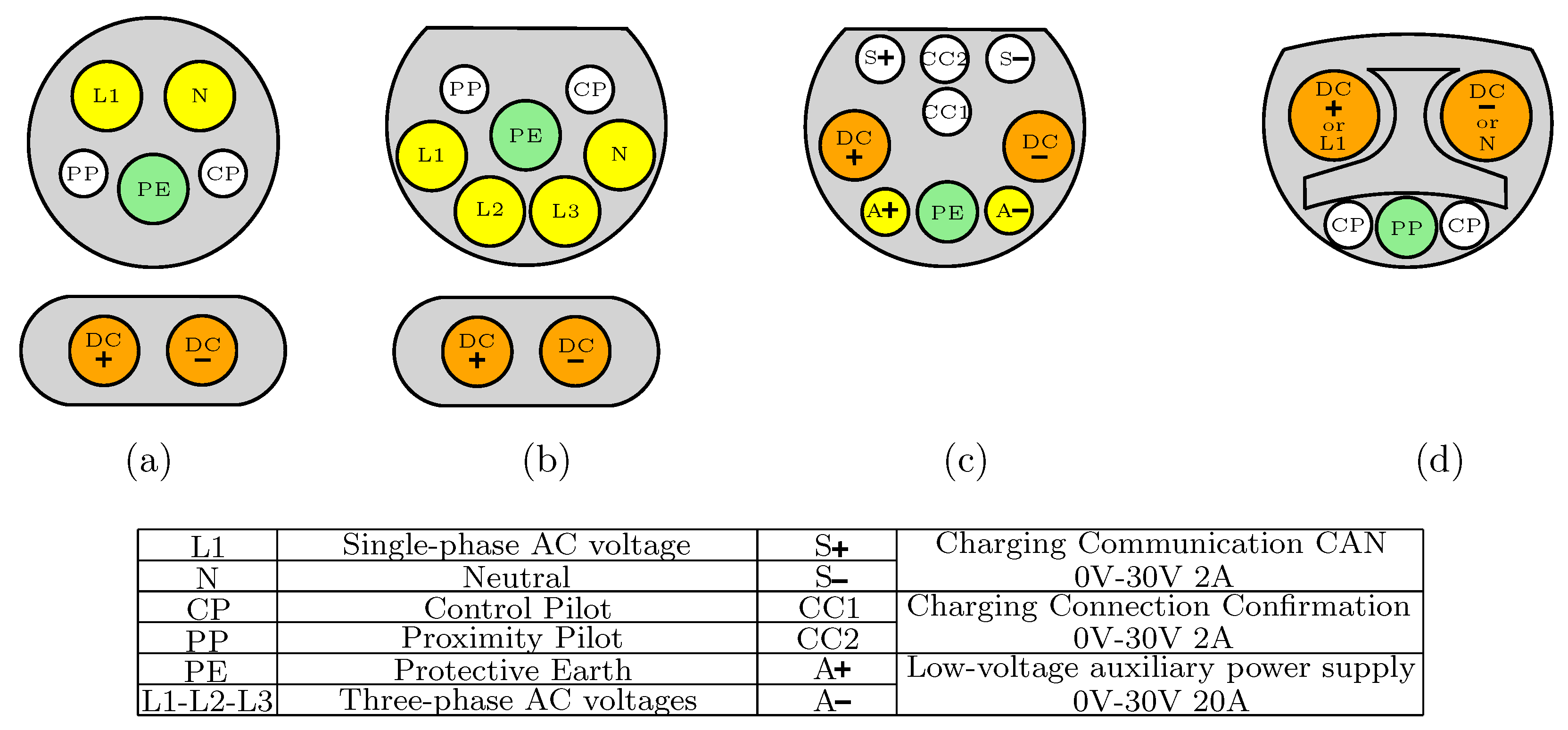
Figure 4.
The LFT-based ultra-fast charging station configurations: (a) AC-coupled; (b) DC-coupled; (c) hybrid-coupled.
Figure 4.
The LFT-based ultra-fast charging station configurations: (a) AC-coupled; (b) DC-coupled; (c) hybrid-coupled.

Figure 5.
Different types of transformers: (a) LFT; (b) SST; (c) HT.

Figure 6.
Research challenges in the DC ultra-fast charging stations.

Figure 7.
Different topologies of SST from a power conversion stages point of view: (a) single-stage (type A); (b) two-stage with LVDC link (type B); (c) two-stage with HVDC link (type C); (d) three-stage with LVDC and HVDC link (type D) [121].
Figure 7.
Different topologies of SST from a power conversion stages point of view: (a) single-stage (type A); (b) two-stage with LVDC link (type B); (c) two-stage with HVDC link (type C); (d) three-stage with LVDC and HVDC link (type D) [121].
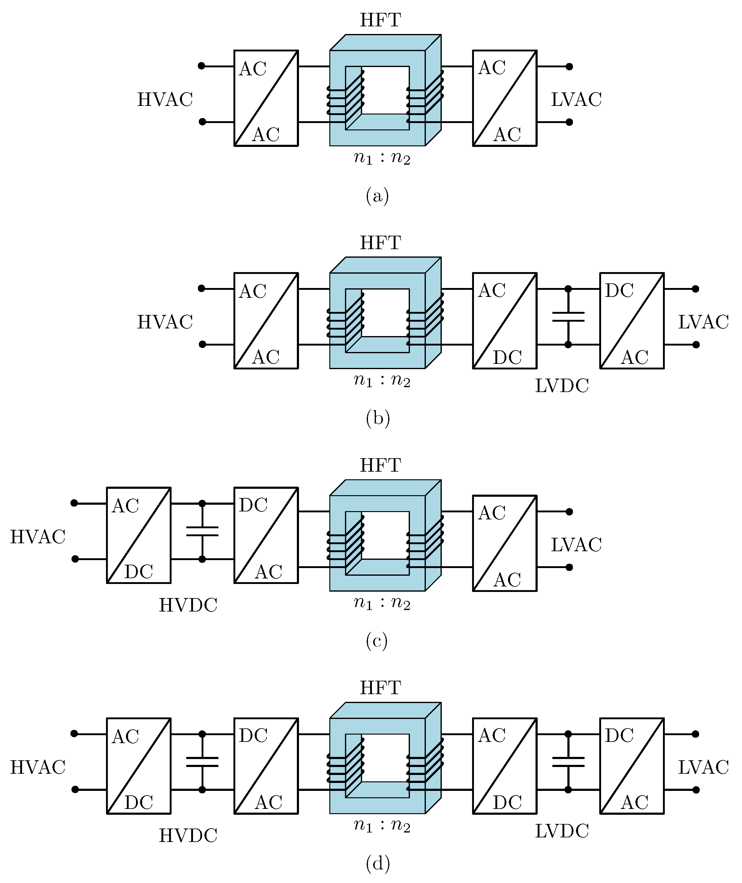
Figure 8.
Different topologies of SST from the input/output connection of power electronic converters point of view: (a) ISOP; (b) IPOS; (c) IPOP; (d) ISOS.
Figure 8.
Different topologies of SST from the input/output connection of power electronic converters point of view: (a) ISOP; (b) IPOS; (c) IPOP; (d) ISOS.

Figure 9.
Research challenges of SST.

Figure 10.
Some of the possible power electronic converters that can be used in a DC SST-based ultra-fast charging station.
Figure 10.
Some of the possible power electronic converters that can be used in a DC SST-based ultra-fast charging station.
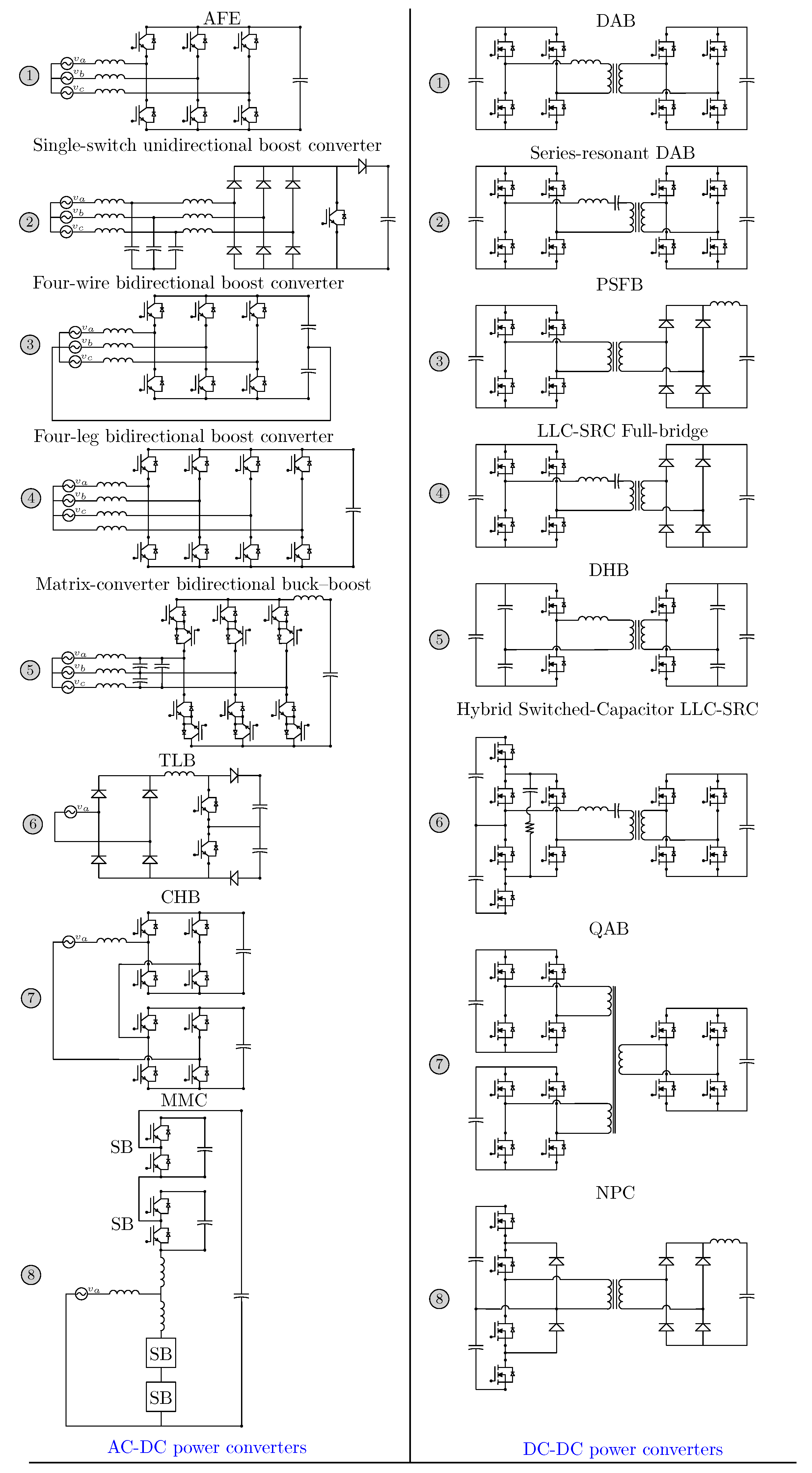
Figure 11.
Topology configuration based on input type and output ports: (a) SPSP; (b) SPMP; (c) TPSP-SPC wye connected; (d) TPSP-SPC delta connected; (e) TPMP-SPC wye connected; (f) TPMP-SPC delta connected; (g) TPSP-TPC/TPMP-TPC wye connected; (h) TPSP-TPC/TPMP-TPC delta connected.
Figure 11.
Topology configuration based on input type and output ports: (a) SPSP; (b) SPMP; (c) TPSP-SPC wye connected; (d) TPSP-SPC delta connected; (e) TPMP-SPC wye connected; (f) TPMP-SPC delta connected; (g) TPSP-TPC/TPMP-TPC wye connected; (h) TPSP-TPC/TPMP-TPC delta connected.
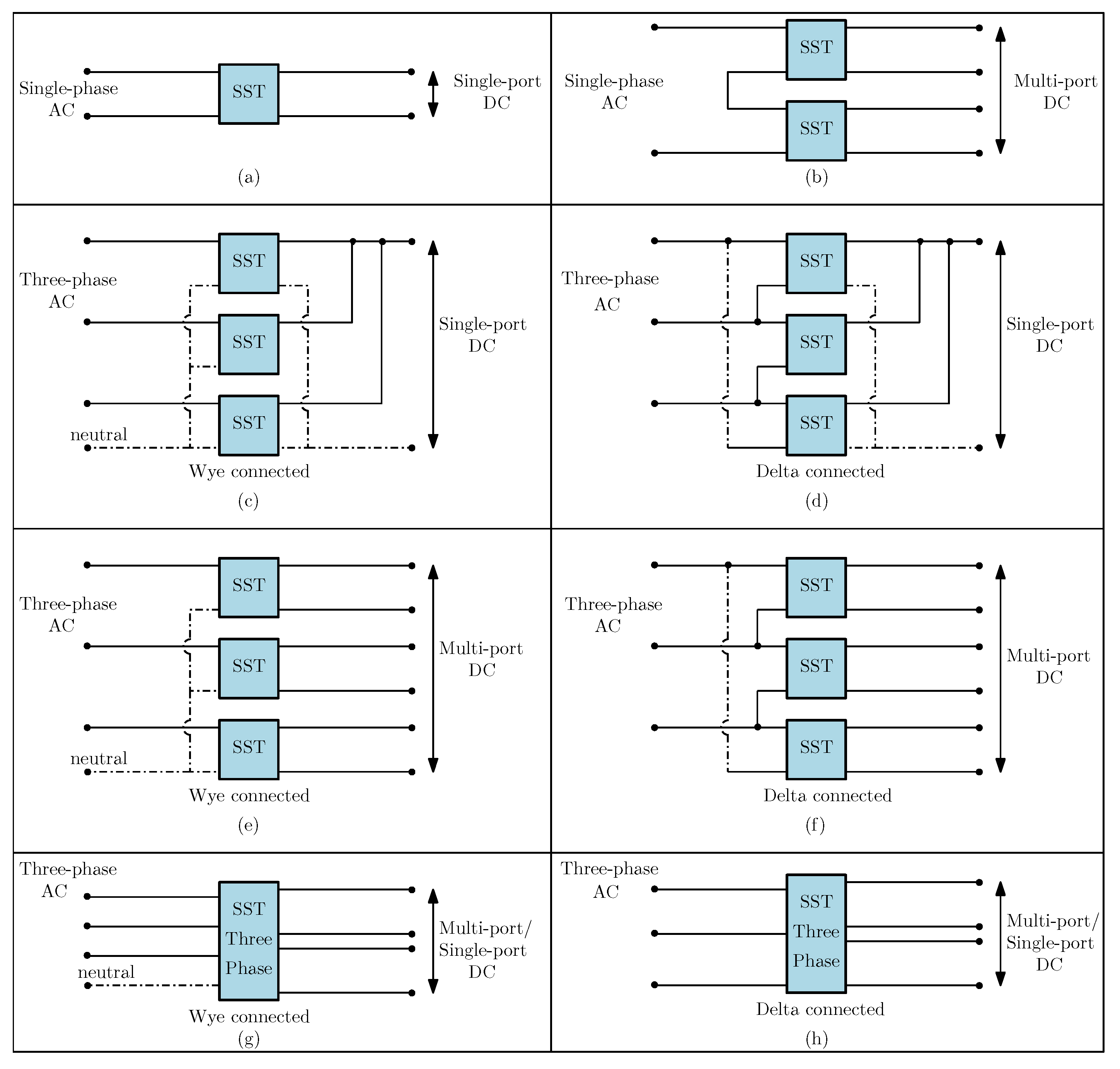
Figure 12.
Research challenges in the DC SST-based ultra-fast charging station.


Table 1.
A comparative analysis of DC LFT-based and SST-based ultra-fast charging stations.
| Ultra-Fast Charging Station | Size | Controlability | Integrarion of Large Power Plants | Fault Protection | Modularity | Reliability |
|---|---|---|---|---|---|---|
| LFT-based | Big | Limited | No | No | No | High |
| SST-based | Small | Unlimited | Yes | Yes | Yes | Medium |
Table 2.
Characteristics of battery charging connectors.
| Model | Charging Level | Voltage | Maximum Power | 100 kWh Battery Charging Time | Charger Location | Maximum Current |
|---|---|---|---|---|---|---|
| SAE J1772 | Level 1 (Slow) | 120 () | 1.44–1.92 kW | 52–69 h | on-board | 12–16 A |
| Level 2 (Slow) | 208–240 () | 5.0–19.2 kW | 5–20 h | on-board | 24–80 A | |
| Level 3 (Fast) | 50–1000 | 80 kW | 75 m | off-board | 80 A | |
| Level 4 (Ultra-fast) | 50–1000 | 400 kW | 15 m | off-board | 400 A | |
| Mennekes/EU | Level 1 | 250 () | 4–8 kW | 12.5–25 h | on-board | 16–32 A |
| Level 2 | 480 () | 13.3–22 kW | 4.5–7.5 h | on-board | 27–45 A | |
| Level 3 | 500 | 70 kW | 85 m | off-board | 140 A | |
| Level 4 | 500–1000 | 200 kW | 30 m | off-board | 200 A | |
| GB/T | Level 1 | 250 () | 7 kW | 14 h | on-board | 28 A |
| Level 2 | 400 () | 12.8 kW | 7.8 h | on-board | 32 A | |
| Level 3 | 250–950 | 60 kW | 100 m | off-board | 250–400 A | |
| Level 4 | 250-950 | 237.5 kW | 25 m | off-board | 250–400 A | |
| Tesla | Level 1 | 120/240 () | 1.9–7.7 kW | 13–52 h | on-board | 16–32 A |
| Level 2 | 208/250 () | 2.8–11.5 kW | 9–35 h | on-board | 48 A | |
| Level 3 | 300–480 | 250 kW | 24 m | off-board | 800 A | |
| Level 4 | 300–480 | 350 kW | 17 m | off-board | 800 A |
Table 3.
Battery characteristics for some of EV manufacturers.
| Car Model | Battery Type | Capacity | Voltage | Range | Fast-Charging Time | Supercharger Maximum Power |
|---|---|---|---|---|---|---|
| Tesla Model Y | Li-ion | 75 kWh | 360 V | 487 km | 31 min | 250 kW |
| Tesla Model X | Li-ion | 100 kWh | 350–375 V | 536 km | 28 min | 250 kW |
| Tesla Model 3 | Li-ion | 50–75 kWh | 350–400 V | 507 km | 31 min | 250 kW |
| Tesla Model S | Li-ion | 103 kWh | 400 V | 637 km | 27 min | 250 kW |
| Volkswagen ID.3 | Li-ion | 62 kWh | 408 V | 415 km | 38 min | 125 kW |
| Volkswagen ID.4 | Li-ion | 77 kWh | 400 V | 514 km | 38 min | 125 kW |
| Volkswagen ID.5 GTX | Li-ion | 82 kWh | 400 V | 490 km | 33 min | 135 kW |
| Renault Zoe E-Tech | Li-ion | 52 kWh | 375 V | 390 km | 78 min | 50 kW |
| Renault Megane | Li-ion | 60 kWh | 400 V | 360 km | 54 min | 130 kW |
Table 4.
Experimentally implemented SSTs in the literature for different applications.
| Application | SST Type | Power Rating (KVA) | MV (kV) | AC-DC Rectifier | DC-DC Converter | SST Efficiency | DC-link (HVDC LVDC) | High-Voltage Switches |
|---|---|---|---|---|---|---|---|---|
| Distribution network [192] | D | 1.67 | 1.15 | FB (75 kHz) | Switched-capacitor LLC-SRC (75 kHz) | 93–97% | 1.7 kV 600 V | 3 kV–12 A IGBT/1.2 kV–20 A SiC MOSFET |
| Fast charging [193] | D | 4 | 0.22 | CHB (1.05 kHz) | QAB (10 kHz) | N/A | 0.36 kV 220, 120, 48 V | N/A |
| Smart grid [194] | D | 10 | 3.6 | CHB (1.2 kHz) | DAB (3.6 kHz) | 84–92% | 5.7 kV 200 V | 6.5 kV–25 A Si IGBT |
| Distribution network [195] | D | 10 | 3.6 | FB (6 kHz) | DHB (15 kHz) | N/A | 6.1 kV 400 V | 13 kV–10 A SiC MOSFET/JBS diode |
| Distribution network [196] | D | 10 | 13.2 | 3-level PFC (20 kHz) | LLC (40 kHz) | N/A | 25 kV 500 V | 1.7 kV–5 A SiC MOSFET |
| Fast Charging [197] | D | 16 | 3.8 | TLB (20 kHz) | HB-LLC (98 kHz) | 98% | 6.2 kV 400 V | 1.2 kV–31 A SiC MOSFET |
| Wind energy [198] | D | 20 | 7.2 | CHB (1.08 kHz) | DAB (3 kHz) | 88–95% | 11.4 kV 400 V | 6.5 kV–25 A IGBT |
| Utility network [199] | D | 25 | 7.2/8 | TLB (93 kHz) | HB-LLC (93 kHz) | 97.5% | 14 kV 400 V | 1.2 kV–36 A SiC MOSFET |
| Data centers [200] | D | 25 | 3.8 | FB (48 kHz) | LLC-SRC (48 kHz) | 98–99.6% | 7 kV 400 V | 10 kV–10 A SiC MOSFET |
| Fast charging [201] | D | 25 | 2.4 | TLB (25 kHz) | NPC + diode rectifier (50 kHz) | 96.6% | 4.8 kV 400 V | 1.2 kV–55 A SiC MOSFET |
| Mobile utility support [202] | D | 100 | 4.16 | AFE (20 kHz) | DAB (10 kHz) | N/A | 7.2 kV 800 V | 10 kV–90 A Gen3 SiC MOSFET |
| Fast charging [203] | D | 400 | 13.2/4.8 | NPC (5 kHz) | LLC-SRC (100 kHz) | 96.5% | 6.4 kV 1000 V | 1.2 kV–50 A SiC MOSFET |
Table 5.
The desired performance of a SST-based DC ultra-fast charging station.
| Power Stage | Performance Criteria |
|---|---|
| AC-DC power stage | • HVDC link voltage control |
| • LVDC link voltage control | |
| • Grid current THD improvement | |
| • Grid synchronization | |
| • PFC | |
| • ZVS/ZCS | |
| • Unidirectional power flow | |
| • Bidirectional power flow | |
| • Power balancing control | |
| • Voltage balancing control | |
| • SOC balancing control | |
| • Grid ancillary services | |
| • Fault tolerant and limitation | |
| DC-DC power stage | • LVDC link voltage control |
| • ZVS/ZCS | |
| • Galvanic isolation | |
| • Unidirectional power flow | |
| • Bidirectional power flow | |
| • Power balancing control |
Table 6.
Literature control approaches of DC SST-based ultra-fast charging station.
| References | AC–DC Power Converter | AC–DC Control Approach | DC–DC Power Converter | DC–DC Control Approach |
|---|---|---|---|---|
| [193] | CHB | Cascaded PI control: • PFC • Grid synchronization • Power balancing control • Voltage balancing control • HVDC link voltage control | QAB | PI control: • DPS bidirectional power flow • Galvanic isolation • Power balancing control • LVDC link voltage control |
| [197] | TLB | Digital PI control: • PFC • Grid synchronization • Voltage balancing control • HVDC link voltage control • Grid current THD improvement | HB-LLC | Digital open-loop control: • Unidirectional power flow • Galvanic isolation • LVDC link voltage control • ZVS |
| [223] | CHB | Cascaded PI control: • PFC • Grid synchronization • Power balancing control • Voltage balancing control • SOC balancing control • HVDC link voltage control | DHB | Digital PI+PR control: • Bidirectional power flow • Galvanic isolation • LVDC link voltage control • ZVS |
| [247] | CHB | PI control: • Grid ancillary services • HVDC link voltage control | DAB | PI control: • Bidirectional power flow • Galvanic isolation • LVDC link voltage control • ZVS |
| [248] | CHB | PI control: • PFC • Grid synchronization • Power balancing control • HVDC link voltage control | DAB | Cascaded PI control: • DPS bidirectional power flow • Galvanic isolation • LVDC link voltage control |
| [249] | VR | Multi-loop PI and hysteresis current control: • PFC • Grid synchronization • Voltage balancing control • HVDC link voltage control | DAB | Cascaded PI control: • SPS bidirectional power flow • Galvanic isolation • LVDC link voltage control |
| [250] | TLB | Multi-loop PI and predictive current control: • PFC • Grid synchronization • Voltage balancing control • HVDC link voltage control | DAB-ANPC | PR control: • TPS bidirectional power flow • Galvanic isolation • LVDC link voltage control • ZVS |
| [251] | TLT | Digital multi-loop PI control: • PFC • Grid synchronization • Voltage balancing control • HVDC link voltage control | N/A | N/A |
| [252] | CHB | Multi-loop PI and predictive power control: • Fault tolerant and limitation • Voltage balancing control • LVDC link voltage control | DAB | PI control: • SPS bidirectional power flow • Galvanic isolation • ZVS |
| [253] | MCB | PI control: • Voltage balancing control • HVDC link voltage control | NPC | PI control: • Power flow • Galvanic isolation • LVDC link voltage control |
Publisher’s Note: MDPI stays neutral with regard to jurisdictional claims in published maps and institutional affiliations. |
© 2022 by the authors. Licensee MDPI, Basel, Switzerland. This article is an open access article distributed under the terms and conditions of the Creative Commons Attribution (CC BY) license (https://creativecommons.org/licenses/by/4.0/).
Share and Cite
MDPI and ACS Style
Valedsaravi, S.; El Aroudi, A.; Martínez-Salamero, L. Review of Solid-State Transformer Applications on Electric Vehicle DC Ultra-Fast Charging Station. Energies 2022, 15, 5602. https://doi.org/10.3390/en15155602
AMA Style
Valedsaravi S, El Aroudi A, Martínez-Salamero L. Review of Solid-State Transformer Applications on Electric Vehicle DC Ultra-Fast Charging Station. Energies. 2022; 15(15):5602. https://doi.org/10.3390/en15155602
Chicago/Turabian StyleValedsaravi, Seyedamin, Abdelali El Aroudi, and Luis Martínez-Salamero. 2022. "Review of Solid-State Transformer Applications on Electric Vehicle DC Ultra-Fast Charging Station" Energies 15, no. 15: 5602. https://doi.org/10.3390/en15155602
Note that from the first issue of 2016, this journal uses article numbers instead of page numbers. See further details here.