


Modular Multilevel Converter for a Linear Generator for Wave Energy Converter

Abstract
:1. Introduction
2. System Model
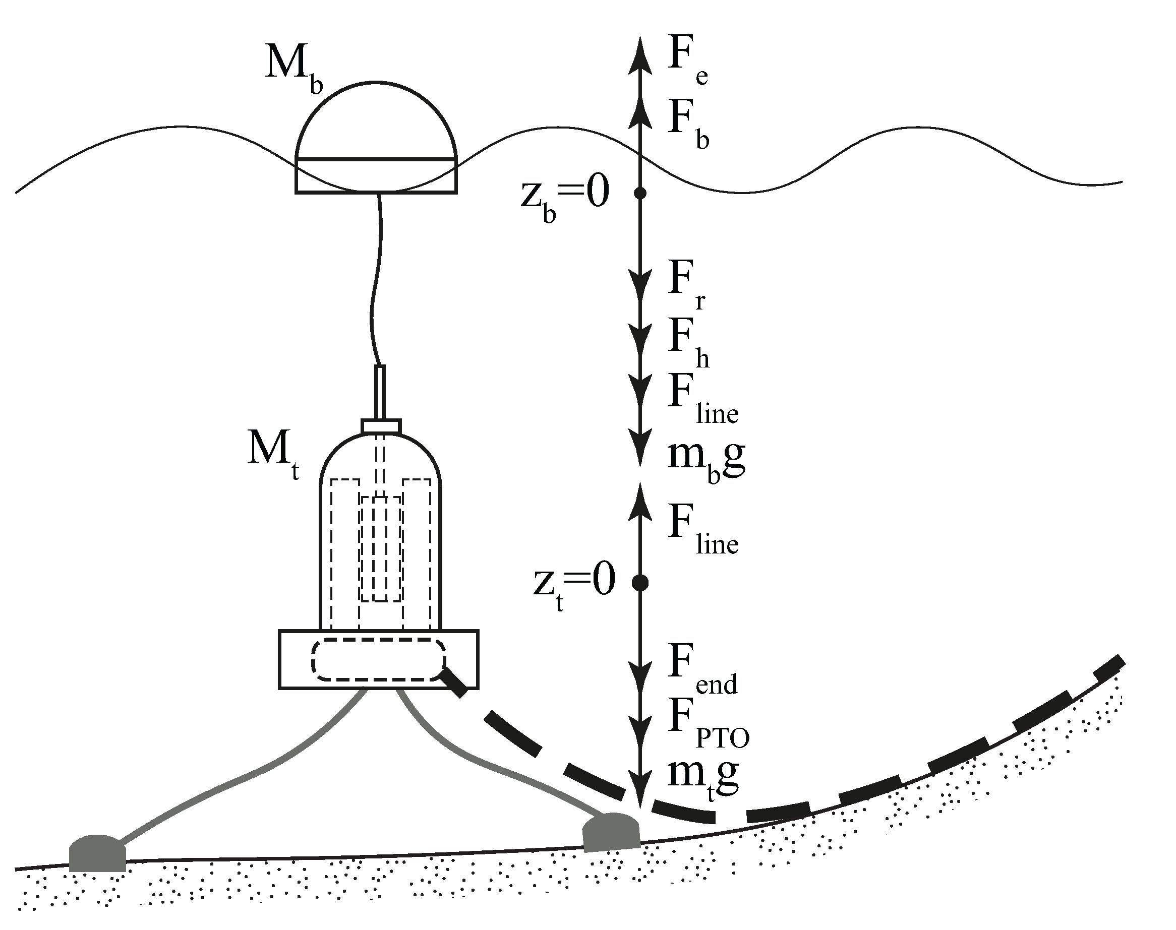
2.1. Wave–Buoy Interaction
2.2. WEC Equation of Motion
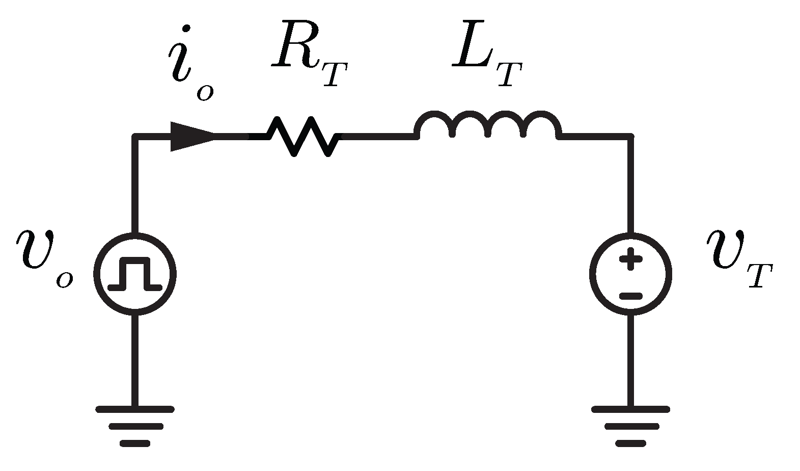
2.3. Power Take-Off
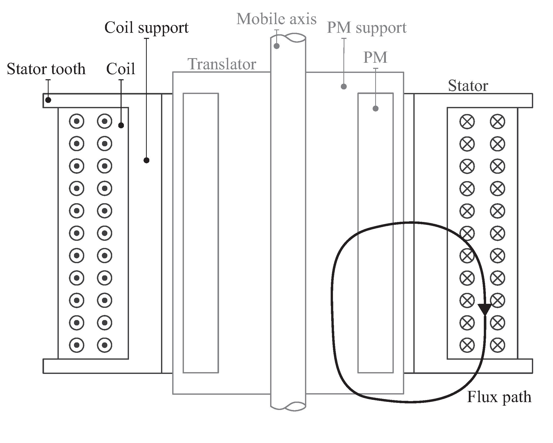
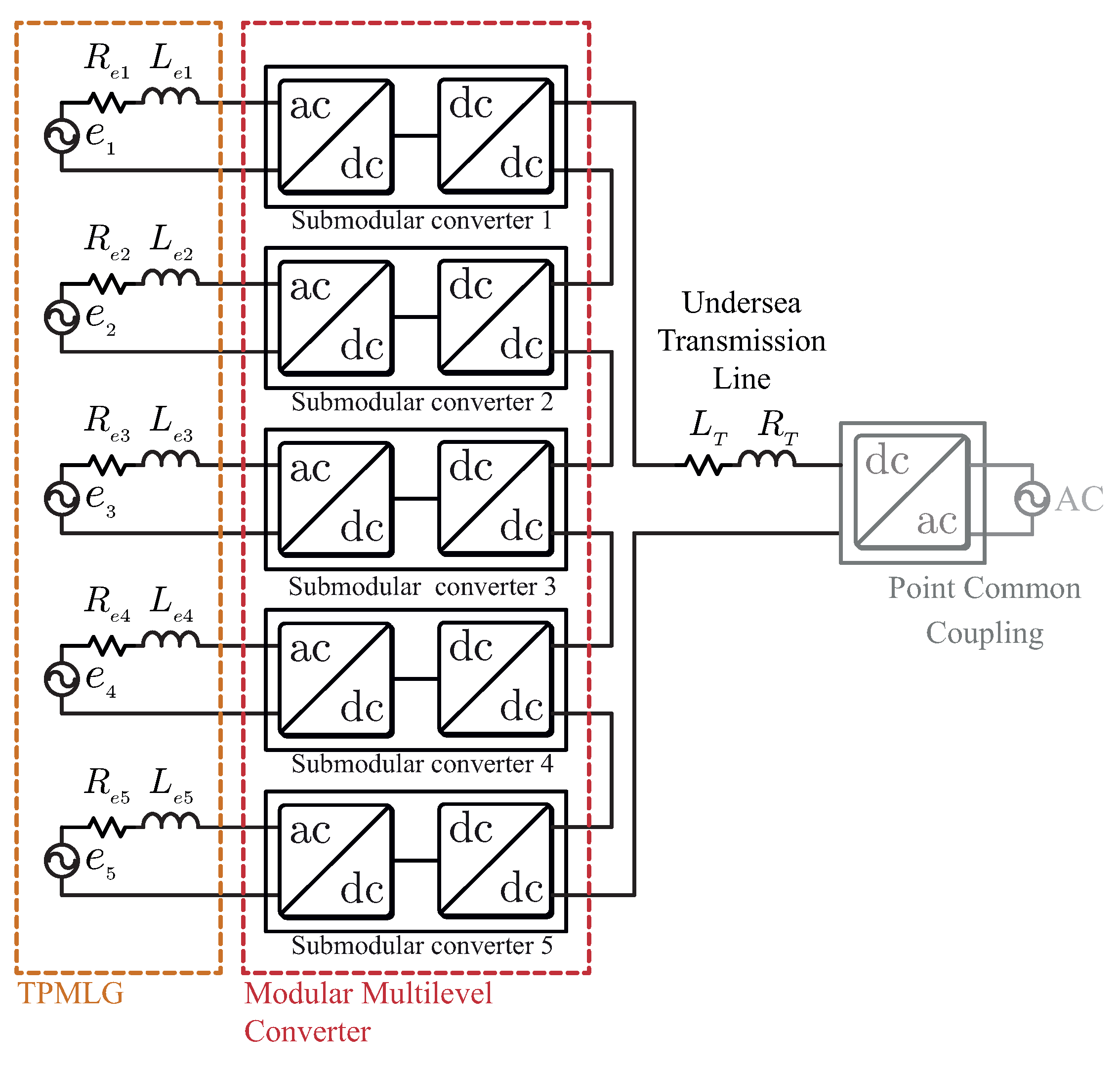
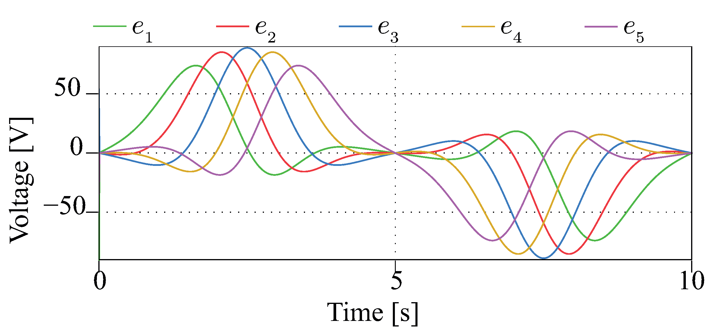
3. MMC Description
4. Control Strategy
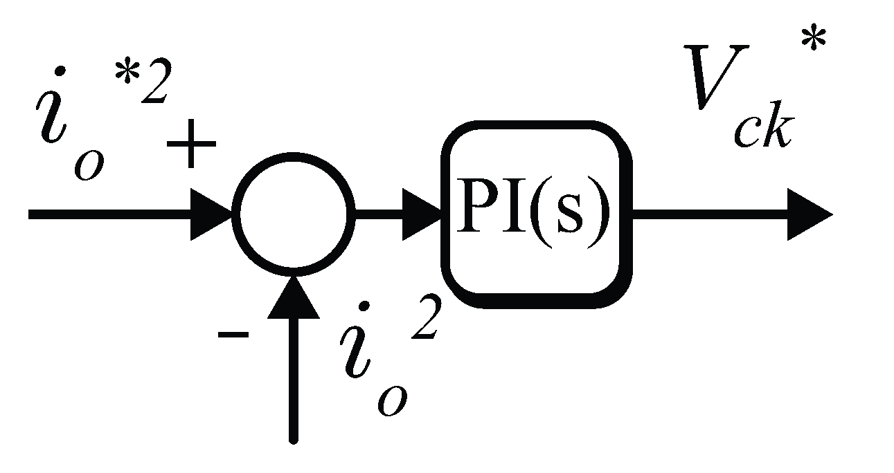
4.1. Harvesting Control
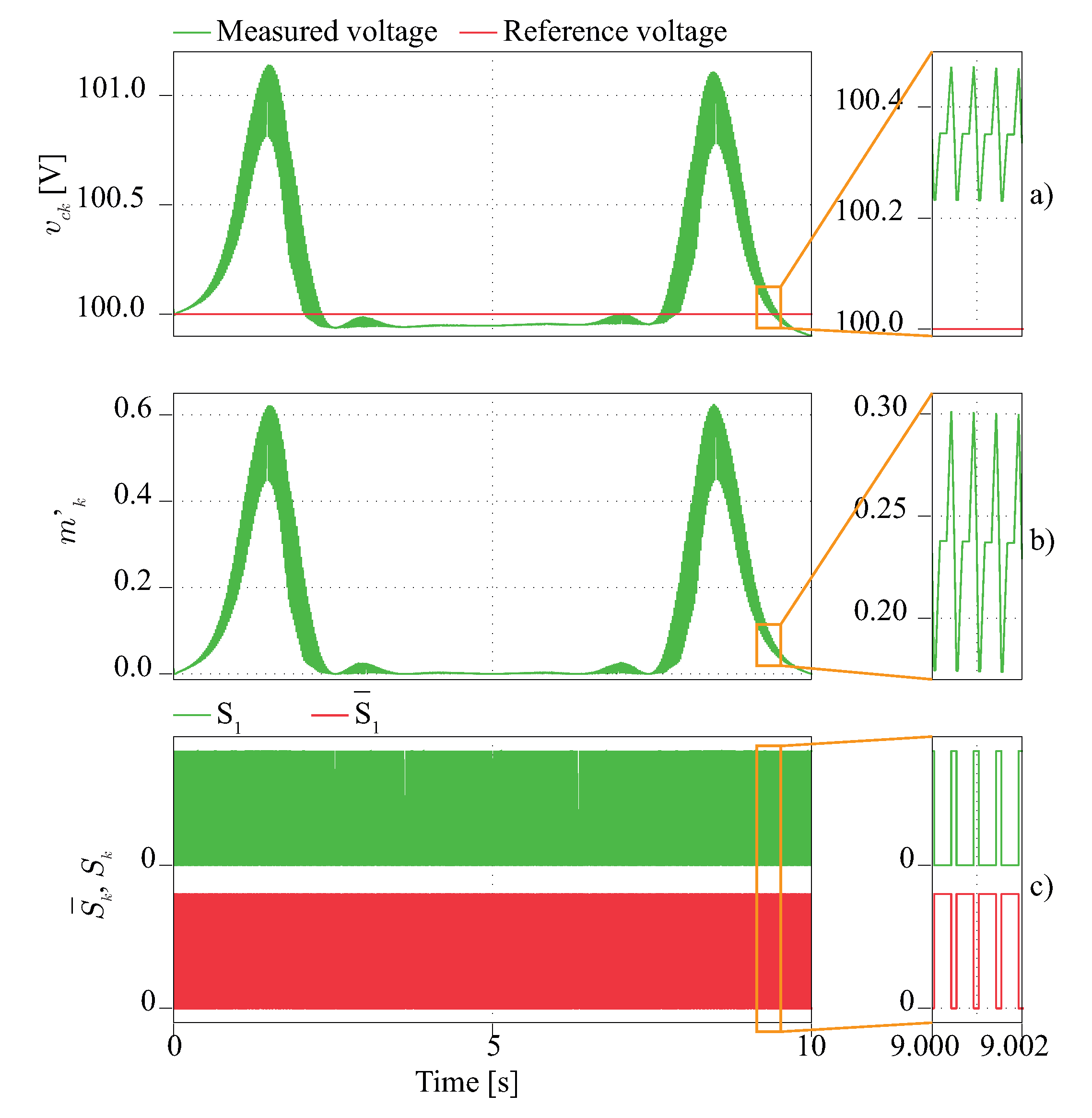
4.2. DC-Link Voltage Control
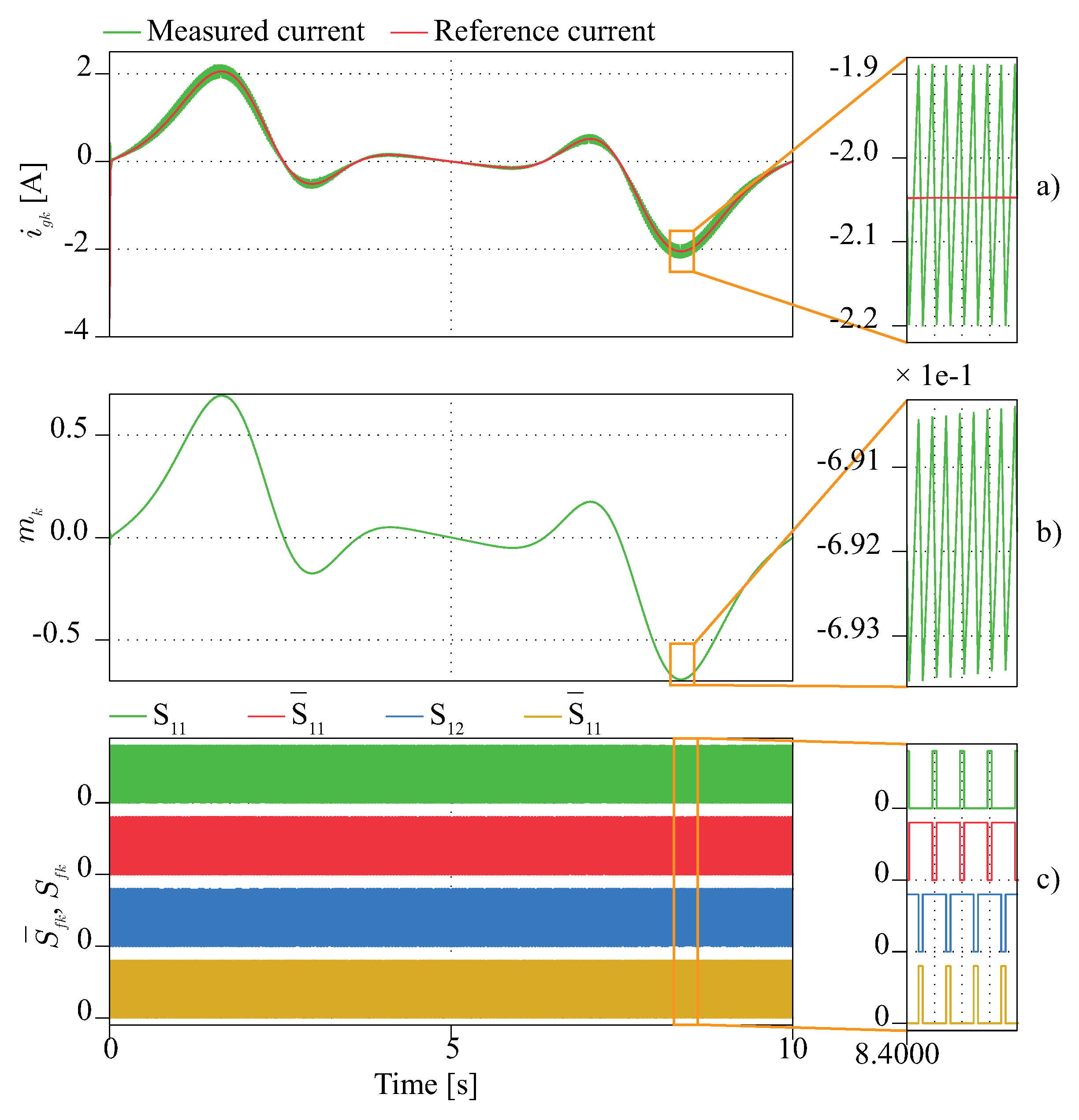
4.3. Current Control
5. Conclusions
Author Contributions
Funding
Institutional Review Board Statement
Informed Consent Statement
Conflicts of Interest
References
- Ivanova, I.; Agren, O.; Bernhoff, H.; Leijon, M. Simulation of wave-energy converter with octagonal linear generator. IEEE J. Ocean. Eng. 2005, 30, 619–629. [Google Scholar] [CrossRef]
- Gao, Y.; Shen, Z.; Tan, F.; Yue, G.; Liu, R.; Wang, Z.; Qu, S.; Wang, Z.; Zhang, W. Novel benzo[1,2-b:4,5-b’]difuran-based copolymer enables efficient polymer solar cells with small energy loss and high VOC. Nano Energy 2020, 76, 104964. [Google Scholar] [CrossRef]
- Gao, Y.; Cui, M.; Qu, S.; Zhao, H.; Shen, Z.; Tan, F.; Dong, Y.; Qin, C.; Wang, Z.; Zhang, W.; et al. Efficient Organic Solar Cells Enabled by Simple Non-Fused Electron Donors with Low Synthetic Complexity. Small 2022, 18, 2104623. [Google Scholar] [CrossRef] [PubMed]
- Huang, J.; He, S.; Zhang, W.; Saparbaev, A.; Wang, Y.; Gao, Y.; Shang, L.; Dong, G.; Nurumbetova, L.; Yue, G.; et al. Efficient and Stable All-Inorganic CsPbIBr2 Perovskite Solar Cells Enabled by Dynamic Vacuum-Assisted Low-Temperature Engineering. Solar RRL 2022, 6, 2100839. [Google Scholar] [CrossRef]
- Nakamura, M.; Yamaguchi, K.; Kimoto, Y.; Yasaki, Y.; Kato, T.; Sugimoto, H. Cd-Free Cu(In,Ga)(Se,S)2 Thin-Film Solar Cell With Record Efficiency of 23.35. IEEE J. Photovolt. 2019, 9, 1863–1867. [Google Scholar] [CrossRef]
- International Renewable Energy Agency (IRENA). Renewable Capacity Statistics 2021; IRENA: Masdar, United Arab Emirates, 2021. [Google Scholar]
- REN21. Renewables 2021 Global Status Report. In Technical Report on Renewable Energy Policy Network for the 21st Century; REN21 Secretariat: Paris, France, 2021. [Google Scholar]
- Edenhofer, O.; Pichs-Madruga, R.; Sokona, Y.; Seyboth, K.; Kadner, S.; Zwickel, T.; Eickemeier, P.; Hansen, G.; Schlömer, S.; von Stechow, C.; et al. Renewable Energy Sources and Climate Change Mitigation: Special Report of the Intergovernmental Panel on Climate Change; Cambridge University Press: Cambridge, MA, USA, 2011. [Google Scholar]
- Gunn, K.; Stock-Williams, C. Quantifying the global wave power resource. Renew. Energy 2012, 44, 296–304. [Google Scholar] [CrossRef]
- Melikoglu, M. Current status and future of ocean energy sources: A global review. Ocean Eng. 2018, 148, 563–573. [Google Scholar] [CrossRef]
- European Commission. Study on Lessons for Ocean Energy Development; Technical Report; European Commission (EC): Brussels, Belgium, 2017. [Google Scholar]
- Drew, B.; Plummer, A.R.; Sahinkaya, M.N. A Review of Wave Energy Converter Technology; Sage Publications: Thousand Oaks, CA, USA, 2009. [Google Scholar]
- Czech, B.; Bauer, P. Wave Energy Converter Concepts: Design Challenges and Classification. IEEE Ind. Electron. Mag. 2012, 6, 4–16. [Google Scholar] [CrossRef]
- Pecher, A.; Kofoed, J.P. Handbook of Ocean Wave Energy; Springer: London, UK, 2017. [Google Scholar]
- Wave Devices; European Marine Energy Centre (EMEC): Stromness, UK, 2018.
- Aamir Hussain Memon, B.; Ibrahim, T.; Perumal, N. Portable and pico-scale linear generator for wave energy conversion. In Proceedings of the 2014 5th International Conference on Intelligent and Advanced Systems (ICIAS), Kuala Lumpur, Malaysia, 3–5 June 2014; pp. 1–4. [Google Scholar]
- Abdalla, I.I.; Ibrahim, T.; Nor, N.M. Analysis of Tubular Linear Motors for Different Shapes of Magnets. IEEE Access 2018, 6, 10297–10310. [Google Scholar] [CrossRef]
- Jiabin, W.; Jewell, G.W.; Howe, D. A general framework for the analysis and design of tubular linear permanent magnet machines. IEEE Trans. Magn. 1999, 35, 1986–2000. [Google Scholar] [CrossRef] [Green Version]
- Curcic, M.; Quaicoe, J.E.; Bachmayer, R. A novel double-sided linear generator for wave energy conversion. In Proceedings of the OCEANS 2015, Genova, Italy, 8 June 2015; pp. 1–7. [Google Scholar]
- Mesantono, L.D.; Danang Wijaya, F.; Haryono, T. Comparison of linear flux permanent magnet generator topologies by using FEMM 2D. In Proceedings of the 2016 8th International Conference on Information Technology and Electrical Engineering (ICITEE), Yogyakarta, Indonesia, 5–6 October 2016; pp. 1–5. [Google Scholar]
- Farrok, O.; Islam, M.R.; Islam Sheikh, M.R.; Guo, Y.; Zhu, J.; Lei, G. Oceanic Wave Energy Conversion by a Novel Permanent Magnet Linear Generator Capable of Preventing Demagnetization. IEEE Trans. Ind. Appl. 2018, 54, 6005–6014. [Google Scholar] [CrossRef]
- Páez, J.D.; Frey, D.; Maneiro, J.; Bacha, S.; Dworakowski, P. Overview of DC–DC Converters Dedicated to HVdc Grids. IEEE Trans. Power Deliv. 2019, 34, 119–128. [Google Scholar] [CrossRef]
- Han, X.; Sima, W.; Yang, M.; Li, L.; Yuan, T.; Si, Y. Transient Characteristics Under Ground and Short-Circuit Faults in a ±500kV MMC-Based HVDC System With Hybrid DC Circuit Breakers. IEEE Trans. Power Deliv. 2018, 33, 1378–1387. [Google Scholar] [CrossRef]
- You, H.; Cai, X. A Three-Level Modular DC/DC Converter Applied in High Voltage DC Grid. IEEE Access 2018, 6, 25448–25462. [Google Scholar] [CrossRef]
- Kish, G.J.; Ranjram, M.; Lehn, P.W. A Modular Multilevel DC/DC Converter With Fault Blocking Capability for HVDC Interconnects. IEEE Trans. Power Electron. 2015, 30, 148–162. [Google Scholar] [CrossRef]
- Binh, P.C.; Tri, N.M.; Dung, D.T.; Ahn, K.K.; Kim, S.; Koo, W. Analysis, design and experiment investigation of a novel wave energy converter. IET Gener. Transm. Distrib. 2016, 10, 460–469. [Google Scholar] [CrossRef]
- Falnes, J.; Kurniawan, A. Ocean Waves and Oscillating Systems: Linear Interactions Including Wave-Energy Extraction; Cambridge University Press: Cambridge, MA, USA, 2020; Volume 8. [Google Scholar]
- Brooke, J. Wave Energy Conversion; Elsevier: Amsterdam, The Netherlands, 2003; Volume 6. [Google Scholar]
- Goda, Y. Random Seas and Design of Maritime Structures; World Scientific Publishing Company: Singapore, 2010; Volume 33. [Google Scholar]
- Hayt, W.H.; Buck, J.A. Engineering Electromagnetics, 8th ed.; McGraw-Hill: New York, NY, USA, 2012; p. 593. [Google Scholar]
- Zapata, H.M.; Cabrera, F.A.; Perez, M.A.; Silva, C.A.; Jara, W. Model of a permanent magnet linear generator. In Proceedings of the IECON 2019-45th Annual Conference of the IEEE Industrial Electronics Society, Lisbon, Portugal, 14–17 October 2019; Volume 1, pp. 6992–6997. [Google Scholar]
- Gieras, J.F.; Piech, Z.J.; Tomczuk, B.Z. Linear Synchronous Motors, 2nd ed.; CRC Press: Boca Raton, FL, USA, 2012; p. 520. [Google Scholar]
- Zhang, J.; Yu, H.; Chen, Q.; Hu, M.; Huang, L.; Liu, Q. Design and Experimental Analysis of AC Linear Generator with Halbach PM Arrays for Direct-Drive Wave Energy Conversion. IEEE Trans. Appl. Supercond. 2014, 24, 3–6. [Google Scholar] [CrossRef]
- Echeverría, J.; Kouro, S.; Pérez, M.; Abu-rub, H. Multi-modular cascaded DC-DC converter for HVDC grid connection of large-scale photovoltaic power systems. In Proceedings of the IECON 2013-39th Annual Conference of the IEEE Industrial Electronics Society, Vienna, Austria, 10–13 November 2013; pp. 6999–7005. [Google Scholar] [CrossRef]


Publisher’s Note: MDPI stays neutral with regard to jurisdictional claims in published maps and institutional affiliations. |
© 2022 by the authors. Licensee MDPI, Basel, Switzerland. This article is an open access article distributed under the terms and conditions of the Creative Commons Attribution (CC BY) license (https://creativecommons.org/licenses/by/4.0/).
Share and Cite
Zapata, H.M.; Pérez, M.A. Modular Multilevel Converter for a Linear Generator for Wave Energy Converter. Energies 2022, 15, 6346. https://doi.org/10.3390/en15176346
Zapata HM, Pérez MA. Modular Multilevel Converter for a Linear Generator for Wave Energy Converter. Energies. 2022; 15(17):6346. https://doi.org/10.3390/en15176346
Chicago/Turabian StyleZapata, Henry M., and Marcelo A. Pérez. 2022. "Modular Multilevel Converter for a Linear Generator for Wave Energy Converter" Energies 15, no. 17: 6346. https://doi.org/10.3390/en15176346
APA StyleZapata, H. M., & Pérez, M. A. (2022). Modular Multilevel Converter for a Linear Generator for Wave Energy Converter. Energies, 15(17), 6346. https://doi.org/10.3390/en15176346