Abstract
Nowadays, the influences of the communication structure on the frequency regulation performance in a multi-area power system are barely studied. In this paper, a decentralized frequency regulation method for a multi-area power system considering optimization of communication structure is presented, and the influence of the communication structure on the frequency regulation performance is studied. Firstly, the communication network model is described and the multi-area power system model considering communication structure is presented. Then, the optimization model of communication structure during a decentralized frequency regulation process is constructed. This model aims to speed up the convergence speed of the control together with ensuring the high algebraic connectivity of the communication structure. Quantum binary particle swarm optimization (QB-PSO) algorithm is introduced to solve this model and, based on this, the communication structure optimization process and frequency regulation method are proposed. The simulation results show that the proposed method could greatly improve the frequency control efficiency through the optimization of the communication structure.
1. Introduction
Frequency regulation of power systems has become one of the main challenges to develop smart grids consisting of a large amount of renewable energies, such as wind and solar energy [1,2,3,4,5,6,7,8]. Generally, a large-scale power system is made up of several subsystems. Each subsystem uses tie-lines to connect with its neighbors. In a multi-area power system, the exchange power between areas makes frequency regulation more complicated, and the frequency control for multi-area power systems has attracted great attention in recent years [9].
The PI control might be firstly investigated to regulate the frequency of a power system. However, traditional PI controllers with fixed structure and parameters are usually designed for single condition [10]. The power system elements are often nonlinear and traditional PI controllers may not perform well in other conditions, which limits their scope of application.
Except for PI control, robust control [11,12], fuzzy control [9,13,14], variable structure control [15,16], disturbance rejection control [17], model-predictive control [18] and artificial intelligence-based control [19,20] are reported to be effective in dealing with the frequency regulation problems of power systems. For example, in [9] a frequency control method for multi-area power systems is developed based on the direct-indirect adaptive fuzzy control technique and the results show the superiority of the proposed method over a classical PID controller and a type-2 fuzzy controller. In [15], an adaptive supplementary control scheme for power system frequency regulation is proposed. This control scheme models the disturbances and parameter uncertainties into the frequency regulation model, and the comparative results illustrate the favorable performance of the proposed adaptive approach for the frequency regulation under load disturbances and parameter uncertainties. In [17], in order to control the frequency of the multi-area power system, a two-layer active disturbance rejection control method is proposed. Not only the effects of random load variation and parameter uncertainty are eliminated, but also high dynamic performance is guaranteed. In [19], a data-driven cooperative model for frequency control of multi-area power systems is presented. Simulation results show that the control errors of random frequency variations caused by load and renewable power fluctuations greatly decrease by applying the presented method.
There is also another way to classify the frequency regulation method for most of the control schemes, i.e., centralized schemes and decentralized schemes. Generally speaking, because only the local area state information is used to suppress the frequency deviation in a decentralized scheme, the decentralized scheme is more practical than the centralized one [21,22]. In [21], based on a decentralized control structure, in order to regulate the frequency of a multi-area power system with uncertainties, a frequency controller is designed and tested in a three-area power system. The simulation results show the effectiveness of the proposed decentralized sliding mode control scheme. In [23], in the global system, each local area network is covered with states representing interconnections with other local area networks, and a decentralized control scheme is designed as function of the local area state variables and those resulting from the overlapped states, which represent an approximation of the interconnection variables. In [24], by applying a multi-objective optimization-based gain-tuning method through considering frequency nadir, time response, steady-state error, total load shed and aggregated disutility of controllable loads subject to power balance over the network, an improved optimal frequency control is introduced. Simulation results indicate that power system frequency regulation can be improved by enabling a multi-objective optimization-based gain-tuning procedure. In [25], in an islanded microgrid containing multiple virtual synchronous generators, a novel decentralized control scheme for non-error frequency regulation without intercommunication is presented, and results show that among virtual synchronous generators the proposed control strategy can achieve frequency restoration and accurate proportional power sharing simultaneously without intercommunication.
Although there are advantages to the decentralized frequency regulation scheme in some respects, one problem that few researchers have focused on is the influences of the communication structure on the frequency regulation performance in a multi-area power system. Under the decentralized scheme, one area can only get the state information of its some local areas. The communication relationship of different areas during frequency regulation is obviously determined by the communication structure, and the control performance is also influenced by this structure. In [26], the researchers investigate the consensus convergence speed in different structures of small-world networks under a decentralized control scheme. The authors in [27] focus on the convergence behavior of discrete-time consensus protocols over large-scale networks with uniformly random deployment. The work in [26,27] verifies the obvious influences of the network structure on the decentralized control.
Inspired by these results, in this paper the main contributions are summarized as follows:
(1) A binary optimization model is proposed to solve the communication structure optimization problem.
(2) The QB-PSO algorithm is introduced to solve the optimization model.
(3) The influence of the communication structure on the frequency regulation performance is studied.
The rest of the paper is organized as follows: In Section 2, the model of the communication network and multi-area power system is described. The frequency regulation method considering optimization of communication structure is presented in Section 3. Performance test results are shown in Section 4. Conclusions are presented in Section 5.
2. Modeling for Communication Network and Multi-Area Power System
2.1. Communication Network Model
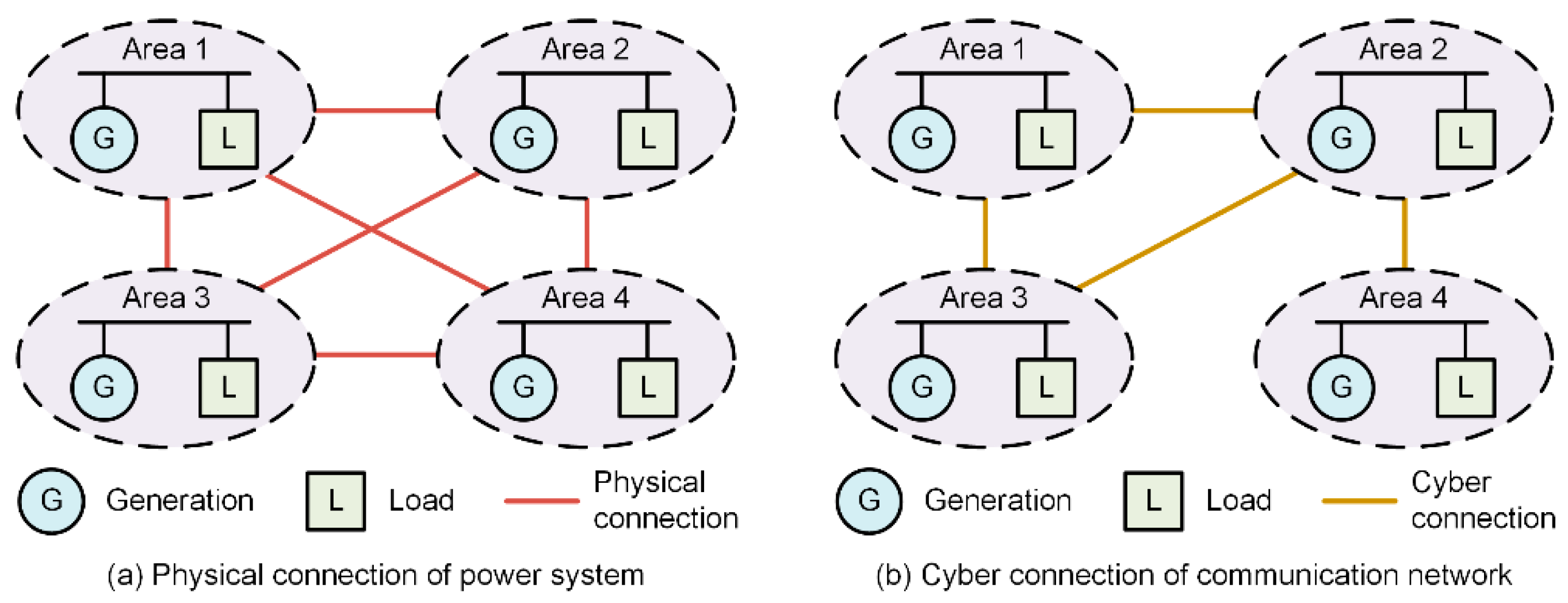
We use Gp = (N, Ep) and Gc = (N, Ec) to describe the power system and the communication network, respectively, where N = {1,…,n} is the set of power system areas, Ep ⊂ N × N is the set of physical transmission lines among different power system areas, Ec ⊂ N × N is the set of communication channels among different power system areas. Recent studies assume Ec = Ep, which is a special case of the model considered here. However, in this paper, we do not require that Gc equal to Gp. In other words, the cyber network may contain communication channels connecting non-neighboring buses in the physical network and physical neighbors may not be able to communicate. Here, the physical links among different power system areas are fixed, but the cyber links among areas are variables to be optimized. Figure 1 shows the relationship of power system and communication network.
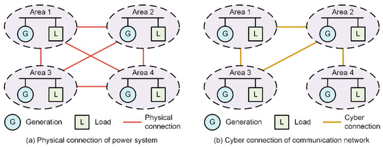
Figure 1.
Relationship of power system and communication network.
Supposing that the communication network has N nodes (corresponding to N power system areas) and m communication links, then its line-node incidence matrix Ac, with the size of m × N, can be written as
if the t-th link is from node i to node j.
The Laplacian matrix of the communication network Lc can be obtained as with
with i,j = 1,2,…,N.
The second smallest eigenvalue of the Laplacian matrix is called the algebraic connectivity. is an important concept of Laplacian matrix which reflects the connectivity and speed of information exchange of the network. As the characteristic of Laplacian matrix, its smallest eigenvalue is always zero, i.e., . If and only if the network is a connected graph, the eigenvalue is positive. If the algebraic connectivity is close to 0, the network is almost a disconnected graph. Otherwise, if tends to be 1, the network tends to be a fully connected graph.
2.2. Multi-Area Power System Model Considering Communication Structure
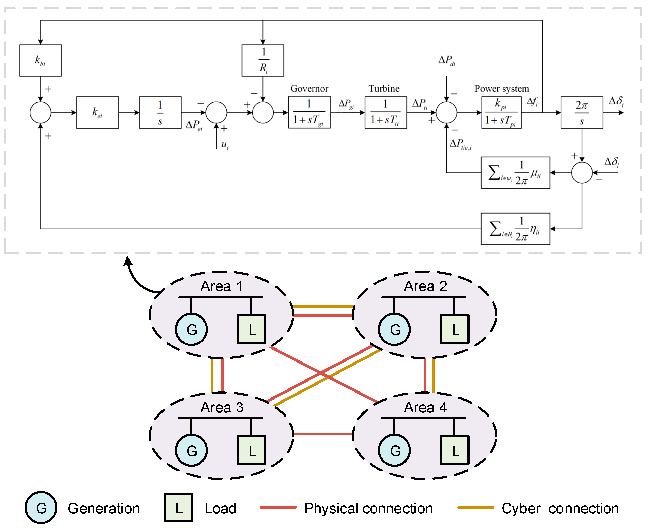
The dynamic equations of the i-th area of a multi-area power system are as follows:
where is the frequency deviation, is the power output deviation, is the governor valve position deviation, is the integral control deviation, is the rotor angle deviation, is the control vector, is the vector of load disturbance, is the power system gain, is the integral control gain, is the frequency bias factor, is the speed regulation coefficient, is the time constant of power system, is the time constant of turbine, is the time constant of governor, is the physical neighbors of the i-th area (the areas set which have links with the i-th area through transmission lines), is the cyber neighbors of the i-th area (the areas set which have links with the i-th area through communication lines), is the physical interconnection gain between the i-th area and the l-th area, and is the cyber interconnection gain between the i-th area and the l-th area.
The above differential equations can be compacted into a matrix format as
where
Further, the state-space of the whole power system containing N areas can be written as Equation (15), where the matrix C is integrated into matrix A
where
In Equations (16)–(19), diag(yi) is the diagonal matrix with yi as the diagonal elements; row(yi) is the row vector with yi as the row elements. The expressions of and are
where column(yi) is the column vector with yi as the column elements, is the entry of the Laplacian matrix of the power system Lp in the ith row and jth column, and is the entry of the Laplacian matrix of the communication network Lc in the ith row and jth column.
3. Frequency Regulation Method Considering Optimization of Communication Structure
3.1. Optimization Model of Communication Structure
Firstly, the communication network should be a connected graph. Thus, we need to ensure that . In addition, considering that is the measure of speed of convergence (or performance) of the consensus algorithm, and a network with a relatively high algebraic connectivity is necessarily robust to failures, we hope that is large enough. Thus, the first objective for the optimization model of communication structure is
Secondly, the eigenvalues of the matrix A reflect the dynamic behaviors of the whole system. If there exist eigenvalues with positive real part, the system is unstable. Thus, we need to ensure that the real part of all eigenvalues should be negative. In addition, considering that the larger distance between the eigenvalues and the imaginary axis would bring faster the convergence speed of the system, we hope that the maximum value of all eigenvalues should be as small as possible. Thus, the second objective for the optimization model of communication structure is
where is the eigenvalues of matrix A.
The second objective can also be represented as
The constraints include
where are the elements in the top right of the , as shown in Figure 2. is the number of the communication links.
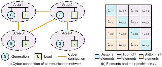
Figure 2.
Communication network and the corresponding Laplacian matrix.
In the paper, we apply the consensus algorithm in our frequency regulation method. In order to ensure the consensus algorithm converges to a steady state, we need to ensure that the communication network is a connected graph, which equals to . We can draw a conclusion that as long as condition is met, the method works. Therefore, we set a constraint that in Equation (25), which reflects the lower threshold of . Since larger means better performance (faster speed of convergence) of the consensus algorithm, the upper threshold of does not exist.
In the opitimization model, we use penalty function to deal with the constraints. For example, we convert into a penalty function to guarantee that the of the output Laplacian matrix is positive.
The variables to be optimized are , which is a N × N matrix. The non-diagonal elements in are either 0 or −1, and the diagonal elements in are the opposite number of the sum of the elements in the corresponding row. Also, is a symmetrical matrix. Thus, we just need to optimize the top right of the , and the other parts can be automatically filled.
3.2. QB-PSO Algorithm
The optimization model in Section 3.1 belongs to the binary optimization problem. This paper uses QB-PSO to solve the problem of communication structure optimization. Based on the traditional particle swarm optimization algorithm, QB-PSO introduces the principles of quantum computing. QB-PSO avoids the speed update process by using a Q-bit individual to define the probabilistic representation of particles, which improves the performance of the traditional binary particle swarm optimization model (B-PSO).
In the QB-PSO, the state of each element in a particle takes a value of 0 or 1 by the probability of or . In other words, the quantum computing takes the place of the speed update process in the traditional B-PSO. Therefore, an inertia weight factor (i.e., ω) and two acceleration coefficients (i.e., c1 and c2) can be removed, and only a rotation angle is added. The probability of stored in the i-th Q-bit individual (i.e., qi) updates the position vector of the i-th particle (i.e., ). The j-th element of the i-th particle takes a value of 0 or 1 by the following:
for I = 1, 2,…, NP, j = 1, 2,…,NN. Here, rnij is the uniformly distributed random number between [0, 1], NP is the population size, and NN is the number of bits.
To enhance the rotation gate for updating Q-bit individuals, the rotation gate has a variation operator where two effective techniques are deployed in QB-PSO: one is a coordinate rotation gate for updating Q-bits and the other is a dynamic rotation angle approach for determining the magnitude of rotation angle. The conventional rotation gate requires a pre-specified lookup table to determine the rotation angle to obtain new . However, the coordinate rotation gate determines the rotation angle without the lookup table information since it uses the current position, Pbest, and Gbest of a swarm, as in the following:
where is the magnitude of rotation angle, and and can be obtained by comparing the fitness of current position of particle with those of Pbesti and Gbest, respectively, as follows:
The quality of solution and the speed of convergence depend on the magnitude of rotation angle (i.e., ). Therefore, the proper selection of may not only lead to a trade-off between global exploration and local exploitation, but also result in less iteration in finding the optimal solution. In general, the values from 0.001π to 0.005π are recommended for the magnitude of the rotation angle. This paper also uses the dynamic rotation angle approach for the magnitude of rotation angle to enhance the convergence characteristics. In this approach, the magnitude of the rotation angle decreases monotonously from to along the iteration as follows:
where itermax is the maximum iteration number and k is the current iteration number.
3.3. Communication Structure Optimization Process and Frequency Regulation Method
This paper applies QB-PSO to solve the problem of communication structure optimization. The model in Section 3.1 has two objectives, which cannot be solved by QB-PSO directly. Thus, these two objectives in Equations (22) and (24) are integrated together, which is
where is the integrated optimization objective. and are two positive numbers which control the proportions of the two optimization objectives. In this paper, we add the objectives together to constructed the opitimization model (e.g., ). On top of that, we highlight some of the objectives by selecting larger coefficients (a or b). The selection of coefficients may pose potential influence on the method.
Also, QB-PSO is often used to solve the binary optimization problem without constraints. Yet, there are three constraints, as listed in Equations (25)–(27). This paper uses penalty function to deal with the constraints. Together with the integrated optimization objective in Equation (33), the final optimization objective can be written as
where is the final optimization objective and , and are positive numbers which control the penalty degree of the constraints in Equations (25)–(27). h(y) is function and h(y) = 0 if y > 0, and h(y) = 1 if y ≤ 0; g(y) is function and g(y) = 0 if y = 0, and h(y) = 1 if y ≠ 0.
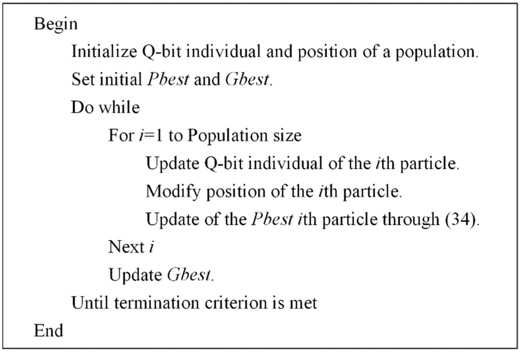
The procedure of the QB-PSO based solving method for the problem of communication structure optimization can be summarized as the following pseudo-code shown in Figure 3.

Figure 3.
Pseudo-code of the QB-PSO based solving method for the problem of communication structure optimization.
Further, the frequency regulation of the multi-area power system can be achieved based on the optimized communication structure. The working procedure of the approach for the frequency regulation of the multi-area power system is shown in Figure 4. Suppose that at time t the controller receives the area frequency deviation Δfi(t) because of the tripping of a generator or other sudden circumstances, and the control signal can be obtained. It should be noted that this paper focuses on the analysis of the influences of the communication structure on the frequency regulation, and how to obtain the signal is not discussed. This paper uses the traditional droop control to obtain the signal. Then, the whole power system would response to the frequency event according to Equation (15), which includes the behaviors of all areas of the power system. The frequency regulation would continue until the system dynamics achieve a new balance.
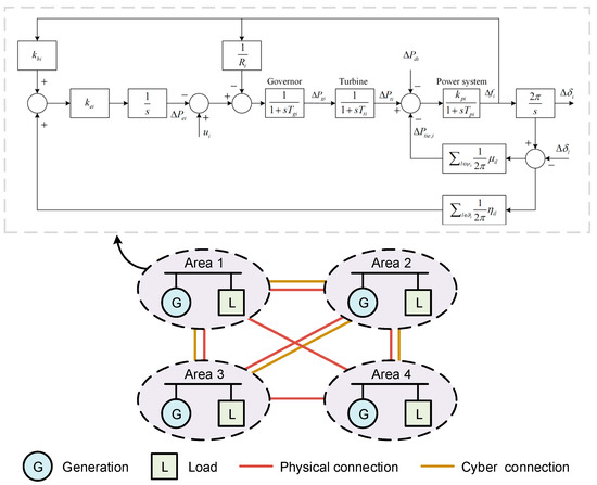
Figure 4.
Working procedure of the approach for the frequency regulation of the multi-area power system.
4. Case Study
4.1. Studied System and Communication Structure Optimization Result
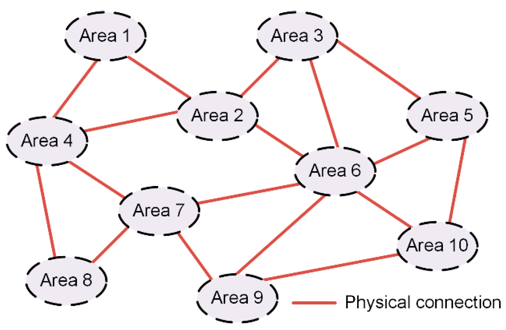
In this section, the simulation studies are carried out based on a ten-area interconnected power system, so as to investigate the performance of the proposed control method considering the communication structure optimization. The physical connection of the multi-area power system is shown in Figure 5, and the matrices of the parameters of Ai and Bi of the areas are listed in Equations (35)–(37). The parameters of Ci of the areas are not listed because they can be easily obtained using Ai and the physical connection.
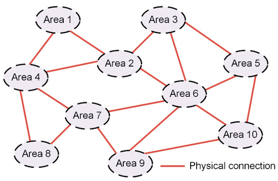
Figure 5.
Physical connection of the multi-area power system.
For area 1–3,
For area 4–6,
For area 7–10,
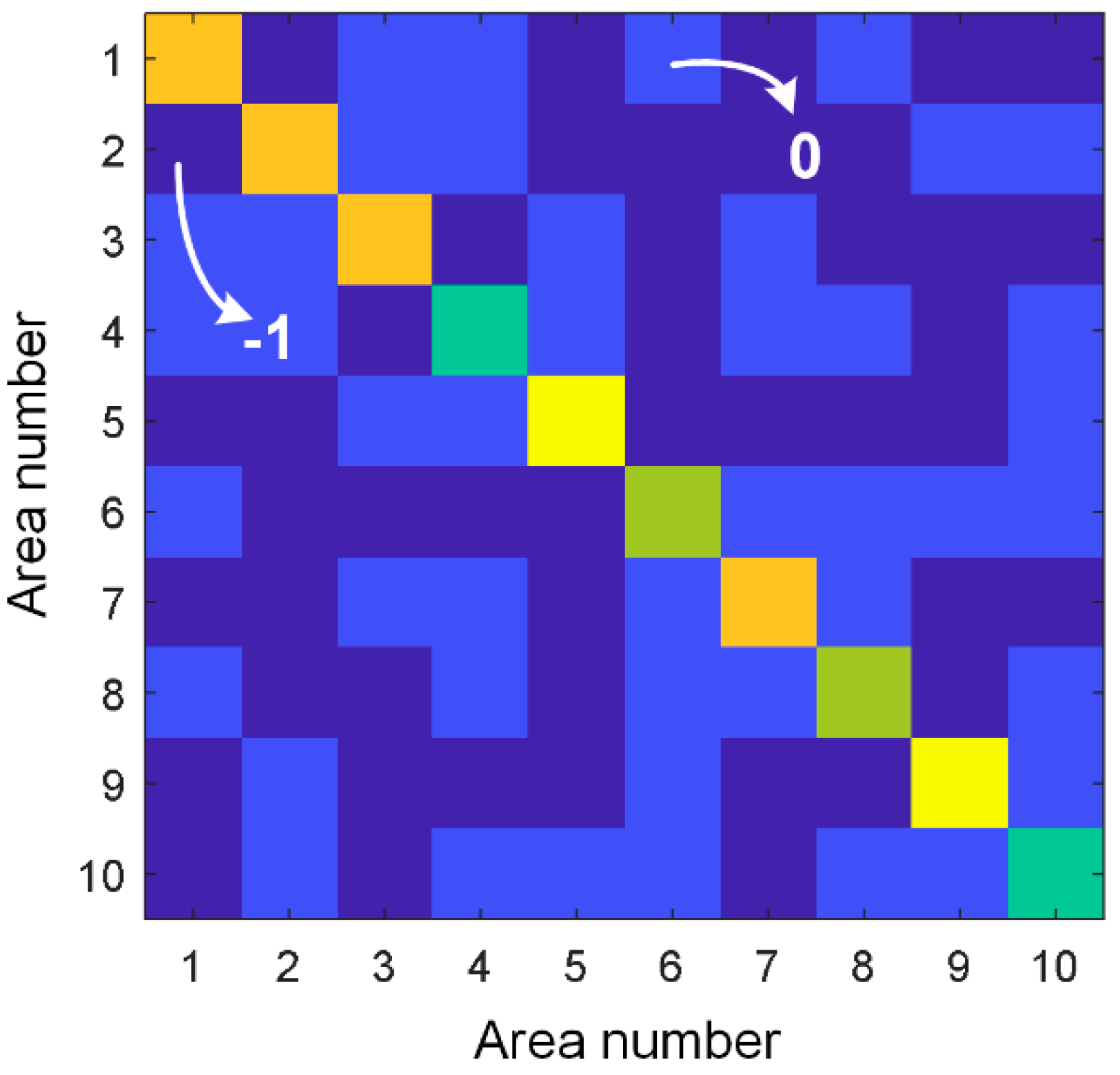
Based on the multi-area power system shown in Figure 5 and the parameters in Equations (35)–(37), the communication structure optimization can be carried out using QB-PSO. Set the maximum number of the communication links to be 25. The optimization results of Lc for the communication structure is shown in Figure 6.
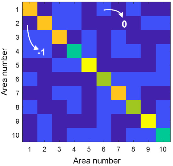
Figure 6.
Optimization results of Lc for the communication structure.
4.2. Advantage of Communication Structure Optimization for Frequency Regulation
In this section, we verify the advantage of communication structure optimization for frequency regulation under several different frequency events. We change the values of u in Equation (19) to imitate different frequency events, which are
Frequency event A: u = [5 0 0 0 0 0 0 0 0 0 0 0 0 0 0 0 0 0 0 0];
Frequency event B: u = [0 0 −4 0 0 0 0 0 0 0 0 0 0 0 0 0 0 0 0 0];
Frequency event C: u = [0 2 0 0 0 0 0 3.3 0 0 0 0 0 0 0 0 0 0 0 0];
Frequency event D: u = [0 3 0 0 0 0 0 0 0 0 0 0 0 0 0 0 3 0 0 0];
Frequency event E: u = [5 0 0 0 0 0 0 0 0 0 0 0 8 0 0 0 0 0 0 0].
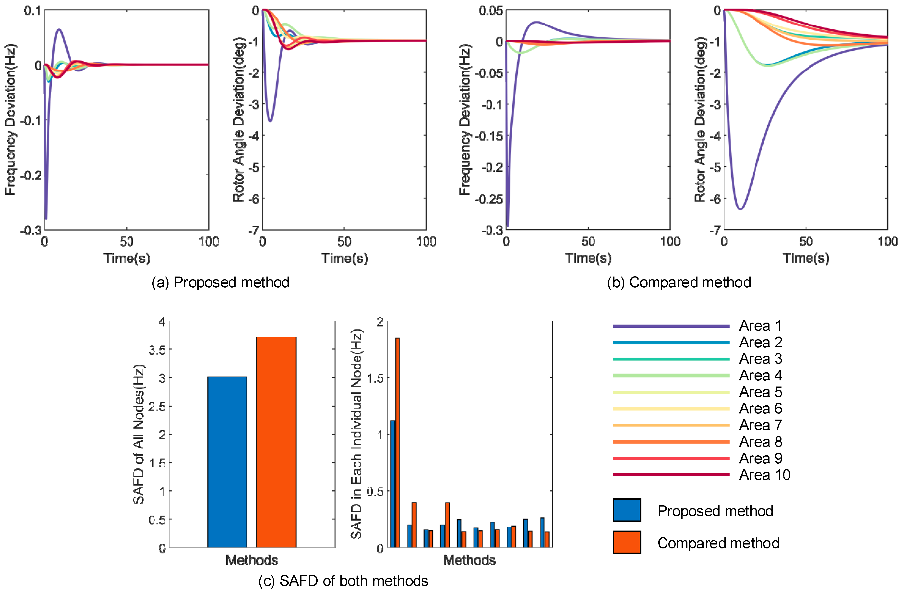
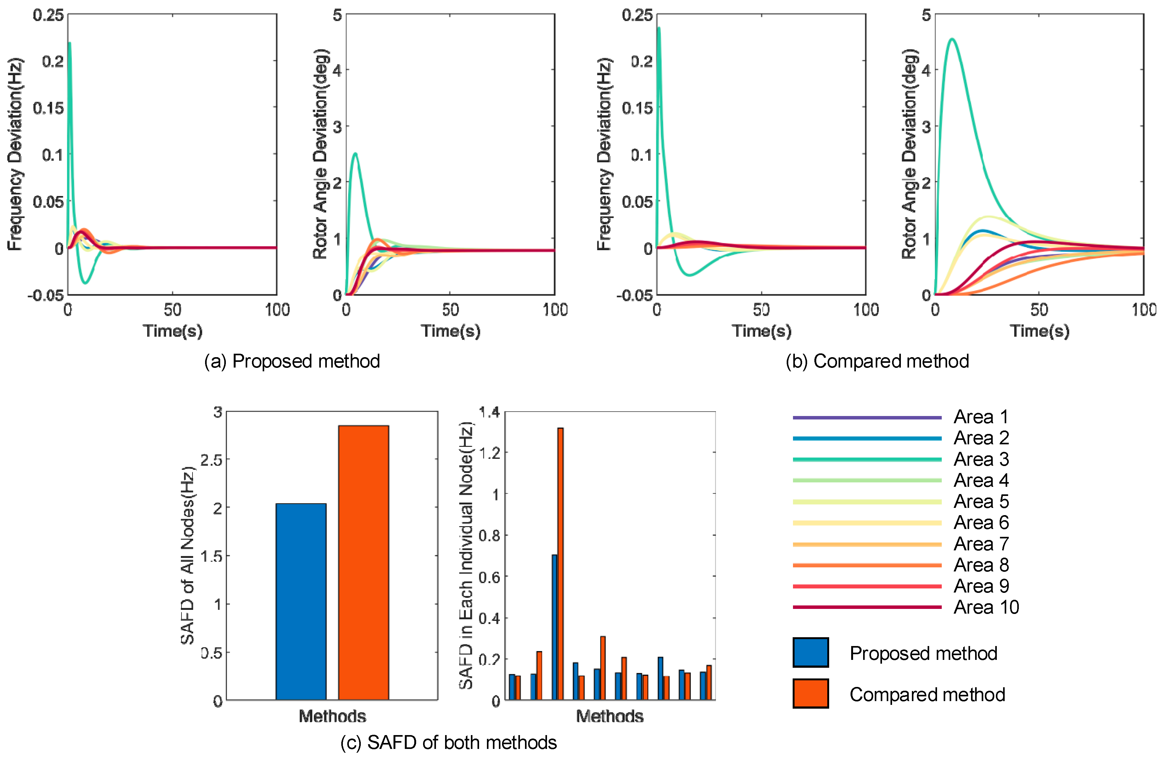
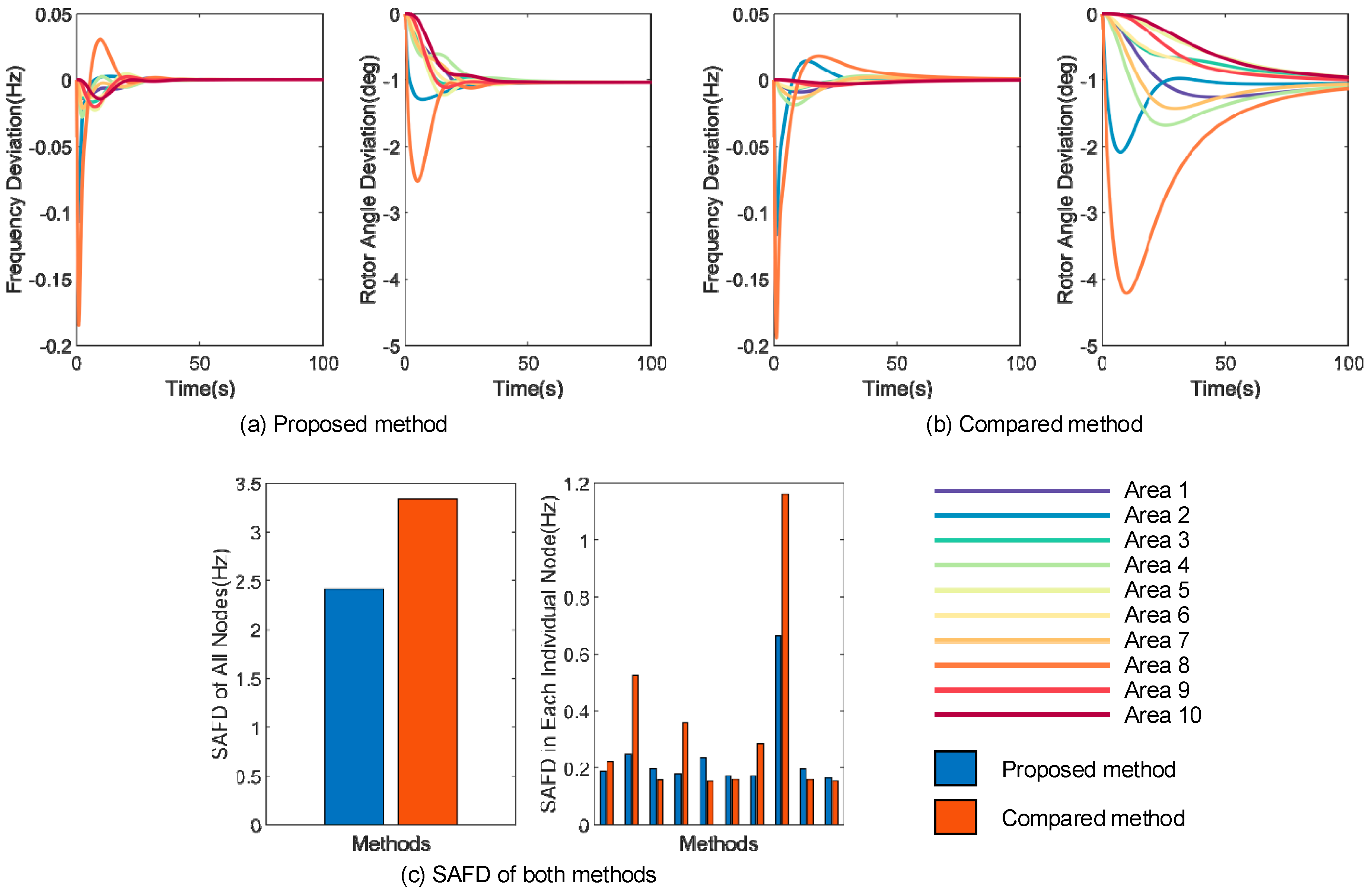
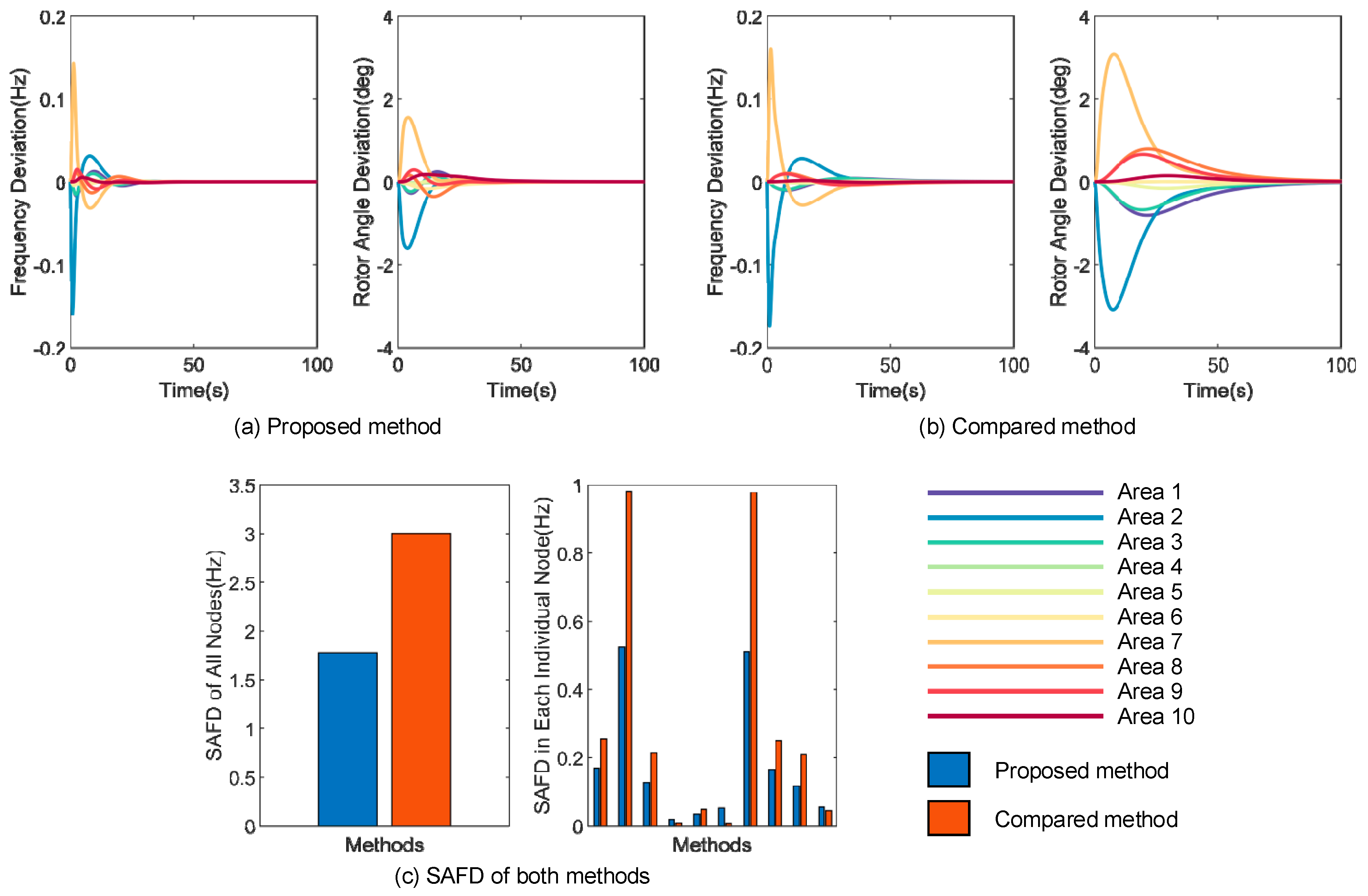
For comparison, we use the frequency regulation method in the case where the graph of physical connection of the power system and the graph of the communication network are totally the same. Based on these frequency events, the frequency regulation processes are simulated, and the frequency deviation and rotor angle deviation of both methods are shown in Figure 7, Figure 8, Figure 9, Figure 10 and Figure 11. Besides, the sum of absolute frequency deviation (SAFD) of all nodes and each individual node of both methods are also shown in Figure 7, Figure 8, Figure 9, Figure 10 and Figure 11.
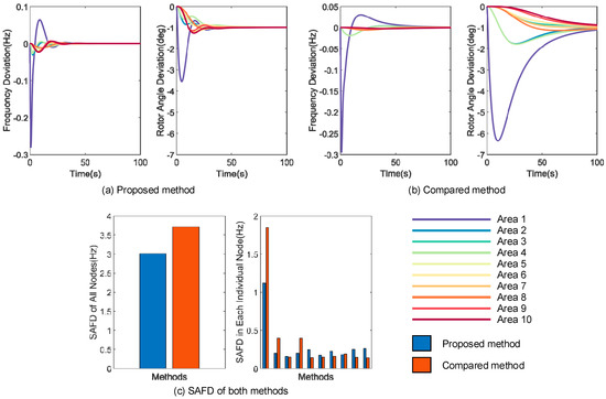
Figure 7.
Frequency deviation, rotor angle deviation and sum of absolute frequency deviation (SAFD) of both methods in the frequency event A.
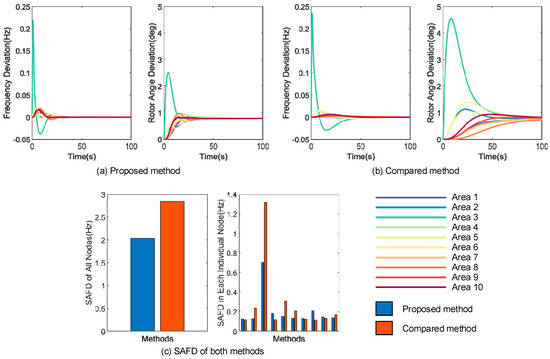
Figure 8.
Frequency deviation, rotor angle deviation and sum of absolute frequency deviation (SAFD) of both methods in the frequency event B.
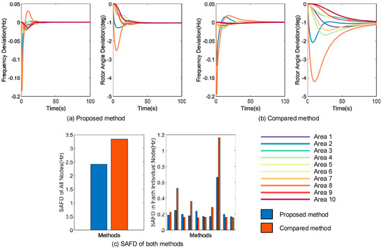
Figure 9.
Frequency deviation, rotor angle deviation and sum of absolute frequency deviation (SAFD) of both methods in the frequency event C.

Figure 10.
Frequency deviation, rotor angle deviation and sum of absolute frequency deviation (SAFD) of both methods in the frequency event D.
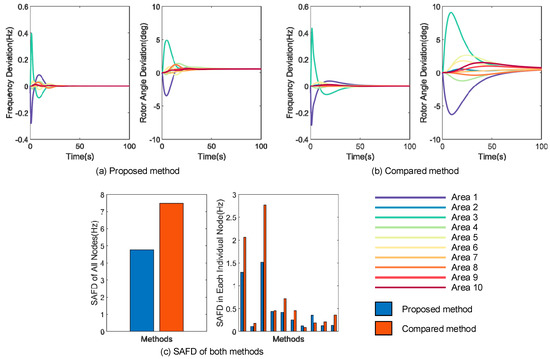
Figure 11.
Frequency deviation, rotor angle deviation and sum of absolute frequency deviation (SAFD) of both methods in the frequency event E.
Intuitively, as can be seen in Figure 7a,b, Figure 8a,b, Figure 9a,b, Figure 10a,b and Figure 11a,b, the frequency and the rotor angle go through short-time transition and achieve stable state with the proposed method, and the convergence speed of the proposed method is much faster in all five different frequency events. In contrast, for the compared method, the convergence processes are much slower. The reason is that the proposed method increases the value and decreases the value of the eigenvalue of the matrix A through QB-PSO based optimization. With the which reflects the algebraic connectivity of the communication network, a larger means that the network is better connected and the information can be faster shared across the network. For the eigenvalues of the matrix A, if the largest one is less than 0 and quite far from 0, the system would also acquire faster convergence speed. Thus, under the condition of larger and smaller eigenvalue of the matrix A after QB-PSO based optimization, the speed of convergence (or performance) of the control algorithm is much faster.
In addition, as can be seen in Figure 7c, Figure 8c, Figure 9c, Figure 10c and Figure 11c, the SAFDs of the proposed method are much smaller than in the compared method, in terms of all nodes and each individual node. This indicates that the proposed method goes through the transient process with less time. Although there are some oscillations during the frequency regulation for the proposed method, its amplitude of the oscillations is not larger than the compared method and the process of the oscillation is short-lived. Thus, the proposed control method can improve the frequency control performance by the optimization of the communication structure.
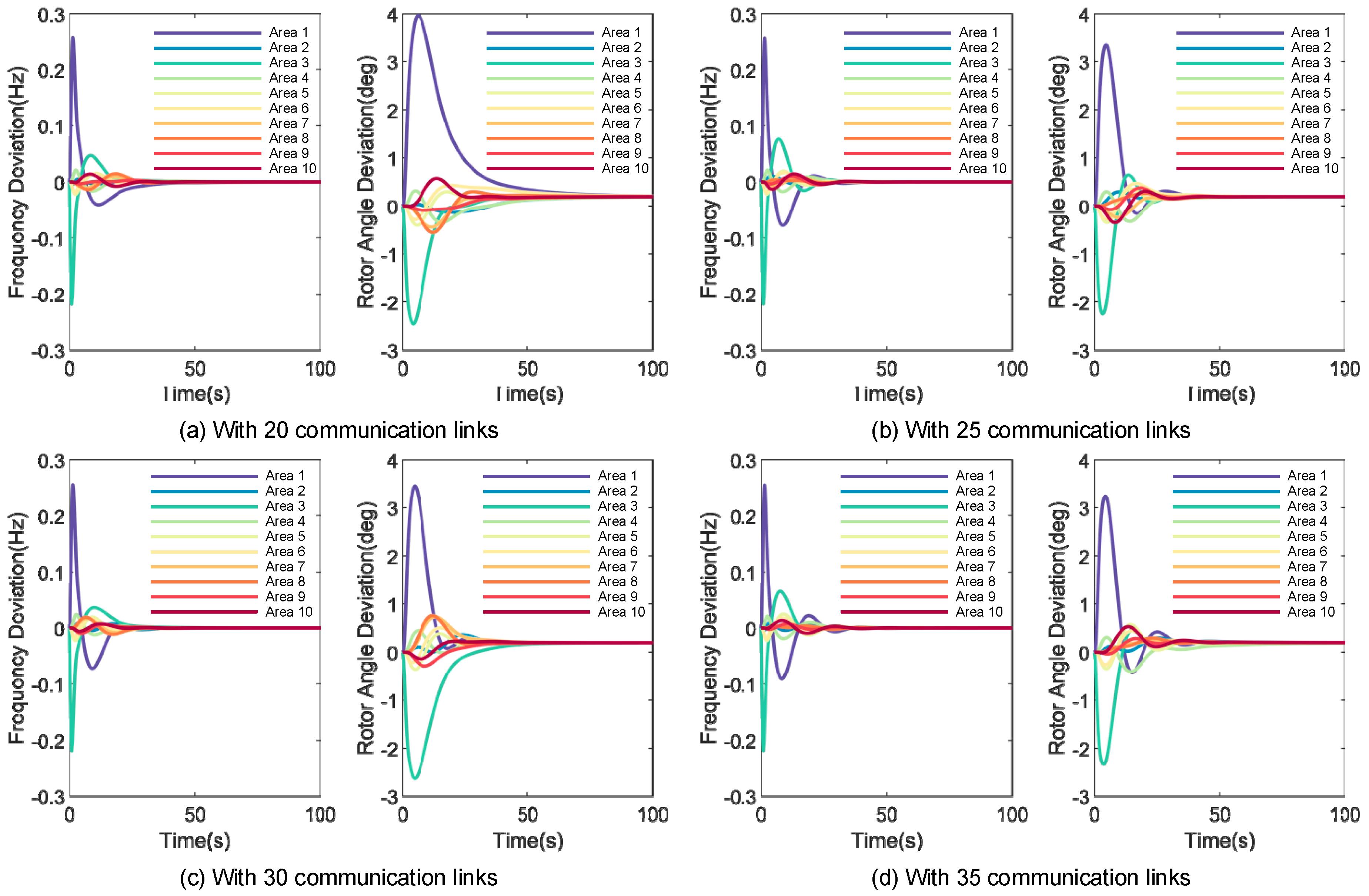
4.3. Frequency Regulation with Different Numbers of Communication Links
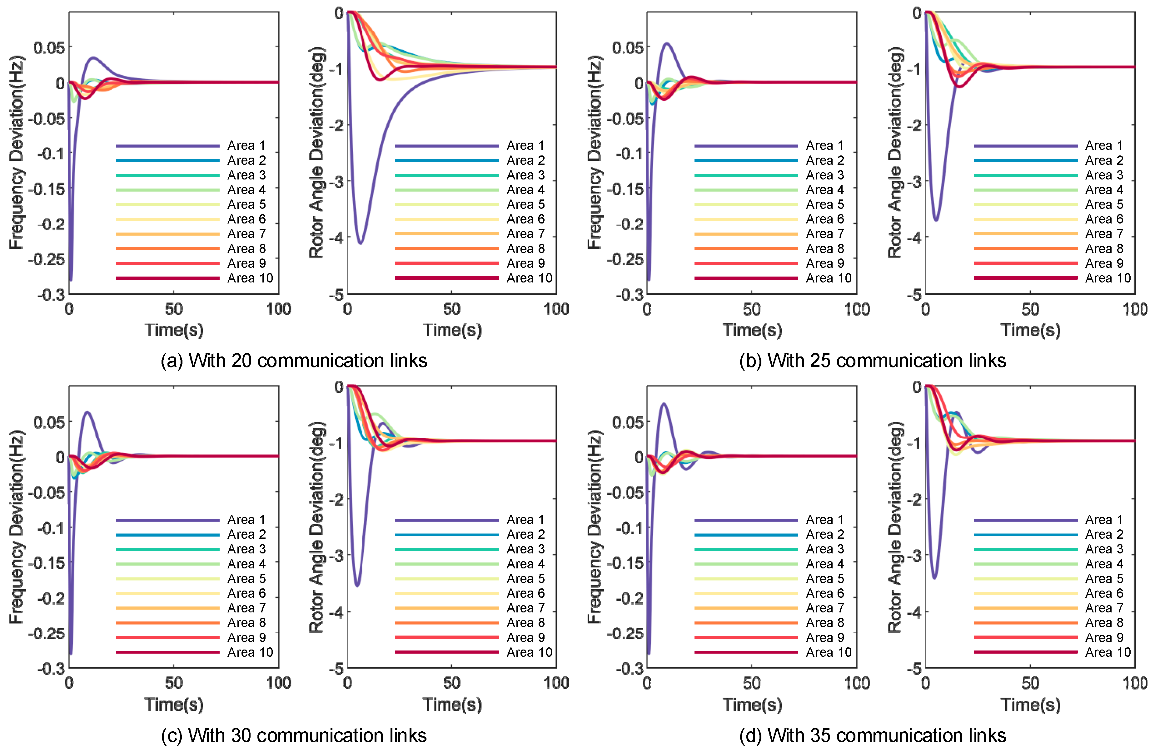
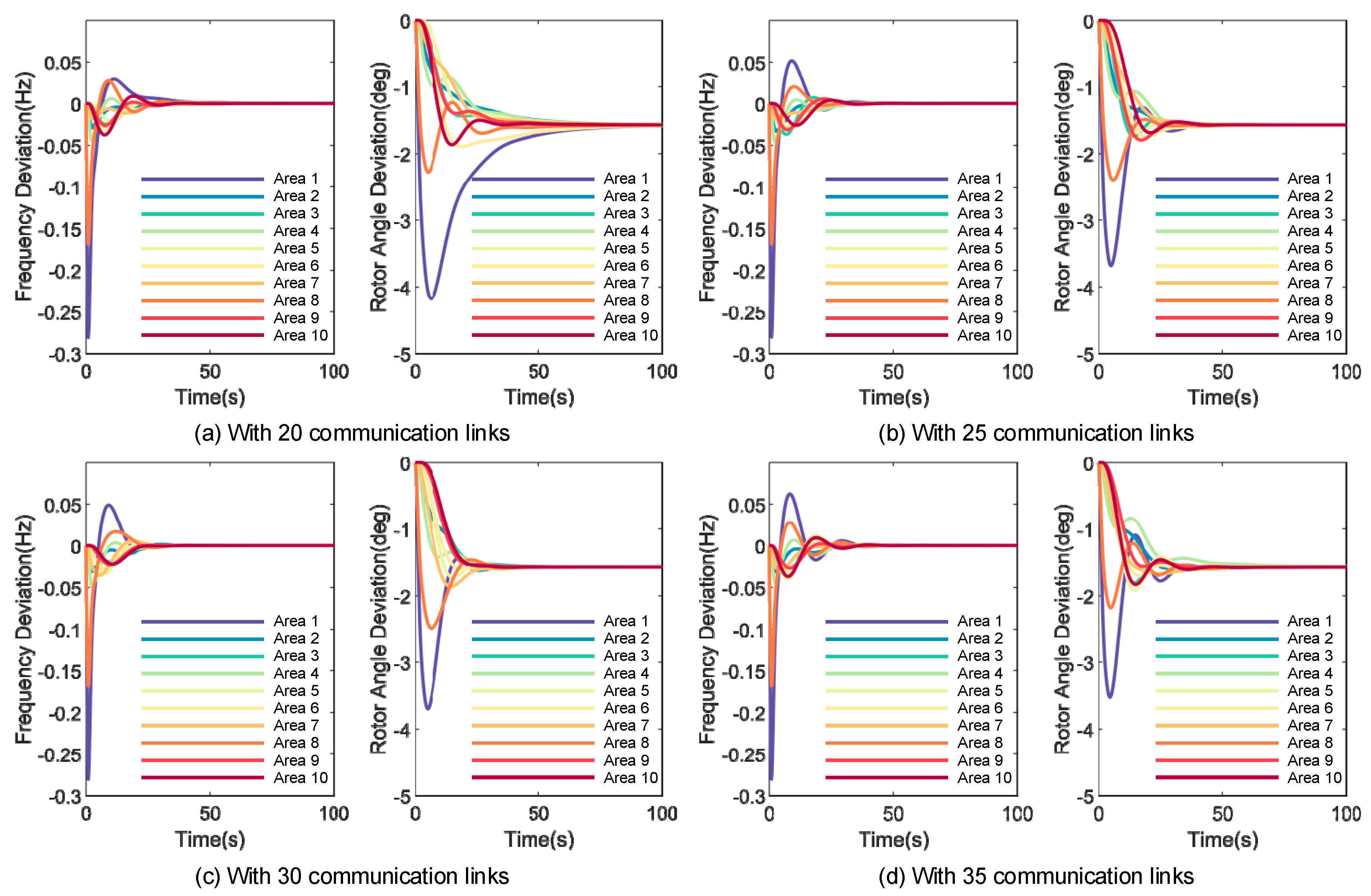
In this section, we test the performance of the frequency regulation with different numbers of communication links. With the proposed method which optimizes the structure of the communication network, there is an important pre-set parameter, i.e., the number of the communication links Numc. Generally speaking, a larger value of Numc means that the network tends to be fully connected. We pre-set the value of Numc to be 20, 25, 30 and 35, and use the following different frequency events in the test
Frequency event F: u = [5 0 0 0 0 0 0 0 0 0 0 0 0 0 0 0 0 0 0 0];
Frequency event G: u = [5 0 0 0 0 0 0 3 0 0 0 0 0 0 0 0 0 0 0 0];
Frequency event H: u = [0 0 4 0 0 0 0 0 0 0 5 0 0 0 0 0 0 0 0 0].
Table 1 shows the eigenvalue of the systems with 20, 25, 30 and 35 lines. Figure 12, Figure 13 and Figure 14 show the frequency deviation and rotor angle deviation of the proposed method and the compared method with different numbers of communication links in frequency event F–H. Figure 15 shows the SAFD of all nodes and each individual node of both methods with different numbers of communication links in frequency event F–H.

Table 1.
Eigenvalue of the systems with 20, 25, 30 and 35 lines.
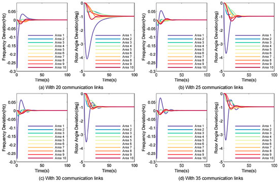
Figure 12.
Frequency deviation and rotor angle deviation of the proposed method and the compared method with different numbers of communication links in frequency event F.
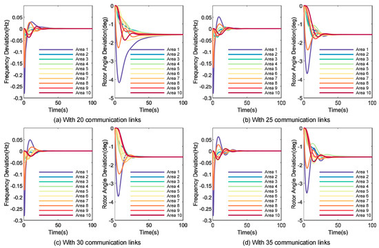
Figure 13.
Frequency deviation and rotor angle deviation of the proposed method and the compared method with different numbers of communication links in frequency event G.
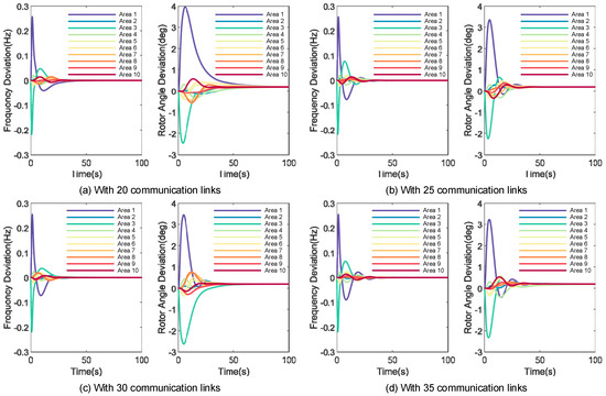
Figure 14.
Frequency deviation and rotor angle deviation of the proposed method and the compared method with different numbers of communication links in frequency event H.
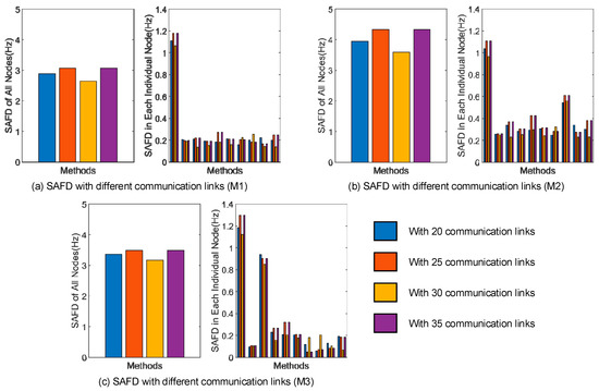
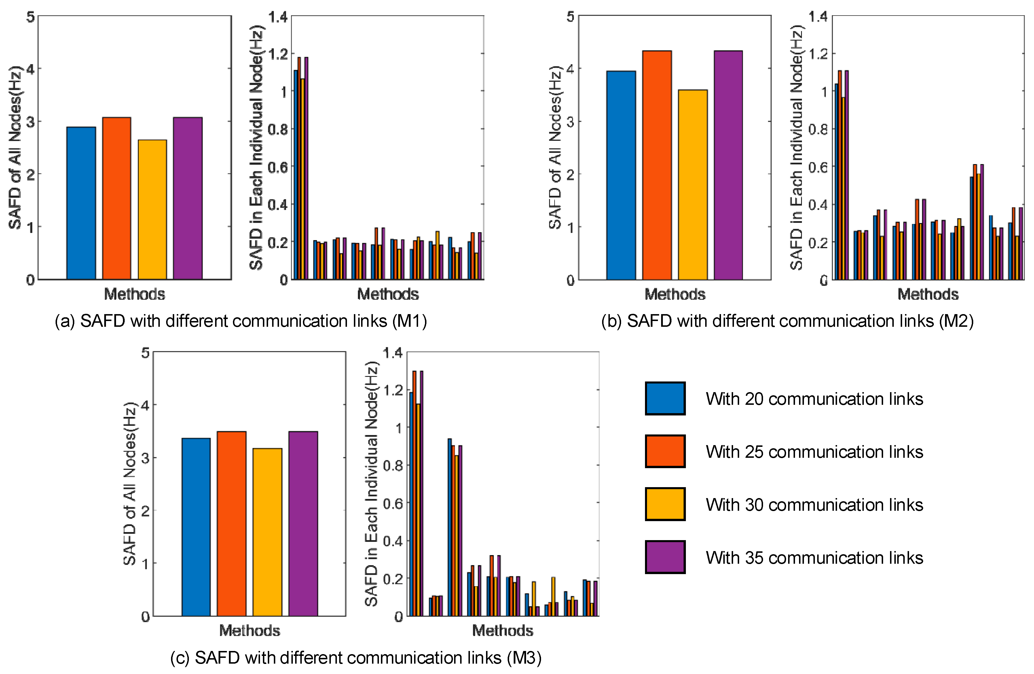
Figure 15.
SAFD of all nodes and each individual node of the proposed method and the compared method with different numbers of communication links in frequency events F–H.
Intuitively, as can be seen in Figure 12, Figure 13 and Figure 14, the frequency regulation performances are better in some circumstances of numbers of communication links. However, the performances seem not to get better and better with the value of Numc increasing. From Figure 15 we can see that the SAFDs are the smallest with the value of Numc = 25 in frequency event F–H, illustrating that the control goes through the most short-lived transient process with Numc = 25 in frequency event F–H. The reason can be summarized as follows: Although a larger value of Numc means better connectivity of the communication network, this does not indicate that larger Numc is beneficial for the convergence of the control. With larger Numc, the information shared among all nodes increases significantly, and each node may get the information of more nodes. The ample information may not be helpful to the convergence of the control. Thus, it is suggested to try more values of Numc to find a better frequency regulation performance. In the tested system, through a series of experiments, we suggest Numc = 25 to acquire the possibly most satisfactory frequency regulation performance.
5. Conclusions
This paper presents a decentralized frequency regulation method for a multi-area power system considering optimization of communication structure, and it studies the influence of the communication structure on the frequency regulation performance. The model of the communication network and of the multi-area power system is described firstly. Then, the frequency regulation method considering optimization of communication structure is presented. Main conclusions are listed as follows: First of all, under the condition of larger algebraic connectivity and smaller eigenvalue of the matrix A after QB-PSO based optimization, the speed of convergence (or performance) of the frequency control algorithm is much faster. Moreover, we discovered that the number of the communication links has a great influence on the control convergence speed. However, more communication links may not be beneficial for the convergence speed of frequency. It is suggested to try more values of communication links to find a better frequency regulation performance, and this is also our future work.
Author Contributions
Y.W. put forward the research direction, completed the principal analysis and the method design, performed the simulation, and drafted the article. J.H. organized the research activities, provided theory guidance, and completed the revision of the article. All eight were involved in revising the paper. All authors have read and agreed to the published version of the manuscript.
Funding
This research was funded by the State Grid Hubei Electric Power Company Science and Technology Project (No. 521538220007).
Institutional Review Board Statement
Not applicable.
Informed Consent Statement
Not applicable.
Data Availability Statement
Not applicable.
Conflicts of Interest
The authors declare no conflict of interest.
References
- Parmar, K.S.; Majhi, S.; Kothari, D. Load frequency control of a realistic power system with multi-source power generation. Int. J. Electr. Power Energy Syst. 2012, 42, 426–433. [Google Scholar] [CrossRef]
- Pandey, S.K.; Mohanty, S.R.; Kishor, N. A literature survey on load-frequency control for conventional and distribution generation power systems. Renew. Sustain. Energy Rev. 2013, 25, 318–334. [Google Scholar] [CrossRef]
- Saxena, S.; Hote, Y.V. Load frequency control in power systems via internal model control scheme and model-order reduction. IEEE Trans. Power Syst. 2013, 28, 2749–2757. [Google Scholar] [CrossRef]
- Sarasúa, J.I.; Martínez-Lucas, G.; Platero, C.A.; Sánchez-Fernández, J.Á. Dual Frequency Regulation in Pumping Mode in a Wind–Hydro Isolated System. Energies 2018, 11, 2865. [Google Scholar] [CrossRef]
- Martínez-Lucas, G.; Sarasúa, J.I.; Sánchez-Fernández, J.Á. Frequency Regulation of a Hybrid Wind–Hydro Power Plant in an Isolated Power System. Energies 2018, 11, 239. [Google Scholar] [CrossRef]
- Muñoz-Benavente, I.; Hansen, A.D.; Gómez-Lázaro, E.; García-Sánchez, T.; Fernández-Guillamón, A.; Molina-García, Á. Impact of Combined Demand-Response and Wind Power Plant Participation in Frequency Control for Multi-Area Power Systems. Energies 2019, 12, 1687. [Google Scholar] [CrossRef]
- Vlahakis, E.; Dritsas, L.; Halikias, G. Distributed LQR Design for a Class of Large-Scale Multi-Area Power Systems. Energies 2019, 12, 2664. [Google Scholar] [CrossRef]
- Gulzar, M.M.; Iqbal, M.; Shahzad, S.; Muqeet, H.A.; Shahzad, M.; Hussain, M.M. Load Frequency Control (LFC) Strategies in Renewable Energy-Based Hybrid Power Systems: A Review. Energies 2022, 15, 3488. [Google Scholar] [CrossRef]
- Yousef, H.; Al-Kharusi, K.; Albadi, M.H.; Hosseinzadeh, N. Load frequency control of a multi-area power system: An adaptive fuzzy logic approach. IEEE Trans. Power Syst. 2014, 29, 1822–1830. [Google Scholar] [CrossRef]
- Khodabakhshian, A.; Edrisi, M. A new robust PID load frequency controller. Control Eng. Pract. 2008, 16, 1069–1080. [Google Scholar] [CrossRef]
- Vachirasricirikul, S.; Ngamroo, I. Robust LFC in a smart grid with wind power penetration by coordinated V2G control and frequency controller. IEEE Trans. Smart Grid 2014, 5, 371–380. [Google Scholar] [CrossRef]
- Chuang, N. Robust H load-frequency control in interconnected power systems. IET Control Theory Appl. 2016, 10, 67–75. [Google Scholar] [CrossRef]
- Sahu, R.K.; Panda, S.; Pradhan, P.C. Design and analysis of hybrid firefly algorithm-pattern search based fuzzy PID controller for LFC of multi area power systems. Int. J. Electr. Power 2015, 69, 200–212. [Google Scholar] [CrossRef]
- Mohseni, N.A.; Bayati, N. Robust Multi-Objective H2/H∞ Load Frequency Control of Multi-Area Interconnected Power Systems Using TS Fuzzy Modeling by Considering Delay and Uncertainty. Energies 2022, 15, 5525. [Google Scholar] [CrossRef]
- Mu, C.; Tang, Y.; He, H. Improved sliding mode design for load frequency control of power system integrated an adaptive learning strategy. IEEE Trans. Ind. Electron. 2017, 64, 6742–6751. [Google Scholar] [CrossRef]
- Liao, K.; Xu, Y. A robust load frequency control scheme for power systems based on second-order sliding mode and extended disturbance observer. IEEE Trans. Ind. Inform. 2018, 14, 3076–3086. [Google Scholar] [CrossRef]
- Liu, F.; Li, Y.; Cao, Y.; She, J.; Wu, M. A two-layer active disturbance rejection controller design for load frequency control of interconnected power system. IEEE Trans. Power Syst. 2016, 31, 3320–3321. [Google Scholar] [CrossRef]
- Ersdal, A.M.; Imsland, L.; Uhlen, K. Model predictive load-frequency control. IEEE Trans. Power Syst. 2016, 31, 777–785. [Google Scholar] [CrossRef]
- Yan, Z.; Xu, Y. A multi-agent deep reinforcement learning method for cooperative load frequency control of a multi-area power system. IEEE Trans. Power Syst. 2020, 35, 4599–4608. [Google Scholar] [CrossRef]
- Gupta, D.K.; Jha, A.V.; Appasani, B.; Srinivasulu, A.; Bizon, N.; Thounthong, P. Load Frequency Control Using Hybrid Intelligent Optimization Technique for Multi-Source Power Systems. Energies 2021, 14, 1581. [Google Scholar] [CrossRef]
- Mi, Y.; Fu, Y.; Wang, C.; Wang, P. Decentralized sliding mode load frequency control for multi-area power systems. IEEE Trans. Power Syst. 2013, 28, 4301–4309. [Google Scholar] [CrossRef]
- Hai, T.P.; Cho, H.; Chung, I.-Y.; Kang, H.-K.; Cho, J.; Kim, J. A Novel Voltage Control Scheme for Low-Voltage DC Distribution Systems Using Multi-Agent Systems. Energies 2017, 10, 41. [Google Scholar] [CrossRef]
- Alrifai, M.; Hassan, F.; Zribi, M. Decentralized load frequency controller for a multi-area interconnected power system. Int. J. Electr. Power Energy Syst. 2011, 33, 198–209. [Google Scholar] [CrossRef]
- Delavari, A.; Kamwa, I. Improved optimal decentralized load modulation for power system primary frequency regulation. IEEE Trans. Power Syst. 2017, 33, 1013–1025. [Google Scholar] [CrossRef]
- Yang, Y.; Yang, P.; Lin, W.; Li, Z.; Lu, G. A decentralized control for Non-error frequency regulation in an islanded microgrid containing multiple VSGs. Int. J. Electr. Power Energy Syst. 2021, 133, 107337. [Google Scholar] [CrossRef]
- Olfati-Saber, R. Ultrafast Consensus in Small-World Networks. In Proceedings of the 2005 American Control Conference, Portland, OR, USA, 8–10 June 2005. [Google Scholar]
- Jin, Z.; Murray, R.M. Random consensus protocol in large-scale networks. In Proceedings of the IEEE Conference on Decision & Control IEEE, New Orleans, LA, USA, 12–14 December 2007. [Google Scholar]


Publisher’s Note: MDPI stays neutral with regard to jurisdictional claims in published maps and institutional affiliations. |
© 2022 by the authors. Licensee MDPI, Basel, Switzerland. This article is an open access article distributed under the terms and conditions of the Creative Commons Attribution (CC BY) license (https://creativecommons.org/licenses/by/4.0/).