Article

Techno-Economic Comparison of Utility-Scale Compressed Air and Electro-Chemical Storage Systems

by
Coriolano Salvini
* and
Ambra Giovannelli
Department of Industrial, Electronic and Mechanical Engineering, University of Roma TRE, 00154 Roma, Italy
*
Author to whom correspondence should be addressed.
Energies 2022, 15(18), 6644; https://doi.org/10.3390/en15186644
Submission received: 20 July 2022 / Revised: 26 August 2022 / Accepted: 7 September 2022 / Published: 11 September 2022
(This article belongs to the Special Issue Developing the World in 2021 with Clean and Safe Energy)

Abstract

:
The paper deals with a techno-economic comparison between utility-scale diabatic compressed air energy storage (D-CAES) systems equipped with artificial storage and Battery Energy Storage (BES) systems based on consolidated technologies, such as Sodium-Sulfur (Na-S) and Lithium-ion (Li-Ion). The comparison is carried out on the basis of the levelized cost of storage (LCOS). Analyses have been performed by varying key inputs, such as the rated power, the storage capacity, the price of electricity absorbed from the grid during the charging phase, and the cost of fuel fed to D-CAES during the discharge phase. Na-S technology-based systems always show better techno-economic performance in respect to Li-Ion based ones. The economic performance of both D-CAES and BES improves by increasing the storage capacity. The D-CAES performance improvement rate, however, is higher than that estimated for BES based systems. Moreover, the economic performance of D-CAES systems is less sensitive to the price of electricity in respect of BES based storage facilities. As a result, D-CAES based solutions can reach a LCOS lower than that of Na-S batteries if the size of the system and the price of electricity are large enough.

1. Introduction

In the last decade, the use of non-programmable renewable energy sources (RES) for electricity production has significantly increased worldwide. Such a growth has led to a relevant reduction of CO2 emissions and to a remarkable improvement of the sustainability of the overall energy system. Conversely, the intrinsic intermittency of non-programmable RES (mainly wind and sun) and the unpredictability in estimating their availability along the time pose serious problems in terms of safe, reliable and cost-effective operation of electric networks. Electric energy storage (EES) can play an important role in mitigating the above issues, thus further promoting the use of RES for electricity production.
The present paper focuses on typical EES applications suitable for RES promotion and integration, such as energy management and transmission upgrade deferral [1,2].
Such applications call for utility-scale EES facilities sized for a rated power ranging from one megawatt to one hundred megawatts and for charging/discharging periods in the order of hours or days [3]. Suitable technologies for the fulfillment of the above requirements are pumped hydro storage (PHS), battery energy storage (BES), and compressed air energy storage (CAES).
A crucial point addressed in the present paper concerns to the actual feasibility of EES under consideration. Therefore, only well-established technologies suitable to arrange utility-scale EES systems will be taken into consideration.
PHS is presently the most consolidate and cost-effective technology for large capacity energy storage systems. PHS systems are characterized by a really long operating lifetime (up to 100 years [4]), adequate roundtrip efficiency (typically in the range of 70–80%), and charging/discharging period durations in the order of few hours to few days. As reported in [5], PHS accounts for about 96% of the global storage power capacity. Despite this, it should be stressed that the construction of new plants—especially in developed countries- is hindered by the shortage of new suitable sites and by the impact on the environment of the artificial water reservoir.
BES based systems are extensively used for small scale applications. Since in the present work the actual feasibility of storage systems is regarded as a major issue, only consolidated commercially available BES technologies are taken into consideration: Lead-Acid (Pb-Acid) batteries, Sodium-Sulfur (Na-S) batteries, Lithium-ion (Li-ion) batteries, and redox flow batteries (RFB).
In [1], Xing et al. report and discuss grid-scale applications based on the abovementioned technologies:
  • Pb-Acid based installations ranging from 1 MW–1.4 MWh to 36 MW–24 MWh;
  • Na-S facilities, from 1 MW–7 MWh to 34 MW–245 MWh;
  • Li-ion based storage systems, from 6 MW–10 MWh to 32 MW–8 MWh;
  • RFB based systems, from 0.2 MW–0.8 MWh to 2 MW–12 MWh.
Pb-Acid batteries have been employed for grid-scale electricity storage for several years. More recently, a system with 1 MW peak output and a storage capacity of 3 MWh has been installed at Lerwick (Shetland Isles, Scotland) in 2013. The system has been successfully operated to reduce peak demand for diesel generation and increase the proportion of usable wind power [2]. A large hybrid Pb-Acid battery/supercapacitor was installed in 2012 in Pennsylvania (USA) for frequency regulation. The system, consisting of four batteries each connected to a 900 kW inverter, can exchange with the electric grid a power of 3 MW [2]. Finally, a 3 MW system was installed on King Island (Tasmania) to complement the generating units of the local electric grid. The storage system, fed by surplus electricity generated from RES (wind and sun), has led to a significant reduction of the amount of fossil fuel required to meet the electricity demand [2].
Three storage facilities based on Na-S batteries were commissioned in 2016 by the Italian Transmission System Operator (TERNA) to reduce wind energy curtailments. The total installed power amounts to 35 MW, with an overall storage capacity of 350 MWh [6]. Another noticeable application of Na-S batteries is the 34 MW–204 MWh plant installed at Rokkasho (in northern Japan) to reduce RES curtailment and provide ancillary services. The system is connected to a 50 MW wind farm: the electricity produced in excess is stored and sold to the grid during peak hours. In addition, the storage system provides frequency regulation and minute reserve [7].
The US company San Diego Gas & Electric commissioned in 2017 a 30 MW–120 MWh storage facility based on Li-ion batteries (manufactured by Samsung SDI) to absorb excess of RES production and to enhance the regional grid reliability [8]. A 100 MW–139 MWh Li-Ion storage system (based on Tesla batteries) was put into operation in Australia in December 2017 to provide quick reserve and ancillary services to the South-Australian grid [9]. An additional expansion of 50 MW/64.5 MWh is foreseen, as reported in [10]. Other relevant Australian utility-scale projects based on Li-Ion technology for a total of about 110 MW and 140 MWh are listed in [10]. According to Zakery and Syri [11], the future perspective of Li-ion technology for grid-scale applications seems to be really promising due to the expected cost and performance improvements. Such improvements are related to the intense R&D ongoing activities aimed at enhancing both electrochemical performance and manufacturing process, as reported, for example, in [12,13].
The main advantage of RFB in respect to other BES technologies is that power and energy ratings can be set independently. Therefore, RFB based storage systems can be optimized according to the particular application under consideration [14]. Relevant drawbacks are the relatively low power and energy density in comparison to other BES technologies [15] and the high capital costs [11]. Prevailing VRF technologies are Vanadium redox battery (VRB) and Zinc-Bromine (Zn-BR). The largest VRF based storage system (100 MW–400 MWh) has been commissioned in May 2022 in Dalian, PRC [16]. The system has been conceived to lower peak loads, to improve the power supply and to promote the use of renewables. Previously, the biggest VRF based facility was a 15 MW–60 MWh system deployed in 2015 in northern Japan by Sumitomo Electric. A noticeable 25 MW–100 MWh system based on Zn-Br technology has been installed in Kazakhstan for energy time-shift, as reported in [17].
On the basis of data gathered by IRENA regarding utility-scale applications, Li-ion batteries constitute the majority of newly installed capacity in the period 2011–2016. Conversely, Pb-Acid technology appears to be declining, while Na-S and RFB maintain an average share of about 10% and less than 3%, respectively [7].
The levelized cost of storage (LCOS), discussed in detail in Section 3, is an index commonly used to assess the techno-economic performance of EES systems. Based of recently published studies [7,18,19], VRB and Pb-Acid based systems batteries show higher LCOS in respect to Li-ion and Na-S ones. As an example, for a storage system size comparable to those considered in the present work (case S2 discussed in [19]), Na-S and Li-ion based systems show a similar LCOS of about 300 USD/kWh, while Pb-Acid and VRB have considerable higher values of 475 and 425 USD/kWh, respectively.
As a consequence, taking the current trend and recent studies into account [7,11], and looking also at the rated power and storage capacity of the recently commissioned plants, in the present paper, only Li-Ion and Na-S technologies will be considered.
Compressed air energy storage (CAES) represents an attractive option for massive energy storage applications. In CAES plants, surplus electricity available on the grid is absorbed to drive an air compressor. The compressed air can be stored in a natural or artificial reservoir and subsequently used to produce electricity during peak periods. Starting from this basic principle, three main CAES concepts have been proposed: diabatic CAES (D-CAES), adiabatic CAES (A-CAES), and isothermal CAES (I-CAES). Presently, only D-CAES can be considered a mature and consolidated technology [20,21] and, therefore, according to what previously stated about feasibility requirements, the only technology here considered.
In a D-CAES (Figure 1a), to improve both output power and efficiency, an external energy source, typically a fossil fuel, is employed to heat the compressed air before expansion. However, different heat sources, such as industrial waste heat, heat engine exhaust, or solar heat, were proposed and investigated, as reported by Chen et al. [22], Li et al. [23], and Salvini [24,25].
Commercial D-CAES existing plants (Huntorf and McIntosh plants) have large capacities (320 and 110 MW respectively) and underground air storage, typically salt caverns. The Huntorf plant (in operation from 1978) was originally conceived to allow baseload operation to a nuclear plant and for providing emergency electric power in the case of a network breakdown. It was later used to deliver minute reserve (i.e., reserve power available within a few minutes) and for peak shaving. A more recent application is related to the noteworthy growth of wind farms in North Germany: the storage plant is used to compensate the loss of generation due to unexpected shortage of wind energy or to absorb the excess of electricity produced in time periods of large wind availability [26]. The McIntosh plant (commissioned in 1991) is characterized by a higher efficiency in respect to the Huntorf plant (54% vs. 42%, as reported in [21]). This is mainly due to the preheating of the combustion air carried out by recovering thermal energy from the high temperature gas discharged by the expander [27].
Following these successful applications, several well-planned commercial projects, mostly based on the well proven diabatic CAES concept, have been stalled and, in the end, abandoned. The reasons for such failures are analyzed and discussed by Budt et al. [21]. Most of these reasons are common to all the electric storage systems competitive with CAES, such as PHS and BES: the narrowing of the gap between peak/off-peak price of electricity and the increased operational flexibility of both electric grids and generation plants. Peculiar drawbacks of D-CAES are, instead, the lower roundtrip efficiency in comparison to PHS and BES, the need to use an a heat external source, and the location constraints related to the availability of suitable natural reservoirs.
Anyway, in agreement with Budt et al. [21], the authors believe that decentralized small/medium size CAES systems could be effectively used for off-grid and self-consumption applications as well as for the supply of ancillary services, e.g., secondary and tertiary reserve.
Such applications, together with those previously mentioned to further promote the use of RES for electric generation (i.e., energy management and transmission upgrade postponement), call for utility-scale storage facilities conveniently located on the electric grid. Therefore, to avoid constraints arising from plant siting, only the BES based technologies already selected (Na-S and Li-ion) and D-CAES plants equipped with artificial reservoir will be considered.
The present paper is an extension of a study [28] presented at the International Conference on Energy and Environment Research (ICEER 2021). In order to achieve more general conclusions, the techno-economic performance of storage technologies under consideration is assessed in a suitable range of design rated power and storage capacity. The influence of other crucial quantities, such as the price of electricity absorbed during the charging phase and the cost of fuel fed to D-CAES during the discharge phase, is also investigated.

2. Storage Systems Description and Modelling

In this section, the storage systems under comparison and the adopted modelling approaches are described. BES based facilities, unlike CAES plants, due to their modular design can be scaled-up to fulfil any required storage capacity by arranging in parallel an appropriate number of elementary units. Consequently, a simple approach based on a few global design quantities and performance indexes can be applied effectively to model BES systems under consideration. Conversely D-CAES systems with an artificial reservoir, especially regarding machinery and heat transfer devices, benefit from the scale effect, such that the larger the size of the system, the lower the cost per unit of installed power. Moreover, D-CAES techno-economic performance depends on a set of design parameters defining the thermo-dynamic processes occurring in the plant, such as the storage pressure, the temperature at the expander inlet, and so on. As a consequence, a more complex modelling approach is required.

2.1. D-CAES Plant Description and Modelling

The D-CAES layout here considered is depicted in in Figure 1a. It consists of a four-stage, intercooled, and after-cooled compressor train (CT), an artificial air storage tank (AST), a combustion chamber (CC), a gas expander (GE), and an air pre-heater (APH).
Figure 1b gives a representation of the T–s (temperature-entropy) diagram of thermodynamic processes occurring in plant components. For ease of representation, the actual intercooled/after-cooled compression is replaced by an isothermal process. As a consequence, the complete charge of the storage tank from pressure pIN to pressure pST is represented by a straight line connecting point A to point B.
The GE is assumed to operate in a constant pressure mode. The GE inlet pressure pGE,IN is kept constant during the discharge phase by the control valve CV, represented in Figure 1b. This control mode entails throttling losses, but, on the other hand, it facilitates plant operations. This is because, in both D-CAES existing plants, Huntorf and McIntosh, such a control mode has been preferred [21,26]. During discharge, the pressure inside the reservoir p(t) -point C on the diagram- decreases from pST to pIN. According to the adopted control mode, the air drawn from the reservoir is throttled in order to achieve the desired pressure set point pGE,IN at the GE inlet (line CD). The air is then preheated up the temperature TAPH in the APH (line DE) and, subsequently, fed to the CC where its temperature is raised up to the value TGE,IN (line EF). The combustion gas is then expanded in the GE (line FG), cooled in the APH (line GH) and, lastly, discharged into the atmosphere.
The D-CAES thermodynamic performance is assessed by using the computational model developed by the Authors [29] briefly described in Appendix A. Model output quantities (mass flows, pressures, temperatures, powers, etc.) constitute the input to size main plant components. Outcomes of sizing calculation (i.e., lengths, areas, volumes, weights etc.) are, in turn, input quantities for investment and operational cost estimations. The plant investment cost is evaluated by adopting an individual cost factor approach, in compliance with [30].
According to [31,32], an air storage system constituted by sections of large outer diameter (OD) steel pipe welded together and connected by manifolds has been adopted. Such a solution represents the most cost effective one for storage pressure up to 150 bar, according to [33]. The overall design philosophy is based on the well-established natural gas pipeline technology, as discussed in [32]. The volume V required to store the mass of air mCH to be introduced into the reservoir to accomplish a complete charge from the initial pressure pIN to the final pressure pST is given by Equation (1):
V = mCH R TST/(pST − pIN)
where TST is the temperature of the stored air and R the air gas constant respectively. Further, 30″ OD, 12 m length carbon steel tube sections (ANSI b.125.1.) have been selected. Tube wall thickness is established on the basis of the storage pressure in accordance with ANSI specifications. The number of pipe sections needed to arrange the AST is evaluated according to the storage volume V. The investment cost estimation is performed according to the procedure described in detail by Salvini [34]. The capital expenditure for the storage tank is assessed taking the following items into consideration: purchase and shipping of the steel pipe sections, welding (estimated according to [35]) and installation. The latter includes the cost of support and base structures, placing and hoisting operations, testing and labor [33]. Annual operating costs are estimated by introducing suitable factors derived from information given in [33]
Expander and compressor costs (the latter inclusive of heat transfer devices required for air intercooling and after-cooling) are evaluated as a function of the rated power, according to the methodology proposed in [30]. The methodology also provides information to estimate the installation cost of both plant items. The total cost of the power train is finally obtained by also considering the cost of the reversible electric machine. Such a cost is evaluated as a function of the maximum brake horsepower, i.e., the largest value between the rated horsepower absorbed by the compressor train during the charging phase and the rated horsepower delivered by the expander during discharge.
The APH manufacturing is basically similar to that of Heat Recovery Steam Generators (HRSG) used in gas-steam combined plants, with the only difference that in APH, water (or steam) is replaced by pressurized air. As a consequence, the sizing procedure developed for HRSG by Cerri et al. [36,37] and Salvini [38] suitably modified to take account of the different fluid evolving tube side is applied. The overall investment cost (including installation) is evaluated by adopting the methodology proposed by Foster-Pegg [39] for HRSGs, subsequently upgraded by Salvini et al. [40]. The overall cost is given by the sum of three cost items accounting for: (i) the amount of heat transfer area; (ii) the equipment required for the management of the compressed air (valves, headers, etc.) and (iii) the equipment for the management of the combustion gas (enclosure, insulation and stack).
A techno-economic analysis of D-CAES system equipped with artificial air storage has been carried out by Salvini et al. [29]. The levelized cost of storage (LCOS) has been assumed as a performance indicator. In such a study, two different design approaches based on steam turbine (ST) and on gas turbine (GT) technology respectively are proposed to arrange the D-CAES plant. The two design approaches are characterized by quite different turbine inlet pressure (pGE,IN) and temperature (TGE,IN) values. In fact, while ST technology allows really high pressure values (up to 250 bar) but relatively low turbine inlet temperatures (up to 600 °C), GT technology is characterized by moderate pressure (up to 30 bar) and really high temperatures (up to 1500 °C). Techno-economic analysis outcomes showed that the use of GT based technology led to a better economic performance. Taking the above into consideration, in the present work, the GT technology has been taken as a reference for the proposed D-CAES.
On the basis of previously achieved results [28,29], the GE inlet pressure pGE,IN has been assumed equal to 20 bar. Moreover, high storage pressure values, despite the detrimental impact on efficiency, entail a lower AST investment cost, which represents the most important capital cost item. According to Equation (1), the higher pST is, the lower the storage volume and, consequently, the lower the investment cost is. Such a reduction can lead to significant LCOS improvements. As a consequence, pST has been assumed equal to 100 bar.
Main assumptions underlying the thermodynamic analysis are listed in Table 1. In a D-CAES system, the amount of electricity produced during the discharge phase strongly depends on the quantity of fuel energy supplied to the system. In BES based facilities, the quantities of charged and discharged electricity are related to the round-trip efficiency. Therefore, in order to compare EES facilities with similar design specifications (i.e., rated power and storage capacity), D-CAES systems are sized for a generated/absorbed electricity ratio close to that characterizing BES based systems, i.e., close to one. According to assumptions reported in Table 1, such a target is achieved by assuming a GE inlet temperature of 700 °C.

2.2. BES Techno-Economic Model

As stated in Section 1, in order to grant the feasibility of the storage systems under consideration, only commercially available technologies are taken into account. Among the consolidated BES based options, Li-ion and Na-S batteries have been preferred as they are currently considered the most suitable for grid-scale applications.
Na-S batteries are based on quite cheap materials. In fact, electrodes are made of molten liquid sodium and sulfur. The battery operating temperature ranges from 300 to 350 °C to maintain electrodes in a liquid state. Na- S batteries are characterized by a high energy density and by the longest duration available on the market [41]. Despite the low cost of basic materials, the demanding manufacturing process and the need for heating devices and thermal insulation make Na-S batteries fairly expensive [2].
As stated in the introduction, at the present Li-ion is the preferred technology for utility-scale storage. In cobalt-based Li-ion batteries, lithium-cobalt oxide is used as positive electrode, while carbon or graphite constitutes the negative one. Lithium salts and organic solvents act as electrolyte [14]. Good efficiency, high power and energy density, and a more than adequate life duration (5–15 years) represent the strengths of such a technology [17]. Conversely, due to the expensive raw materials, the capital cost remains pretty high, despite the noticeable reductions experienced in the last years. Safety and environmental issues have to be carefully considered: toxic and reactive gases may be released during the manufacturing process and during operation in case of thermal runaway [41]. Therefore, to ensure safe operations, monitoring systems with thermal, voltage, and current sensors are currently used [2].
The complete BES system is constituted by a storage section (SS), a power conversion system (PCS), and balance of plant (BOP) equipment [17].
The storage section is constituted by battery cells arranged into strings, modules and packs to achieve the desired voltage and current [41]. The storage section includes internal wiring, temperature and voltage monitoring devices, foundation, and enclosure. Energy storage equipment cost is assumed proportional to the installed storage capacity CINST:
C INST = W EL , DS   100 DOD   1 η BES   = W EL , CH   100 DOD  
where WEL,DS denotes the rated storage capacity, i.e., the electricity delivered in a complete discharge process performed according to the prescribed depth of discharge DOD (expressed in %) and WEL,CH, the electricity absorbed to accomplish the charging phase. ηBES indicates the round trip efficiency, defined as the ratio between WEL,DS and WEL,CH.
The PCS converts alternating current absorbed from the grid during the charging phase into direct current and vice versa during discharge. PCS costs include inverters, packaging, containers and control equipment. The PCS cost is considered to be proportional to the rated input power PEL,CH of the system.
The BOP equipment comprises all additional components required for proper system management: wiring, interconnecting transformers, and further ancillary equipment, such as electrical isolation, protective devices, and, in case, heating, ventilation, and air conditioning (HVAC) systems needed to ensure suitable environmental conditions. BOP cost, such as that of PCS, is assumed proportional to the rated input power PEL,CH.
As a result, the commonly adopted investment cost model is based on two coefficients accounting for energy dependent (SS) and power dependent (PCS and BOP) items [34]:
CINV = PEL,CH × CPOWER + CINST × CSTORAGE
where CINV denotes the overall BES investment cost, PEL,CH the rated input power, and CINST the installed storage capacity. CPOWER and CSTORAGE are coefficients expressing the cost per unit of installed power (€/kW) and the cost per unit of installed energy storage capacity (€/kWh) respectively.
Data to estimate technical and economic performance of utility-scale BES systems were collected by carrying out a wide literature survey [11,14,19,41,42,43]. It has to be noticed that different authors suggest significantly different figures for BES cost data. Cost coefficients used in the present study have been assumed on the basis of available actual investment cost information [6,44]. Such coefficients are reported in Table 2 together with technical data required to carry out the LCOS based analysis.
The annual maintenance cost is estimated by introducing a coefficient CM. Values assumed for Na-S and Li-ion batteries have been taken from [41] and from [45], respectively.

3. Techno-Economic Performance Assessment

The techno-economic analysis is carried out on the basis of the levelized cost of storage (LCOS), i.e., the ratio of the total cost incurred during the entire storage plant lifetime to the overall amount of discharged electricity. LCOS is calculated according to the following equation:
LCOS = C INV + j = 1 j = T L C A , j ( 1 + i ) j j = 1 j = T L W EL , DS , j ( 1 + i ) j
The total cost includes the investment cost CINV and the overall operating cost. The latter is evaluated as the summation over the entire plant lifetime TL of annual operating expenditures cA,j, each incurred in the j-th year. Similarly, the electricity discharged during the overall plant life is calculated by cumulating the amounts WEL,DS,j delivered each j-th year. Both cA,j and WEL,DS,j are discounted according to the interest rate i.
Techno-economic analyses are carried out by assuming both charging and discharging phases occurring at rated design condition. Therefore, penalties introduced by steady state part load operations and by unsteady operations as well (load variations, start-up and shut-down) are not considered. Moreover, other important aspects affecting the economic results, e.g., the progressive deterioration along the time of technical performance of plant components due to degradation phenomena, are not accounted for. Such a simplified modelling approach is commonly adopted for preliminary assessment purposes, as can be seen in [11,14,17,18,43].
That said, the analysis is performed under the following assumptions:
  • one operating cycle per day at rated design condition;
  • D-CAES lifetime equal to 30 years. It is foreseen the replacement of the GE after 15 years of operation;
  • Na-S and Li-ion systems life duration assumed equal to 15 and 10 years respectively, as reported in Table 2;
  • cost of natural gas used in D-CAES varying from 0.20 to 0.30 €/Sm3;
  • annual interest rate equal to 5%.
The Chemical Engineering Plant Cost Index (CEPCI) has been applied for cost updating. All the costs are given in 2020 €. Analyses are carried out by varying the rated charging power of the system (PEL,CH) in the range of 5–20 MW and assuming different durations for the charging/discharging cycle:
  • tCH = tDS = 6 h;
  • tCH = tDS = 10 h
where tCH and tDS refer to the duration of the charge and of the discharge period, respectively. As a result, systems characterized by a storage capacity ranging from 30 to 200 MWh are taken into consideration.
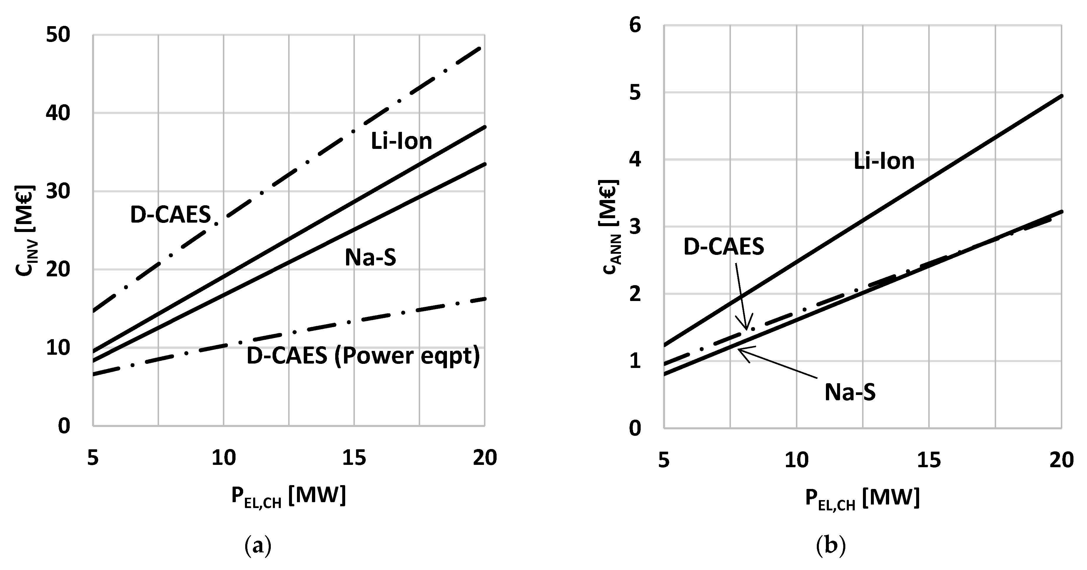
First, investment costs are analyzed and discussed. Results regarding the case tCH = tDS = 6 h are shown in Figure 2a. It can be noticed that the BES investment cost varies proportionally with PEL,CH. This is because, for a given value of tCH, the installed storage capacity of the system is proportional to PEL,CH and, consequently, Equation (3) establishes a proportional relationship between investment cost and rated power. The D-CAES investment cost curve shows instead a decreasing slope by increasing PEL,CH. This is related to the trend of power equipment investment costs, also shown in in Figure 2a. In fact, by increasing PEL,CH, the specific investment cost of those plant items whose cost depend essentially on power (i.e., the compressor train, the expander, the reversible electric machine and the heat transfer devices) tends to decrease because of the scale effect, as anticipated at the beginning of Section 2. In the present case, the power equipment cost per unit of installed power goes from 1320 €/kW for PEL,CH = 5 MW to some 800 €/kW for PEL,CH = 20 MW.
Investment costs estimated for D-CAES with artificial storage are checked against cost data given in [32], where the techno-economic performance of a comparable storage system is assessed. Such a system is designed for a charge/discharge power of 15 and 10 MW respectively, corresponding to charging/discharging periods of 5 and 9 h. Taking the uncertainty in estimating some cost items into consideration, a capital cost between 3000 €/kW (lower bound) and 4900 €/kW (upper bound) is declared (cost figures given in 2006 USD are updated to 2020 by using CEPCI and converted into euro). Based on Figure 2a and Figure 3a, capital costs evaluated for D-CAES systems range from 3000 to 4000 €/kW. Such cost figures are consistent with those provided in [32]. As a result, cost estimates provided in the present work may be considered reasonably reliable.
It can be noticed that D-CAES requires a significantly higher investment cost in respect to BES systems. Anyway, it should be considered that D-CAES systems are characterized by significantly longer lifetime than BES based ones. Therefore, the impact of investment costs on EES economic performance is better appreciated by taking the annualized capital cost, cANN, into account, i.e., the annual amount of capital required to ensure that the system under consideration may be renewed in perpetuity [46]:
c ANN = C INV i ( 1 + 1 ) T L i ( 1 + 1 ) T L 1
where i and TL indicate the annual interest rate and the lifetime of the system respectively.
Annualized capital costs versus rated charging power are plotted in Figure 2b. It can be noticed that Li-ion based systems show significant higher cANN values compared to those of Na-S and D-CAES. This is mainly due to the relatively short operational life of Li-ion batteries, being Li-ion and Na-S investment costs comparable, as can be seen in Figure 2a. The really long life duration of D-CAES systems (30 years), conversely, makes the annualized capital cost basically the same of Na-S systems, despite the noticeable investment cost difference, also evidenced in Figure 2a.
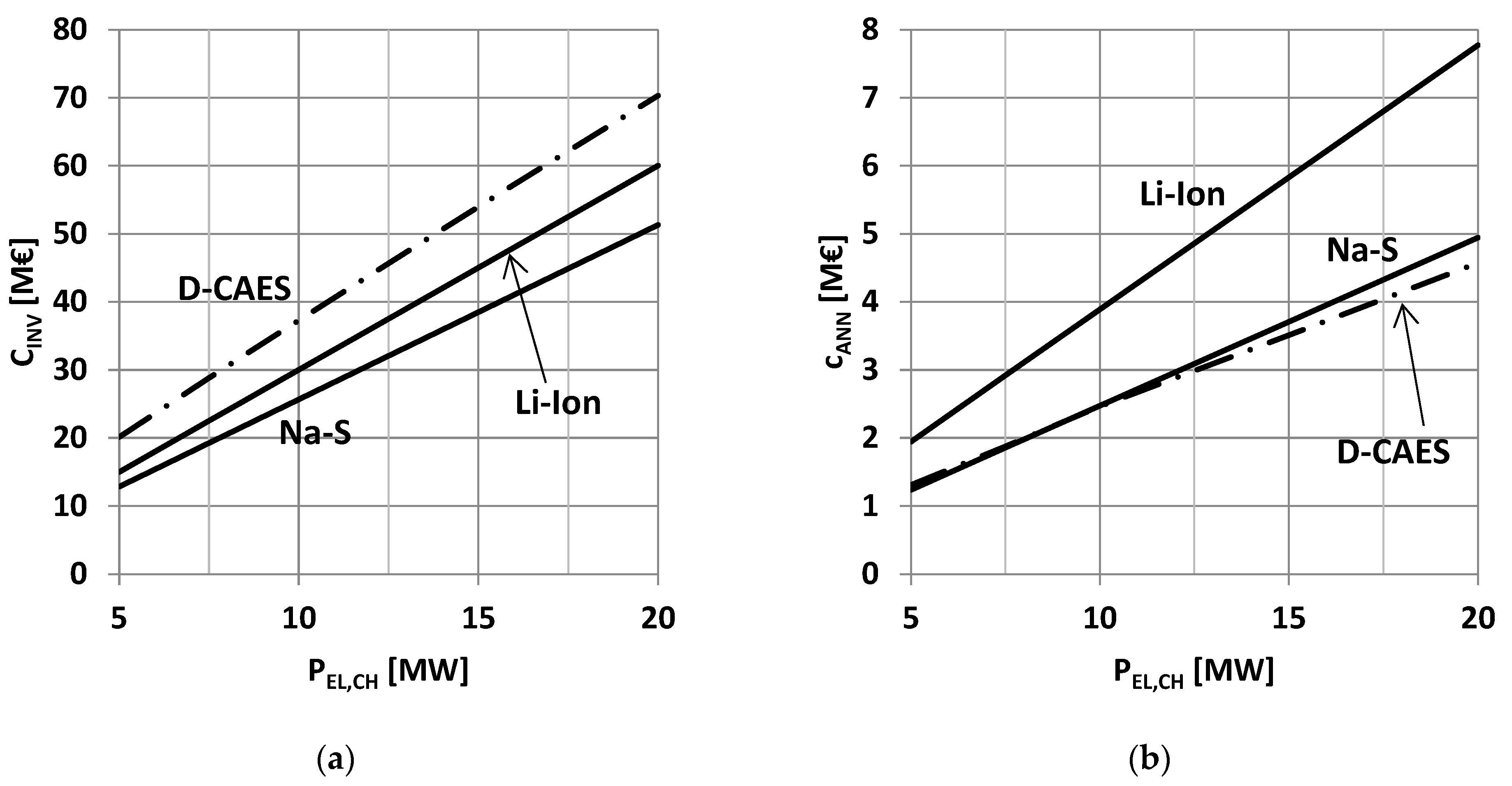
Results achieved by assuming a charge/discharge time period of 10 h are presented in Figure 3. Clearly, due to the augmented storage capacity, both investment and annualized capital cost values are higher than those presented in Figure 2. It can be seen, unlike the 6 h case, that D-CAES systems have slightly lower cANN values in comparison to Na-S based ones, as shown in Figure 3b.
Figure 4 shows the LCOS evaluated for the storage systems under comparison versus the rated power PEL,CH. Figure 4a,b refer to systems sized for charge/discharge time periods of 6 and 10 h, respectively. Curves in the upper part of both graphs refer to an electricity price of 10 €cent/kWh, while curves in the lower region are plotted by assuming a free electricity supply.
In any case, the LCOS of BES systems does not vary with the rated design power because, for a given value of the charge/discharge time period, both the numerator (i.e., the BES total cost, evaluated according to Equation (3)) and the denominator (the overall discharged electricity) of Equation (4) vary proportionally to PEL,CH. The D-CAES shows instead a decreasing LCOS trend for increasing PEL,CH values as a result of the scale effect previously discussed.
Figure 4a shows results achieved by assuming tCH = tDS = 6 h. If the electricity price is set at 10 €cent/kWh, D-CAES shows an LCOS always lower than that estimated for Li-Ion based systems. D-CAES can reach an LCOS even lower than that of Na-S based systems (0.257 €/kWh) depending on the rated power of the plant and the fuel cost. For instance, by assuming the fuel cost equal to 0.2 €/Sm3, the levelized cost of D-CAES becomes smaller than that of Na-S if the storage facility is sized for a rated power higher than 7.5 MW. If instead the fuel cost is set at 0.3 €/Sm3, the cost parity is reached for a PEL,CH value of some 13 MW.
In the case of cost-free electricity, Na-S based systems show the best LCOS. D-CAES shows a better economic performance in respect to Li-ion based systems if the rated power exceeds 6 MW and the fuel cost is set at 0.2 €/Sm3. In the case of fuel cost equal to 0.3 €/Sm3, D-CAES becomes cost-effective in respect to Li-Ion batteries if the plant rated power is higher than 10 MW
Results achieved by assuming tCH = tDS = 10 h are shown in Figure 4b. LCOS estimated for all the storage systems are, all things being equal, lower than those achieved for tCH = tDS = 6 h. In the case of an electricity price equal to 10 €cent/kWh, D-CAES prevails over Na-S if the rated power is greater than 8 MW, whatever the fuel cost. Interesting values around 0.22–0.23 €/kWh are attained for D-CAES systems sized for a rated power ranging from 15 to 20 MW. In the case of free electricity, the D-CAES levelized cost is always higher than that found for Na-S based systems (0.11 €/kWh) and lower than that evaluated for the Li-ion battery-based ones (0.15 €/kWh).
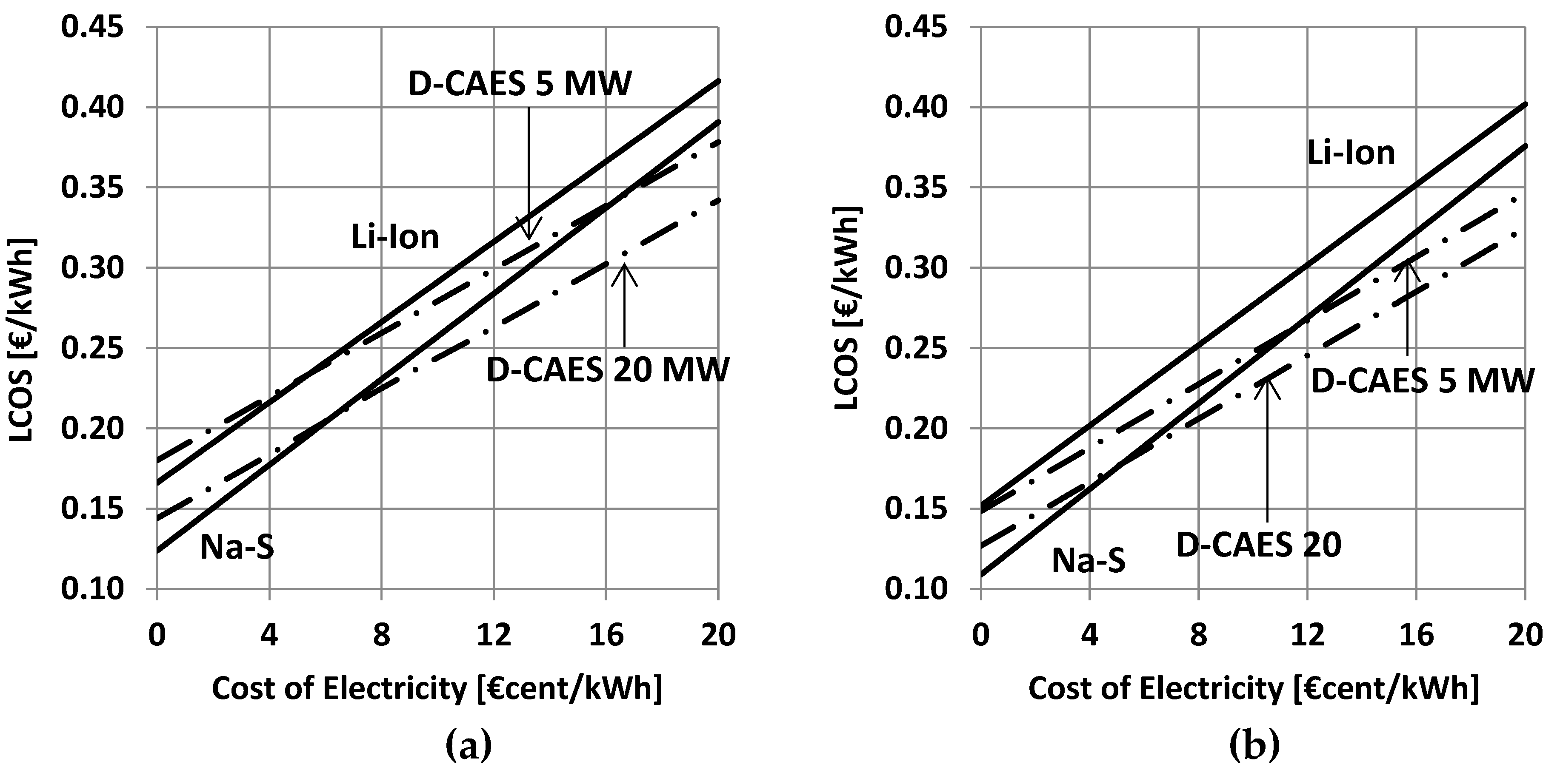
Finally, a sensitivity analysis is carried out by varying the cost of the electricity absorbed during the charging phase. As previously stated, the LCOS of BES systems does not depend on the installed power. Otherwise, the D-CAES techno-economic performance improves by increasing the system size. Therefore, LCOS curves plotted for the minimum (5 MW) and the maximum (20 MW) D-CAES installed power here considered are given. A fuel cost equal to 0.25 €/Sm3 is assumed.
A noticeable feature of D-CAES in respect to BES (already reported and commented in [43]) is the lower sensitivity to the price of electricity, evidenced by the smaller slope of LCOS lines.
The Li-ion battery-based system denotes in almost all cases the worst performance. Considering the case tCH = tDS = 6 h (Figure 5a), the 5 MW D-CAES system prevails on the Na-S one only if the cost of electricity is higher than about 16 €cent/kWh, that is an unrealistic and not cost-effective value for electric storage applications. The larger the D-CAES plant size is, the lower the cost of electricity, which makes it cheaper in respect to the Na-S system is. The 20 MW D-CAES is in fact cheaper than Na-S if the cost of the purchased electricity is higher than 8 €cent/kWh. The assumption of longer charge/discharge time periods (tCH = tDS = 10 h) makes the D-CAES system more advantageous. A LCOS lower than that of the Na-S based system is achieved if the cost of electricity is higher than 10 €cent/kWh, whatever the D-CAES plant size is. The 20 MW D-CAES plant is convenient when the cost of the kilowatt-hour is little more than 10 €cent.

4. Conclusions

An analysis aimed at exploring and comparing the techno-economic performance achievable by D-CAES with artificial storage, Na-S and Li-Ion battery-based systems has been carried out. Utility-scale storage facilities characterized by a rated power in the range of 5–20 MW and a storage capacity of tens/hundreds megawatt-hours have been addressed. Analyses have been performed by varying key quantities, such as the rated power, the storage capacity, the price of electricity absorbed from the grid during the charging phase, and the cost of fuel fed to D-CAES during the discharge phase.
Results can be summarized as follows:
  • D-CAES systems with artificial storage require investment cost significantly higher than Na-S and Li-Ion battery-based systems. Anyway, the really long lifetime of D-CAES system leads to annualized capital costs considerably lower than those of Li-ion and comparable to those evaluated for Na-S storage.
  • In all cases taken into consideration, Na-S battery-based systems show a better economic performance in comparison with Li-ion based ones.
  • The economic performance of both D-CAES and BES improves by increasing the storage capacity of the system. The D-CAES performance improvement rate, however, is higher than that estimated for BES based systems.
  • The LCOS of D-CAES systems shows a lower sensitivity to the price of electricity in respect of BES based storage facilities.
  • D-CAES based solutions can achieve a LCOS lower than that shown by Na-S batteries, provided that the size of the system and the price of electricity are large enough.

Author Contributions

Conceptualization, methodology, writing-review and editing: C.S.; methodology, validation: A.G. All authors have read and agreed to the published version of the manuscript.

Funding

This research received no external funding.

Data Availability Statement

Not applicable.

Acknowledgments

The Authors are pleased to acknowledge the University of Roma TRE for the support given to the research.

Conflicts of Interest

The authors declare no conflict of interest.

Appendix A

A short description of the D-CAES thermodynamic model developed by the authors is provided in the following.

Appendix A.1. Charge Phase Model

The model is established according to the following assumptions:
  • A perfect gas behavior is assumed for air. The isentropic exponent k (the ratio of specific heat at constant pressure to the specific heat at constant volume) is assumed equal to 1.4.
  • The N compression stages constituting the compressor train operate at constant polytropic efficiency ηPS. Moreover, it is assumed that, at any time, the N compression stages work at the same pressure ratio βS(t):
    β S ( t ) = β ( t ) N
    where β(t) is the overall pressure ratio at time t.
  • Air temperature at the exit of each intercooler and at the exit of the aftercooler is assumed to remain constant.
  • Bearing mechanical losses and losses in the reversible electric machine are taken into consideration by introducing the electric-mechanic efficiency ηEM.
  • According to [34], the stored air temperature TST is considered constant during the charging, the storage period and the discharge phase.
It is supposed that the charging phase begins when the pressure inside the reservoir is equal to pMIN and ends when the value pST is reached. Therefore, the mass of air introduced into the reservoir during the charging phase mCH can be calculated as follows:
m CH = m ST m IN = ( p ST p IN   ) V / ( RT ST )
where mST and mIN denote the mass of air contained inside the tank at the end and at the beginning of the charging phase respectively, V the storage volume, and R the air constant.
The amount of electricity required for a complete charge is calculated by combining mass and energy conservation equations written in differential form and integrating along the time. The electric energy dWEL,CH absorbed for charging the infinitesimal mass dm during the time period dt can be expressed as:
dW EL , CH = 1 η EM     R ε [ T AMB + ( N 1 ) T OUT ] × [   β ( t ) ε ( N η PS )   1 ] dm
where TAMB denotes the ambient temperature, TOUT the temperature of air exiting the intercoolers, ηEM the electric-mechanic efficiency, ηPS the stage polytropic efficiency, and ε = (k − 1)/k.
dm can be related to the pressure ratio increase dβ in the time interval dt by applying the equation of state of perfect gas:
dm = Vdp RT ST = Vp AMB RT ST × dp p AMB = p AMB V RT ST × d β
where dβ = dp/pAMB. Substituting dm into into Equation (A3) gives:
dW CH = 1 η EM   p AMB   V ε T ST [ T AMB + ( N 1 ) T OUT ] × [   β ( t ) ε ( N η PS )   1 ]   d β
The above differential equation in the only variable β can be easily integrated from βIN to βST to get the amount of electricity WEL,CH required for the full charge of the reservoir:
W EL , CH = 1 η EM p AMB V ε T ST [ T AMB + ( N 1 ) T OUT ] × [ N N + ε η PS   ( β ST ( ε N η PS + 1 ) β IN ( ε N η PS + 1 ) ) ( β ST β IN ) ]

Appendix A.2. Discharging Phase Model

Since the discharge phase is assumed to occur at rated design power, stationary plant operation can be supposed. Air and combustion products are assumed to be mixtures of thermally perfect gases. Consequently, for a given composition of the mixture, constant pressure and constant volume specific heats and thermodynamic state functions, such as enthalpy, entropy, etc., are solely dependent on temperature. Thermodynamic quantities are calculated according to [47].
The air pre-heater (APH) is modeled as a counter flow heat exchanger with a given heat tansfer effectiveness εAPH. Consequently, according to the definition of effectiveness, the air exit temperature TAPH can be calculated as:
T APH = ε APH ( T GE , OUT T ST ) + T ST
Representing TST and TGE,OUT the air and the exhaust gas inlet temperatures, as shown in Figure 1b.
The specific enthalpy of combustion gas entering the gas expander (GE) hGE,IN is evaluated by applying the energy conservation equation to the combustion chamber (CC). According to Figure 1, we get:
h GE , IN = α α + 1   ( 1 α H L η CC +   h APT )
where α denotes the air to fuel ratio, HL the fuel lower heating value, ηCC the CC efficiency (accounting for imperfect combustion and insulation losses), and hAPT the air specific enthalpy evaluated at temperature TAPH.
The gas expander (GE) is modeled by adopting a polytropic expansion process. The temperature of the flue gas TGE,OUT is calculated as follows:
T GE , OUT =   T GE , IN   ( 1 β IN ε G η PE )
where βIN denotes the ratio between GE inlet and outlet pressures, ηPE the polytropic expansion efficiency, and εG the isentropic exponent of the combustion gas. The knowledge of TGE,OUT allows the calculation of the gas enthalpy hGE,OUT, and, finally, the overall electricity generated during the discharge phase:
W EL , DS = η ME α + 1 α   ( h GE , IN h GE , OUT )   m CH

References

  1. Xing, L.; Wang, J.; Dooner, M.; Clark, J. Overview of current development in electrical energy storage technologies and the application potential in power system operation. Appl. Energy 2015, 137, 511–536. [Google Scholar]
  2. May, G.J.; Davidson, A.; Mohanov, B. Lead batteries for utility energy storage: A review. J. Energy Storage 2018, 15, 145–157. [Google Scholar] [CrossRef]
  3. Rossi, A.; Stabile, M.; Puglisi, C.; Fabretti, D.; Merlo, M. Evaluation of the energy storage system Impact on the Italian ancillary market. Sustain. Energy Grid Netw. 2019, 18, 100178. [Google Scholar] [CrossRef]
  4. Guittet, M.; Capezzali, M.; Gaudard, L.; Romerio, F.; Vuille, F.; Avellan, F. Study of the drivers and asset management of pumped-storage power plants historical and geographical perspective. Energy 2016, 111, 560–579. [Google Scholar] [CrossRef]
  5. Blakers, A.; Stocks, M.; Lu, B.; Cheng, C. A review of pumped hydro energy storage. Prog. Energy 2021, 3, 022003. [Google Scholar] [CrossRef]
  6. TERNA. Report di Esercizio I Anno di Sperimentazione. Sperimentazione di Progetti Pilota di Accumulo Energetico a Batterie di Tipo Energy Intensiv. Available online: http://download.terna.it/terna/0000/0934/81.PDF (accessed on 27 May 2021).
  7. IRENA. Utility-Scale Batteries. Innovation Landscape Brief. Available online: https://www.irena.org/-/media/Files/IRENA/Agency/Publication/2019/Sep/IRENA_Utility-scale-batteries_2019.pdf (accessed on 10 June 2022).
  8. Goldman, S. SDG&E and AES Energy Storage Unveil World’s Largest Lithium Ion Battery-Based Energy Storage Installation. Available online: https://blog.fluenceenergy.com/sdge-and-aes-energy-storage-unveil-worlds-largest-battery-storage-installation (accessed on 10 June 2022).
  9. Brakels, R. Tesla Big Battery First Year: Lowers Electricity Prices, Makes Money, Is Not on Fire. Available online: https://www.solarquotes.com.au/blog/tesla-big-battery-first-year/ (accessed on 10 June 2022).
  10. Csereklyei, Z.; Kallies, A.; Diaz Valdivia, A. The status of and opportunities for utility-scale battery storage in Australia: A regulatory and market perspective. Util. Policy 2021, 73, 101313. [Google Scholar] [CrossRef]
  11. Zakeri, B.; Syri, S. Electrical energy storage systems: A comparative life cycle cost analysis. Renew. Sustain. Energy Rev. 2015, 42, 569–596. [Google Scholar] [CrossRef]
  12. Moustafa, M.G.; Sanad, M.M.S. Green fabrication of ZnAl2O4-coated LiFePO4 nanoparticles for enhanced electrochemical performance in Li-ion batteries. J. Alloys Compd. 2022, 903, 163910. [Google Scholar] [CrossRef]
  13. Sanad, M.M.S.; Azab, A.A.; Taha, T.A. Inducing lattice defects in calcium ferrite anode materials for improved electrochemical performance in lithium-ion batteries. Ceram. Int. 2022, 48, 12537–12548. [Google Scholar] [CrossRef]
  14. Mostafa, H.M.; Abdel Aleem, S.H.E.; Ali, S.G.; Ali, Z.M. Techno-economic assessment of energy storage systems using annualized life cycle cost storage (LCCOS) and levelized cost of energy (LCOE) metrics. J. Energy Storage 2020, 29, 101245. [Google Scholar] [CrossRef]
  15. Alotto, P.; Guarnieri, M.; Moro, F. Redox flow batteries for the storage of renewable energy: A review. Renew. Sustain. Energy Rev. 2014, 29, 325–335. [Google Scholar] [CrossRef]
  16. Colthorpe, A. First Phase of 800 MWh World Biggest Flow Battery Commissioned in China. Available online: https://www.energy-storage.news/first-phase-of-800mwh-world-biggest-flow-battery-commissioned-in-china/ (accessed on 21 August 2022).
  17. Rahman, M.M.; Oni, A.O.; Gemechu, E.; Kumar, A. Assessment of energy storage technologies: A review. Energy Convers. Manag. 2020, 223, 113295. [Google Scholar] [CrossRef]
  18. Darling, R.M. Techno-economic analyses of several redox flow batteries using levelized cost of energy storage. Curr. Opin. Chem. Eng. 2022, 37, 100855. [Google Scholar] [CrossRef]
  19. Rahman, M.M.; Oni, A.O.; Gemechu, E.; Kumar, A. The development of techno-economic models for the assessment of utility-scale electro-chemical battery storage systems. Appl. Energy 2021, 283, 116343. [Google Scholar] [CrossRef]
  20. Kim, Y.M.; Lee, J.H.; Kim, S.J.; Favrat, D. Potential and Evolution of Compressed Air Energy Storage: Energy and Exergy Analyses. Entropy 2012, 14, 1501–1521. [Google Scholar] [CrossRef]
  21. Budt, M.; Wolf, D.; Span, R.; Yan, J. A review on compressed air energy storage: Basic principles. Past milestones and recent developments. Appl. Energy 2016, 170, 250–268. [Google Scholar] [CrossRef]
  22. Chen, L.; Hu, P.; Sheng, C.; Xie, M. A Novel Compressed Air Energy Storage (CAES) Combined with Pre-Cooler and Using Low Grade Waste Heat as Heat Source. Energy 2017, 131, 259–266. [Google Scholar] [CrossRef]
  23. Li, Y.; Sciacovelli, A.; Peng, X.; Radcliffe, J.; Ding, Y. Integrating Compressed Air Energy Storage with a Diesel Engine for Electricity Generation in Isolated Areas. Appl. Energy 2016, 171, 26–36. [Google Scholar] [CrossRef]
  24. Salvini, C. Techno-Economic Analysis of CAES Systems Integrated into Gas-Steam Combined Plants. Energy Procedia 2016, 101, 870–877. [Google Scholar] [CrossRef]
  25. Salvini, C. Performance assessment of a CAES system integrated into a gas-steam combined plant. Energy Procedia 2017, 136, 264–269. [Google Scholar] [CrossRef]
  26. Crotogino, F.; Mohmeyer, K.U.; Scharf, R. Huntorf CAES: More than 20 Years of Successful Operation. In Proceedings of the Spring 2001 Meeting, Orlando, FL, USA, 15–18 April 2001. [Google Scholar]
  27. King, M.; Jain, A.; Bhakar, R.; Mathur, J.; Wang, J. Overview of Current Compressed Air Energy Storage Projects and Analysis of the Potential Underground Storage Capacity in India and the UK. Renew. Sustain. Energy Rev. 2021, 139, 110705. [Google Scholar] [CrossRef]
  28. Salvini, C.; Giovannelli, A. Techno-economic comparison of diabatic CAES with artificial air reservoir and battery energy storage systems. Energy Rep. 2022, 8, 601–607. [Google Scholar] [CrossRef]
  29. Salvini, C.; Giovannelli, A.; Sabatello, D. Analysis of diabatic compressed air energy storage systems with artificial reservoir using the levelized cost of storage method. Int. J. Energy Res. 2021, 45, 254–268. [Google Scholar] [CrossRef]
  30. Douglas, L.E. Industrial Chemical Process Design, 2nd ed.; McGraw-Hill: New York, NY, USA, 2014. [Google Scholar]
  31. Pedrick, J.; Marean, J.B. Compressed Air Energy Storage Engineering and Economic Study, Final Report, Nyserda Report 10-09, December 2009; NYSERDA: Albany, NY, USA, 2009. [Google Scholar]
  32. Sayer, J.; Pemberton, D.; Jewitt, J.; Pletka, R.; Fishbach, M.; Meyer, T.; Ward, M.; Bjorge, B.; Hargreaves, D.; Jordan, G. Mini-Compressed Air Energy Storage for Transmission and Congestion Relief and Wind Shaping Application, Final Report, Nyserda, Report 08-5, July 2008; NYSERDA: Albany, NY, USA, 2008. [Google Scholar]
  33. Liu, X.; Zhang, Z.; Xu, Y.; Chen, H.; Chen, Z.; Tan, C. Economic analysis of using above ground gas storage device for compressed air storage systems. J. Therm. Sci. 2014, 6, 535–543. [Google Scholar] [CrossRef]
  34. Salvini, C. Performance Analysis of Small Size Compressed Air Energy Storage Systems for Power Augmentation: Air Injection and Air Injection/Expander Schemes. Heat Transf. Eng. 2018, 39, 304–315. [Google Scholar] [CrossRef]
  35. Lincoln Electric, Welding Pressure Pipelines & Piping Systems—Procedures and Techniques. Available online: http://www.lincolnelectric.com/assets/global/Products/Consumable_PipelinerConsumables-Pipeliner-PipelinerLH-D90/c2420.pdf (accessed on 21 August 2022).
  36. Cerri, G.; Mazzoni, S.; Salvini, C. Steam cycle simulator for CHP plants”. In Proceedings of the ASME Turbo Expo, San Antonio, TX, USA, 3–7 June 2013. [Google Scholar] [CrossRef]
  37. Cerri, G.; Gazzino, M.; Botta, F.; Salvini, C. Production planning with hot section life prediction for optimum gas turbine management. Int. J. Gas Turbine Propuls. Power Syst. 2008, 2, 9–16. [Google Scholar] [CrossRef]
  38. Salvini, C. CAES systems integrated into gas-steam combined plant: Design point performance assessment. Energies 2018, 11, 415. [Google Scholar] [CrossRef]
  39. Foster-Pegg, R.W. Capital Cost of Gas-Turbine Heat Recovery Boilers. Chem. Eng. 1989, 14, 73–78. [Google Scholar]
  40. Salvini, C.; Giovannelli, A.; Varano, M. Economic Analysis of Small Size Gas Turbine Based CHP Plants in the Present Italian Context. Int. J. Heat Technol. 2016, 34, S443–S450. [Google Scholar] [CrossRef]
  41. PacifiCorp. Battery Energy Storage for the 2017 IRP. 2016. Available online: http://www.pacificorp.com/content/dam/pacificorp/doc/Energy_Sources/Integrated_Resource_Plan/2017_IRP/10018304_R-01-D_PacifiCorp_Battery_Energy_Storage_Study.pdf (accessed on 21 March 2019).
  42. Rahmann, C.; Mac-Clure, B.; Vittal, V.; Valencia, F. Break-Even Points of Battery Energy Storage Systems for Peak Shaving applications. Energies 2017, 10, 833. [Google Scholar] [CrossRef]
  43. Julch, V. Comparison of electricity storage options using levelized cost of storage (LCOS) method. Appl. Energy 2016, 183, 1594–1606. [Google Scholar] [CrossRef]
  44. Tesla Battery Cost Revealed Two Years after Blackout. Available online: https://www.abc.net.au/news/2018-09-27/tesla-battery-cost-revealed-two-years-after-blackout/10310680 (accessed on 30 June 2022).
  45. Cole, W.; Frazier, W. Cost Projection for Utility-Scale Battery Storage: 2020 Update. Available online: https://www.nrel.gov/docs/fy20osti/75385.pdf (accessed on 28 May 2021).
  46. Perry, H.; Green, D.W. Perry’s Chemical Engineers’ Handbook, 7th ed.; McGraw Hill: New York, NY, USA, 1998. [Google Scholar]
  47. Rivkin, S.L. Thermodynamic Properties of Gases; Springer: Berlin/Heidelberg, Germany, 1988. [Google Scholar]
Figure 1. Proposed D-CAES system: (a) Plant lay out; (b) Representation on a T-s diagram of processes occurring in the D-CAES plant under consideration.
Energies 15 06644 g001
Figure 2. Investment expenditure by varying the rated charging power for storage systems under comparison. Case tCH = tDS = 6 h: (a) Investment cost; (b) Annualized capital cost.
Energies 15 06644 g002
Figure 3. Investment expenditure by varying the rated charging power for storage systems under comparison. Case tCH = tDS = 10 h: (a) Investment cost; (b) Annualized capital cost.
Energies 15 06644 g003
Figure 4. LCOS by varying the rated charging power of storage systems under comparison: (a) Case tCH = tDS = 6 h; (b) Case tCH = tDS = 10 h.
Energies 15 06644 g004
Figure 5. LCOS by varying the cost of electricity absorbed during the charging phase: (a) Case tCH = tDS = 6 h; (b) Case tCH = tDS = 10 h.
Energies 15 06644 g005
Table 1. Main Assumption for D-CAES thermodynamic analysis.
Ambient Temperature TAMB [°C]20
Ambient Pressure pAMB [kPa]100
Intercoolers/Aftercooler Outlet Temp. [°C]35
Compression Polytropic Efficiency [%]85
Mechanical-Electrical Efficiency [%]97
Stored Air Temperature [°C]30
Storage pressure [bar]100
Natural Gas Lower Heating Value [MJ/kg]50
Combustion Chamber Efficiency [%]99
Air Pre-Heater Effectiveness [%]90
Gas Expander inlet pressure [bar]20
Gas Expander inlet temperature [°C]700
Air Expander Polytropic Efficiency [%]85
Table 2. Data assumed for techno-economic BES model.
BES TypeNa-SLi-Ion
Technical data
Efficiency [%]7580
Deep of Discharge DOD [%]8080
Life Duration [years]1510
Investment cost data
CPOWER [€/kW]350250
CSTORAGE [€/kWh]240250
Maintenance cost data
CM [€/kW/year]2625
Publisher’s Note: MDPI stays neutral with regard to jurisdictional claims in published maps and institutional affiliations.