Abstract
The paper discusses the problem of cooperation between multiple model predictive control (MPC) systems. This approach aims at improving the control quality in electrical energy generation and forms the next step in a series of publications by the authors focusing on the optimization and control of electric power systems. Cooperation and cooperative object concepts in relation to a multi MPC system are defined and a cooperative control solution for a nuclear power plant’s turbine generator set is proposed. The aim of enabling information exchange between the controllers is to improve the performance of power generation. Presented and discussed simulation tests include various variants of information exchange between the turbine and synchronous generator MPC controllers of the nuclear power plant.
1. Introduction
Preliminaries
The paper presents the results of research on the cooperation of MPC predictive control systems. This is the next stage in a series of studies focusing on optimization and control of electric power systems discussing various aspects of model predictive control (MPC) in a nuclear power plant’s turbine generator control system. A turbine and generator set of a nuclear power plant with their control systems was selected as the research object. This is to facilitate the synthesis of better control systems and improvement of the quality of control in the power industry in the face of challenges related to the changing nature of the energy sector, i.e., the growth of renewable energy generation. This paper is the fifth in a series related to the performance of energy generation. In the first paper [1], the first approach to a distributed control with information exchange was made, secondly, publication [2] discussed the robustness of the distributed MPC control of a turbine generator set, thirdly, in [3], the authors analyzed the possibility of extending the MPC generator predictive control system with the functionality of a power system stabilizer, and finally, in [4], the authors develop integral quality indicators for the evaluation of the quality of the turbine generator control system. Due to the observed shortages in the past approaches, which did not fully exploit the possibility to use cross-communication between the controllers, an in-depth set of simulation tests has been carried out and the results are reported in the current paper.
As stated in the original version of the paper, the results are indeed simulation based, due to the reasons connected to process safety. Nevertheless, the model of the turbine has been obtained from [5], and verified with the results obtained by the other research group on the basis of the other source data for the same turbine type [6] and parameterized in accordance to the requirements stated in the first Polish nuclear program [7]. A model GTHW-600 generator has been developed on the basis of [8] in cooperation with energy generation groups, experienced in modeling the GTHW-360 generator. The presented results form a potential research topic for further verification of the obtained results with a real turbine and a generator.
The authors first define the concepts of cooperation and cooperative object, and then present how this theory applies to the discussed control system in a nuclear power plant. The paper proposes the use of an applicable mechanism of cooperation between the turbine and generator control systems, which allows them to meet the real-time conditions and ensure the safe, reliable, and stable operation of the whole system. When the optimization problem is not feasible, the output-related constraints are reverted to create a penalizing term and form soft constraints. It is necessary to define the manner of cooperation and to define the principles of cooperation of objects that have a purpose other than joint movement in space. To do this, first of all, it is necessary to determine what features the members of the group of cooperating controllers have, as well as how their cooperation is understood. For the purpose of the paper, it was found advantageous to adopt the definition of cooperation presented in the documents developed under the European project CONET (Cooperating Objects NETwork of excellence) [9].
It is assumed that the use of the currently available possibilities of industrial communication networks in order to increase the degree of information exchanged between the control systems may improve the quality of control by exchanging information without creating communication bottlenecks. The turbine generator set system allows for a substantial analysis of the possibilities offered by the information exchange due to the fact that the connection of components with one shaft leads to their mutual interaction. Accordingly, the turbine controller and the generator controller are, in a sense, in competition with each other in trying to achieve different goals. The purpose of the turbine controller is to follow the power setpoint as quickly as possible, which causes voltage amplitude and rotational speed (frequency) oscillations to occur, while the generator controller (excitation controller) tries to stabilize the voltage at the setpoint. Since these actions are contradictory, it seems that the addition of a communication layer between the controllers determining the successive values of the control signals may improve the quality of the control of the system as a whole. For this purpose, it is proposed to replace the commonly used turbine and generator control systems with MPC controllers. This technology allows for the determination of successive values of the control signal based on the object model and the prediction of its future behavior. It was decided to take the existence of the second part of the system in each of the controllers into account (each controller has a model of the whole system) and to add the possibility of communication between them. The knowledge concerning the model of the system parameters is obtained by using recursive estimation techniques. Thanks to this, each of the control systems can take information from the partner into account while predicting the behavior of the entire turbine generator set in the future while calculating the value of the next control signal. In this particular case, it was decided to exchange only information on the current activities of the other controller. Possibilities for the exchange of other information or a broader set of information may be the subject of further research (e.g., exchange of information on entire trajectories of control signals). The turbine set control systems influence each other’s work through a strong interaction of the control objects (turbine and generator), but they do not exchange any information directly. The voltage stabilization system disturbs the generator’s electromagnetic moment, which leads to disturbances in the rotational speed and, consequently, to disturbances in the active power output by the generator. The disturbances of the rotational speed of the generator shaft, caused by the change of opening degree of the control valve during the power change, lead to disturbances that cause the generator voltage oscillation. Therefore, in order to compensate for the undesirable effects of mutual interaction in the facility, the paper proposes expanding the turbo set control system with a mechanism to prevent them. The implementation of this task is possible in several ways, such as the use of a common central controller looking for the optimal control signal for both the turbine and the generator, extending the control systems with additional interference measurement capabilities, or adding the information exchange path between individual control systems. In this case, it was decided to use cooperative control technology. Currently, a number of studies are carried out on systems of this type, i.e., distributed, cooperative and multi-agent control. In [9], the authors describe the idea of cooperative objects, cooperative control of multi-agent systems is discussed in [10], while the author of [11] analyzes distributed system with cooperation. In those three publications, the idea of multi-agent systems with cooperation between the distributed components is presented. This approach is quite general. As presented in the paper, the solution uses two MPC model predictive controllers with cooperation and can be categorized as a distributed MPC system. The authors of [12] discuss the theory and applications of distributed MPC controllers, and the authors [13] provide a solid introduction to the topic of the MPC idea. The authors of [14] analyze immeasurable states and uncertain parameters in the case of a distributed MPC for linear systems. The authors of [15,16] focus on stability and feasibility of such distributed control systems. This is motivated by the observation of cooperation among humans, as well as in the animal world, through the prism of the benefits that this cooperation brings, see for example [17]. Birds, groups of animals, and schools of fish move as one whole, even though their movement is the result of the movement of many independent units. Synchronized movement and choreographic behavior of groups based on the decisions of individuals [10] is an inspiration to find a mechanism for cooperation between control systems. The current state of the art in the field of communication allows for the exchange of information between devices e.g., the Internet of Things (IoT), and the implementation of cooperative systems in practice. In [18], the author analyzed the way in which individual members of groups of animals cooperate with each other and presented a set of simple rules that govern individual units, i.e., collision avoidance (avoid collisions with neighboring units), matching speed (move at the same speed as the n/us), and herd centering (stay close to the n/us). These include the Bat Algorithm, the Shuffle Frog Leap Algorithm, Water Wave-like Optimization, Grey Wolf optimizer, Spider Monkey Optimization, Gorilla Troop optimizer, Cuckoo search, and others [19]. The above shows clearly that the seemingly complex mechanisms of cooperation of large groups of animals can be described in the form of a set of simple rules. This comparison is most often used in the case of the task of coordinating the movement of groups of vehicles or robots. In such a case, the principles presented by Reynolds can be directly applied to the movement of objects in space.
In the case of a turbine generator set, it is not about a coordinated movement of objects in space, but rather the cooperation of control systems. Therefore, other principles and mechanisms of cooperation must be defined. The purpose of this research is to define these principles and to identify the advantageous configuration. Therefore, the main novelty of the solution presented in the paper is the replacement of the system comprising two independent control systems, with a system of a cooperating pair of MPC controllers exchanging information with each other and the creation of the system of MPC cooperation principles in a nuclear power plant.
As for the MPC application in power systems, a number of studies have been carried out, considering both renewable energy sources (RES) and thermal power plants. Thus, the current development of renewable energy sources forces MPC control techniques implementation on power system units such as coal or nuclear power plants. In [20], the authors presented the cooperative distributed MPC application in wind farm operation, where the active power output has been controlled, regarding the mechanical structure fatigue reduction. The authors compared MPC performance results for hard and soft constraints, i.e. farm-wide power output. The obtained results show the advantages of cooperative distributed MPC performance. On the other hand, in [21] the authors presented the problem of a complex energy system, exposed to numerous disturbances on the example of a microgrid including RES, combined heating and power plants, and energy storage systems. The authors proposed an improvement of deterministic MPC with robust MPC, which could be able to deal with uncertainties in the system model both regarding electrical and thermal loads. When it comes to large-scale power networks, another approach was presented in [22], where the authors proposed Lagrange-based distributed MPC. The authors highlighted the strengths of distributed MPC for complex power systems, as well as MPC’s applicability in microgrids, bearing in mind that even with a strong share of RES, conventional and nuclear power plants will still be responsible for generating electricity when RES is not available.
The main contribution of this work is the presentation of the basis for the multi-agent MPC predictive control system based on the communication of many controllers in order to achieve a common goal. The presented considerations cover only a system of two controllers, but it builds the principles of distributed multi-agent control in a nuclear power plant. Despite the fact that in the literature one can find a description of many solutions of distributed control in multi-agent systems (e.g., review of solutions in [11]), this approach offers new insight into the cooperation task in a nuclear power plant’s turbine generator set, which has not been analyzed from this viewpoint before.
The paper is structured as follows: Section 2 describes the turbine generator set control problem which is the basis for further considerations, Section 3 discusses the definition of cooperation and presents the proposed solution, and Section 4 presents simulation results of system simulation for various variants of information exchange. The paper ends with a summary containing conclusions resulting from the conducted research and directions for further research. In order to streamline the presentation of performance requirements, the nomenclature used in the paper is presented below.
2. Problem Description
As a standard, the control system of the turbine generator set consists of two independent control loops (turbine’s controller and generator’s controller), sometimes extended with a power system stabilizer (additional feedback loop used to minimize the oscillations of the active power). In this classical approach, the controllers do not exchange any information with each other and the only interaction between them is through exerting actions over a common control plant (turbine generator set based on a common shaft). It is assumed that adding some degree of additional communication and using it by including it in the calculation of the control signal will improve the quality of the control, which is a major novelty at the current stage of our research. In the article, it is proposed to include an additional piece of information to be exchanged between the controllers in order to ensure interaction at the control layer, as is observed here at the level of the plant (i.e., inherent internal interaction between the turbine and the generator). This additional information exchange aims to further improve the quality of the control. The information concerning a choice of a controller, control system of a turbine generator set, selected model of the above-mentioned set, and MPC approach preliminaries to the topic is presented in [2,3,4] and is not cited here for the sake of brevity and to avoid unnecessary repetitions.
In this paper, only linear control algorithms are used to carry out the above-mentioned tasks, while the authors of [23] further investigate the possibilities of using non-linear MPC for energy management. Taking a similar approach could be the next step of research in improving the solution presented in this paper in the future. In order to design a control loop of a turbine set, its model had to be formulated first, see Figure 1, with the inputs of the form: as the degree of the opening of the inlet valve, as the excitation voltage of the generator, the outputs as / generator’s voltage and power, and Q as the thermal load which can be considered as an exogenous signal, rejecting a proper action of the control loop. The above gives rise to a natural model taking the following natural flows of the listed signals: , , and .
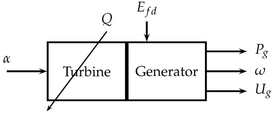
Figure 1.
Inputs and outputs of the model.
The traditional PI controller-based control loop has been outlined in Section 2, whereas the core idea in the current paper is to use the quadratic dynamic matrix control (QDMC) version of the model predictive controller in order to take advantages of optimal control actions, as reported in [3], where such an approach is used to synthesize an MPC controller of a generator including the functionality of a power system stabilizer. Contrary to the previous research stage, in this case, some snippet of information is exchanged between the MPC-like controller and the outer control loops, which is implemented by the introduction of exogenous inputs such as (rotational speed), (active power), or (steam turbine’s control valve opening degree), or in the adaptive approach, using the RLS identification scheme.
It is to be clearly stated that such an approach is very different from the traditional one, and it is not commonly met in power generation control loops, as it replaces a safe choice of the proportional plus integral plus derivative controller [3]. The predictive-control related approach allows one to include constraints into the optimization problem, related to the process or to other requirements [24], still enabling one to obtain the optimal choice of the control signal, and preserving the possibility to re-tune the controller by changing prediction horizons or changing the weights in the performance index to mimic the perfect operation of the control loop expressed by a proper choice of the performance index. The control loop block diagram of the quadratic dynamic matrix controller with adaptation feature is given in Figure 2.
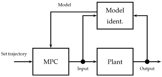
Figure 2.
Structure of an MPC controller with online model identification.
As this research study relates to the classical MPC controller, a short review will be presented below, taken from the previous publications [2,3,4]. The predictive controller requires information concerning free and forced response parts for a system with s inputs and r outputs, and:
where the number of the sample is given as k, and the future one step ahead value is obtained on the basis of availability of the information at sample k and denoted by . The set of m control values for each of s inputs forms the following vector
Any further information concerning the structure of the controller, methodology to fine-tune weights in the performance index, and the impact of the other parameters is given in [1]. The optimization problem solved for every k is given as
with the control vector calculated on the basis of the control update and its prior value, weighting matrix and a soft constraint term defined by . The outputs of the model in the form of the power, voltage, and frequency of the generator give ; reference power, constant set voltage, and set frequency form the reference vector , opening control valve value, and excitation voltage are control signal components ; finally, valve opening and excitation system voltage constraints result in natural bounds on , . The QMDC problem is solved to obtain the optimal control update, fed the plant in an RH fashion.
The necessary calculations have been performed on a GHz PC with 16 GB of memory, and each solution to the QDMC problem has been obtained in . This potential bottleneck can be avoided in the industry by using modern solvers and fast industrial PCs to solve QP problems in a time comparable to the ones mentioned above. This is given rise by rapid changes in states of the considered electrical machine. Further reduction in calculation times can be obtained by using an analytical solution to the MPC problem at the cost of exchanging hard into soft constraints using penalizing terms. The remaining calculations related to model identification or communication across control systems can be done in parallel with virtually no computational cost.
3. Model and Methods
In the case of direct communication, information can be exchanged in various ways, using various transmission media, and also relate to the exchange of information between individual objects and their entire groups. In addition, the content of the information exchanged may also differ: from information about the state of the object, through planned activities (single step, entire trajectory), to joint planning of further activities. The second and third cases—indirect communication—can be used when there are no direct interfaces for direct information exchange between objects [9]. In classic solutions and in the considered control systems without cooperation (e.g., fuzzy [25,26] and gain-scheduling [27] solutions researched before by the authors), the turbine and generator control systems communicate indirectly in the third of the above-mentioned ways, that is, by measuring the interference caused by the interaction of the other system. It is possible to select the parameters of the controllers so that they are able to compensate for disturbances resulting from this interaction. It was decided to expand the possibilities of information exchange and add an additional direct communication path. As a result, it is possible to transmit information about the mutual influence on the control object even before measurable disturbances occur. This type of approach should minimize the negative impact of the interaction between the turbine and generator, leading to the deterioration of the quality of electricity.
A separate issue is a formulation of what information should be sent between controllers. The different content of the messages was considered: informing about the state of the object, about the developed control signal (actions taken by the control system), about the developed work trajectory (actions the control system is about to take), or common reconciliation of the trajectory of control signals. After analyzing the above options, it was decided to use the second solution, i.e., to exchange only the currently developed control signal value. To take full advantage of the state information, it would be necessary to have exactly the same plant model, which would give the possibility to compute the appropriate outputs or use that data for prediction purposes. Secondly, although the information about the trajectory at first glance seems to be more complete information, in the proposed solution, due to the non-linearity of the plant, the control horizon was assumed to be 1, which means that only one control signal value is computed in each step and is held over the entire prediction horizon. In such a case, the knowledge of this value is sufficient to predict the behavior of the object in subsequent moments. Communication between the controllers takes place at every control step, so the information about any change in the control signal is immediately available. Finally, the common negotiation of the trajectory could lead to additional benefits, however, it requires more resources and, in its simplest form, makes it difficult to maintain the autonomy and modularity of the solution—controllers become strongly dependent on each other. Due to the above, it was decided to exchange only information about the developed control signal in the form of a single value calculated at the current discrete time instant. This approach has a number of advantages in the context of a distributed cooperative control system:
- 1.
- Each of the controllers informs the other systems about the generated control signal. The information is available for all controllers of adjacent control systems (currently only the turbine and generator controllers pair is considered). This type of communication—information broadcasting—in no way adversely affects the operation of the controller that provides this information.
- 2.
- Each controller can use the information available from neighboring systems. This information is used voluntarily, i.e., it can be used for any purpose or not used at all. This assumption allows for the preservation of full modularity and autonomy of individual systems. A cooperative controller can be replaced by another one that uses the information in a different way or does not use it at all. This also affects the solution’s expandability. Each subsequent module can use the information already provided by the existing modules. This type of extension does not require changes to the existing control system (thanks to the modularity, it is also possible to replace the existing elements with those that will take into account new information).
- 3.
- In the proposed solution, each of the QDMC controllers has a control object model identified at each step of the algorithm, which takes into account the influence of additional variables on the controlled outputs. Thanks to this, it can have information about the plant (structure fragment and parameters) that is unavailable for other systems. For example, in the case of such a distributed structure, the turbine control system does not need to have full information about the effect of the change of control valve opening on the generator voltage—this part of the prediction is performed by the generator controller on the basis of the valve opening information.
- 4.
- As mentioned above, due to the non-linear nature of the plant, the control step is assumed to be one, and communication takes place in each control step. This means that despite the exchange of only one value, both controllers have the same knowledge about future controls (which will be held constant on the prediction horizon).
- 5.
- Using only a single value also reduces the amount of data transferred between systems and the complexity of the solved optimization task at each discrete time instant. In the era of modern industrial communication systems, the mere transfer of more data is not a problem, however, it affects the complexity of the algorithms that must take these data into account and analyze them.
- 6.
- By sending the information about the control signal it is possible to predict (thanks to the possessed object model) the influence of such control on the object before the disturbance finally occurs. Thanks to this, it is possible to quickly compensate for disturbances, and thus minimize them.
In the case under consideration, the main goal of the turbine set control system is to minimize the oscillation of the voltage amplitude and frequency while keeping up with the demand for electric and thermal power. Such a goal was imposed a priori based on the requirements to be met by this type of control system. For the needs of the control system analysis, in the case of the considered cooperative object, a bottom-up concept was adopted, i.e. by defining the goals for individual subsystems of the cooperative object, a common goal of the whole was derived as a result.
In the discussed case of the turbine set control system, turbine and generator control systems have their own independent goals, which make up the common goal of the turbine set control system. The task of the turbine control system is to follow the power demand (electric and thermal), and the task of the generator control system is to stabilize the voltage at a given level. As mentioned, these tasks are to some extent contradictory (internal dependencies lead to the formation of undesirable effects), but thanks to the exchange of information, each of the systems can react early enough to minimize possible disturbances. Thus, looking at the control system of the turbine set as a whole (cooperative object), a common goal can be formulated for it, consisting in keeping up with the electric and thermal power demand while stabilizing the voltage and minimizing disturbances (negative impact on the amplitude and frequency of the voltage) resulting from the internal dependencies of the turbine and the generator.
In the discussed case, there are two systems with different possibilities of influencing the environment (control of the control valve opening degree and the excitation voltage), which alone cannot achieve the assumed goal of controlling the turbine generator set. The agents may cooperate to varying degrees in order to achieve a common goal (or not at all), but they must work simultaneously in order to accomplish the task. In this sense, each controller is responsible for its own part of solving the problem.
In the considered example of the control system of the turbine generator set, the interaction of the turbine generator set elements is an example of competition. The turbine and generator elements interact with each other through interrelationships, which interfere with each other’s operation. An attempt to follow the set power more precisely leads to disturbances in the voltage waveform, and stronger voltage stabilization leads to disturbances in the turbine rotational speed, and thus in power. These impacts are known and acceptable, but undesirable as they lead to a deterioration of the quality of the electricity. In practice, additional solutions are used, such as a system stabilizer, which, by adding additional control loops, allows us to reduce the occurrence of interference.
By analyzing the effects caused by the operation of the second control system, it is possible to track how it affects the system (this is an example of indirect communication between control systems), however, this information is available too late, i.e., when the disturbance has already occurred. The solution is to add an additional direct information exchange track. In such a situation, the interaction between the control systems takes on the character of coopetition (cooperation and competition at the same time), i.e., controllers cooperate by exchanging information with each other, while disrupting their work while pursuing different goals. In such a case, thanks to the fact that the information is available before the disturbance occurs, it is possible to develop a control signal minimizing its influence on the operation of the system. As mentioned earlier, if the cooperation is ahead of the competition, it may have a positive impact on the implemented process—in this case on the control of the turbine generator set.
It is proposed to use the DMPC of the turbine generator unit with information exchange. In the analyzed case, the control system consists of two QDMC controllers of the turbine and the generator, which exchange information about the currently developed control signal. This type of control system fully meets the definition of a cooperative object [9]. It is characterized by all the features of this type of plant, and its great advantage over centralized solutions is its modularity, allowing for easy structure modification.
After analyzing the features and possibilities of cooperation of MPC controllers, the rules describing the operation of the cooperating control system were written as follows:
- 1.
- inform about your intentions—each of the control systems informs other controllers about the actions they take (current value of the control signal);
- 2.
- define the influence of adjacent controllers—each system determines, on the basis of its model, how the actions of other controllers affect its area of operation;
- 3.
- take into account disturbances in your actions—each of the systems is looking for the best solution to the control task, taking into account the influence of the neighboring systems on its operation.
Although these principles cannot be related one to one in relation to the three Reynolds principles, they are guided by a similar idea: close cooperation, matching activities to neighboring units, and avoiding (minimizing) collisions (interference). These principles are implemented by the system of independent MPC control systems described in the paper—separately for the turbine and the generator—exchanging information with each other in the following moments. Information on how to control one of the systems is passed to the other controller and then taken into account in the process of determining the control signal [28]. In the proposed control system with information exchange, local QDMC controllers were used. The purpose of the operation of individual controllers is to achieve a common goal by solving local optimization tasks, with simultaneous cooperation between these systems. Instead of typical PI controllers, a distributed predictive control structure is proposed in the form of two co-operating QDMCs for a turbine and a synchronous generator. Figure 3 shows the proposed control structure (new elements are marked in green).
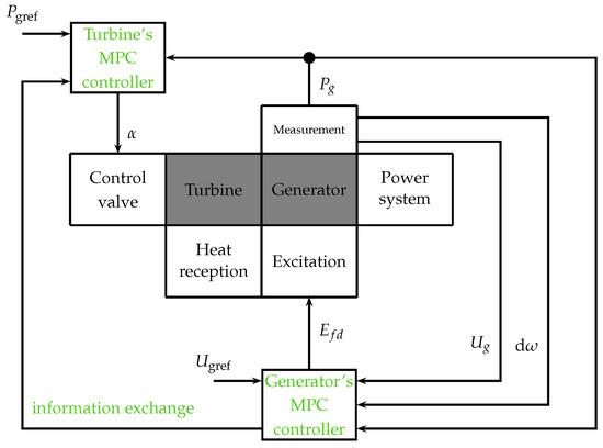
Figure 3.
Coordination of turbine and generator MPC controllers (proposed changes to the structure marked in green).
In this structure, many different types of information can be exchanged between the controllers. In the proposed system, only the values of the and control signals are exchanged between the controllers. The proposed solution in form of two QDMC controllers with the exchange of information about the current control signals ( and ) is shown in more detail in Figure 4.
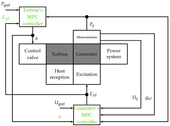
Figure 4.
Proposed distributed MPC control system structure with local QDMC controllers exchanging control signals (proposed changes to the structure marked in green).
The proposed solution uses MPC controllers that use the knowledge of the plant models to calculate the control signals. The models, on the basis of which each of the controllers works, take into account the influence of the control signal coming from the second control system. As a result, the obtained step response used in each of the controllers in the QDMC algorithm contains information about the influence of other controllers on the plant. The exchange of information between QDMC controllers on an ongoing basis and updating the parameters of the online model allows us to react to changes taking place in the plant. Optimization tasks are solved in parallel, which can significantly affect the speed of calculations (in relation to centralized solutions), which is of great importance in systems where time is important (fast-changing processes, i.e. electrical and electromagnetic phenomena).
In the case of a turbine set, the proposed control system can be presented in the form of Equations (4)–(7):
where:
—turbine controller function (QDMC controller);
—generator controller function (QDMC controller);
—online turbine parameter identification function (RLS);
—online generator parameter identification function (RLS);
—parameters of the turbine set model used by the turbine controller;
—parameters of the turbine set model used by the generator controller.
Figure 5 shows a diagram of the proposed system as described above. Two RLS blocks are responsible for identifying the models for both controllers based on information coming from both the plan and the controllers. The control systems use the calculated models to calculate control signals and . Figure 6 shows the various stages of the algorithm’s work in time: online RLS identification, calculation of control signals, and processes taking place in the turbine and generator. In every step the model is updated and the new control signal is calculated. In the same instant k the turbine interacts with the generator and there is information exchanged between the two controllers. The whole sequence repeats itself for every step of the algorithm.
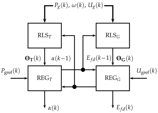
Figure 5.
The proposed control loop of the turbine generator set.
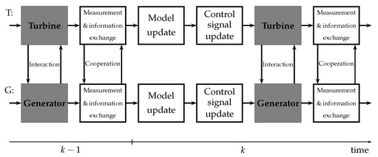
Figure 6.
Stages of the algorithm executed in time for turbine and generator loops.
The control signals and at time k are calculated on the basis of the values of the controlled quantities, setpoints, the control signal of the second controller at the time and the parameter vectors of and . The parameters of the models at the time k are calculated in each step of the algorithm on the basis of the inputs and outputs of the object and the parameters at the time .
Along with the development of complex model-based control algorithms and communication networks, cooperating distributed predictive control can also form the basis for systems with more components, allowing for the expansion of the proposed solution with new elements in the future (e.g., a transformer or reactor controller). Such development of the solution in the future is fully consistent with the object-oriented, modular approach used and allows for the full use of the developed cooperation base.
4. Analysis of Simulation Results
Simulation tests in the Matlab/Simulink environment included the analysis of various variants of information exchange between the two control systems: the turbine controller and the generator controller. It was assumed that the information exchanged would be a control signal generated by a given controller, which is to help the controller’s partner in determining the influence of the operation of the other controller on its own operation. In order to better visualize the influence of information exchange on control quality, it was decided to use ISE/ITSE [4] integral quality indicators (in [29] the authors consider different control performance indices), which enable direct comparison of the operation of various systems. It was decided to distinguish between four different test cases to get the full picture of the cooperation efficiency: no information exchange, one-way exchange (transmission of information about a change in the opening angle of the control valve or information about the change in excitation voltage ), and two-way information exchange ( and ).
Additionally, two different controllers were used. Controller 1 uses parameters that give the smallest oscillations (from the feasible range of the parameters) and Controller 2 uses parameters selected during an optimization process [4]—the minimization of ISE/ITSE integrals indices to reduce the error of active power , generator voltage , and angular velocity w. The prediction and control horizons (controller parameters) were selected as follows [4]: set 1: , ; set 2: , .
The obtained results of the simulation test studies are presented in Figure 7 and Figure 8. Both figures consist of five subplots presenting different signals important in the analysis. The first three present controlled values (following the set power trajectory) and the generator voltage’s amplitude () and frequency (), which both should be stabilized at 1 p.u. The fourth and the fifth subplot present the control signals responsible for the turbine’s () and generator’s () control.
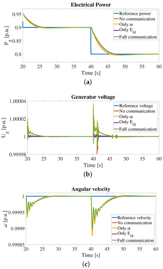
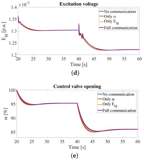
Figure 7.
Results for controllers with parameter set 1.
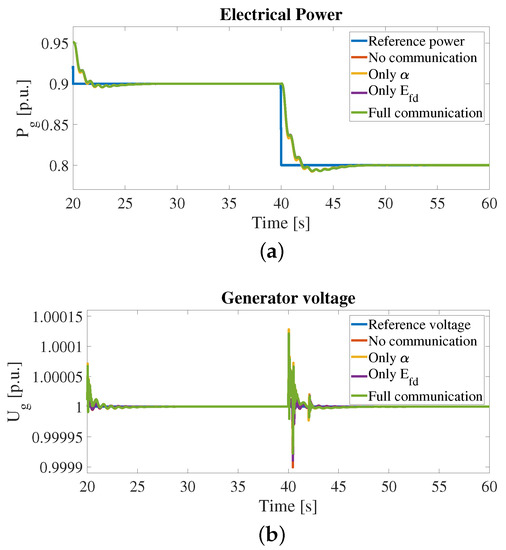
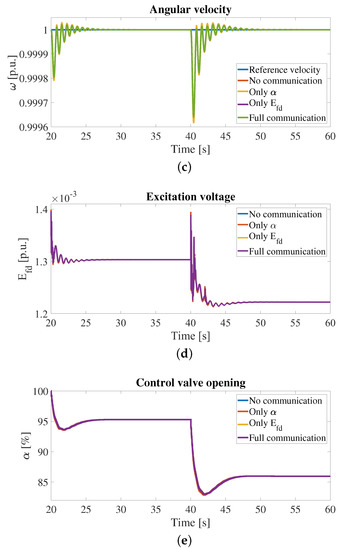
Figure 8.
Results for controllers with parameter set 2.
The models of a turbine and of a generator coupled with their control loops are highly complex systems. As a result, after the initialization phase at the beginning of each simulation, some transient behavior is observed, which decays within the first 20 s of each simulation. The source data for the analysis is therefore selected as the measurement series from the 20th second and on to ensure the initialization phase is over, and all transients are not present.
Figure 9 and Figure 10 (parameter sets 1 and 2 accordingly) contain three subplots each, which show the error of (a) following the set power trajectory, (b) stabilization of voltage, and (c) stabilization of angular speed (voltage frequency). Those figures show in detail the error signals that were used for the calculation of ISE/ITSE indices (integral of those signals and integral multiplied by time respectively). Values of the obtained ISE/ITSE indices are presented in Table 1.
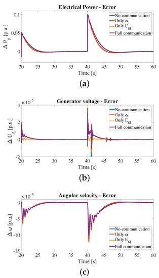
Figure 9.
Errors for controllers with parameter set 1.
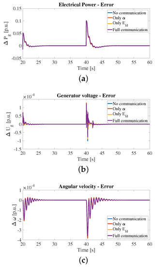
Figure 10.
Errors for controllers with parameter set 2.

Table 1.
ISE and ITSE indices for controllers with par. set (a) 1 and (b) 2.
4.1. ISE-Based Analysis
The first part of the analysis of the result was the comparison of the received ISE index values. All ISE values were compared to values of the index for the case with no cooperation. It was made to see how each of the cases improves or worsens the quality of control for every single controlled value. The index has its best value for the controller exchanging only the signal 1.49% (set 1) and 0.33% (set 2) better than for the system without any communication. For two consecutive cases the change in quality (in comparison to the system without any cooperation) is −15.42% (only , set 1), −4.01% (only , set 2), −13.17% (full cooperation, set 1), and −3.51% (full cooperation, set 2). For the controllers exchanging only signal index is 67.74% (set 1) and 21.76% (set 2) better than for the system without any cooperation. At the same time, for the same controller (only ) is 22.51% (set 1) and 13.45% better in comparison with the control system without any cooperation. For this controller, both indices have the best values. On the other hand values of for the other cases are are as follows: −92.30% (only , set 1), −76.12% (only , set 2), −90.16% (only no cooperation, set 1), and −73.37% (no cooperation, set 2) different in comparison to the system without any cooperation. For values for the other cases are are as follows: −1.56% (only , set 1), 0.29% (only , set 2), 18.99% (only no cooperation, set 1), and 13.22% (no cooperation, set 2) different in comparison to the system without any cooperation.
4.2. ITSE-Based Analysis
The second part of the analysis consisted of the ITSE index comparison. The results were similar to those for ISE in reference to the cases where the index had its maxima and minima. The index has its best value for the controller exchanging only the signal 1.57% (set 1) and 0.35% (set 2) better than for the system without any communication. For two consecutive cases the change in quality (in comparison to the system without any cooperation) is −16.33% (only , set 1), −4.17% (only , set 2), −13.96% (full cooperation, set 1), and −3.66% (full cooperation, set 2). For the controllers exchanging only signal index is 69.32% (set 1) and 22.53% (set 2) better than for the system without any cooperation. At the same time, for the same controller (only ) is 22.37% (set 1) and 13.34% better in comparison with the control system without any cooperation. For this controller, both indices have the best values. On the other hand values of for the other cases are are as follows: −90.84% (only , set 1), −71.07% (only , set 2), −88.34% (only no cooperation, set 1), and −67.58%(no cooperation, set 2) different in comparison to the system without any cooperation. For values for the other cases are are as follows: −1.44% (only , set 1), 0.30% (only , set 2), 17.17% (only no cooperation, set 1), and 13.03% (no cooperation, set 2) different in comparison to the system without any cooperation.
4.3. Result Discussion
The obtained results show that the application of information exchange, contrary to expectations, does not globally improve the quality of control in all cases. The turbine and generator interact with each other as they are based on a common shaft. Due to this fact improvement of control quality for one of the controllers (turbine or generator) influences the operation of the second controller (similar issues discovered and described in [1,2,3,4]). It means that, while the addition of an additional communication channel transmitting information about the change of the excitation control signal significantly improves the voltage stabilization, the exchange of information about the degree of valve opening improves tracking of the active power set trajectory. Improvement in one way means a decrease in the second controller’s control quality. This means that, although according to the assumptions adding additional information may have a positive effect on the control system, in some cases the effect may be opposite to the expected one and each case should be analyzed individually.
The use of full information exchange combines the advantages and disadvantages of two solutions with a one-way exchange. Although the sum of ISE/ITSE indices for all parameters (, , w) for the fully cooperating system is not the best, for every separate index the value is in the middle between the best and the worse one-way communication system. As the fully cooperative system does not excel in any single index, it combines the pros and cons of the other considered cases.
Since, as mentioned earlier, one of the features of cooperative objects is voluntary, in this case, the information exchange can only be used in one direction in order to obtain the highest value of one of the indexes. Additionally, the comparison of the two parameter sets shows that the leading communication strategies are the same regardless of the controller parameters. Although the overall quality (in sense of ISE/ITSE) criteria is different for both considered cases, for individual ISE/ITSE the minima are still in the same places for the same ways of communication. It proves that the observed dependence is totally independent of the controllers’ parameters and has an additional effect and influence on the performance of the control system.
5. Conclusions
The paper describes a cooperative predictive MPC control system for a nuclear power plant turbine generator set. The authors discuss the definition and importance of cooperation in controlling a system of many controllers. It was proposed to use QDMC control systems that exchange information about the control signal, which a partner controller can use in order to better predict the behavior of the turbine generator set in the future. The paper considers different variants of information exchange: lack of communication, one-way information exchange, and two-way information exchange between controllers. The results of the simulation tests show that the application of the control signal information exchange allows for an increase in the control quality, but not always the information exchange benefits the system. In the case with full cooperation, the result combines the advantages and disadvantages of the other solutions with ISE/ITSE indices with values in the range between a minimal and maximal value of considered indices.
The developed and presented method of cooperation between MPC controllers in a nuclear power plant, thanks to its modularity, is the basis for an extensive, multi-agent control system consisting of a larger number of controllers (e.g., adding a transformer’s or reactor’s controllers).
The discussed solutions were used in the research of the distributed control system of the turbine generator set in [1,2,4]. Further research should focus on further optimization of control of the turbine set in a nuclear power plant using self- and event-triggered control to reduce the amount of needed energy.
Author Contributions
Conceptualization, P.S., B.C. and D.H.; methodology, P.S.; software, P.S.; validation, P.S., B.C., T.A.R., D.Z. and D.H.; formal analysis, D.H. and P.S.; investigation, B.C. and P.S.; resources, P.S. and B.C.; writing—original draft preparation, P.S., B.C. and D.H.; writing—review and editing, B.C., D.H., T.A.R. and D.Z.; visualization, P.S.; supervision, D.H. and B.C.; funding acquisition, D.H. All authors have read and agreed to the published version of the manuscript.
Funding
This research was funded in part by the Poznan University of Technology under Grant 0214/SBAD/0237.
Data Availability Statement
The data presented in this study are available on request from the corresponding author.
Conflicts of Interest
The authors declare no conflict of interest.
Nomenclature
| PS | Power System |
| PSS | Power System Stabilizer |
| MPC | Model Predictive Control |
| DMC | Dynamic Matrix Control—A version of an MPC algorithm |
| RLS | Recursive Least Squares |
| DMPC | Distributed MPC |
| QDMC | Quadratic Dynamic Matrix Control |
| QP | Quadratic Programming |
| ISE | Integral of Squared Error |
| ITSE | Integral of Time-weighted Squared Error |
| Active power | |
| Generator’s RMS voltage | |
| Generator QDMC controller’s prediction horizon | |
| Turbine QDMC controller’s prediction horizon | |
| THD | Total Harmonic Distortion |
| Active power | |
| Reactive power | |
| Generator’s current | |
| Generator’s angular speed | |
| Excitation voltage | |
| Power system’s voltage | |
| Power system’s voltage frequency | |
| p | Steam pressure |
| Control valve opening | |
| Steam vent valve opening for the heat generation | |
| Mass flow of the steam for the heat generation | |
| Control valve opening |
References
- Sokólski, P.; Rutkowski, T.; Duzinkiewicz, K. The distributed model predictive controller for the nuclear power plant turbo-generator set. In Proceedings of the 22nd International Conference on Methods and Models in Automation and Robotics, Miedzyzdroje, Poland, 28–31 August 2017. [Google Scholar]
- Sokólski, P.; Rutkowski, T.A.; Ceran, B.; Horla, D. Robustness Analysis of a Distributed MPC Control System of a Turbo-Generator Set of a Nuclear Plant—Disturbance Issues. In Automation 2021: Recent Achievements in Automation, Robotics and Measurement Techniques; Springer: Cham, Switzerland, 2021. [Google Scholar]
- Sokólski, P.; Rutkowski, T.A.; Ceran, B.; Horla, D.; Złotecka, D. Power System Stabilizer as a Part of a Generator MPC Adaptive Predictive Control System. Energies 2021, 14, 6631. [Google Scholar] [CrossRef]
- Sokólski, P.; Rutkowski, T.; Ceran, B.; Horla, D.; Złotecka, D. Numbers, Please: Power—and Voltage-Related Indices in Control of a Turbine-Generator Set. Energies 2022, 15, 2453. [Google Scholar] [CrossRef]
- Grote, W. Ein Beitrag zur Modell Basierten Regelung von Entnahmedampturbinen. Doctoral Thesis, Ruhr-Universität Bochum, Bochum, Germany, 2009. [Google Scholar]
- Kulkowski, K.; Kobylarz, A.; Grochowski, M.; Duzinkiewicz, K. Dynamic model of nuclear power plant steam turbine. Arch. Control Sci. 2015, 25, 65–86. [Google Scholar] [CrossRef]
- Perycz, S.; Prochnicki, W. The Mathematical Model of a Nuclear Power Plant VVER Block Steam Turbine Allowing to Study Transient Processes with w=var; Technical Report; Faculty of Electrical and Control Engineering, Gdansk University of Technology: Gdansk, Poland, 1989. [Google Scholar]
- Imielinski, A. Mathematical Model of Synchronous Generator for Full-Scope Simulator; Technical Report; Faculty of Electrical and Control Engineering, Gdansk University of Technology: Gdansk, Poland, 1987. [Google Scholar]
- Karnouskos, S.; Marrón, P.J.; Minder, D. The Emerging Domain of Cooperating Objects; Springer: Berlin/Heidelberg, Germany, 2012. [Google Scholar]
- Lewis, F.L.; Zhang, H.; Hengster-Movric, K.; Das, A. Cooperative Control of Multi-Agent Systems: Optimal and Adaptive Design Approaches; Springer: Berlin/Heidelberg, Germany, 2014. [Google Scholar]
- Shamma, J. Cooperative Control of Distributed Multi-Agent Systems; Wiley: Hoboken, NJ, USA, 2007. [Google Scholar]
- Maestre, J.M.; Negenborn, R.R. Distributed Model Predictive Control Made Easy; Intelligent Systems, Control and Automation: Science and Engineering; Springer: Dordrecht, The Netherlands, 2014. [Google Scholar]
- Rawlings, J.B.; Mayne, D.Q.; Diehl, M. Model Predictive Control: Theory, Computation, and Design; Nob Hill Publishing: Madison, WI, USA, 2017. [Google Scholar]
- Zhao, W.; Zhang, B.; Chai, S.; Cui, L.; Yao, F. Distributed model predictive control of linear systems with unmeasurable states and uncertain parameters. In Proceedings of the 2017 32nd Youth Academic Annual Conference of Chinese Association of Automation (YAC), Hefei, China, 19–21 May 2017; pp. 916–921. [Google Scholar] [CrossRef]
- Giselsson, P.; Rantzer, A. On Feasibility, Stability and Performance in Distributed Model Predictive Control. IEEE Trans. Autom. Control 2014, 59, 1031–1036. [Google Scholar] [CrossRef]
- Giselsson, P.; Rantzer, A. Distributed Model Predictive Control with Suboptimality and Stability Guarantees. In Proceedings of the 49th IEEE Conference on Decision and Control, Atlanta, GA, USA, 15–17 December 2010; Volume 59. [Google Scholar]
- Chopard, B. An Introduction to Metaheuristics for Optimization; Springer: Cham, Switzerland, 2018. [Google Scholar]
- Reynolds, C.W. Flocks, Herds, and Schools: A Distributed Behavioral Model. In Proceedings of the 14th Annual Conference on Computer Graphics and Interactive Techniques, Anaheim, CA, USA, 27–31 July 1987; pp. 25–34. [Google Scholar]
- Dragoi, E.N.; Dafinescu, V. Review of Metaheuristics Inspired from the Animal Kingdom. Mathematics 2021, 9, 2335. [Google Scholar] [CrossRef]
- Spudić, V.; Conte, C.; Baotić, M.; Morari, M. Cooperative distributed model predictive control for wind farms. Optim. Control Appl. Methods 2015, 36, 333–352. [Google Scholar] [CrossRef]
- Carli, R.; Cavone, G.; Pippia, T.; De Schutter, B.; Dotoli, W. A Robust MPC Energy Scheduling Strategy for Multi-Carrier Microgrids. In Proceedings of the 16th IEEE International Conference on Automation Science and Engineering (CASE), Virtual, 20–21 August 2020. [Google Scholar]
- Del Real, A.J.; Arce, A.; Bordons, C. An Integrated Framework for Distributed Model Predictive Control of Large-Scale Power Networks. IEEE Trans. Ind. Inf. 2014, 10, 197–209. [Google Scholar] [CrossRef]
- Ławryńczuk, M.; Marusak, P.M.; Chaber, P.; Seredyński, D. Initialisation of Optimisation Solvers for Nonlinear Model Predictive Control: Classical vs. Hybrid Methods. Energies 2022, 15, 2483. [Google Scholar] [CrossRef]
- Maciejowski, J.M. Predictive Control: With Constraints; Pearson Education: New York, NY, USA, 2002. [Google Scholar]
- Duzinkiewicz, K.; Kobylarz, A.; Kulkowski, K.; Grochowski, M.; Rutkowski, T.A.; Sokólski, P. Wielobszarowy system sterowania turbozespołu elektrowni jądrowej. Zesz. Nauk. Wydziau Elektrotechniki Autom. Politech. Gdaskiej 2015, 42. [Google Scholar]
- Sokólski, P.; Kobylarz, A.; Kulkowski, K.; Duzinkiewicz, K.; Rutkowski, T.; Grochowski, M. Advanced control structures of turbo generator system of nuclear power plant. Acta Energetica 2015, 3, 83–96. [Google Scholar] [CrossRef][Green Version]
- Sokolski, P.; Rutkowski, T.; Duzinkiewicz, K. The excitation controller with gain scheduling mechanism for synchronous generator control. In Proceedings of the 2015 20th International Conference on Methods and Models in Automation and Robotics (MMAR), Miedzyzdroje, Poland, 24–27 August 2015; pp. 23–28. [Google Scholar]
- Duzinkiewicz, K. Zintegrowane Sterowanie Systemami Zaopatrzenia w Wodę Pitną; Uczelniane Wydawnictwo Naukowo-Dydaktyczne AGH: Krakow, Poland, 2005. [Google Scholar]
- Domański, P.D.; Ławryńczuk, M. Impact of MPC Embedded Performance Index on Control Quality. IEEE Access 2021, 9, 24787–24795. [Google Scholar] [CrossRef]


Publisher’s Note: MDPI stays neutral with regard to jurisdictional claims in published maps and institutional affiliations. |
© 2022 by the authors. Licensee MDPI, Basel, Switzerland. This article is an open access article distributed under the terms and conditions of the Creative Commons Attribution (CC BY) license (https://creativecommons.org/licenses/by/4.0/).