
Overview of Hybrid Excitation in Electrical Machines

Division of Electricity, Department of Electrical Engineering, Uppsala University, 752 36 Uppsala, Sweden
*
Author to whom correspondence should be addressed.
Energies 2022, 15(19), 7254; https://doi.org/10.3390/en15197254
Submission received: 24 August 2022
/
Revised: 16 September 2022
/
Accepted: 23 September 2022
/
Published: 2 October 2022
Abstract
:Hybrid excitation is a technology that combines the advantages of field windings and permanent magnets for inducing magnetic flux. This article studies the benefits of hybrid excitation and provides an outlook on their possible applications, such as wind power generators and electric vehicle motors. Compared to permanent magnet-based machines, hybrid excitation gives a variable flux while still using the advantage of the permanent magnets for a portion of the flux. This article also looks into some different categories of machines developed for hybrid excitation. The categories are based on the reluctance circuit, the relative geometrical location of the field windings relative to the permanent magnets, or the placement of the excitation system.
1. Introduction
Hybrid excitation (HE) synchronous machines uses both electromagnets and permanent magnets (PM) to establish the magnetic fields in generators, that is, a combination of permanent magnet synchronous machines (PMSM) and wound-rotor synchronous machines (WRSM). It combines the advantages of each technology so that the permanent magnets can reduce the field windings (FW) and decrease the field current, but the field current can still create a variable magnetic flux.
PMSM usually have the benefit of being able to reduce the volume and weight of the magneto-motoric force while also avoiding the copper losses of the field current. Moreover, they have the disadvantage of a non-variable magnetization so the magnetic flux cannot be controlled (as it can be controlled in WRSM). In this way, it could be desirable to introduce a variable flux, which would enable the control of the voltage, reactive power, power, or torque depending on the system of the application.
There have been several review papers written about hybrid excitation. Many present the wide variation of designs focused on the classification of the machines [1,2,3,4,5,6,7,8], whereas other studies focus on specific topics such as machine modeling [9] or the application to electric vehicles (EV) [2,10,11,12,13,14]. There have also been papers that presented overviews of more specific categories, such as the review about hybrid excitation for DC machines [15], whereas others presented broader perspectives, such as the reviews of variable flux PM machines [3,16,17,18], which also covered other methods to obtain a variable flux. However, many other papers in addition to review papers have provided a general description of the subject [19,20,21,22]. There has been a steadily increasing number of publications on the topic since the first papers about hybrid excitation machines were published in the late 80s and early 90s [10]. However, some early combinations of PMs and field windings were designed as far back as the 50s [23].
The name “hybrid excitation” is the most commonly used term in the literature to describe these machines, but they are also referred to by many other names throughout the literature, such as double-excitation synchronous machines, dual-excitation synchronous machines, or combined-excitation synchronous machines [9,10,14]. Other names that more specifically describe the methods for combining one additional source with a main source are also used. These are “Permanent magnet synchronous machines with auxiliary exciting windings” [24,25], or wound-rotor synchronous machines with “assisting permanent magnets” [26,27,28].
Overview of This Article
This article is organized as follows:
Section 2 briefly describes the magnetic flux and the induction of the voltage. Section 3 describes the advantages of HESM based on comparisons of PMSM and WRSM. Section 4 provides an outlook of possible applications. Section 5 describes different ways of categorizing hybrid excitation; these categories form the basis for the subsequent sections. Section 6 is based on the reluctance circuit. Section 7 is based on different ways of combining FW poles and PM poles. Section 8 discusses the excitation system. Section 9 describes some other specific hybrid excitation concepts and Section 10 briefly describes some other technologies with similarities to Hybrid excitation.
2. The Excitation Flux
An electrical machine works by Maxwell–Faradays law (), where a voltage is induced in an armature coil by an alternating magnetic flux through that coil, as in
that is, an EMF, E induced by the change in the flux , as in
As a first simple approach, the combined flux could be written as
However, the total flux path of the magnetic circuit and the reluctance of the iron depends on the flux density, where the flux from the field winding is controllable as in since it is possible to control the flux in the machine by controlling the magnetic field current . Field windings (FW) establish the magnetic field through electric coil windings. In this way, the electric excitation is based on electromagnets consisting of exciting windings that establish a wound field.
The basic idea of hybrid excitation is to combine this advantage of electromagnets with the advantages of permanent magnets. Except for a controllable flux, there are also other advantages of hybrid excitation including the increased variety of designs that could be created when optimizing the hybridization.
Several studies have expressed the ratio of the flux from the FW to the flux from the PM, for example, the study of the influence of the “ratio of hybridization” by Ammar et al. [10,29,30,31,32].
This ratio could act as a way of analyzing the operation and how the field winding flux is operated compared to the PM flux, as well as for studying the flux density distribution and the output performance for different field currents .
The ratio could also be used as a tool for optimizing the design, for example, to see how the PM part should be dimensioned compared to the FW part [30,33,34]. This provides design freedom in terms of how the benefits of PM excitation are combined with electrical excitation, making it is possible to optimize the design regarding the material costs, operational costs, spatial volume, machine weight, and performance.
Rather than seeing hybrid excitation as a combination, there is also an alternative approach that considers one as a support of the other, where either the PM or the FW is considered the main source of excitation and the other excitation only acts as an additional support. One such approach considers the field winding as the main source with the assistance of permanent magnets [26,27,28,35,36], whereas the opposite strategy considers the PM as the main source with additional support from the FW [24,25].
The design of the machine must be dimensioned for an interval flux
The variable flux is then designed to allow all feasible levels of flux through the air gap. The effective area of the pole pitch (approximately the width of the pole body iron) has to be dimensioned for both the FW flux and the PM flux.
3. Benefits of Hybrid Excitation
The main advantage of electric excitation by field windings is the control of the variable flux density. By introducing hybrid excitation, the field current can be reduced by the addition of permanent magnets, which decreases losses and the related cooling.
There are also other benefits of permanent magnets that could be used when optimizing hybrid excitation designs. Permanent magnets can improve the small size of the machine. This is especially important when the size and weight are important, for example, in electric vehicles and wind power.
Field windings in addition to PMs can also handle the risks of the demagnetization of permanent magnets as they can strengthen the excitation flux to counteract high fields from the risk of high-armature currents.
In general, hybrid excitation can provide a higher degree of freedom in the design of a machine, which can optimize the costs of the machine, either by reducing the amount of materials and components used in the construction of the design or by increasing the efficiency and reliability.
3.1. Advantage of Variable Flux in Hybrid Excitation
The main advantage of hybrid excitation machines is usually that the flux is variable. This is in contrast to PMSM, where the flux density cannot be controlled. The variable flux level can change the voltage level of the induced EMF, making it controllable.
In motor applications, this can be used to improve the performance of machines that are operated at a wide range of speeds. The benefits are related to field weakening [37,38], where the power and torque can be controlled depending on the operation speed. Such benefits have been studied by Cinti et al. [34], who compared PM machines and HE machines, and showed the advantages of operating with a good efficiency at variable speeds. Such strategies for flux weakening in hybrid excitation have been studied by Giulii-Capponi et al. [39,40], Amara et al. [29], ShahMohammadi et al. [32], and Michieletto et al. [41].
An inverter-fed PMSM (Figure 1) is used to control the field-weakening strategies (illustrated in Figure 2). At low speeds under the base speed (), the torque is kept at a constant maximum and the power is linear to the torque depending on the speed.
At high speeds above the base speed (), the current is controlled to obtain the field-weakening. The flux is reduced and controlled by changing the angle of the current while maintaining the maximum current limit (see Figure 2). If the stator current is seen as two components (), the flux is weakened by an increased negative component in the flux direction (). Within the field-weakening region, the power is controlled to obtain a constant power . The torque decreases proportional to the inverse of the speed
At high speeds, there is still an upper speed limited by a maximum speed, which is set by the voltage and current constraints, that is, the constant power speed range (CPSR), written as
Hybrid excitation can be used to improve the torque–speed relation of relative conventional PMSM [32] (illustrated in Figure 3). At low speeds, the torque can be increased by a higher back EMF, E, considering that the torque is given by
The increased back EMF is obtained by a higher field current () (see Figure 3a), so that the torque is
At high speeds, it can instead improve the maximum speed [32], which then is obtained by a lower field current () (see Figure 3b), that is
The efficiency of a motor is related to the speed and torque and is often expressed by an efficiency map [42,43,44], which describes the efficiency () as a function of the torque and speed (). Although comparing them makes it clear that PMSM have a high general efficiency due to lower rotor power losses, WRSM gain advantages due to the variable flux [45]. PMSM have some regions with high efficiency, whereas WRSM can optimize the operation of the FW current to improve the area of high efficiency [12]. This can be seen in the comparison in Figure 4.
The field currents can create variations in the efficiency map, where both the torque–speed curve is changed and the region of high efficiency is moved [46]. This can be seen in Figure 5. As a result, the variable torque–speed curve shares some similarities with the impact of the gear boxes, where the torque–speed relation changes.
The benefits are slightly different depending on the type of network and the grid connection. This could either be an indirect connection through an inverter or an synchronous grid connection directly to the grid (see Figure 6). The benefits in the case of an inverter connection are linked to the advantages of flux weakening, whereas the benefits of a direct connection are linked to the control of the voltage or the reactive power.
In generator applications, a variable excitation flux is useful for controlling the voltage level or for compensating reactive power loads. The benefits of producing and consuming reactive power have been mentioned by several authors [30,47]. The benefits of local power generation have been addressed by Kamiev et al. [25] for marine ships and by Sun et al. [48] for generators in aircrafts.
The rotor flux is variable through the field current (as seen in Figure 7a), and the magnitude of the alternating stator flux controls the induced back EMF of the stator windings (as seen in Figure 7b). The control of the EMF can be used to control the load angle between E and since the stator output voltage is
The load angle is also dependent on the phase angle , which relates to the reactive power. With the unity power factor (as seen in Figure 7c), the voltage and current is in the phase. An over-excited generator with a high EMF can deliver reactive power to inductive loads (as seen in Figure 7d), whereas an under-excited generator can consume reactive power from capacitive loads (in Figure 7e).
When a generator is operating in a small local grid (in “island operation”), the excitation flux can be used to control the voltage level so that a high flux gives a high voltage and vice versa. When a generator is connected to an actual power grid, the voltage level is instead set by the complete contributions of the grid by the control of the transmission system operator (TSO). The variable flux instead acts as a compensator for reactive power so that a high flux (over-excitation) delivers reactive power and a low flux (under-excitation) consumes reactive power.
3.2. Optimization of Volume and Weight in Hybrid Excitation Designs
Permanent magnet machines can often be designed with a smaller size and weight compared to wound field machines. Hybrid excitation can in this way be used to decrease a machine’s volume and mass while still having a variable flux [30].
Wound poles usually contribute to the volume and weight since they consist of both the copper field windings and iron lamination core. The field windings not only introduce the insulation material and sufficient cooling system but also the excitation system that supplies the DC field current.
Permanent magnets, on the other hand, can help to reduce the volume and weight by decreasing the size of the rotor poles. Small-sized rotor poles enable either a decreased rotor radius or a decreased rotor mass. As a consequence, it may also be possible to also decrease the stator size, which further optimizes the weight and size [33]. Other benefits of small poles include the decreased saliency (increased non-saliency) due to the effective usage of the pole pitch [49].
The width of the flux path of the yoke () has to be dimensioned to match the width of the pole body () as approximately half the width of the total width of the pole flux (). This can be seen in Figure 8. The field windings take up space within the rotor (Figure 8b), which affects the width of the iron of the pole body and the volume of the rotor yoke. This can affect the inner radius () since it has to be much smaller than the rotor air gap radius (). A PM-based rotor constructed with RE magnets takes up less space than a wound rotor, as seen in Figure 8c. However, it is worth considering that the saturation of the stator slots creates a limit in the amount of flux per pole pitch, which also affects the design of the rotor. However, the decreased size of the rotor pole can still be used to decrease the size or volume of the rotor or the total machine.
Some of the advantages of hybrid excitation are that the size and mass of the rotor poles can be kept low compared to overall designs that only use field windings, as the field windings and their cooling can be decreased. This keeps the overall size and mass of the machine low, which is important in conventional wind power applications where the generator is mounted in a generator tower [33].
Electric excitation gives an MMF using the wound field current as
whereas a permanent magnet gives an MMF based on the remnant magnetization for the magnet length
This can be seen as an equivalent current of the sides of the permanent magnet.
The equivalent current of the permanent magnets contributes to the MMF without any additional space and without resistive losses.
The density of permanent magnets is comparable to those of steel and iron, as seen in Table 1. This shows that permanent magnets do not introduce any additional weight due to their small volume. Conductors in field windings are instead introducing both volume and weight compared to permanent magnets.
It should be noted that the comparisons of sizes are highly dependent on which PM material is studied. Rare earth magnets (such as SmCo or NdFeB) can establish a high flux density for their size. This is not the case for other magnets such as ferrite, which may still need a large volume to establish a high flux density. The size deponent benefits of hybrid excitation are clearly based on the designs of rare earth magnets.
Similar benefits can be found in motor applications, where weight and volume are important design constraints such as in electric vehicle applications. Pure FW designs have been compared to pure PM designs in hybrid electric vehicles. The performance has to be set in contrast to the volume or the mass of the design, such as comparing torque per volume (T/V [Nm/m3]) or torque per mass (T/m [Nm/kg]). Field-winding excitation can be a low-cost alternative to PM excitation and operates at a wide constant power range [50]; however, PM excitation could be designed with an improved torque density (both considering T/V and T/m) [45]. Hybrid excitation could then be a way of combining these advantages of the two technologies.
3.3. Decrease Risks with Hybrid Excitation
Field windings in the excitation system can compensate for some of the risks of the demagnetization of the permanent magnets. They are then used to handle fault tolerance issues by reducing risks, decreasing faults, and decreasing the need for maintenance [25]. The auxiliary winding from the electric excitation can be used to compensate for the fields from the reactions in the armature-winding current [24].
It should also be noted that the risk of PM demagnetization is increased at higher temperatures for most permanent magnets [51], which is relevant when placing PMs combined with currents since they may become heated. These risks are highly dependent on the material, for example, heating clearly could reduce the remanent flux density () and the coercivity () of neodymium magnets (due to the low Curie temperature of NdFeB) but this is not as clear for SmCo magnets (with a higher Curie temperature). A hybrid excitation needs to place the magnets in a way that voids the heating from the field current. However, ferrite instead has an increased coercivity () at increased temperatures and could have an advantage in this context. Some demagnetization-related parameters can be seen in Table 2 [52,53].
Another approach is to focus on the risks of the field windings, rather than the risks of the permanent magnets. The field windings are dependent on the DC supply of the excitation system, which can decrease its availability and needs maintenance. The risks of maintenance of the excitation system for the DC field current can cause higher downtimes for FW generators [33]. A generator built with PM excitation can still establish a magnetic flux when there is a loss of the field windings [33]. PM excitation could then compensate for some risks with FW excitation.
3.4. Optimization of Economic Aspects in Hybrid Excitation
Hybrid excitation provides more alternatives when optimizing a machine design, which can be used to improve the costs of the design. An economical model for generators includes the following cash flow analysis [33]:
- Investment costs (considering the machine itself and its construction in an application),
- Net production income (considering efficiency and availability),
- Operational and maintenance costs,
- Replacement costs (at end of operational life),
In this case, based on the calculations for wind power generation by McDonald [33], the benefits can be seen in the investment costs and also the operational and maintenance costs.
The investment costs are first linked to the cost of the permanent magnet material, where RE magnets (NdFeB and SmCo) have a high price and availability issues [54]. So, although RE magnets help to decrease the size of a design, they also introduce high material costs [30]. The price of RE PMs are usually much more expensive than the copper used in wound field excitation [50], and there could be complications with the assembling of the PMs in a design [45]. In this way, it is possible to see FW as a low-cost alternative to RE PMs, which could instead cause additional costs due to their effect on size and weight. Wound field excitation takes up volume due to the iron, coil, insulation, and cooling, which affect the costs of many applications [45]. An increased volume and weight can result in the increased costs of a turbine tower in wind power applications [33], which is also of interest for EV applications. Hybrid exaction could then be an alternative that decrease the costs of the PM while also keeping the costs of the size and weight low [33].
Rotor power losses, are mostly related to the field current and the field windings, since the iron losses are negligible in a rotor (the magnetic flux is not alternating within the rotor iron as in the stator iron). These rotor losses consist of the resistive losses of the field windings (), but also the losses of the excitation system (), and the cooling of the field windings (), that is,
The field windings have losses due to the field current, as
where the resistance is written as the resistance per turn N
with the circumferential length and the conductor area .
The material conductivity and area can be designed to optimize the impact of the rotor losses while also considering the machine size and weight. The resistivity and density can be seen in Table 3.
Permanent magnets are instead the low-cost alternative when focusing on operational costs [45]. The DC field current introduces copper losses, cooling losses, and the maintenance of the excitation system. Hybrid excitation can then be used as a way of decreasing the operational costs of wound synchronous generators by decreasing the power losses [25]. This increases the efficiency of a generator or a motor, which is not only a question of economics but can also be seen as a question of sustainability, where hybrid excitation plays a role in energy efficiency [12,29].
4. Outlook of Future Applications
Hybrid excitation has been proposed for several applications such as wind power, electric vehicles, and hydro power; examples can be seen in Figure 9. The benefits of the technology differ depending on the application.
4.1. Hybrid Excitation for Wind Power Generators
Present wind power generators exist in various types, such as wound-rotor induction generators (WRIG), doubly fed induction generators (DFIG), and permanent magnet generators (PMSM) with power converters. Hybrid excitation can be seen as an improvement of the type that uses permanent magnet generators due to the introduction of a variable flux or reduction in the amount of PM material.
PMSM in wind power generators are built with power converters, and an HESM could then similarly be introduced together with power converters. The hybrid excitation generator would then use the benefit of the flux control to optimize the back EMF for the converter. Another alternative for the control of the variable flux would be by improving the possibilities of operating the PMSM synchronously with the grid, which then would be directly connected to the network without the converter. Hybrid excitation is preferred compared to other variable flux machines such as wound field synchronous generators since they do not have the same volume and mass. A wind power generator must have a low weight and small size to be able to mount in the turbine tower [33].
The possibility of having a variable flux has been highlighted as an advantage of hybrid excitation for wind power applications [33]. Since wind power is an application with variable speed operation, it is useful to have a variable flux for improving the torque and power for a speed. The flux control of wind power has been studied by Berkoune et al. [55], designed for controlling the voltage in an application for an isolated load.
Some different types of hybrid generators have been proposed for wind power applications. A technology with PM-assisted FW poles (i.e., “parallel flux path”) has been studied by Ployard et al. [35], where a conventional design with both field windings and permanent magnets in the rotor was used. Other designs have avoided the field winding in the rotor. The design by Berkoune et al. [55] had permanent magnets in the rotor and the field windings in the stator. Other designs by Chau et al. [56], Kucuk et al. [57], and Nakamura et al. [58] used a reluctance generator so the excitation system was entirely in the stator. This avoided having the excitation system in the rotor, which only had iron cogs. Another design used two stators and a rotor, for example, the design by Liu et al. [59].
4.2. Hybrid Excitation for Electrical Vehicle Motors
Many motors in electric vehicles are permanent magnet synchronous machines [60,61,62,63]. Hybrid excitation can act as a good alternative that maintains the basic design of PM machines while introducing an additional and variable flux from the field windings.
Flux control is an advantage when considering the variation of loads and the variation of speeds of vehicle traction [29]. Hybrid excitation can be used to improve performance and efficiency at various speeds. This is important considering that vehicles usually operate with different driving patterns. This could help to improve the torque and efficiency at low speeds (which is beneficial for urban driving) while also improving the maximum speed and performance at high speeds (which is beneficial for highway cruising).
The torque can be increased at low speeds for improved acceleration by increasing the flux density. The EMF of the machine can be kept limited at high speeds by decreasing the flux density. There have been studies comparing the comparison IPM and HE, which showed the advantage of the variable flux for variable speed operations [34]. Such strategies for flux weakening in hybrid excitation have been studied by Giulii-Capponi et al. [39,40] and Amara et al. [29] and also in a study that demonstrated that the flux could be deigned based on an approach such as vector control [64].
The high price of rare earth metals has made it desirable to reduce the amount of PM material in vehicle motors. To address this, there are designs that instead combine permanent magnet machines and reluctance machines, which reduces the PM material and decreases costs. These are known as PM-assisted reluctance machines [60,65], which use both ferrite and NdFeB [66,67] and different amounts of PM compared to reluctance machines [68]. Hybrid excitation could act as an alternative way of reducing the amount of PM material by combining PMs with field windings. The torque density of the machine is lower for PM-based excitation compared to field windings, whereas PMs are costlier due to the price of rare earth metals. This is relevant in electric vehicles where it is desired that the motor is kept with a low weight and size at an affordable price [45,50,69].
Different HE motors have been studied for EVs and HEVs by several authors [2,11]. Many different solutions have been proposed and discussed such as parallel flux path machines with PM-assisted field windings by Hwang et al. [70]. In addition, axially separated systems, such as hybridization by an axially segmented rotor for FW and PM by Schofield et al. [71] or the axially segmented stator by Cheng [72], have been proposed. Field windings in the stator for consequent pole and spoke types has been proposed by Kosaka and Matsui [73], Di Barba et al. [74], and Amara et al. [12]. Flux-switching machines with excitation system in the stator [75] have been studied by Hoang et al. [76], Yin et al. [77], Okada et al. [78], and Sulaiman et al. [79]. Furthermore, in-wheel motors have been studied by Hou et al. [80].
4.3. Hybrid Excitation for Hydro Power Generators
The conventional types of generators for hydro power are salient-pole WRSM due to their robustness and variable flux. Hydro power often plays a vital role in the control of a power grid, which makes the control of the flux important. Hybrid excitation is a way of introducing assisting permanent magnets into a WRSM design, which then still is based on field windings.
Hybrid excitation for hydro power has been studied by Kamiev et al. [25] who discussed the advantages of flux control and also how field windings could be used to handle risks with armature reactions.
5. Categorization of Hybrid Excitation Designs
There are numerous designs developed for hybrid excitation. It is then helpful to use categorization as a tool to obtain an easier overview of the extent of HE designs that exist throughout the literature. There are several different ways of categorizing hybrid excitation machines.
Three different approaches can be found in various studies and will be used in this paper. These are based on:
- the reluctance circuit of the magnetic flux path, either PM in series with FW or PM in parallel with FW.
- the location of the excitation system, that is, if the FW and PM are placed in the rotor or in the stator, or if the PMs are in the rotor and the FW are in the stator.
- the geometrical location of the different types of excitation; whether they are different axial segments of the machine or a distribution of different types of poles around the circumference.
The first type of categorization is the most common. It is useful for describing the fundamental obstacle of combining the FW and PM. The FW in series with PMs gives a high reluctance path and the FW in parallel with PMs could give leakage flux. The drawback of the categories is that they may not cover all types of hybrid excitation. Some magnetic circuits are harder to categorize as either parallel or series circuits.
The second categorization gives a broad overview of the excitation system if the PMs and FW are in the stator or in the rotor. It is useful for describing the complexity of the excitation system. If the field current is in the rotor, it may need a more complex excitation system compared to stator-based FW. An excitation current in the stator is then less complex. It is often easy to categorize the machine type, but the number of categories could increase when considering dual-stator or dual-rotor machines.
Other categorizations can vary and can be based on the geometrical location of the FW excitation relative to the PM excitation. Similar categorizations are based on the cylindrical coordinates [4,6] such as axially parallel systems or tangentially parallel systems. This covers other strategies of hybridization that are not directly based on combining the magnetic circuit, for example, machines designed with two different axial segments, which are axially separated but have the same armature windings. Other machines have different types of excitation systems distributed around the rotor circumference and combined through the same armature windings. However, such categorizations may be unclear and many machines may fit into several categories. An overview of the categories can be seen in Figure 10.
6. Basic Flux Path Designs: Series and Parallel
The two most basic ideas underlying hybrid excitation are the series flux path and parallel flux path. These two basics structures of hybrid excitation have been used as a simple method for categorization in several studies [5,6,12,15,17,18,19,40,81,82]. Figure 11 illustrates the reluctance circuit model of each type, together with illustrations of the fundamental method for designing the two types of machines.
Both structures may be simple but they are good for illustrating the two important but basic ideas that need to be considered. Series flux paths have the problem of the high reluctance from the PM, and parallel flux paths could have leakage at low FW field currents.
The magnetization of a material is always has a point of saturation. In soft magnetic materials (i.e., electrical steel), the remanent flux density is low (almost 0) but the permeability is high. This can be seen in Figure 12 on the left. In hard magnetic materials (i.e., permanent magnets), the remanence is usually close to saturation, which results in a low permeability. This can be seen in Figure 12 on the right. A soft magnetic material with a high applied magnetic field strength H also operates at near saturation and similarly has a low permeability (Figure 12 to the left).
For the flux density for electrical steel we have
Above saturation we have
An example of the permeability of iron can be seen in Table 4.
For permanent magnets
The relative permeability is often near (), similar to saturated iron or air. An example of the permeability of PM materials can be seen in Table 5.
A theoretical material, which would have both a high permeability and a high remanence, would be similar to a PM but without using the full potential of the material. It could also be similar to a PM with a parallel iron bridge, which then combines the two materials in parallel. These methods would obtain a medium level remanence and medium level permeability.
Series paths have the disadvantage of the low permeability of PMs (since they could be seen as saturated). Series flux is better for its use of a supporting winding.
Parallel paths have the disadvantage of flux leakage; however, field-winding excitation can use the saturation of iron as an advantage since it decreases the permeability (the slope , incremental permeability) of the leakage.
Both type of designs have their advantages and disadvantages. Some studies have compared specific designs that used serial and parallel flux paths such as Amara et al. [83], Hua et al. [82], and Michieletto et al. [41,84].
6.1. PM in Series with FW
The most basic hybrid excitation design is to place the FW in series with the PM in each machine pole. This used to be called the “series flux path”. A general disadvantage of this design is how the FW flux goes through the PM since PM materials have a high internal reluctance (low permeability). By placing a PM in series with the FW, it becomes like an increased air gap for the overall flux circuit since PMs have a low permeability, which is comparable to air.
When the FW have a low DC field current, the iron of the electromagnet has a low reluctance (high permeability), as seen in Figure 13a. When the FW have a high DC field current, the iron will be saturated and the iron in the electromagnet has a high reluctance (low permeability), as seen in Figure 13b.
6.2. PM in Parallel with FW
The other main design of basic magnetic circuits is to place the PMs in parallel with the FWs. This type of design is often called “PM assisted WRSM”, where the PMs are seen as a support for the FWs [35,36,89].
The flux is in two parallel branches in a “parallel flux path” circuit, and the combined flux of the PM branch and the FW branch induces the excitation flux. Note that the complete system is highly dependent on the FW current since the nonlinear magnetization gives a nonlinear reluctance.
- When the FW have a high DC field current, the iron will be saturated and the iron in the electromagnet has a high reluctance (low permeability). The combined flux from both the FW and the PM then passes through the air gap since the saturated iron has a high reluctance, as illustrated in Figure 14a.
- When the FW have a low DC field current, the iron of the electromagnet has a low reluctance (high permeability) because the PM flux leaks through the iron core when it has a low reluctance. All the flux contributions from the PM may then not pass through the air gap, as illustrated in Figure 14b.
The saturation (of the rotor iron) can be used as an advantage with parallel flux paths since the iron within the FW becomes saturated and then also affects the PM flux. This contributes to increase the PM flux to the stator since the reluctance within the FW increases. The ratio of the flux relative saturation is designed as
where the area can be designed to establish a saturation flux () for a desired field current (assumed to be at max ).
Designs using parallel flux paths have been studied by Yamazaki et al. [26,89,90], Hosoi et al. [91], Ployard et al. [35], Hwang et al. [28], Wardach et al. [36], and Pang et al. [92]. A common solution is to place the PM beside the air gap similar to a PM bridge between the surfaces of two classical FW poles.
6.3. Alternatives to the Basic Flux Path Designs
There are several machine designs that are difficult to categorize, which are based on the magnetic circuit as either series or parallel flux path designs. There are also other approaches where the design aims to avoid some of the limitations of the two structures. Two such alternative flux paths are:
- Overlapping flux paths with an iron bridge, which use series flux paths from both FW and PM fluxes but with an iron flux bridge in parallel besides the PMs.
6.4. Series Flux Path with Iron Flux Bridge
Some designs aim to avoid the high reluctance of the series flux path by designing flux bridges with low reluctivity, as illustrated in Figure 15. The flux bridges are then iron placed as a passage beside a PM or FW. The flux bridge is often placed around a PM or between several PMs. In this way, there is a path for the FW flux with low reluctance (high ) through the iron passages, besides the PM.
An iron bridge is a piece of iron that can introduce a low reluctance in parallel with a high reluctance, where the iron can provide a bridge of low reluctance in addition to a PM, which has a high reluctance.
The solution may not only be seen as a question of the series flux design. Technically, it more resembles parallel flux path designs. If the PM is placed in parallel with an iron flux bridge, it makes the flux bridge act as a passage for leakage flux, similar to other parallel flux designs (see Figure 16), where this leakage flux is established for low field currents (low FW excitation), similar to the typical parallel flux path type. The difference with a proper parallel flux path is that the leakage flux goes through the iron flux bridge rather than through the iron of the FW part. As illustrated in Figure 16.
However, the designs are still based on the structure of a series flux path design and are easier to describe as such, even if they behave similar to parallel flux path designs. In addition, they can be designed to act similar to “series flux path” designs if the flux bridge is designed with a small width. There have been some studies of machines with series flux paths that use flux bridges. One used a structure built by several separated buried PM magnets in one FW pole, as in the design studied by Mudhigollam et al. [49,93]. Another similar design used several PM magnets in one FW pole where internal PM are placed as V-shapes, as in the design studied by Hu et al. [94,95].
6.5. Separated Flux Paths in Parallel
Another way of combining FW and PM excitation is to aim for separating the two concepts into two separated and isolated flux paths. A reluctance circuit illustrates the concept in Figure 17. The flux goes in two separate systems but they induce a combined back EMF in the same armature winding.
Even if they are sometimes referred to as “isolated flux paths”, it should be noted that there is no insulation material for magnetic flux so the leakage flux can never be completely removed. So, even if the magnetic flux paths are separated, they may still share the same electrical armature windings. The flux path may then be considered to be a parallel flux path, but since the two systems are separated, the problem with leakage flux is reduced.
There are different ways of combining the two magnetic systems, either by having different systems along the length of the machine or by having different systems for different magnetic poles. These are:
- dual-rotor systems with axially separated parts; each part of the rotor length has its own type of excitation.
- different types of excitation for different poles, then creating tangentially separated magnetic systems.
In this way, it becomes a common electrical system but with several magnetic systems that could be modulated or controlled separately.
Note that the second point above does not have to be a parallel flux path design. There are series flux path designs that also have different types of excitation for the different poles.
7. Categories Based on How to Combine PM and FW
The magnetic circuit may not always be a good method of categorizing hybrid excitation machine designs. There have been some attempts to categorize machines based on the relative location of the permanent magnet relative to the field windings.
Shanming et al. [6] used categories for “Parallel overlapped excitation”, “Axially separated hybrid excitation”, and “Circumferentially distributed hybrid excitation at different poles”. A similar approach was also taken by Wang et al. [4], who made a separation between the overlapping designs with the PM above or under the iron.
Based on these categories, an improved categorization system may be as follows:
- Combined excitation within each pole, where both the PM and FW are combined in each pole. All poles have the same design, and only the polarity of the magnetization is different between the poles, either as a series flux path or a parallel flux path.
- Axially separated hybrid excitation, where each motor end has a different type of excitation system. These are generally designed as isolated parallel flux path systems and are usually designed with axially separated parts of the rotor when the excitation system is in the rotor. However, there could also be separated parts of the stator for flux-switching machines.
- Each pole has different type of excitation. Some poles are built with FW excitation and others are built with PM excitation but can also use other designs for the poles. The magnetic circuit can be either a series flux path or a parallel flux path.
However, not all machines may be able to be categorized according to these categories but at least a large number of different strategies for combining FW with PM in hybrid excitation would be accounted for.
7.1. Hybridization by Two Axially Segments
One simple combination is to have one length segment with FW excitation and the other with PM excitation. This can either be called “axially portioned rotor”, “axially separated excitation”, or “axially separated hybrid excitation”. The excitation consists of two parts along the machine length. Both parts share the same electrical armature windings for inducing the stator current, but the two parts have different designs for the excitation flux. This is illustrated in Figure 18 and Figure 19.
The machines with axially separated excitation systems may generally be considered “parallel flux path” systems since the flux paths are in parallel [15].
The way to construct this is to combine the flux through a shared electrical armature coil in the stator and there are two separated parts along the rotor. The main flux is from the PM part of the rotor, whereas the flux can be increased or decreased by the FW part of the rotor. Machines with this type of rotor have been designed and studied by Syverson [96], Schofield and Al-Adsani [71], Bernatt et al. [97], Kamiev et al. [47], and Popenda et al. [98]. Some proposed application would be electric vehicles [71] or hydro power generators [47]. Note that these designs had the end coils for the FW in the middle of the rotor, which affected the active area relative to the stator armature windings.
A similar alternative would be to cover the whole rotor with the FW coils, even if half of the rotor also has PM excitation, as in Naoe et al. [99]. The rotor is instead a combination of an FW part and an FW+PM part. This design needs longer windings but eliminates the end coils between the two sections. The FW–PM part is similar to a “series flux path” design.
Another alternative would be to combine the PM excitation with a reluctance machine section, such as the designs studied by Chalmers et al. [100], or to combine a PM-based part with an iron rotor part, such as the design studied by Sun et al. [48,101], Gu et al. [102,103], Geng et al. [104], and Li et al. [105].
Another alternative would be to have both the FW and the PM in the stator side, as in the case of flux-switching machines, with a rotor entirely made of iron, as in the studies by Wang et al. [15,106] and by Cheng [72]. The different types of excitation could be different parts of the stator length. Another different design combined a part based on PMs with a part based on a homopolar [107].
7.2. Hybridization by Different Types of Poles
Another way of creating a hybrid design of the excitation is to use different methods of excitation for different poles. Although other designs are built using the same structure of the pole pair for all poles, this alternative may have some poles as FW-poles and other as PM-poles.
Some basic type of machines with different type of poles are “series flux path” machines, but with the FW on another pole compared to the PM. The series connection is then better seen for a pole pair. Other machines with different types of poles may be hard to categorize as either “series flux” or “parallel flux” types, and the type could depend on the operation of the FW. The categories may then be different depending on the study.
7.3. Series Flux Path with Different Types of Poles
Some machine designs use different excitations on different poles as an alternative version of the series flux path designs, where the flux from both the FW and PM are placed in series. This becomes clear when seeing the complete flux path of a pole pair.
Kamiev et al. [19,25] and Salameh et al. [108] studied series flux machines with eight poles,, where four poles were PM poles and four poles were FW poles. An example of this design is shown in Figure 20 (illustrating both a surface-mounted PM case and an internal PM case). In these designs, all FW poles act as the South poles and all PM poles act as the North poles. The complete flux of each pole pair will pass through both the PM and the FW in series.
The rotor shares similarities with consequent pole machines, which are described more in detail in a later section. The poles without PMs act as the South poles, even without the FW current since all PM poles have the North poles facing outward. The flux of the PM poles establishes a closed flux, which has to be through the iron of the poles without PMs.
7.4. Other Types of Combining Different Types of Poles
Some other machines are harder to categorize as either “series flux path” or “parallel flux path”. One example is the “SynPM” (synchronous PM) design by Luo et al. [109,110], which some categorize as a parallel flux path design [12,19], whereas others categorize it as a series flux path design [5].
The “SynPM” machine by Luo et al. [109,110] was constructed with six poles, where two poles were PM poles and two poles were FW poles, as seen in Figure 21. Note that there are PM-based poles of both polarities, acting as either North poles or South poles in relation to the air gap. The combined contribution of the PM flux and the FW flux depends on the operation of the FW, which act in a similar way to series flux path or parallel flux path designs.
More generally speaking, the number of poles depends on the field current of the FW coils (that is, six poles, four poles or two poles), as seen in Figure 21. This has similarities with pole-changing machines [111,112,113,114], which makes it possible to alter the pole numbers depending on the speed. It also creates another approach to controlling the machine parameters in operation, as an alternative to the classic flux variation of field weakening.
Some other examples of machines that are hard to categorize include those by Zhang et al. [21,115] and Ockhuis et al. [116], which are still described as “parallel flux paths” in their papers.
The machine studied by Ockhuis et al. [116] and Salameh et al. [108] had eight poles, with four PM poles and four FW poles, which differed from the similar series flux machines in the previous section. The PM poles and FW poles had different polarities so the FW poles could be seen as parallel to the PM poles. This can be seen in Figure 22, among other similar concepts.
Other concepts use a different number of PM poles compared to FW poles and some examples are shown in Figure 22. For example, Kamiev et al. [19], who discussed a structure with six PM poles and two FW poles. A similar concept was studied by Michieletto et al. [84] and also Zhang et al. [21,115], the latter of which used six PM poles, two FW poles, and four joint PM/FW poles. This design can be built using either buried PMs or surface-mounted PMs [115].
There is also a design that uses three types of poles such as those designed by Akemakou and Phounsombat [117,118] and Finken et al. [119], which had 16 poles in total, with 4 FW poles, 4 PM poles, and 8 iron poles. Both the FW poles and the PM poles were built with the same polarization, and all acted as North poles toward the air gap. The remaining iron poles worked as return paths for closing the flux lines. The design then resembled a consequent pole machine, with all iron poles with a South pole polarity toward the air gap.
The following machines are illustrated in Figure 22:
8. Placement of the Excitation System
As an alternative to permanent magnet-based machines, there is also a need for creating an excitation system to obtain the field-winding currents. This can make the technique more similar to WRSM than PMSM.
Several reviews have categorized the machines depending on the placement of the FW or the PM. Owen et al. [17] divided parallel flux path machines into three sub-groups:
- Rotor PM, rotor field winding
- Rotor PM, stator field winding
- Stator PM, stator field winding
The first category covers many types of HE machines. The second type covers many consequent pole types with hybrid excitation but can also refer to other methods of flux weakening. The third category mostly covers flux-switching machines such as HE steppers or reluctance machines. A similar division was found in the study by Kamiev et al. [19] but with a fourth category, where the FW was on the stator machine end instead of beside the air gap.
8.1. Examples of Excitation Systems
There are many different solutions for excitation systems to obtain the field current for the FW [120,121]. Some examples are “static exciters” that use slip rings with the DC current, either with a current from a pilot machine (in Figure 23a) or from a rectifier (in Figure 23b). These are common solutions and provide fast flux control but require a lot of maintenance due to the slip rings. Another example is “brushless exciters”, which are constructed as separate generators within the rotor (in Figure 23c). They are built with an opposite design toward the main generator so that the armature winding is in the rotor and the field winding is in the stator. In this case, the generated AC current is rectified in the rotor.
The HESM that have the FW placed in the stator have a much simpler design compared to wound-rotor excitation (as seen in Figure 23d). The field current is then not within the rotor, which avoids both slip rings and brushless solutions.
8.2. Excitation Winding in Stator and PM in Rotor
Most concepts that have been mentioned have both the PM and FW in the rotor. These designs then need an excitation system to obtain the field current for the field windings.
Some alternative designs exist that instead place the field winding in the stator or by the machine end, which simplifies the excitation system. They are generally built with iron poles or pole shoes in the rotor so that this rotor iron can be affected by the flux from the field winding.
When the excitation winding is placed in the stator, it is placed in the same machine part as the armature winding. The difference used to be that the field winding was placed orthogonally relative to the armature winding and the PM flux.
8.3. Consequent Pole Machines
Some HE machine concepts involve consequent pole machines (see Figure 24), which are based on a specific type of rotor. In these machines, each pole pair consists of one PM magnetized pole (“PM pole”) and one pole that is an iron flux path (“iron poles”). The magnetized poles are all in the same radial direction so the flux lines must close through the non-magnetized poles of iron. Consequent pole machines do not reduce the overall PM material in a machine, even if the number of magnets is reduced. Each magnetized pole still has to be dimensioned for the complete pole pair including the iron poles [122,123].
The iron of poles without PMs can be used as an advantage in hybrid excitation. The iron in these “iron poles” has a high permeability compared to the low permeability of PM materials and in this way, allows variations in the flux from the FWs. The iron poles are then affected by both the PM flux and the FW flux. The flux of the field winding has an orthogonal path relative the flux of the permanent magnets. Such that the PM flux is designed in the radial-tangential plane and the FW flux is designed in the radial-axial plane.
8.4. Two Axially Segmented Consequent Pole Machines
Another concept of hybrid excitation with consequent poles uses two axially separated consequent pole machines. Each of the two sections have different polarization and different placements of the magnets. The advantage is that a field winding could induce a magnetic field on both of the sections.
Such a design was first presented by Spooner [135] but was not referred to as a consequent pole machine. This is illustrated in Figure 25. It was not until later that it was described as a consequent pole machine [8,17] and was compared to the design by Tapia et al. [124,125,126]. Alternatively, the FW flux part could instead be compared to the rotors of reluctance machines or to homopolar machines.
There are several similar machines that use the same concept but are designed with different numbers of poles; all are illustrated in Figure 26:
- (a) 2 poles (Jie Wu et al. [136]).
8.5. Spoke Type Rotor Machines
Another alternative is to use spoke-type rotors as a type of internal PM magnet, but they also share similarities with consequent pole rotors since both have big pieces of iron pole bodies by the air gap. An example of a spoke-type rotor is illustrated in Figure 27, with an FW in the stator. Each iron pole body acts as a pole relative to the air gap, but the iron of the pole body can still be affected by the field current of the excitation winding. This could then be utilized by flux control from an FW placed in the stator. The FW flux could be applied from the sides at the end of the windings so that the pole shoes have a variable flux. Poles in parallel with the FW flux increase and poles anti-parallel to the FW flux decrease. The flux is also be affected by the variation in reluctance depending on the field current, which then affects the overall flux of a pole pair.
Such designs have been studied by Zhang [21], Amara et al. [12], and Hoang [143]. Similar concepts have been studied by Mbayed [144] and Zhang (with “magnetic bridges” or ”Magnetic shunting”) [145,146], as well as by Boughrara et al. [147].
Another similar concept uses internal PMs, where there are pieces of iron between the air gap and the PM. The flux in the iron can be affected by an FW placed in the stator in a similar way [148]. The designs have some resemblances to claw-pole machines (described in a later section) since the pole shoes are connected to either the North pole or the South pole of the field windings, as in the type by Amara et al. [12].
8.6. Obstacles with Three-Dimensional Flux Paths
Most simple flux density distributions are designed in 2D and work well with the laminated core construction. If the flux is supposed to be distributed in 3D, it may be harder to design the iron core for the flux path. This could be relevant to some of the designs mentioned in this section.
The magnetic flux path can become more complicated while combing the two sources of magnetic induction using three-dimensional flux paths. Laminations and increased iron losses can be caused by odd geometries and paths such as more iron losses due to lost areas for the flux density (higher maximum flux density), or longer paths for the flux through the iron can increase the volume of iron due to the induced iron losses. Some solutions need 3D paths that are hard to build with lamination.
8.7. Excitation System in the Stator
Some machines in hybrid excitation have both the PM and FW excitation placed in the stator. This group mainly consists of flux-switching machines, which are a type of machine that uses a stepper rotor made entirely of an iron material with iron cogs as poles [149,150,151]. The cogs of the rotor create angular variations in the rotor reluctance, which is used for the rotation of the rotor. A drawback of the rotor design is a clear cogging torque, but the advantage is the placement of the excitation system in the stator. The flux of the stator is designed in a way to keep the reluctance rotor rotating. This means that during the three phases of the armature winding, the excitation fluxes act together to create the flux from the stator.
There are several designs for flux-switching machines that have been adopted for hybrid excitation [15,16,18,51,101,105,152,153,154]. Some examples can be seen in Figure 28 and are:
Other concepts are based on switched reluctance machines [162], Vernier flux machines [163,164], or homopolar flux [107].
Wang et al. [15] and Wu et al. [136] studied a design using an iron rotor, which had two axially separated segments of the stator. The rotor used in these machines was a cogged stepper rotor along the whole machine length, whereas the stator consisted of one PM-excited part and one FW-excited part.
Owen et al. [17] also described a similar concept, the so-called “hybrid stepper” machine, which may be harder to categorize. A rotor in two parts was magnetized by axial magnetization so that each part had its own polarization for the rotor cogs, which was similar to the idea of claw-pole machines but here had each pole type only on one side. Note that the rotor is PM-excited and may not be a proper HE technology, even if it is called a hybrid stepper.
Designs using iron rotors have also been built for generators by Chau et al. [56], Kucuk et al. [57], and Nakamura et al. [58,165]. This is illustrated in Figure 29. The excitation flux goes from one stator side to the other. The flux from the stator passes through the rotor cogs depending on the rotor angle, which affects the flux path. So, each rotor angle leads the flux through different stator teeth. The voltage is induced in the armature winding, which is coiled around the different stator teeth.
9. Other Types of HE Machines
Other special machine concepts that are sometimes mentioned in related articles include claw-pole machines, machines with non-radial flux, and machines with several stators or rotors.
9.1. Claw-Pole Machines
One group of simple machine design is the so-called “claw pole machines”, also called “Lundell alternators”. The design is illustrated in Figure 30. The claws may not be as easy to manufacture as stacks of lamination plates, but the manufacturing of the simple winding is a benefit. The poles consist of two pieces of claw-shaped iron, where each claw becomes either a North pole or a South pole. The central coil has the north and the south sides along the rotor axis direction. The claw connected to the south side of the magnet becomes the South pole and the claw connected to the north side becomes the North pole.
There is a simple single winding around the rotor shaft where the flux is distributed to the poles though claw-shaped poles. The drawback of the design is that it is hard to combine with laminations. Laminations are not as important for the iron in the rotor poles since the field is not alternating inside the poles as in the stator iron. This makes it possible to cast the claw poles into single pieces without using laminations.
A Lundell alternator was used for an early design of hybrid excitation in 1956 [23]. Other modern hybrid excitation concepts using claw poles have been studied by Ni et al. [166], Chengfeng et al. [167], Hagstedt et al. [168], Jian et al. [169], Li et al. [170], Upadhayay et al. [171], Wardach [172], and Cao et al. [173]. These were built by either having the PM between the claw poles beside the air gap (Figure 31a) or having the PM along the rotor shaft with the excitation winding (Figure 31b).
A similar concept to claw-pole machines involves a design with the field winding on the stator side of the air gap [22] with only the PM excitation placed in the rotor (in Figure 31c). Then, the field winding is used, similar to the designs using consequent pole machines and spoke-type machines mentioned in a previous section of this paper.
9.2. Machines with a Non-Radial Flux
Some machines are constructed with axial or tangential flux paths rather than the common radial flux path. There are many classifications of machines based on the direction of magnetization [174], and radial flux machines is then referring to machines with the flux pointing radially in a cylindrical airgap. Non-radial flux could then instead be between rotating discs, toroid shapes or spheres. Several concepts of hybrid excitation include machine types with different directions of the flux, such as the toroid versions of consequent pole machines by Spooner [135] and Aydin et al. [142] and the disc machines by Eastham et al. [175] and Yiping et al. [176], as well as the axial flux machines [46,177,178,179]. Other non-radial flux paths with toroidial coils were studied by Kosaka [73].
9.3. Machines with Several Rotors or Stators
There are also machines that use several rotors or several stators such as on the two stator sides of the rotor. With two stators, there is both an inner stator and an outer stator with the rotor placed in between. The flux path is then going through two air gaps (which could increase the reluctance). The two stators provide possibilities for further designs of the magnetic path, especially considering that field windings are easier to construct in a stator than in a rotor.
Some designs using this concept are:
- a two stator machine with one rotor, as in the design by Liu et al. [59].
- a two-stator design with different kinds of poles on the different stator, in addition to a rotor: Giulii-Capponi et al. [39].
- an excitation stator between the outer stator and the rotor: Hua et al. [182]
- a two-stator design with both types of poles on the rotor and alternating flux paths on both stators: Aydin et al. [142].
Another concept involves using two rotors, that is:
- a machine with two rotors placed inside a stator (“Dual rotor”) with both an inner and an outer rotor [183].
10. Similar Concepts in a Broader Perspective
Other concepts that resemble hybrid excitation but are not proper hybrid excitation involve combining induction machines with permanent magnets, including permanent magnets in the excitation system for wound field generators, memory machines with a variable magnetization of permanent magnets, and other variable flux machines (based on other techniques for flux variation).
10.1. Line-Start PMSM
A technology that has some resemblances to hybrid excitation machines is line-start PMSM (LSPMSM) [184,185,186,187,188,189]. The difference is that it combines permanent magnets with the rotor bars of induction machines (instead of actual field windings). When the rotor is operating at an asynchronous speed, When it operates in synchronous speed, the permanent magnets are the only source of excitation.
However, it is not a proper hybrid excitation system since it is using an induction motor technique with the rotor current induced from the stator armature currents. The rotor current is not a controlled field current, which is the case in proper field windings.
10.2. PM-Based Electrical Excitation for FW in SM
It could be worth mentioning a similar technology using both FW and PM that is not hybrid excitation, that is, having the field current of the electrical excitation in PMSM. This is not an actual hybrid excitation since it is an FW-excited machine; however, it is based on the idea of combining the two technologies.
10.3. Variable Flux by Mechanical Control
There is another name for hybrid excitation that highlights that it is based on permanent magnets but that the flux could be adjusted, that is, variable-flux permanent magnet machines. This name indicates the mechanical variations used to control the permanent magnet-based flux [17]. The name also covers the technologies of the field weakening or flux weakening used in electric motors. These may be hard to implement for generators. Another risk is that extra windings could act as a transformer relative to the other windings, or that voltages could be induced in the extra windings.
There is an alternative to adjusting the flux that is not related to the alternatives mentioned above, that is, to adjust the flux path mechanically by either adjusting the reluctance of the flux path or the PM-placement to change the magnetic field. This can be done by mechanically adjusting the rotor. This was mentioned in a subsection of a review of variable flux by Owen et al. [17].
The following groups also exist [5]:
- systems with variable reluctance of the magnetic circuit;
- systems with magnetic flux diverters;
- systems with adjustable active air gap areas.
Field weakening by the PM slide in the rotor [190] can be achieved using a mechanically rotated flux bridge with a path for regulating leakage flux [191]. The mechanical adjustment of the magnetic circuit path can be done in several ways such as by varying the air gap as performed by Kim et al. [192] or changing the paths/barriers with springs as performed by Li and Li [193].
Several other methods were mentioned by Owen et al. [17]:
10.4. Memory Motors
Memory machines are another concept that may be worth mentioning because of their variable flux [203,204]. The machines use ideas from magnetic memories where the magnetization is repeatedly “stored” after demagnetization. These are often based on Alnico due to the low coercive field strength () [205,206] and can also have a variable flux since the magnetization of the magnets can be changed [207].
11. Conclusions
Hybrid excitation is a promising technology that can combine the advantages of PMSM and WRSM. It provides a variable flux compared to PMSM, which is useful for voltage control, reactive power compensation, or performance improvements at various speeds. It also gives smaller field windings and reduced field currents compared to WRSM.
The cost, size, and weight of a machine can be optimized compared to PMSM and WRSM. The volume can be decreased when using PMs compared to FWs, which can also reduce a machine’s weight. The cost for power losses increases with the FWs, but FWs use cheaper materials in construction than PMs. Hybrid excitation in this way can be a good alternative for balancing the pros and the cons.
Several designs in hybrid excitation are either built on series flux designs or a parallel flux designs, based on the structure of the reluctance circuit, meaning that the PMs are in series with the FWs or that the PMs are in parallel with the FWs.
The FWs in HESM are often placed on the rotor as in conventional WRSM, such that the FWs are placed together with the PMs. But there are also alternatives. Different solutions exist considering the location of the FWs in HE, and there are also other solutions which instead have the FWs in the stator.
Author Contributions
Conceptualization, G.M. and M.L.; methodology, G.M.; software, G.M.; validation, G.M.; formal analysis, G.M.; investigation, G.M.; resources, G.M.; data curation, G.M.; writing—original draft preparation, G.M.; writing—review and editing, G.M.; visualization, G.M.; supervision, M.L.; project administration, G.M.; funding acquisition, M.L. All authors have read and agreed to the published version of the manuscript.
Funding
The authors would want to thank the research collaboration initiative STandUP for Energy for financial support.
Conflicts of Interest
The authors declare no conflict of interest.
Abbreviations
The following abbreviations are used in this article:
| Abbreviations | |
| Constant power speed range (of flux-weakening region) | |
| Doubly fed induction generator | |
| Electro-motoric force | |
| Field winding | |
| Hybrid excitation | |
| Hybrid excitation synchronous machine | |
| Internal permanent magnet | |
| Line start permanent magnet synchronous machine | |
| Magneto-motoric force | |
| Permanent magnet | |
| Permanent magnet synchronous machine | |
| Rare earth | |
| Synchronous machine | |
| Surface-mounted permanent magnet | |
| Transmission system operator | |
| Variable flux permanent magnet machine | |
| Wound-rotor induction generator | |
| Wound-rotor synchronous machine | |
| Symbols (Greek letters) | |
| load angle | |
| efficiency of machine | |
| permeability | |
| relative permeability | |
| recoil permeability of PM | |
| resistivity | |
| density (mass per volume) | |
| phase angle | |
| magnetic flux | |
| flux from field winding | |
| combined flux of hybrid excitation | |
| maximum flux | |
| minimum flux | |
| flux from permanent magnet | |
| saturation flux | |
| magnetic susceptibility | |
| angular speed | |
| base angular speed | |
| maximum angular speed | |
| Symbols (Roman letters) | |
| Magnetic vector potential | |
| A | Area |
| Area of conductor of field winding | |
| Effective area of flux path | |
| Area of iron core within field winding | |
| Magnetic flux density | |
| B | Scalar magnetic flux density |
| Remanent flux density | |
| Saturation flux density | |
| Electric field | |
| E | EMF |
| MMF of PM | |
| H | Scalar magnetic field strength |
| Intrinsic coercive field | |
| Width of yoke | |
| I | Current |
| Direct component of stator current | |
| Field winding current | |
| Stator armature current | |
| Quadrature component of stator current | |
| current density | |
| equivalent current density of PM | |
| length of permanent magnet | |
| length of a turn in a winding | |
| Magnetization | |
| Magnetization of PM | |
| remanent magnetization | |
| m | mass |
| N | number of turns in winding |
| Ampere-turns of FW (MMF of FW) | |
| Ampere-turns of stator armature (MMF of armature) | |
| P | power |
| power losses in rotor | |
| power losses in FW | |
| power losses in excitation system | |
| power losses by cooling system | |
| Reluctance of airgap | |
| Reluctance of flux bridge | |
| Internal reluctance of permanent magnet | |
| Reluctance of rotor iron core | |
| Reluctance of stator iron core | |
| Stator resistance | |
| Resistance per turn in FW | |
| inner radius (radius of rotor shaft) | |
| outer radius (outer yoke) | |
| radius of rotor side in airgap | |
| radius of stator side in airgap | |
| T | Torque |
| maximum Torque | |
| Curie temperature | |
| V | Volume |
| Stator voltage | |
| pole body width | |
| Stator reactance |
References
- Wardach, M.; Palka, R.; Paplicki, P.; Prajzendanc, P.; Zarebski, T. Modern Hybrid Excited Electric Machines. Energies 2020, 13, 5910. [Google Scholar] [CrossRef]
- Zhu, Z.Q.; Cai, S. Hybrid excited permanent magnet machines for electric and hybrid electric vehicles. CES Trans. Electr. Mach. Syst. 2019, 3, 233–247. [Google Scholar] [CrossRef]
- Wang, Q.; Niu, S. Overview of flux-controllable machines: Electrically excited machines, hybrid excited machines and memory machines. Renew. Sustain. Energy Rev. 2017, 68, 475–491. [Google Scholar] [CrossRef]
- Wang, S.; Ni, S.; Xia, Y.; Wang, X.; Su, P.; Huang, S. Hybrid excitation permanent magnet synchronous machines and their structures—Combination art of elements of machines. In Proceedings of the 2014 International Conference on Electrical Machines (ICEM), Berlin, Germany, 2–5 September 2014; pp. 2618–2624. [Google Scholar] [CrossRef]
- Gieras, J.F. PM synchronous generators with hybrid excitation systems and voltage control Capabilities: A review. In Proceedings of the 2012 XXth International Conference on Electrical Machines, Marseille, France, 2–5 September 2012; pp. 2573–2579. [Google Scholar] [CrossRef]
- Wang, S.; Xia, Y.; Wang, X.; Su, P.; Huang, S.; Zhang, A. State of the art of hybrid excitation permanent magnet synchronous machines. In Proceedings of the 2010 International Conference on Electrical Machines and Systems, Incheon, Korea, 10–13 October October 2010; pp. 1004–1009. [Google Scholar]
- Owen, R.L.; Zhu, Z.Q.; Jewell, G.W. Hybrid excited flux-switching permanent magnet machines. In Proceedings of the 2009 13th European Conference on Power Electronics and Applications, Barcelona, Spain, 8–10 September 2009; pp. 1–10. [Google Scholar]
- Zhao, C.; Yan, G. A review of development of hybrid excitation synchronous machine. In Proceedings of the Proceedings of the IEEE International Symposium on Industrial Electronics, Dubrovnik, Croatia, 20–23 June 2005; Volume 2, pp. 857–862. [Google Scholar] [CrossRef]
- Asfirane, S.; Hlioui, S.; Amara, Y.; Gabsi, M. Study of a Hybrid Excitation Synchronous Machine: Modeling and Experimental Validation. Math. Comput. Appl. 2019, 24, 34. [Google Scholar] [CrossRef] [Green Version]
- Hlioui, S.; Gabsi, M.; Ahmed, H.B.; Barakat, G.; Amara, Y.; Chabour, F.; Paulides, J.J.H. Hybrid Excited Synchronous Machines. IEEE Trans. Magn. 2022, 58, 1–10. [Google Scholar] [CrossRef]
- Zhou, Z.; Hua, H.; Zhu, Z. Flux-Adjustable Permanent Magnet Machines in Traction Applications. World Electr. Veh. J. 2022, 13, 60. [Google Scholar] [CrossRef]
- Amara, Y.; Vido, L.; Gabsi, M.; Hoang, E.; Ben Ahmed, A.H.; Lecrivain, M. Hybrid Excitation Synchronous Machines: Energy-Efficient Solution for Vehicles Propulsion. IEEE Trans. Veh. Technol. 2009, 58, 2137–2149. [Google Scholar] [CrossRef]
- Al-Adsani, A.S.; Schofield, N. Hybrid permanent magnet generators for electric vehicle applications. In Proceedings of the 2009 IEEE International Electric Machines and Drives Conference, Miami, FL, USA, 3–6 May 2009; pp. 1754–1761. [Google Scholar] [CrossRef]
- Hlioui, S.; Amara, Y.; Hoang, E.; Lecrivain, M.; Gabsi, M. Overview of hybrid excitation synchronous machines technology. In Proceedings of the 2013 International Conference on Electrical Engineering and Software Applications, Hammamet, Tunisia, March 2013; pp. 1–10. [Google Scholar] [CrossRef] [Green Version]
- Wang, Y.; Deng, Z. Hybrid Excitation Topologies and Control Strategies of Stator Permanent Magnet Machines for DC Power System. IEEE Trans. Ind. Electron. 2012, 59, 4601–4616. [Google Scholar] [CrossRef]
- Chen, Z.; Wang, B.; Chen, Z.; Yan, Y. Comparison of Flux Regulation Ability of the Hybrid Excitation Doubly Salient Machines. IEEE Trans. Ind. Electron. 2014, 61, 3155–3166. [Google Scholar] [CrossRef]
- Owen, R.; Zhu, Z.Q.; Wang, J.B.; Stone, D.A.; Urquhart, I. Review of variable-flux permanent magnet machines. In Proceedings of the 2011 International Conference on Electrical Machines and Systems, Beijing, China, 20–23 August 2011; pp. 1–6. [Google Scholar] [CrossRef]
- Yang, H.; Lin, H.; Zhu, Z.Q.; Wang, D.; Fang, S.; Huang, Y. A Variable-Flux Hybrid-PM Switched-Flux Memory Machine for EV/HEV Applications. IEEE Trans. Ind. Appl. 2016, 52, 2203–2214. [Google Scholar] [CrossRef]
- Kamiev, K.; Nerg, J.; Pyrhönen, J.; Zaboin, V. Hybrid excitation synchronous generators for island operation. In Proceedings of the The XIX International Conference on Electrical Machines–ICEM 2010, Rome, Italy, 6–8 September 2010; pp. 1–6. [Google Scholar] [CrossRef]
- Kamiev, K.; Nerg, J.; Pyrhönen, J.; Zaboin, V.; Hrabovcová, V.; Rafajdus, P. Hybrid excitation synchronous generators for island operation. IET Electr. Power Appl. 2012, 6, 1–11. [Google Scholar] [CrossRef]
- Zhang, Q.; Huang, S.; Ding, X. Hybrid excitation machine with isolated magnetic paths. In Proceedings of the 2008 International Conference on Electrical Machines and Systems, Wuhan, China, 17–20 October 2008; pp. 3010–3015. [Google Scholar]
- Kim, H.; Kim, D.; Jeong, J.; Hong, J. Proposition of Structures for Brushless Hybrid-Excitation Synchronous Motors With Improved Rotor. IEEE Trans. Magn. 2016, 52, 1–15. [Google Scholar] [CrossRef]
- Powers, W. Dynamoelectric Machine. U.S. Patent US2802959A, 13 August 1957. [Google Scholar]
- Kamiev, K.; Pyrhönen, J.; Nerg, J.; Zaboin, V.; Tapia, J. Modeling and Testing of an Armature-Reaction-Compensated (PM) Synchronous Generator. IEEE Trans. Energy Convers. 2013, 28, 849–859. [Google Scholar] [CrossRef]
- Kamiev, K.; Nerg, J.; Pyrhönen, J.; Zaboin, V.; Tapia, J. Feasibility of an Armature-Reaction-Compensated Permanent-Magnet Synchronous Generator in Island Operation. IEEE Trans. Ind. Electron. 2014, 61, 5075–5085. [Google Scholar] [CrossRef] [Green Version]
- Yamazaki, K.; Nishioka, K.; Shima, K.; Fukami, T.; Shirai, K. Estimation of Assist Effects by Additional Permanent Magnets in Salient-Pole Synchronous Generators. IEEE Trans. Ind. Electron. 2012, 59, 2515–2523. [Google Scholar] [CrossRef]
- Hwang, S.W.; Sim, J.H.; Hong, J.P.; Lee, J.; Kim, J. Torque improvement of wound field synchronous motor for electric vehicle by PM-assist. In Proceedings of the 2016 IEEE Energy Conversion Congress and Exposition (ECCE), Milwaukee, WI, USA, 18–22 September 2016; pp. 1–6. [Google Scholar] [CrossRef]
- Hwang, S.W.; Sim, J.H.; Hong, J.P.; Lee, J.Y. Torque Improvement of Wound Field Synchronous Motor for Electric Vehicle by PM-Assist. IEEE Trans. Ind. Appl. 2018, 54, 3252–3259. [Google Scholar] [CrossRef]
- Amara, Y.; Hlioui, S.; Ahmed, H.B.; Gabsi, M. Power Capability of Hybrid Excited Synchronous Motors in Variable Speed Drives Applications. IEEE Trans. Magn. 2019, 55, 1–12. [Google Scholar] [CrossRef]
- Ammar, A.; Berbecea, A.C.; Gillon, F.; Brochet, P. Influence of the ratio of hybridization on the performances of synchronous generator with Hybrid Excitation. In Proceedings of the 2012 XXth International Conference on Electrical Machines, Marseille, France, 2–5 September 2012; pp. 2921–2926. [Google Scholar] [CrossRef]
- Amara, Y.; Hlioui, S.; Ben Ahmed, H.; Gabsi, M. Pre-optimization of hybridization ratio in hybrid excitation synchronous machines using electrical circuits modelling. Math. Comput. Simul. 2021, 184, 118–136. [Google Scholar] [CrossRef]
- Shah Mohammadi, A.; Trovão, J.P.; Dubois, M.R. Hybridisation ratio for hybrid excitation synchronous motors in electric vehicles with enhanced performance. IET Electr. Syst. Transp. 2018, 8, 12–19. [Google Scholar] [CrossRef]
- McDonald, A.S. Hybrid excitation of synchronous generators for wind turbines. In Proceedings of the 2nd IET Renewable Power Generation Conference (RPG 2013), Beijing, China, 9–11 September 2013; pp. 1–4. [Google Scholar] [CrossRef]
- Cinti, L.; Michieletto, D.; Bianchi, N.; Bertoluzzo, M. A Comparison between Hybrid Excitation and Interior Permanent Magnet Motors. In Proceedings of the 2021 IEEE Workshop on Electrical Machines Design, Control and Diagnosis (WEMDCD), Modena, Italy, 8–9 April 2021; pp. 10–15. [Google Scholar] [CrossRef]
- Ployard, M.; Gillon, F.; Ammar, A.; Laloy, D.; Vido, L. Hybrid excitation topologies of synchronous generator for direct drive wind turbine. In Proceedings of the 2016 IEEE Energy Conversion Congress and Exposition (ECCE), Milwaukee, WI, USA, 18–22 September 2016; pp. 1–7. [Google Scholar] [CrossRef]
- Wardach, M.; Prajzendanc, P.; Palka, R.; Cierzniewski, K.; Pstrokonski, R.; Cichowicz, M.; Pacholski, S.; Ciurus, J.; Hao, C. Hybrid-Excited Permanent Magnet-Assisted Synchronous Reluctance Machine. Energies 2022, 15, 2997. [Google Scholar] [CrossRef]
- Bianchi, N.; Carlet, P.G.; Cinti, L.; Ortombina, L. A Review about Flux-Weakening Operating Limits and Control Techniques for Synchronous Motor Drives. Energies 2022, 15, 1930. [Google Scholar] [CrossRef]
- Rossi, C.; Casadei, D.; Pilati, A.; Marano, M. Wound Rotor Salient Pole Synchronous Machine Drive for Electric Traction. In Proceedings of the Conference Record of the 2006 IEEE Industry Applications Conference Forty-First IAS Annual Meeting, Tampa, FL, USA, 8–12 October 2006; Volume 3, pp. 1235–1241. [Google Scholar] [CrossRef]
- Giulii Capponi, F.; De Donato, G.; Borocci, G.; Caricchi, F. Axial-Flux Hybrid-Excitation Synchronous Machine: Analysis, Design, and Experimental Evaluation. IEEE Trans. Ind. Appl. 2014, 50, 3173–3184. [Google Scholar] [CrossRef]
- Giulii Capponi, F.; Borocci, G.; De Donato, G.; Caricchi, F. Flux Regulation Strategies for Hybrid Excitation Synchronous Machines. IEEE Trans. Ind. Appl. 2015, 51, 3838–3847. [Google Scholar] [CrossRef]
- Michieletto, D.; Cinti, L.; Bianchi, N. Hybrid Excitation PM Synchronous Motors: Part I—Per Unit Analysis. IEEE Trans. Energy Convers. 2022, 37, 487–494. [Google Scholar] [CrossRef]
- Mahmoudi, A.; Soong, W.L.; Pellegrino, G.; Armando, E. Efficiency maps of electrical machines. In Proceedings of the 2015 IEEE Energy Conversion Congress and Exposition (ECCE), Montreal, QC, Canada, 20–24 September 2015; pp. 2791–2799. [Google Scholar] [CrossRef] [Green Version]
- Song, T.; Zhang, Z.; Liu, H.; Hu, W. Multi-objective optimisation design and performance comparison of permanent magnet synchronous motor for EVs based on FEA. IET Electr. Power Appl. 2019, 13, 1157–1166. [Google Scholar] [CrossRef]
- Ness, W.; Raggl, K. E-motor Types for Secondary Electric Drives in Comparison. MTZ Worldw 2022, 83, 40–45. [Google Scholar] [CrossRef]
- Chu, W.Q.; Zhu, Z.Q.; Chen, J.T. Simplified Analytical Optimization and Comparison of Torque Densities Between Electrically Excited and Permanent-Magnet Machines. IEEE Trans. Ind. Electron. 2014, 61, 5000–5011. [Google Scholar] [CrossRef]
- Prajzendanc, P.; Paplicki, P. Performance Evaluation of an Axial Flux Machine with a Hybrid Excitation Design. Energies 2022, 15, 2733. [Google Scholar] [CrossRef]
- Kamiev, K.; Parviainen, A.; Pyrhönen, J. Hybrid excitation synchronous generators for small hydropower plants. In Proceedings of the 2016 XXII International Conference on Electrical Machines (ICEM), Lausanne, Switzerland, 4–7 September 2016; pp. 2529–2535. [Google Scholar] [CrossRef]
- Sun, L.; Zhang, Z.; Yu, L.; Gu, X.; Vansompel, H.; Sergeant, P. Design and Analysis of Hybrid Excitation Generators for Aircraft Applications Under Limiting Open-Circuit Voltage. IEEE Trans. Transp. Electrif. 2022, 8, 3390–3400. [Google Scholar] [CrossRef]
- Mudhigollam, U.K.; Choudhury, U.; Hatua, K. Non-Saliency of Interior Permanent Magnet Hybrid Excitation Machine. In Proceedings of the 2018 IEEE International Conference on Power Electronics, Drives and Energy Systems (PEDES), Chennai, India, 18–21 December 2018; pp. 1–6. [Google Scholar] [CrossRef]
- Chu, W.Q.; Zhu, Z.Q.; Zhang, J.; Ge, X.; Liu, X.; Stone, D.; Foster, M. Comparison of electrically excited and interior permanent magnet machines for hybrid electric vehicle application. In Proceedings of the 2014 17th International Conference on Electrical Machines and Systems (ICEMS), Hangzhou, China, 22–25 October 2014; pp. 401–407. [Google Scholar] [CrossRef]
- Afinowi, I.A.A.; Zhu, Z.Q.; Guan, Y.; Mipo, J.C.; Farah, P. Hybrid-Excited Doubly Salient Synchronous Machine With Permanent Magnets Between Adjacent Salient Stator Poles. IEEE Trans. Magn. 2015, 51, 1–9. [Google Scholar] [CrossRef]
- Liu, L.S.; Kuhl, G. Development of New High Temperature and High Performance Permanent Magnet Materials; Report UDR-TR-2000-00092; University of Dayton: Dayton, OH, USA, 2000. [Google Scholar]
- Skomski, R. Permanent Magnets: History, Current Research, and Outlook. Nov. Funct. Magn. Mater. 2016, 231, 359–395. [Google Scholar] [CrossRef]
- Fernandez, V. Rare-earth elements market: A historical and financial perspective. Resour. Policy 2017, 53, 26–45. [Google Scholar] [CrossRef]
- Berkoune, K.; Sedrine, E.B.; Vido, L.; Ballois, S.L. Robust control of hybrid excitation synchronous generator for wind applications. Math. Comput. Simul. 2017, 131, 55–75. [Google Scholar] [CrossRef]
- Chau, K.; Li, Y.; Jiang, J.; Niu, S. Design and Control of a PM Brushless Hybrid Generator for Wind Power Application. IEEE Trans. Magn. 2006, 42, 3497–3499. [Google Scholar] [CrossRef] [Green Version]
- Kucuk, F.; Sunan, E. Performance analysis of an alnico-based permanent magnet reluctance generator for wind energy conversion system. IEEJ Trans. Electr. Electron. Eng. 2018, 13, 1296–1302. [Google Scholar] [CrossRef]
- Nakamura, K.; Ichinokura, O. Super-Multipolar Permanent Magnet Reluctance Generator Designed for Small-Scale Wind-Turbine Generation. IEEE Trans. Magn. 2012, 48, 3311–3314. [Google Scholar] [CrossRef]
- Liu, X.; Lin, H.; Zhu, Z.Q.; Yang, C.; Fang, S.; Guo, J. A Novel Dual-Stator Hybrid Excited Synchronous Wind Generator. IEEE Trans. Ind. Appl. 2009, 45, 947–953. [Google Scholar] [CrossRef] [Green Version]
- Krings, A.; Monissen, C. Review and Trends in Electric Traction Motors for Battery Electric and Hybrid Vehicles. In Proceedings of the 2020 International Conference on Electrical Machines (ICEM), Gothenburg, Sweden, 23–26 August 2020; Volume 1, pp. 1807–1813. [Google Scholar] [CrossRef]
- Chan, C.; Chau, K.; Jiang, J.; Xia, W.; Zhu, M.; Zhang, R. Novel permanent magnet motor drives for electric vehicles. IEEE Trans. Ind. Electron. 1996, 43, 331–339. [Google Scholar] [CrossRef] [Green Version]
- Chau, K.; Jiang, J.; Wang, Y. A novel stator doubly fed doubly salient permanent magnet brushless machine. IEEE Trans. Magn. 2003, 39, 3001–3003. [Google Scholar] [CrossRef]
- Chau, K.T.; Chan, C.C.; Liu, C. Overview of Permanent-Magnet Brushless Drives for Electric and Hybrid Electric Vehicles. IEEE Trans. Ind. Electron. 2008, 55, 2246–2257. [Google Scholar] [CrossRef] [Green Version]
- Elsonbaty, N.A.; Enany, M.A.; Hassanin, M.I. An Efficient Vector Control Policy for EV-Hybrid Excited Permanent-Magnet Synchronous Motor. World Electr. Veh. J. 2020, 11, 42. [Google Scholar] [CrossRef]
- Cai, J.; Lu, Q.; Jin, Y.; Chen, C.; Ye, Y. Performance investigation of multi-tooth flux-switching PM linear motor. In Proceedings of the 2011 International Conference on Electrical Machines and Systems, Beijing, China, 20–23 August 2011; pp. 1–6. [Google Scholar] [CrossRef]
- Wu, W.; Zhu, X.; Quan, L.; Fan, D.; Xiang, Z. Characteristic analysis of a less-rare-earth hybrid PM-assisted synchronous reluctance motor for EVs application. AIP Adv. 2017, 7, 056648. [Google Scholar] [CrossRef] [Green Version]
- Barcaro, M.; Bianchi, N. Interior PM machines using Ferrite to substitute rare-earth surface PM machines. In Proceedings of the 2012 XXth International Conference on Electrical Machines, Marseille, France, 2–5 September 2012; pp. 1339–1345. [Google Scholar] [CrossRef]
- Morimoto, S. Trend of permanent magnet synchronous machines. IEEJ Trans. Electr. Electron. Eng. 2007, 2, 101–108. [Google Scholar] [CrossRef]
- Dorrell, D.G.; Knight, A.M.; Evans, L.; Popescu, M. Analysis and Design Techniques Applied to Hybrid Vehicle Drive Machines—Assessment of Alternative IPM and Induction Motor Topologies. IEEE Trans. Ind. Electron. 2012, 59, 3690–3699. [Google Scholar] [CrossRef]
- Hwang, C.C.; Li, P.L.; Liu, C.T. Design and Analysis of a Novel Hybrid Excited Linear Flux Switching Permanent Magnet Motor. IEEE Trans. Magn. 2012, 48, 2969–2972. [Google Scholar] [CrossRef]
- Schofield, N.; Al-Adsani, A. Operation of a hybrid PM generator in a series hybrid EV power-train. In Proceedings of the 2011 IEEE Vehicle Power and Propulsion Conference, Chicago, IL, USA, 6–9 September 2011; pp. 1–6. [Google Scholar] [CrossRef]
- Cheng, B.; Pan, G.; Mao, Z. Analytical Calculation and Optimization of the Segmented-Stator Dual-Rotor Axial Flux Permanent Magnet Motors. IEEE Trans. Magn. 2020, 56, 1–9. [Google Scholar] [CrossRef]
- Kosaka, T.; Matsui, N. Hybrid excitation machines with powdered iron core for electrical traction drive applications. In Proceedings of the 2008 International Conference on Electrical Machines and Systems, Wuhan, China, 17–20 October 2008; pp. 2974–2979. [Google Scholar]
- Di Barba, P.; Bonislawski, M.; Palka, R.; Paplicki, P.; Wardach, M. Design of Hybrid Excited Synchronous Machine for Electrical Vehicles. IEEE Trans. Magn. 2015, 51, 1–6. [Google Scholar] [CrossRef]
- Riba, J.R.; López-Torres, C.; Romeral, L.; Garcia, A. Rare-earth-free propulsion motors for electric vehicles: A technology review. Renew. Sustain. Energy Rev. 2016, 57, 367–379. [Google Scholar] [CrossRef] [Green Version]
- Hoang, E.; Lécrivain, M.; Hlioui, S.; Gabsi, M. Hybrid excitation synchronous permanent magnets synchronous machines optimally designed for hybrid and full electrical vehicle. In Proceedings of the 8th International Conference on Power Electronics—ECCE Asia, The Shilla Jeju, Korea, 30 May–3 June 2011. [Google Scholar]
- Yin, J.; Quan, L.; Zhu, X.; Xiang, Z.; Zhou, H. The performance of a hybrid excitation flux switching motor with ferrite magnets for EVs. In Proceedings of the 2014 IEEE Conference and Expo Transportation Electrification Asia-Pacific (ITEC Asia-Pacific), Beijing, China, 1 August–3 September 2014; pp. 1–4. [Google Scholar] [CrossRef]
- Okada, T.; Kosaka, T.; Matsumori, H.; Matsui, N. Comparative Study on Hybrid Excitation Flux Switching Motors without and with Variably Magnetizable Permanent Magnets for Electrified Vehicle Propulsion. World Electr. Veh. J. 2021, 12. [Google Scholar] [CrossRef]
- Sulaiman, E.; Kosaka, T.; Matsui, N. A novel hybrid excitation flux switching synchronous machine for a high-speed hybrid electric vehicle applications. In Proceedings of the 2011 International Conference on Electrical Machines and Systems, Beijing, China, 20–23 August 2011; pp. 1–6. [Google Scholar] [CrossRef]
- Hou, J.; Geng, W.; Li, Q.; Zhang, Z. 3-D Equivalent Magnetic Network Modeling and FEA Verification of a Novel Axial-Flux Hybrid-Excitation In-wheel Motor. IEEE Trans. Magn. 2021, 57, 1–12. [Google Scholar] [CrossRef]
- Ployard, M.; Ammar, A.; Iamamura, J.; Gillon, F.; Vido, L.; Laloy, D. Multi-structure model to optimize a hybrid excitation synchronous generator. In Proceedings of the 2014 International Conference on Electrical Machines (ICEM), Berlin, Germany, 2–5 September 2014; pp. 2632–2637. [Google Scholar] [CrossRef]
- Hua, H.; Zhu, Z.Q.; Pride, A.; Deodhar, R.; Sasaki, T. Comparative study of variable flux memory machines with parallel and series hybrid magnets. In Proceedings of the 2017 IEEE Energy Conversion Congress and Exposition (ECCE), Cincinnati, OH, USA, 1–5 October 2017; pp. 3942–3949. [Google Scholar] [CrossRef]
- Amara, Y.; Barakat, G.; Gabsi, M. Comparison of flux control capability of a series double excitation machine and a parallel double excitation machine. In Proceedings of the 2010 IEEE Vehicle Power and Propulsion Conference, Lille, France, 1–3 September 2010. [Google Scholar] [CrossRef]
- Michieletto, D.; Cinti, L.; Bianchi, N. Hybrid Excitation PM Synchronous Motors: Part II—Finite Element Analysis. IEEE Trans. Energy Convers. 2022, 37, 495–504. [Google Scholar] [CrossRef]
- Fodorean, D.; Djerdir, A.; Viorel, I.; Miraoui, A. A Double Excited Synchronous Machine for Direct Drive Application—Design and Prototype Tests. IEEE Trans. Energy Convers. 2007, 22, 656–665. [Google Scholar] [CrossRef]
- Amara, Y.; Lucidarme, J.; Gabsi, M.; Lecrivain, M.; Almed, A.H.B.; Akemakou, A.D. A new topology of hybrid synchronous machine. IEEE Trans. Ind. Appl. 2001, 37, 1273–1281. [Google Scholar] [CrossRef]
- Bali, H.; Amara, Y.; Barakat, G.; Ibtiouen, R.; Gabsi, M. Analytical Modeling of Open Circuit Magnetic Field in Wound Field and Series Double Excitation Synchronous Machines. IEEE Trans. Magn. 2010, 46, 3802–3815. [Google Scholar] [CrossRef]
- Hoseinpour, A.; Mardaneh, M.; Rahideh, A. Investigation of the Effects of Different Magnetization Patterns on the Performance of Series Hybrid Excitation Synchronous Machines. Prog. Electromagn. Res. M 2018, 64, 109–121. [Google Scholar] [CrossRef] [Green Version]
- Yamazaki, K.; Tamiya, S.; Shima, K.; Fukami, T. Calculation of the Characteristics of Salient-Pole Synchronous Machines Assisted by Permanent Magnets on the Basis of the Operating Principle. Electr. Eng. Jpn. 2015, 191, 19–26. [Google Scholar] [CrossRef]
- Yamazaki, K.; Tamiya, S.; Shima, K.; Fukami, T. Reduction of magnetic saturation by using additional permanent magnets in synchronous machines. In Proceedings of the 2011 IEEE Energy Conversion Congress and Exposition, Phoenix, AZ, USA, 17–22 September 2011; pp. 1560–1567. [Google Scholar] [CrossRef]
- Hosoi, T.; Watanabe, H.; Shima, K.; Fukami, T.; Hanaoka, R.; Takata, S. Demagnetization Analysis of Additional Permanent Magnets in Salient-Pole Synchronous Machines With Damper Bars Under Sudden Short Circuits. IEEE Trans. Ind. Electron. 2012, 59, 2448–2456. [Google Scholar] [CrossRef]
- Pang, L.; Zhao, C.; Shen, H. Research on Tangential Magnetization Parallel Magnetic Path Hybrid Excitation Synchronous Machine. J. Electr. Eng. Technol. 2022. [Google Scholar] [CrossRef]
- Mudhigollam, U.K.; Choudhury, U.; Hatua, K. Wide regulated series hybrid excitation alternator. IET Electr. Power Appl. 2018, 12, 439–446. [Google Scholar] [CrossRef]
- Hu, W.; Zhang, X.; Yin, H.; Geng, H.; Zhang, Y.; Shi, L. Analysis of Magnetic Field and Electromagnetic Performance of a New Hybrid Excitation Synchronous Motor with dual-V type Magnets. Energies 2020, 13, 1501. [Google Scholar] [CrossRef] [Green Version]
- Hu, W.; Zhang, X.; Lei, Y.; Du, Q.; Shi, L.; Liu, G. Analytical Model of Air-Gap Field in Hybrid Excitation and Interior Permanent Magnet Machine for Electric Logistics Vehicles. IEEE Access 2020, 8, 148237–148249. [Google Scholar] [CrossRef]
- Syverson, C.D. Hybrid Alternator. U.S. Patent US5397975A, 14 March 1995. [Google Scholar]
- Bernatt, J.; Dukalski, P.; Gawron, S. Modeling 3D of generator with hybrid excitation. In Proceedings of the International Aegean Conference on Electrical Machines and Power Electronics and Electromotion, Joint Conference, Istanbul, Turkey, 8–10 September 2011; pp. 787–792. [Google Scholar] [CrossRef]
- Popenda, A.; Chwalba, S. The synchronous generator based on a hybrid excitation with the extended range of voltage adjustment. E3S Web Conf. 2019, 84, 02009. [Google Scholar] [CrossRef]
- Naoe, N.; Fukami, T. Trial production of a hybrid excitation type synchronous machine. In Proceedings of the IEMDC 2001. IEEE International Electric Machines and Drives Conference (Cat. No.01EX485), Cambridge, MA, USA, 17–20 June 2001; pp. 545–547. [Google Scholar] [CrossRef]
- Chalmers, B.J.; Akmese, R.; Musaba, L. Design and field-weakening performance of permanent-magnet/reluctance motor with two-part rotor. IEE Proc. Electr. Power Appl. 1998, 145, 133–139. [Google Scholar] [CrossRef]
- Sun, L.; Zhang, Z.; Gu, X.; Yu, L. Analysis of a Hybrid Excitation Brushless DC Generator with an Integrated Shared-Flux-Path Exciter. IEEE Trans. Ind. Electron. 2020, 2020, 1. [Google Scholar] [CrossRef]
- Gu, X.; Zhang, Z.; Sun, L.; Yu, L. Phase Displacement Characteristics of a Parallel Hybrid Excitation Brushless DC Generator. IEEE Trans. Energy Convers. 2020, 35, 875–885. [Google Scholar] [CrossRef]
- Gu, X.; Zhang, Z.; Sun, L.; Yu, L. Magnetic Field Enhancement Characteristic of an Axially Parallel Hybrid Excitation DC Generator. IEEE Trans. Magn. 2021, 57, 1–5. [Google Scholar] [CrossRef]
- Geng, W.; Zhang, Z.; Jiang, K.; Yan, Y. A New Parallel Hybrid Excitation Machine: Permanent-Magnet/Variable-Reluctance Machine With Bidirectional Field-Regulating Capability. IEEE Trans. Ind. Electron. 2015, 62, 1372–1381. [Google Scholar] [CrossRef]
- Li, X.; Shen, F.; Yu, S.; Xue, Z. Flux-Regulation Principle and Performance Analysis of a Novel Axial Partitioned Stator Hybrid-Excitation Flux-Switching Machine Using Parallel Magnetic Circuit. IEEE Trans. Ind. Electron. 2021, 68, 6560–6573. [Google Scholar] [CrossRef]
- Wang, Y.; Deng, Z.Q. A Position Sensorless Method for Direct Torque Control With Space Vector Modulation of Hybrid Excitation Flux-Switching Generator. IEEE Trans. Energy Convers. 2012, 27, 912–921. [Google Scholar] [CrossRef]
- Fu, X.; Zou, J. Numerical Analysis on the Magnetic Field of Hybrid Exciting Synchronous Generator. IEEE Trans. Magn. 2009, 45, 4590–4593. [Google Scholar] [CrossRef]
- Salameh, M.; Gioia, A.D.; Brown, I.P.; Krishnamurthy, M. Evaluating the Feasibility of Single-Rotor Topologies in Hybrid Excitation Synchronous Machines for Automotive Traction Applications. In Proceedings of the 2018 IEEE Transportation Electrification Conference and Expo (ITEC), Long Beach, CA, USA, 13–15 June 2018; pp. 621–626. [Google Scholar] [CrossRef]
- Luo, X.; Lipo, T.A. A synchronous/permanent magnet hybrid AC machine. In Proceedings of the IEEE International Electric Machines and Drives Conference (Cat. No.99EX272), Seattle, WA, USA, 9–12 May 1999; pp. 19–21. [Google Scholar] [CrossRef]
- Luo, X.; Lipo, T.A. A synchronous/permanent magnet hybrid AC machine. IEEE Trans. Energy Convers. 2000, 15, 203–210. [Google Scholar] [CrossRef] [Green Version]
- Niizuma, T.; Sakai, K. Electronic motors capable of pole-changing and variable machine constants. In Proceedings of the 2012 15th International Conference on Electrical Machines and Systems (ICEMS), Sapporo, Japan, 21–24 October 2012; pp. 1–4. [Google Scholar]
- Sakai, K.; Hashimoto, H. Permanent magnet motors to change poles and machine constants. In Proceedings of the 2012 XXth International Conference on Electrical Machines, Marseille, France, 2–5 September 2012; pp. 435–440. [Google Scholar] [CrossRef]
- Yuzawa, N.; Sakai, K. A permanent magnet motor capable of pole changing for variable speed drive. In Proceedings of the 2013 International Conference on Electrical Machines and Systems (ICEMS), Busan, Korea, 26–29 October 2013; pp. 1127–1132. [Google Scholar] [CrossRef]
- Ostovic, V. Pole-changing permanent-magnet machines. IEEE Trans. Ind. Appl. 2002, 38, 1493–1499. [Google Scholar] [CrossRef]
- Zhang, Q.; Huang, S.; Xie, G. Design and Experimental Verification of Hybrid Excitation Machine With Isolated Magnetic Paths. IEEE Trans. Energy Convers. 2010, 25, 993–1000. [Google Scholar] [CrossRef]
- Ockhuis, D.K.; Kamper, M.J.; Loubser, A.T. Hybrid Excitation Method for Higher Pole Number Grid-Tie Synchronous Generators. In Proceedings of the 2020 IEEE Energy Conversion Congress and Exposition (ECCE), Detroit, MI, USA, 11–15 October 2020; pp. 1439–1446. [Google Scholar] [CrossRef]
- Akemakou, A.D. Dual Excitation Electrical Machine, and Especially Motor Vehicle Alternator. U.S. Patent US6072257A, 6 June 2000. [Google Scholar]
- Akemakou, A.D.; Phounsombat, S.K. Electrical Machine with Double Excitation, Especially a Motor Vehicle Alternator. U.S. Patent US6147429A, 14 November 2000. [Google Scholar]
- Finken, T.; Hameyer, K. Study of Hybrid Excited Synchronous Alternators for Automotive Applications Using Coupled FE and Circuit Simulations. IEEE Trans. Magn. 2008, 44, 1598–1601. [Google Scholar] [CrossRef]
- Nøland, J.K.; Giset, M.; Alves, E.F. Continuous Evolution and Modern Approaches of Excitation Systems for Synchronous Machines. In Proceedings of the 2018 XIII International Conference on Electrical Machines (ICEM), Alexandroupoli, Greece, 3–6 September 2018; pp. 104–110. [Google Scholar] [CrossRef]
- Nøland, J.K.; Nuzzo, S.; Tessarolo, A.; Alves, E.F. Excitation System Technologies for Wound-Field Synchronous Machines: Survey of Solutions and Evolving Trends. IEEE Access 2019, 7, 109699–109718. [Google Scholar] [CrossRef]
- Kobayashi, I.; Yokoi, Y.; Higuchi, T.; Miyamoto, Y.; Kamiev, K. Consequent Pole Design for Reducing Magnet Volume in PM Machines. In Proceedings of the 2018 21st International Conference on Electrical Machines and Systems (ICEMS), Jeju, Korea, 7–10 October 2018; pp. 46–49. [Google Scholar] [CrossRef]
- Palomo, R.E.Q.; Gwozdziewicz, M. Effect of Demagnetization on a Consequent Pole IPM Synchronous Generator. Energies 2020, 13, 6371. [Google Scholar] [CrossRef]
- Tapia, J.A.; Leonardi, F.; Lipo, T.A. Consequent pole permanent magnet machine with field weakening capability. In Proceedings of the IEMDC 2001 IEEE International Electric Machines and Drives Conference (Cat. No.01EX485), Cambridge, MA, USA, 17–20 June 2001; pp. 126–131. [Google Scholar] [CrossRef]
- Tapia, J.A.; Leonardi, F.; Lipo, T.A. A design procedure for a PM machine with extended field weakening capability. In Proceedings of the Conference Record of the 2002 IEEE Industry Applications Conference 37th IAS Annual Meeting (Cat. No.02CH37344), Pittsburgh, PA, USA, 13–18 October 2002; Volume 3, pp. 1928–1935. [Google Scholar] [CrossRef]
- Tapia, J.A.; Leonardi, F.; Lipo, T.A. Consequent-pole permanent-magnet machine with extended field-weakening capability. IEEE Trans. Ind. Appl. 2003, 39, 1704–1709. [Google Scholar] [CrossRef] [Green Version]
- Amemiya, J.; Chiba, A.; Dorrell, D.G.; Fukao, T. Basic characteristics of a consequent-pole-type bearingless motor. IEEE Trans. Magn. 2005, 41, 82–89. [Google Scholar] [CrossRef] [Green Version]
- Asama, J.; Amada, M.; Takemoto, M.; Chiba, A.; Fukao, T.; Rahman, A. Voltage Characteristics of a Consequent-Pole Bearingless PM Motor With Concentrated Windings. IEEE Trans. Magn. 2009, 45, 2823–2826. [Google Scholar] [CrossRef]
- Asano, Y.; Mizuguchi, A.; Amada, M.; Asama, J.; Chiba, A.; Ooshima, M.; Takemoto, M.; Fukao, T.; Ichikawa, O.; Dorrell, D.G. Development of a Four-Axis Actively Controlled Consequent-Pole-Type Bearingless Motor. IEEE Trans. Ind. Appl. 2009, 45, 1378–1386. [Google Scholar] [CrossRef]
- Ayub, M.; Jawad, G.; Kwon, B.i. Consequent-Pole Hybrid Excitation Brushless Wound Field Synchronous Machine With Fractional Slot Concentrated Winding. IEEE Trans. Magn. 2019, 55, 1–5. [Google Scholar] [CrossRef]
- Li, J.; Wang, K.; Zhu, S.S.; Liu, C. Integrated-Induction-Based Hybrid Excitation Brushless DC Generator With Consequent-Pole Rotor. IEEE Trans. Transp. Electrif. 2022, 8, 2233–2248. [Google Scholar] [CrossRef]
- Zhang, Z.; Zhang, M.; Yin, J.; Wu, J.; Yang, C. An Analytical Method for Calculating the Cogging Torque of a Consequent Pole Hybrid Excitation Synchronous Machine Based on Spatial 3D Field Simplification. Energies 2022, 15, 878. [Google Scholar] [CrossRef]
- Yamada, T.; Nakano, Y.; Asama, J.; Chiba, A.; Fukao, T.; Hoshino, T.; Nakajima, A. Outer Rotor Consequent-Pole Bearingless Motor With Improved Start-Up Characteristics. IEEE Trans. Magn. 2008, 44, 4273–4276. [Google Scholar] [CrossRef]
- Wang, M.; Qiu, X.; Yang, J.; Chen, X.; Dou, Y. Study on the Electromagnetic Characteristics of the Consequent Pole In-Wheel Motor. In Proceedings of the 2016 IEEE Vehicle Power and Propulsion Conference (VPPC), Hangzhou, China, 17–20 October 2016; pp. 1–5. [Google Scholar] [CrossRef]
- Spooner, E.; Khatab, S.A.W.; Nicolaou, N.G. Hybrid excitation of AC and DC machines. In Proceedings of the 1989 Fourth International Conference on Electrical Machines and Drives, London, UK, 13–15 September 1989; pp. 48–52. [Google Scholar]
- Wu, J.; Yin, J. An analytical method of calculating back-emf in dual consequent hybrid excitation synchronous machine. Chin. J. Electr. Eng. 2018, 4, 52–59. [Google Scholar] [CrossRef]
- Wang, H.; Qu, Z.; Tang, S.; Pang, M.; Zhang, M. Analysis and optimization of hybrid excitation permanent magnet synchronous generator for stand-alone power system. J. Magn. Magn. Mater. 2017, 436, 117–125. [Google Scholar] [CrossRef]
- Wang, H.; An, Z.; Tang, R.; Niu, Y. Design of a hybrid excitation permanent magnet synchronous with low voltage regulation. In Proceedings of the 2005 International Conference on Electrical Machines and Systems, Nanjing, China, 27–29 September 2005; Volume 1, pp. 480–483. [Google Scholar] [CrossRef]
- Mizuno, T.; Nagayama, K.; Ashikaga, T.; Kobayashi, T. Basic principles and characteristics of hybrid excitation synchronous machine. Electr. Eng. Jpn. 1996, 117, 110–123. [Google Scholar] [CrossRef]
- Zhang, H.; Li, Q.; An, Z.; Tang, R. Theory and design of hybrid excitation permanent magnet synchronous generators. In Proceedings of the Fifth International Conference on Electrical Machines and Systems (IEEE Cat. No.01EX501), Shenyang, China, 18–20 August 2001; Volume 2, pp. 898–900. [Google Scholar] [CrossRef]
- Paplicki, P.; Wardach, M.; Bonisławski, M.; Pałka, R. Simulation and experimental results of hybrid electric machine with a novel flux control strategy. Arch. Electr. Eng. 2015, 64, 37–51. [Google Scholar] [CrossRef]
- Aydin, E.; Kim, J.H.; Yildiriz, E.; Aydemir, M.T.; Sarlioglu, B. A hybrid-excited axial transverse flux permanent magnet generator. In Proceedings of the 2016 IEEE Energy Conversion Congress and Exposition (ECCE), Milwaukee, WI, USA, 18–22 September 2016; pp. 1–6. [Google Scholar] [CrossRef]
- Hoang, T.K.; Vido, L.; Gillon, F.; Gabsi, M. Structural optimization to maximize the flux control range of a double excitation synchronous machine. Math. Comput. Simul. 2019, 158, 235–247. [Google Scholar] [CrossRef]
- Mbayed, R.; Salloum, G.; Monmasson, E.; Gabsi, M. Hybrid excitation synchronous machine finite simulation model based on experimental measurements. IET Electr. Power Appl. 2016, 10, 304–310. [Google Scholar] [CrossRef]
- Zhang, Z.; Ma, S.; Dai, J.; Yan, Y. Investigation of Hybrid Excitation Synchronous Machines With Axial Auxiliary Air-Gaps and Non-Uniform Air-Gaps. IEEE Trans. Ind. Appl. 2014, 50, 1729–1737. [Google Scholar] [CrossRef]
- Zhang, Z.; Dai, J.; Dai, C.; Yan, Y. Design Considerations of a Hybrid Excitation Synchronous Machine with Magnetic Shunt Rotor. IEEE Trans. Magn. 2013, 49, 5566–5573. [Google Scholar] [CrossRef]
- Boughrara, K.; Ibtiouen, R.; Lubin, T. Analytical Prediction of Magnetic Field in Parallel Double Excitation and Spoke-Type Permanent-Magnet Machines Accounting for Tooth-Tips and Shape of Polar Pieces. IEEE Trans. Magn. 2012, 48, 2121–2137. [Google Scholar] [CrossRef] [Green Version]
- Nedjar, B.; Hlioui, S.; Amara, Y.; Vido, L.; Gabsi, M.; Lecrivain, M. A New Parallel Double Excitation Synchronous Machine. IEEE Trans. Magn. 2011, 47, 2252–2260. [Google Scholar] [CrossRef]
- Fernando, N.; Nutkani, I.U.; Saha, S.; Niakinezhad, M. Flux switching machines: A review on design and applications. In Proceedings of the 2017 20th International Conference on Electrical Machines and Systems (ICEMS), Sydney, NSW, Australia, 11–14 August 2017; pp. 1–6. [Google Scholar] [CrossRef]
- Chen, H.; EL-Refaie, A.M.; Demerdash, N.A.O. Flux-Switching Permanent Magnet Machines: A Review of Opportunities and Challenges—Part I: Fundamentals and Topologies. IEEE Trans. Energy Convers. 2020, 35, 684–698. [Google Scholar] [CrossRef]
- Chen, H.; EL-Refaie, A.M.; Demerdash, N.A.O. Flux-Switching Permanent Magnet Machines: A Review of Opportunities and Challenges-Part II: Design Aspects, Control, and Emerging Trends. IEEE Trans. Energy Convers. 2020, 35, 699–713. [Google Scholar] [CrossRef]
- Otsuka, K.; Okada, T.; Mifune, T.; Matsumori, H.; Kosaka, T.; Matsui, N. Basic Study on Efficiency Improvement of Hybrid Excitation Flux Switching Motor using Variably Magnetizable Permanent Magnets for Automotive Traction Drives. In Proceedings of the 2020 IEEE Energy Conversion Congress and Exposition (ECCE), Detroit, MI, USA, 11–15 October 2020; pp. 27–34. [Google Scholar] [CrossRef]
- Hasegawa, Y.; Nakamura, K.; Ichinokura, O. Basic consideration of switched reluctance motor with auxiliary windings and permanent magnets. In Proceedings of the 2012 XXth International Conference on Electrical Machines, Marseille, France, 2–5 September 2012; pp. 92–97. [Google Scholar] [CrossRef]
- Zhao, C.; Zhu, H.; Du, Y.; Ju, J.; Qin, Y. A Novel Bearingless Flux-Switching Permanent Magnet Motor. In Proceedings of the 2016 IEEE Vehicle Power and Propulsion Conference (VPPC), Hangzhou, China, 17–20 October 2016; pp. 1–5. [Google Scholar] [CrossRef]
- Tong, M.; Cheng, M.; Wang, S.; Hua, W. An On-Board Two-Stage Integrated Fast Battery Charger for EVs Based on a Five-Phase Hybrid-Excitation Flux-Switching Machine. IEEE Trans. Ind. Electron. 2021, 68, 1780–1790. [Google Scholar] [CrossRef]
- Chen, J.T.; Zhu, Z.Q.; Iwasaki, S.; Deodhar, R.P. A Novel Hybrid-Excited Switched-Flux Brushless AC Machine for EV/HEV Applications. IEEE Trans. Veh. Technol. 2011, 60, 1365–1373. [Google Scholar] [CrossRef]
- Nasr, A.; Hlioui, S.; Gabsi, M.; Mairie, M.; Lalevee, D. Design Optimization of a Hybrid-Excited Flux-Switching Machine for Aircraft-Safe DC Power Generation Using a Diode Bridge Rectifier. IEEE Trans. Ind. Electron. 2017, 64, 9896–9904. [Google Scholar] [CrossRef] [Green Version]
- Gaussens, B.; Hoang, E.; Lécrivain, M.; Manfe, P.; Gabsi, M. A Hybrid-Excited Flux-Switching Machine for High-Speed DC-Alternator Applications. IEEE Trans. Ind. Electron. 2014, 61, 2976–2989. [Google Scholar] [CrossRef] [Green Version]
- Hua, W.; Cheng, M.; Zhang, G. A Novel Hybrid Excitation Flux-Switching Motor for Hybrid Vehicles. IEEE Trans. Magn. 2009, 45, 4728–4731. [Google Scholar] [CrossRef]
- Ilhan, E.; Gysen, B.L.J.; Paulides, J.J.H.; Lomonova, E.A. Analytical Hybrid Model for Flux Switching Permanent Magnet Machines. IEEE Trans. Magn. 2010, 46, 1762–1765. [Google Scholar] [CrossRef] [Green Version]
- Gao, Y.; Li, D.; Qu, R.; Fan, X.; Li, J.; Ding, H. A Novel Hybrid Excitation Flux Reversal Machine for Electric Vehicle Propulsion. IEEE Trans. Veh. Technol. 2018, 67, 171–182. [Google Scholar] [CrossRef]
- Ding, W.; Yang, S.; Hu, Y.; Li, S.; Wang, T.; Yin, Z. Design Consideration and Evaluation of a 12/8 High-Torque Modular-Stator Hybrid Excitation Switched Reluctance Machine for EV Applications. IEEE Trans. Ind. Electron. 2017, 64, 9221–9232. [Google Scholar] [CrossRef]
- Diab, H.; Amara, Y.; Hlioui, S.; Paulides, J.J.H. Design and Realization of a Hybrid Excited Flux Switching Vernier Machine for Renewable Energy Conversion. Energies 2021, 14, 6060. [Google Scholar] [CrossRef]
- Liu, G.; Ding, L.; Zhao, W.; Chen, Q.; Jiang, S. Nonlinear Equivalent Magnetic Network of a Linear Permanent Magnet Vernier Machine With End Effect Consideration. IEEE Trans. Magn. 2018, 54, 1–9. [Google Scholar] [CrossRef]
- Nakamura, K.; Sunan, E.; Ichinokura, O. Development of 72/96-Pole Rare-Earth Free Permanent Magnet Reluctance Generator for Small-Scale Renewable Power Generation. IEEJ J. Ind. Appl. 2014, 3, 41–46. [Google Scholar] [CrossRef] [Green Version]
- Ni, Y.; Wang, Q.; Bao, X.; Zhu, W. Optimal design of a hybrid excitation claw-pole alternator based on a 3-D MEC method. In Proceedings of the 2005 International Conference on Electrical Machines and Systems, Nanjing, China, 27–29 September 2005; Volume 1, pp. 644–647. [Google Scholar] [CrossRef]
- Yang, C.; Li, H.; Jian, G. Magnetic field analysis of hybrid excitation brushless claw-pole motor with three-dimensional finite element method. In Proceedings of the 2005 International Conference on Electrical Machines and Systems, Nanjing, China, 27–29 September 2005; Volume 1, pp. 664–666. [Google Scholar] [CrossRef]
- Hagstedt, D.; Reinap, A.; Ottosson, J.; Alaküla, M. Design and experimental evaluation of a compact hybrid excitation claw-pole rotor. In Proceedings of the 2012 XXth International Conference on Electrical Machines, Marseille, France, 2–5 September 2012; pp. 2896–2901. [Google Scholar] [CrossRef]
- Jian, L.; Gong, Y.; Wei, J.; Shi, Y.; Shao, Z.; Ching, T.W. A novel claw pole memory machine for wide-speed-range applications. J. Appl. Phys. 2015, 117, 17A725. [Google Scholar] [CrossRef]
- Li, J.; Zhu, C.; Cong, M.; Shen, Y. Dynamic Performance Simulation of Hybrid Excitation Claw-pole Alternator. In Proceedings of the 2016 International Conference on Energy, Power and Electrical Engineering, Shenzhen, China, 30–31 October 2016; pp. 288–292. [Google Scholar] [CrossRef] [Green Version]
- Upadhayay, P.; Kedous-Lebouc, A.; Garbuio, L.; Mipo, J.C.; Dubus, J.M. Design and comparison of a conventional and permanent magnet based claw-pole machine for automotive application. In Proceedings of the 2017 15th International Conference on Electrical Machines, Drives and Power Systems (ELMA), Sofia, Bulgaria, 1–3 June 2017; pp. 1–5. [Google Scholar] [CrossRef]
- Wardach, M. Hybrid excited claw pole electric machine. In Proceedings of the 2016 21st International Conference on Methods and Models in Automation and Robotics (MMAR), Miedzyzdroje, Poland, 29 August–1 September 2016; pp. 152–156. [Google Scholar] [CrossRef]
- Cao, Y.; Zhu, S.; Yu, J.; Liu, C. Thermal Analysis of Dual-Axis-Direction Hybrid Excitation Generator for Electric Vehicles. Energies 2022, 15, 3011. [Google Scholar] [CrossRef]
- Blache, C.; Paccard, D. Magnetic circuits classification. IEEE Trans. Magn. 1993, 29, 2221–2227. [Google Scholar] [CrossRef]
- Eastham, J.F.; Evans, P.D.; Coles, P.C.; Ibrahim, M. Double disc alternators with hybrid excitation. IEEE Trans. Magn. 1992, 28, 3039–3041. [Google Scholar] [CrossRef]
- Dou, Y.; Chen, H. A design research for hybrid excitation rare earth permanent magnet synchronous generator. In Proceedings of the Fifth International Conference on Electrical Machines and Systems (IEEE Cat. No.01EX501), Shenyang, China, 18–20 August 2001; Volume 2, pp. 856–859. [Google Scholar] [CrossRef]
- Zhao, J.; Lin, M.; Xu, D.; Hao, L.; Zhang, W. Vector Control of a Hybrid Axial Field Flux-Switching Permanent Magnet Machine Based on Particle Swarm Optimization. IEEE Trans. Magn. 2015, 51, 1–4. [Google Scholar] [CrossRef]
- Wang, X.; Wan, Z.; Tang, L.; Xu, W.; Zhao, M. Electromagnetic Performance Analysis of an Axial Flux Hybrid Excitation Motor for HEV Drives. IEEE Trans. Appl. Supercond. 2021, 31, 1–5. [Google Scholar] [CrossRef]
- Liu, J.; Zhang, Q.; Wang, R.; Hu, J.; Zhang, L.; Cai, B. An Asymmetric-Primary Axis-Flux Hybrid-Excitation Generator for the Vertical Axis Wind Turbine. IEEE Access 2021, 9, 92318–92325. [Google Scholar] [CrossRef]
- Wang, D.; Wang, B.; Zhang, F.; Peng, C. Design Consideration of AC Hybrid-Excitation Permanent-Magnet Machine With Axial Stator Using Simplified Reluctance Network. IEEE Trans. Ind. Electron. 2022, 69, 12447–12457. [Google Scholar] [CrossRef]
- Hua, H.; Zhu, Z.Q.; Zhan, H. Novel Consequent-Pole Hybrid Excited Machine With Separated Excitation Stator. IEEE Trans. Ind. Electron. 2016, 63, 4718–4728. [Google Scholar] [CrossRef]
- Hua, H.; Zhu, Z.Q. Novel Parallel Hybrid Excited Machines With Separate Stators. IEEE Trans. Energy Convers. 2016, 31, 1212–1220. [Google Scholar] [CrossRef]
- Dalal, A.; Nekkalapu, S.; Kumar, P. 2-D Analytical Subdomain Model for Hybrid Dual-Rotor Motor. IEEE Trans. Magn. 2016, 52, 1–9. [Google Scholar] [CrossRef]
- Rahman, M.; Osheiba, A. Performance of large line-start permanent magnet synchronous motors. IEEE Trans. Energy Convers. 1990, 5, 211–217. [Google Scholar] [CrossRef]
- Liu, C.; Chau, K.T.; Jiang, J.Z.; Liu, X.; Wang, Z. Design and Control of a Doubly-Excited Permanent-Magnet Brushless Integrated-Starter-Generator for Hybrid Electric Vehicles. In Proceedings of the 2007 IEEE Industry Applications Annual Meeting, New Orleans, LA, USA, 23–27 September 2007; pp. 1702–1709. [Google Scholar] [CrossRef]
- Yu, C.; Chau, K.T.; Jiang, J.Z. A permanent-magnet flux-mnemonic integrated-starter-generator for hybrid electric vehicles. In Proceedings of the 2008 IEEE Vehicle Power and Propulsion Conference, Harbin, China, 3–5 September 2008; pp. 1–6. [Google Scholar] [CrossRef]
- Hassanpour Isfahani, A.; Vaez-Zadeh, S. Line start permanent magnet synchronous motors: Challenges and opportunities. Energy 2009, 34, 1755–1763. [Google Scholar] [CrossRef]
- Kalluf, F.J.H.; Pompermaier, C.; Ferreira da Luz, M.V.; Sadowski, N. Magnet flux optimization method for Line-Start Permanent Magnet motors. In Proceedings of the 2009 IEEE International Electric Machines and Drives Conference, Miami, FL, USA, 3–6 May 2009; pp. 953–957. [Google Scholar] [CrossRef]
- Damaki Aliabad, A.; Mirsalim, M.; Farrokhzad Ershad, N. Line-Start Permanent-Magnet Motors: Significant Improvements in Starting Torque, Synchronization, and Steady-State Performance. IEEE Trans. Magn. 2010, 46, 4066–4072. [Google Scholar] [CrossRef]
- Zhao, J.; Cheng, D.; Zheng, P.; Liu, X.; Tong, C.; Song, Z.; Zhang, L. Field weakening capability investigation of an axial flux permanent-magnet synchronous machine with radially sliding permanent magnets used for electric vehicles. J. Appl. Phys. 2012, 111, 07A719. [Google Scholar] [CrossRef]
- Parviainen, A. Method and Arrangement for Adjusting the Magnetization of a Permanent Magnet Machine. International Patent WO 2016/203101 Al, 22 December 2016. [Google Scholar]
- Kim, K. A Novel Magnetic Flux Weakening Method of Permanent Magnet Synchronous Motor for Electric Vehicles. IEEE Trans. Magn. 2012, 48, 4042–4045. [Google Scholar] [CrossRef]
- Li, C.; Li, C. Research on variable leakage flux function for a self-adaptive passive flux-weakening PMSM. In Proceedings of the 2015 18th International Conference on Electrical Machines and Systems (ICEMS), Pattaya, Thailand, 25–28 October 2015; pp. 1471–1474. [Google Scholar] [CrossRef]
- Caricchi, F.; Crescimbini, F.; Capponi, F.; Solero, L. Permanent-magnet, direct-drive, starter/alternator machine with weakened flux linkage for constant-power operation over extremely wide speed range. In Proceedings of the Conference Record of the 2001 IEEE Industry Applications Conference 36th IAS Annual Meeting (Cat. No.01CH37248), Chicago, IL, USA, 30 September–4 October 2001; Volume 3, pp. 1626–1633. [Google Scholar] [CrossRef]
- Del Ferraro, L.; Caricchi, F.; Capponi, F. Analysis and comparison of a speed-dependant and a torque-dependant mechanical device for wide constant power speed range in AFPM starter/alternators. IEEE Trans. Power Electron. 2006, 21, 720–729. [Google Scholar] [CrossRef]
- Zhou, G.; Miyazaki, T.; Kawamata, S.; Kaneko, D.; Hino, N. Development of variable magnetic flux motor suitable for electric vehicle. In Proceedings of the 2010 International Power Electronics Conference–ECCE ASIA, Sapporo, Japan, 21–24 June 2010; pp. 2171–2174. [Google Scholar] [CrossRef]
- Del Ferraro, L.; Capponi, F.G.; Terrigi, R.; Caricchi, F.; Honorati, O. Ironless Axial Flux PM Machine With Active Mechanical Flux Weakening For Automotive Applications. In Proceedings of the Conference Record of the 2006 IEEE Industry Applications Conference Forty-First IAS Annual Meeting, Tampa, FL, USA, 8–12 October 2006; Volume 1, pp. 1–7. [Google Scholar] [CrossRef]
- Ma, L.; Sanada, M.; Morimoto, S.; Takeda, Y. Advantages of IPMSM with adjustable PM armature flux linkage in efficiency improvement and operating range extension. In Proceedings of the Power Conversion Conference-Osaka 2002 (Cat. No.02TH8579), Osaka, Japan, 2–5 April 2002; Volume 1, pp. 136–141. [Google Scholar] [CrossRef]
- Owen, R.; Zhu, Z.Q.; Wang, J.B.; Stone, D.A.; Urquhart, I. Mechanically adjusted variable-flux concept for switched-flux permanent-magnet machines. In Proceedings of the 2011 International Conference on Electrical Machines and Systems, Beijing, China, 20–23 August 2011; pp. 1–6. [Google Scholar] [CrossRef]
- Yiguang, C.; Wei, P.; Ying, W.; Renyuan, T.; Jing, W. Interior composite-rotor controllable-flux PMSM-memory motor. In Proceedings of the 2005 International Conference on Electrical Machines and Systems, Nanjing, China, 27–29 September 2005; Volume 1, pp. 446–449. [Google Scholar] [CrossRef]
- Ma, L.; Sanada, M.; Morimoto, S.; Takeda, Y.; Matsui, N. High efficiency adjustable speed control of IPMSM with variable permanent magnet flux linkage. In Proceedings of the Conference Record of the 1999 IEEE Industry Applications Conference. Thirty-Forth IAS Annual Meeting (Cat. No.99CH36370), Phoenix, AZ, USA, 3–7 October 1999; Volume 2, pp. 881–887. [Google Scholar] [CrossRef]
- Baoquan, K.; Chunyan, L.; Shukang, C. A new flux weakening method of permanent magnet synchronous machine. In Proceedings of the 2005 International Conference on Electrical Machines and Systems, Nanjing, China, 27–29 September 2005; Volume 1, pp. 500–503. [Google Scholar] [CrossRef]
- Ostovic, V. Memory motors-a new class of controllable flux PM machines for a true wide speed operation. In Proceedings of the Conference Record of the 2001 IEEE Industry Applications Conference. 36th IAS Annual Meeting (Cat. No.01CH37248), Chicago, IL, USA, 30 September–4 October 2001; Volume 4, pp. 2577–2584. [Google Scholar] [CrossRef]
- Ostovic, V. Memory motors. IEEE Ind. Appl. Mag. 2003, 9, 52–61. [Google Scholar] [CrossRef]
- Wang, Q.; Niu, S. Electromagnetic Design and Analysis of a Novel Fault-Tolerant Flux-Modulated Memory Machine. Energies 2015, 8, 8069–8085. [Google Scholar] [CrossRef] [Green Version]
- Liu, C.; Chau, K.T.; Qiu, C. Design and Analysis of a New Magnetic-Geared Memory Machine. IEEE Trans. Appl. Supercond. 2014, 24, 1–5. [Google Scholar] [CrossRef]
- Maekawa, S.; Yuki, K.; Matsushita, M.; Nitta, I.; Hasegawa, Y.; Shiga, T.; Hosoito, T.; Nagai, K.; Kubota, H. Study of the Magnetization Method Suitable for Fractional-Slot Concentrated-Winding Variable Magnetomotive-Force Memory Motor. IEEE Trans. Power Electron. 2014, 29, 4877–4887. [Google Scholar] [CrossRef]
Figure 1.
Synchronous motor fed by an inverter.

Figure 2.
(a): Field-weakening technologies have a region (1) of constant torque and another (2) of constant power. (b): The field-weakening decreases the flux by an increased negative d-comp. current (). (c): Field-weakening keeps the current () within the limit.
Figure 2.
(a): Field-weakening technologies have a region (1) of constant torque and another (2) of constant power. (b): The field-weakening decreases the flux by an increased negative d-comp. current (). (c): Field-weakening keeps the current () within the limit.
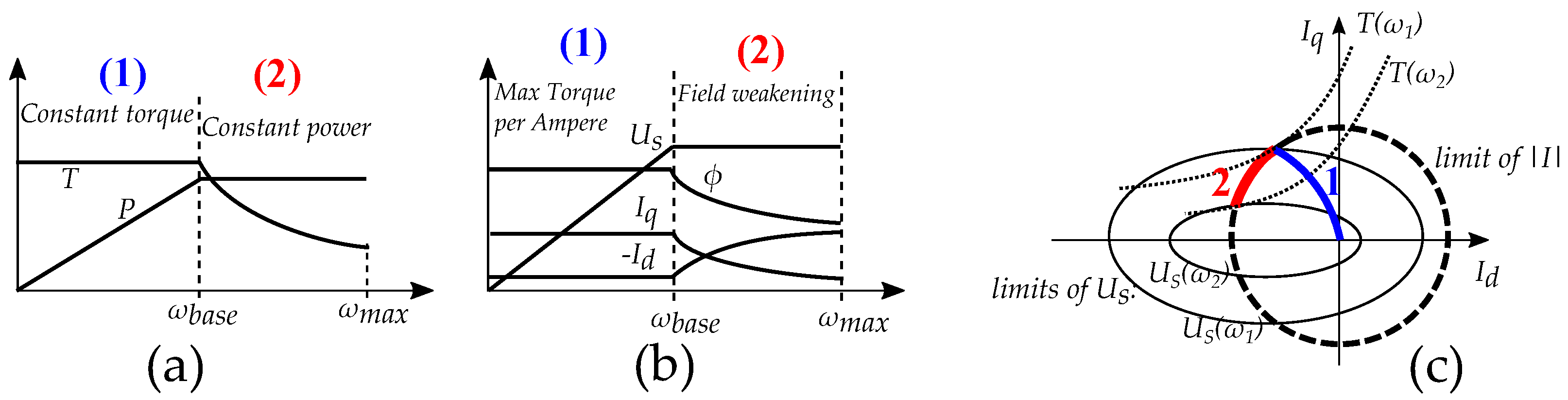
Figure 3.
Extended field weakening: (a) Increased torque by increased field current. (b) Increased max speed by decreased field current.
Figure 3.
Extended field weakening: (a) Increased torque by increased field current. (b) Increased max speed by decreased field current.

Figure 4.
Example of efficiency maps: (a,b) PMSM with a region of high efficiency, (c) compared to WRSM with the possibility of optimizing the flux.
Figure 4.
Example of efficiency maps: (a,b) PMSM with a region of high efficiency, (c) compared to WRSM with the possibility of optimizing the flux.
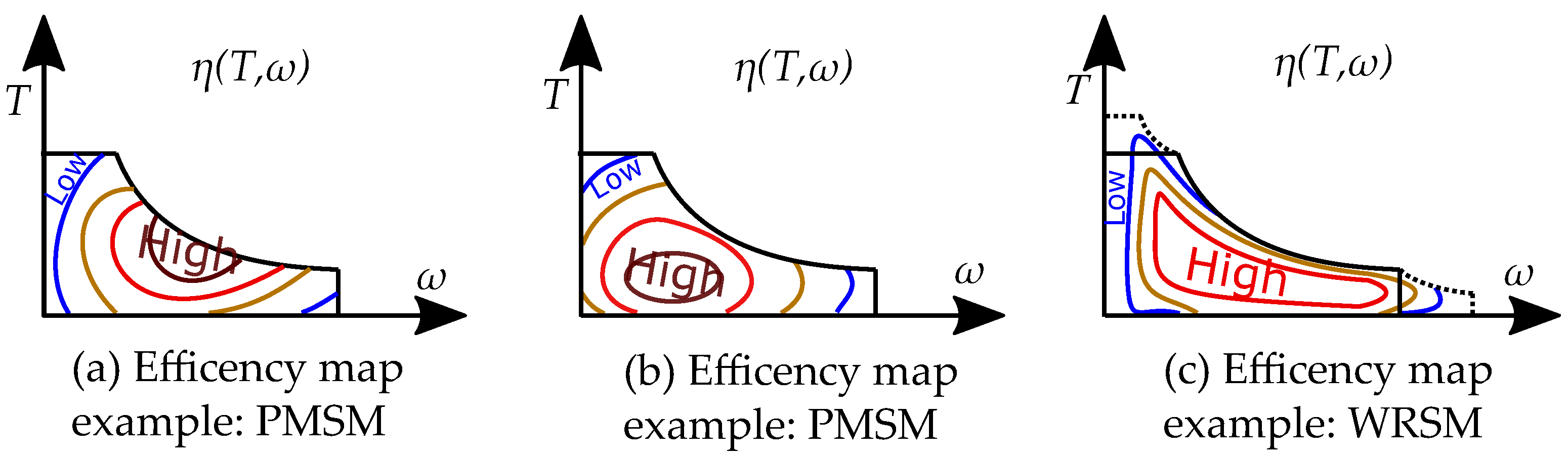
Figure 5.
Example of a variable efficiency map: (a) a region of high efficiency, which could be shifted by changing the torque–speed relation, either by a higher field current for a higher torque (b) or by a lower field current for a higher speed (c).
Figure 5.
Example of a variable efficiency map: (a) a region of high efficiency, which could be shifted by changing the torque–speed relation, either by a higher field current for a higher torque (b) or by a lower field current for a higher speed (c).
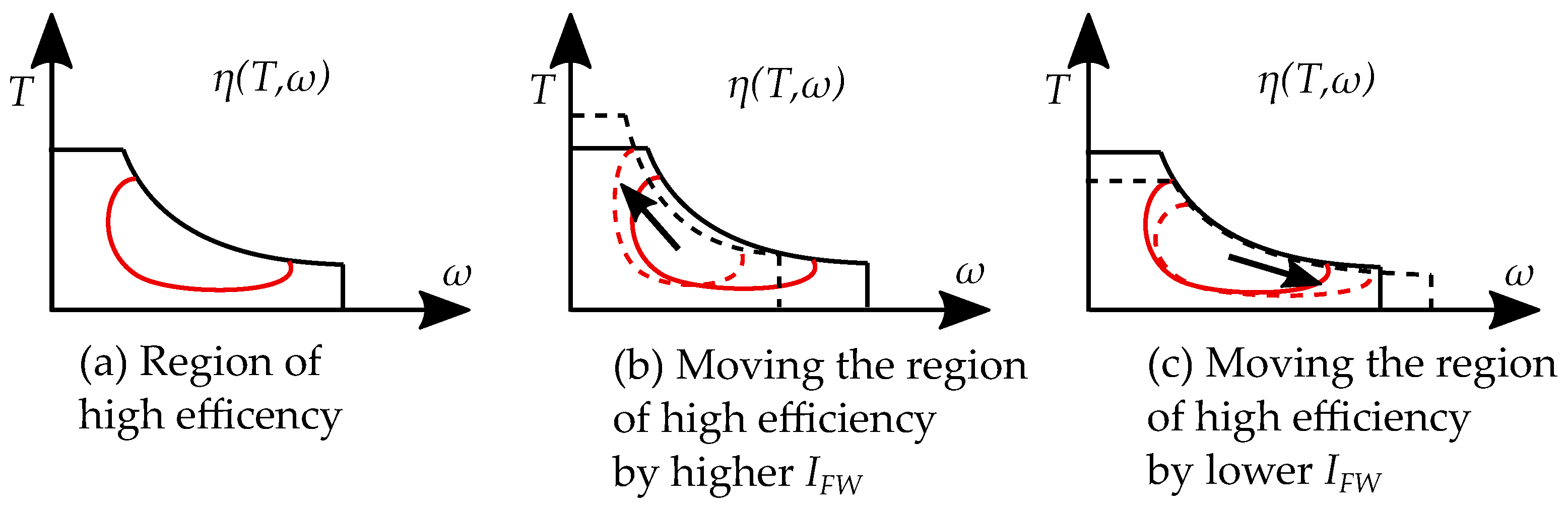
Figure 6.
(a) Generator connected with an inverter (b) Generator with a synchronous grid connection.
Figure 6.
(a) Generator connected with an inverter (b) Generator with a synchronous grid connection.
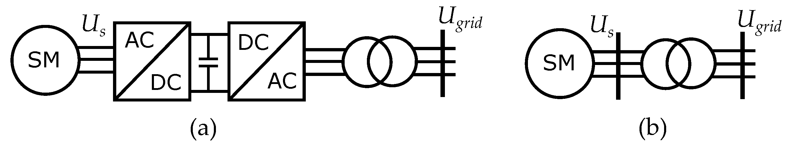
Figure 7.
(a) The rotor flux is variable by the field current. (b) The induced back EMF (rms) is controlled by the current of the field winding. (c) Unity power factor (d) Over excitation, high back EMF (e) Under excitation, low back EMF.
Figure 7.
(a) The rotor flux is variable by the field current. (b) The induced back EMF (rms) is controlled by the current of the field winding. (c) Unity power factor (d) Over excitation, high back EMF (e) Under excitation, low back EMF.
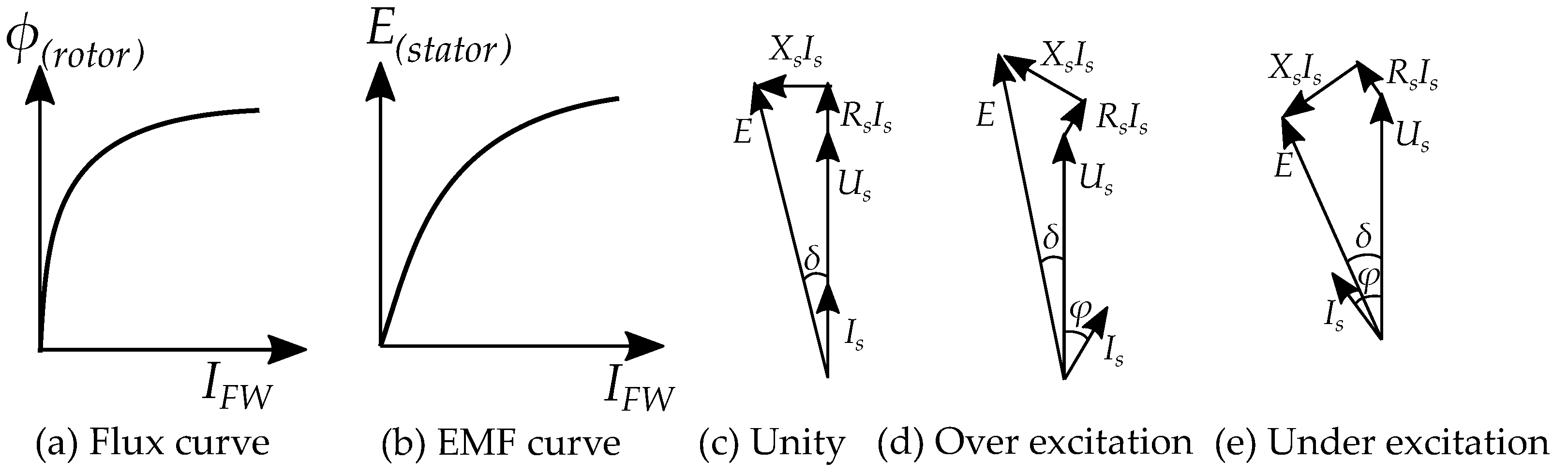
Figure 8.
Comparison of geometry of WRSM (a,b) and PMSM (c,d). The field windings (b) take up space within the rotor volume, compared to PM-based rotors (c).
Figure 8.
Comparison of geometry of WRSM (a,b) and PMSM (c,d). The field windings (b) take up space within the rotor volume, compared to PM-based rotors (c).
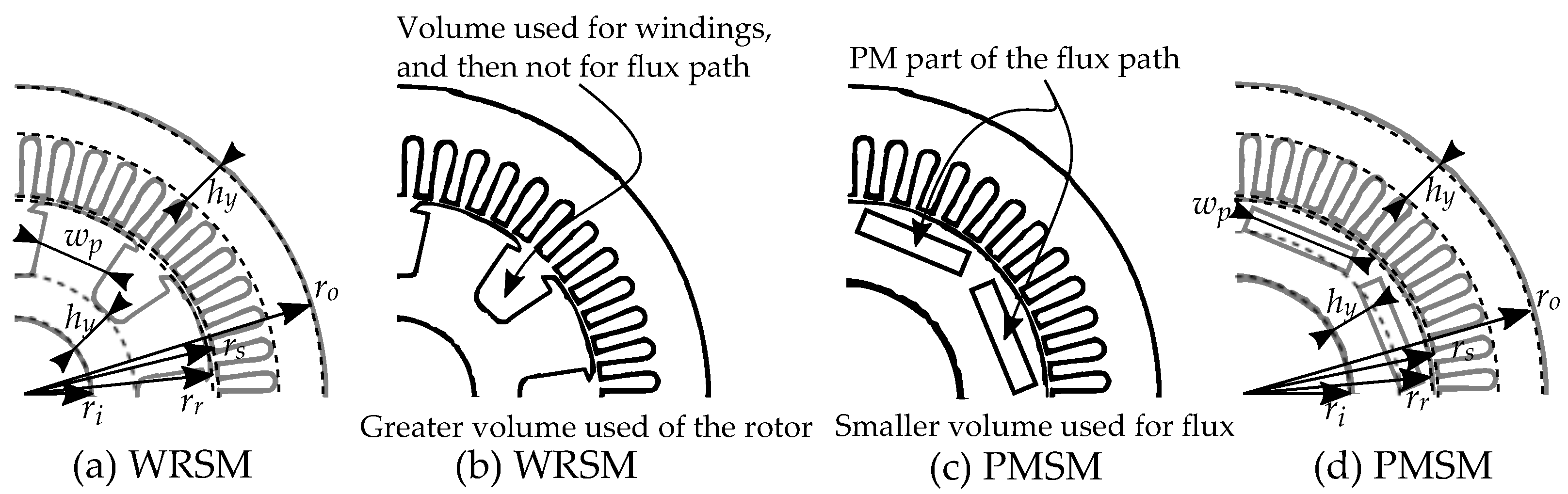
Figure 9.
Illustrative examples of applications: (a) Wind power generator (b) EV motor (c) Hydro power generator.
Figure 9.
Illustrative examples of applications: (a) Wind power generator (b) EV motor (c) Hydro power generator.
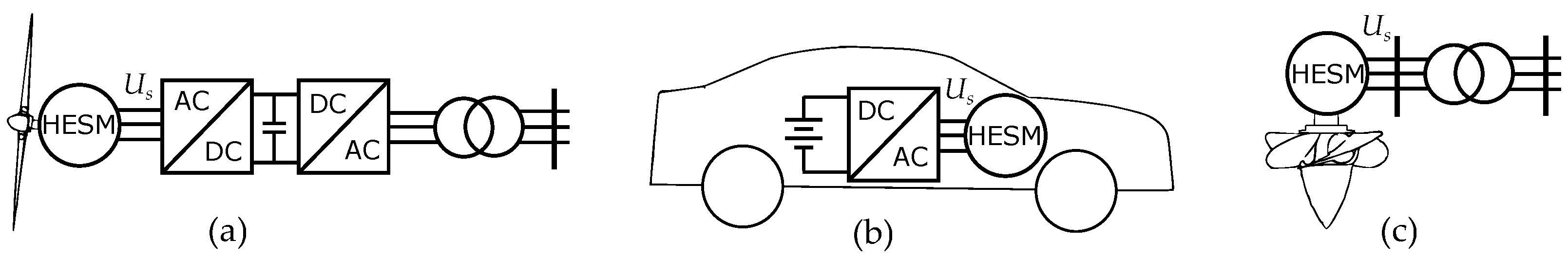
Figure 10.
Different ways of categorizing HE machines, and the different categories.
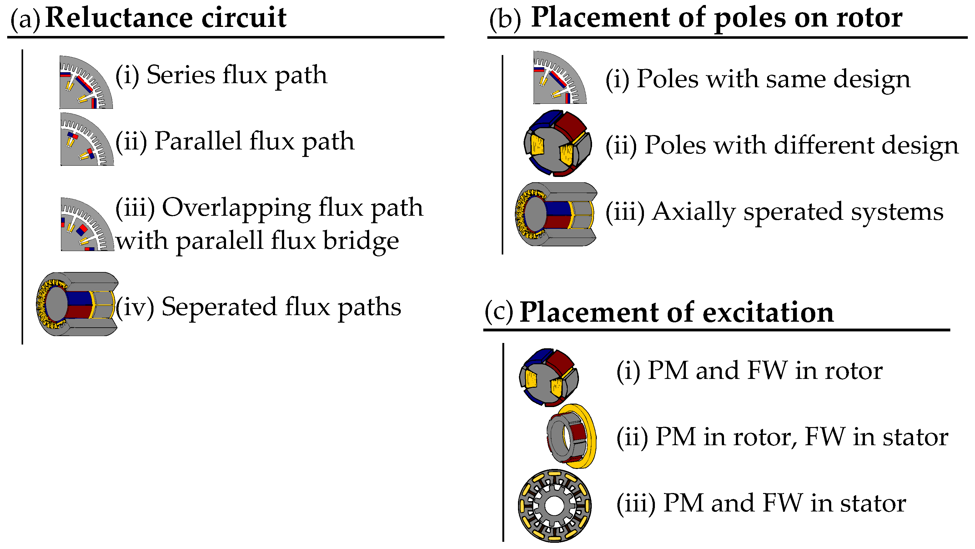
Figure 11.
Examples of basic designs built based on a “Series flux path design” (a) and a “Parallel flux path design” (c). Reluctance circuits for series (b) and parallel (d) flux paths.
Figure 11.
Examples of basic designs built based on a “Series flux path design” (a) and a “Parallel flux path design” (c). Reluctance circuits for series (b) and parallel (d) flux paths.
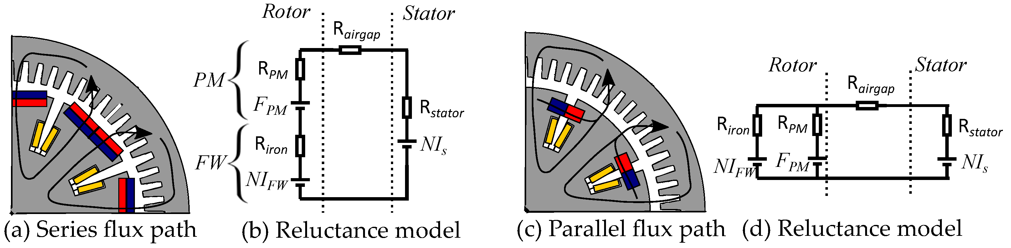
Figure 12.
The operation point of the curve in iron is different depending on the flux density (a). The permeability is only high (i.e., reluctance is low) for low flux densities (B). The permeability is instead low (i.e., reluctance is high) when the flux densities (B) operate near saturation. The permeability (and reluctance) is then similar to PMs (b).

Figure 13.
The flux path is similar for both low (a) and high (b) field currents in series flux paths. The resulting flux will be affected by the high reluctance of the PMs.
Figure 13.
The flux path is similar for both low (a) and high (b) field currents in series flux paths. The resulting flux will be affected by the high reluctance of the PMs.

Figure 14.
The magnetic circuit will be different depending on the DC current of the FW. (a) At high fields, the iron is saturated and all PM fluxes go to the stator. (b) At low field currents, there is a leakage flux from the PM through the iron of the electromagnets.
Figure 14.
The magnetic circuit will be different depending on the DC current of the FW. (a) At high fields, the iron is saturated and all PM fluxes go to the stator. (b) At low field currents, there is a leakage flux from the PM through the iron of the electromagnets.
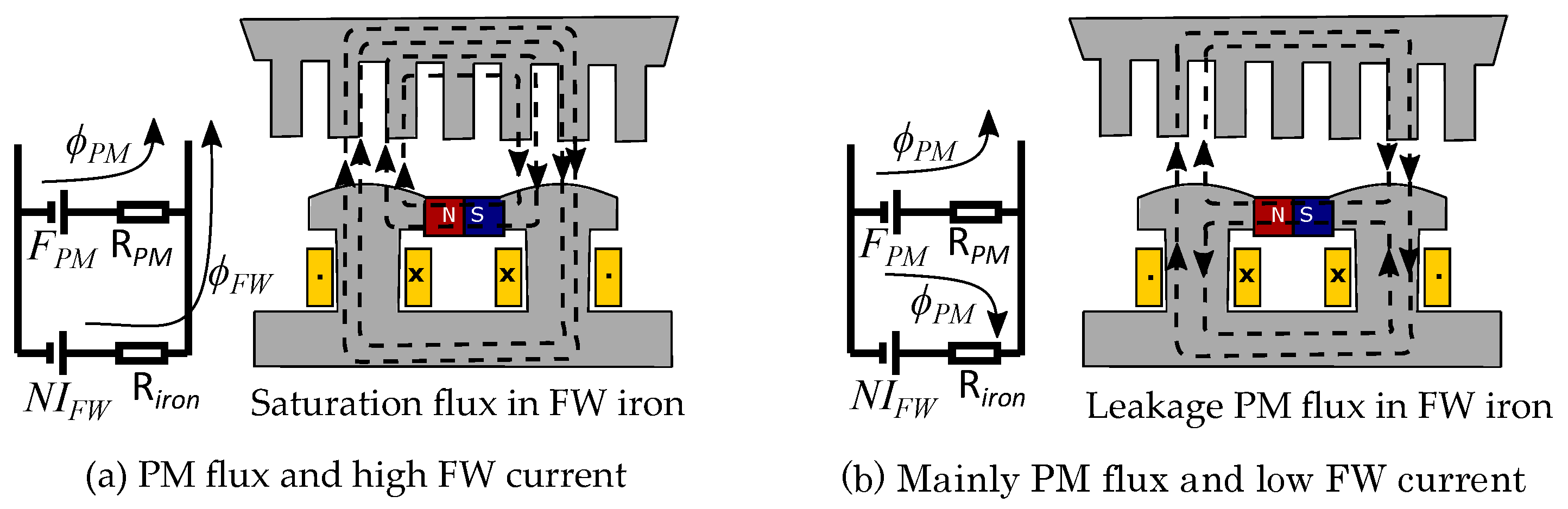
Figure 15.
(a) Example of series flux path with an iron flux bridge. The flux bridge adds low reluctance in parallel with the PM. (b) Reluctance model.
Figure 15.
(a) Example of series flux path with an iron flux bridge. The flux bridge adds low reluctance in parallel with the PM. (b) Reluctance model.
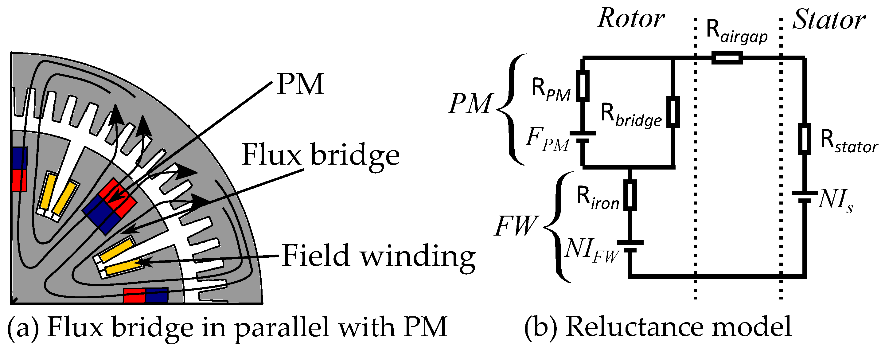
Figure 16.
A flux bridge designed in parallel with the PM. (a) It gives low reluctance for FW flux. (b) It also gives leakage paths for the PM flux when there is no FW flux.
Figure 16.
A flux bridge designed in parallel with the PM. (a) It gives low reluctance for FW flux. (b) It also gives leakage paths for the PM flux when there is no FW flux.

Figure 17.
(a) Parallel flux paths with separated flux paths combined by the same armature winding. (b) Reluctance model of separated two flux circuits for the same EMF.
Figure 17.
(a) Parallel flux paths with separated flux paths combined by the same armature winding. (b) Reluctance model of separated two flux circuits for the same EMF.

Figure 18.
Separated parts of rotor with a short auxiliary FW part (a) and a main PM part (b). These are combined at the rotor (c).
Figure 18.
Separated parts of rotor with a short auxiliary FW part (a) and a main PM part (b). These are combined at the rotor (c).
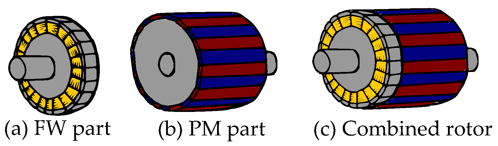
Figure 19.
The basic idea of axially separated systems. The rotor has one FW part and one PM part combined using the same armature winding in the stator.
Figure 19.
The basic idea of axially separated systems. The rotor has one FW part and one PM part combined using the same armature winding in the stator.

Figure 20.
A series flux path that can be constructed with different types of poles. Examples showing: (a) SPM, (b) IPM, (c) flux of the pole pairs (IPM).
Figure 20.
A series flux path that can be constructed with different types of poles. Examples showing: (a) SPM, (b) IPM, (c) flux of the pole pairs (IPM).

Figure 21.
Variable flux and changing number of pole pairs: (a) six poles, (b) without field current, (c) two poles.
Figure 21.
Variable flux and changing number of pole pairs: (a) six poles, (b) without field current, (c) two poles.
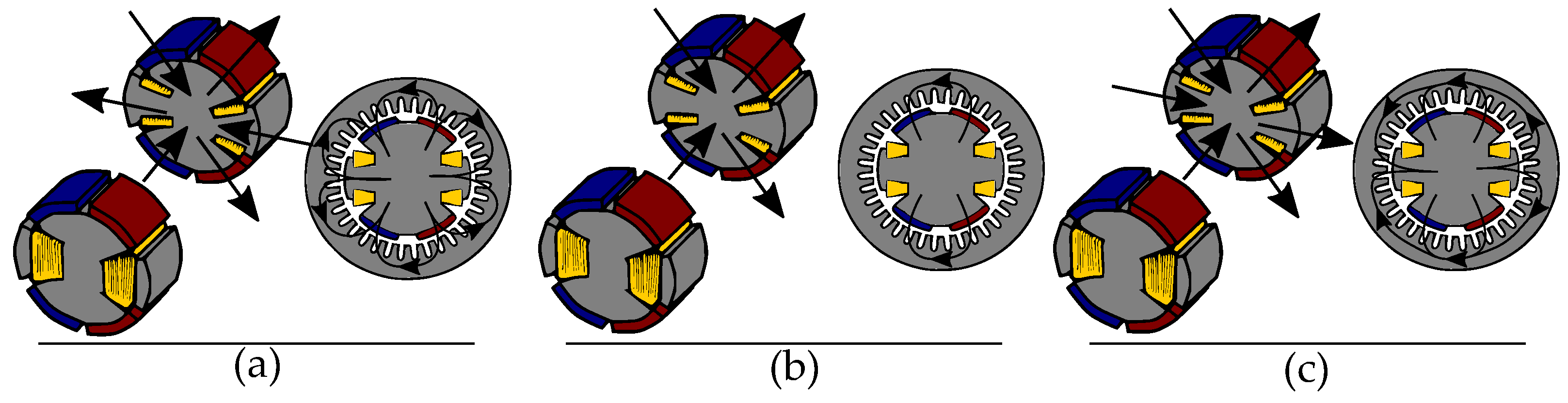
Figure 22.
Rotors of various designs with different types of rotors distributed around the circumference.
Figure 22.
Rotors of various designs with different types of rotors distributed around the circumference.
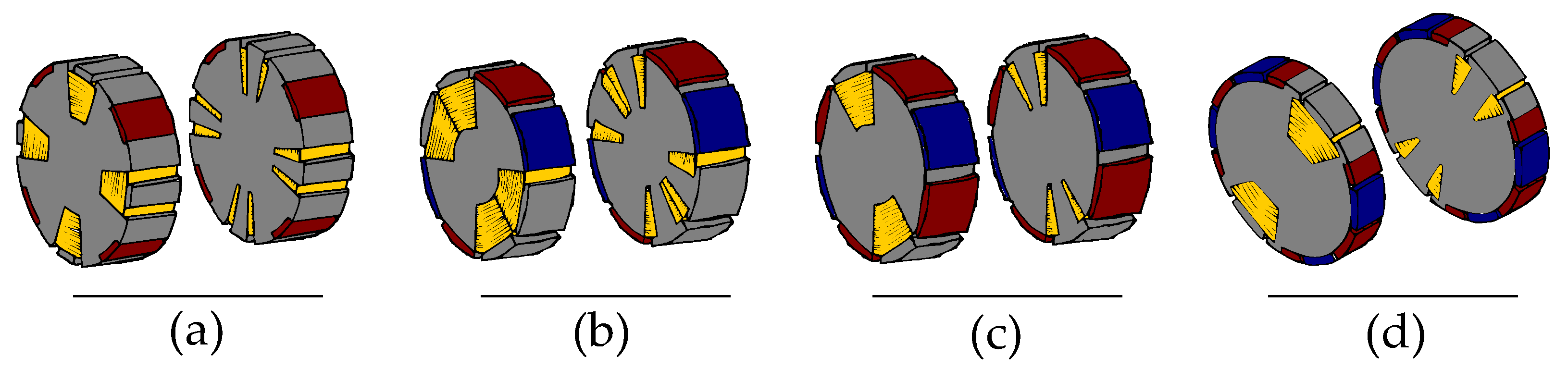
Figure 23.
Excitation system: Pilot and slip rings (a) Rectifier and slip rings (b) Brushless (c). Some alternatives have the FW in the stator (d).
Figure 23.
Excitation system: Pilot and slip rings (a) Rectifier and slip rings (b) Brushless (c). Some alternatives have the FW in the stator (d).
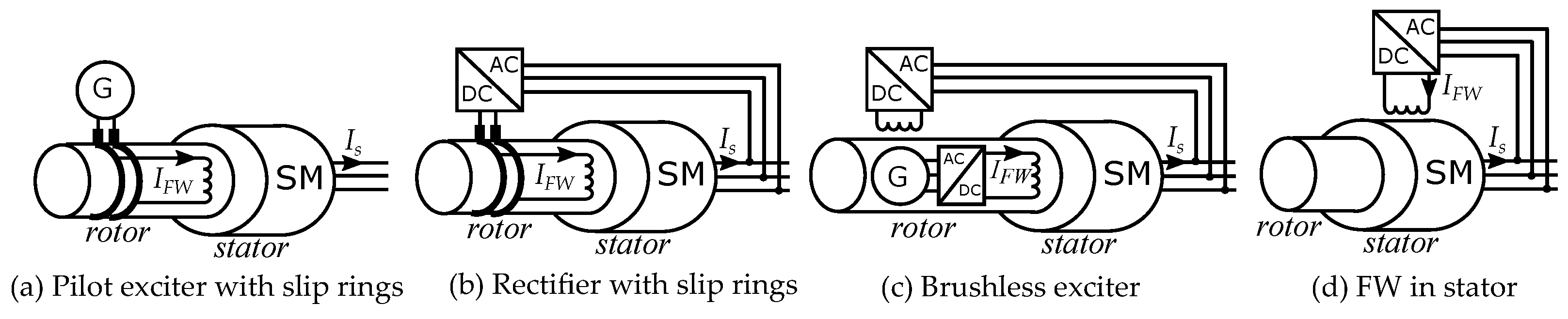
Figure 24.
(a) Consequent pole rotor with PMS an with the FW in stator. (b) A consequent pole rotor only has PMs on half of the pole pairs; the other half are made of iron. (c) the FW induce a magnetic flux orthogonal to the PM flux. (d) The PM flux is distributed in the radial-tangential plane. (e) The FW flux is distributed in the radial-axial plane, such that the iron poles can be affected by the field current.
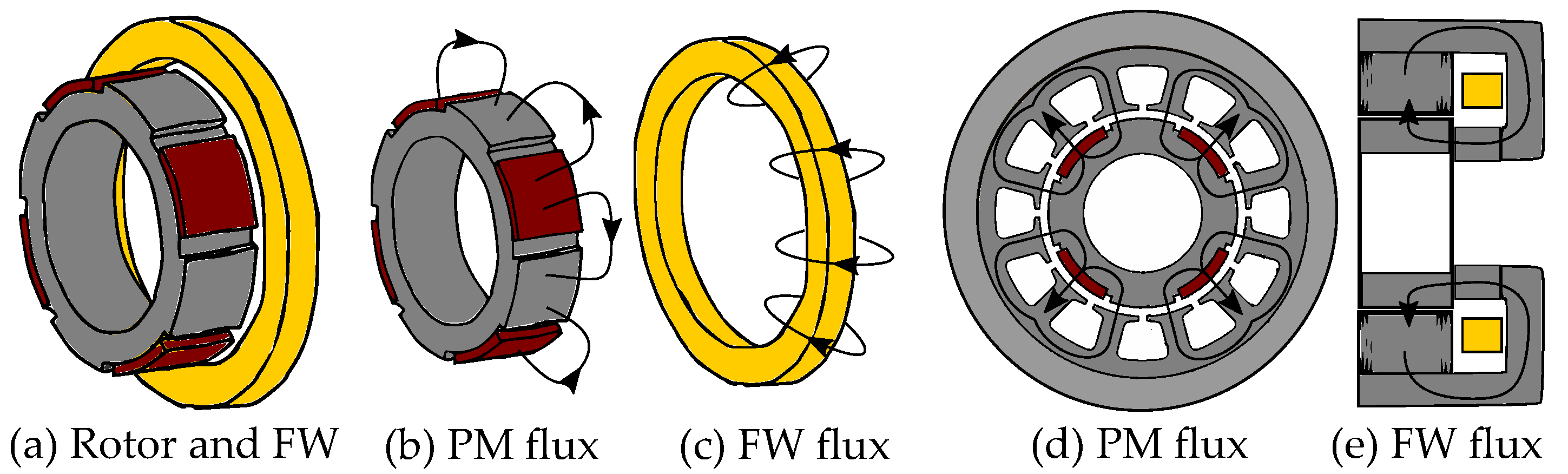
Figure 25.
Hybrid excitation concept built as two axially separated consequent pole rotors(a), with the PM flux in the radial-tangential plane (b). The FW flux is in the radial-axial plane (c), so the field current could affect the “iron poles” (d).
Figure 25.
Hybrid excitation concept built as two axially separated consequent pole rotors(a), with the PM flux in the radial-tangential plane (b). The FW flux is in the radial-axial plane (c), so the field current could affect the “iron poles” (d).

Figure 26.
Different designs with two axial segments of consequent pole machines.

Figure 27.
(a) Spoke-type rotors are similar to consequent poles since they both have iron pole shoes toward the air gap. (b) The flux each pole pair is in the radial-tangential plane. (c) The iron pole shoes could be affected by a FW in the stator.
Figure 27.
(a) Spoke-type rotors are similar to consequent poles since they both have iron pole shoes toward the air gap. (b) The flux each pole pair is in the radial-tangential plane. (c) The iron pole shoes could be affected by a FW in the stator.
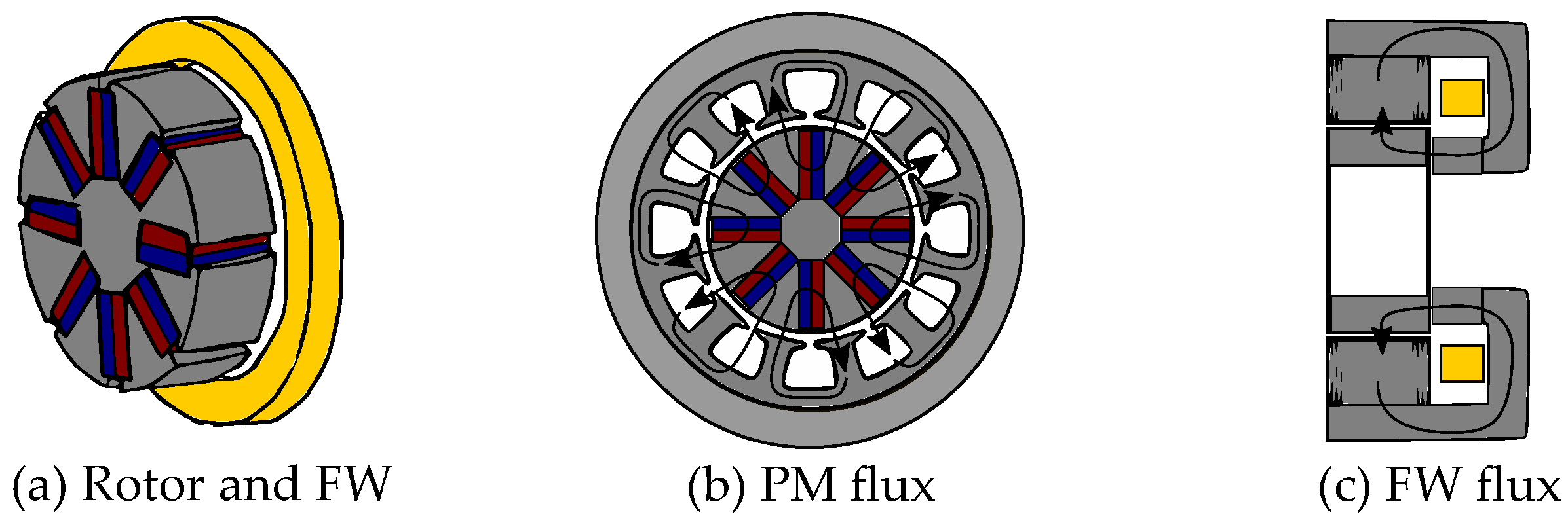
Figure 28.
Flux-switching machines with hybrid excitation. The rotor is only iron and the excitation system is entirely in the stator.
Figure 28.
Flux-switching machines with hybrid excitation. The rotor is only iron and the excitation system is entirely in the stator.

Figure 29.
Generator with excitation system placed in the stator. The flux takes a different path through the rotor depending on the rotor angle.
Figure 29.
Generator with excitation system placed in the stator. The flux takes a different path through the rotor depending on the rotor angle.
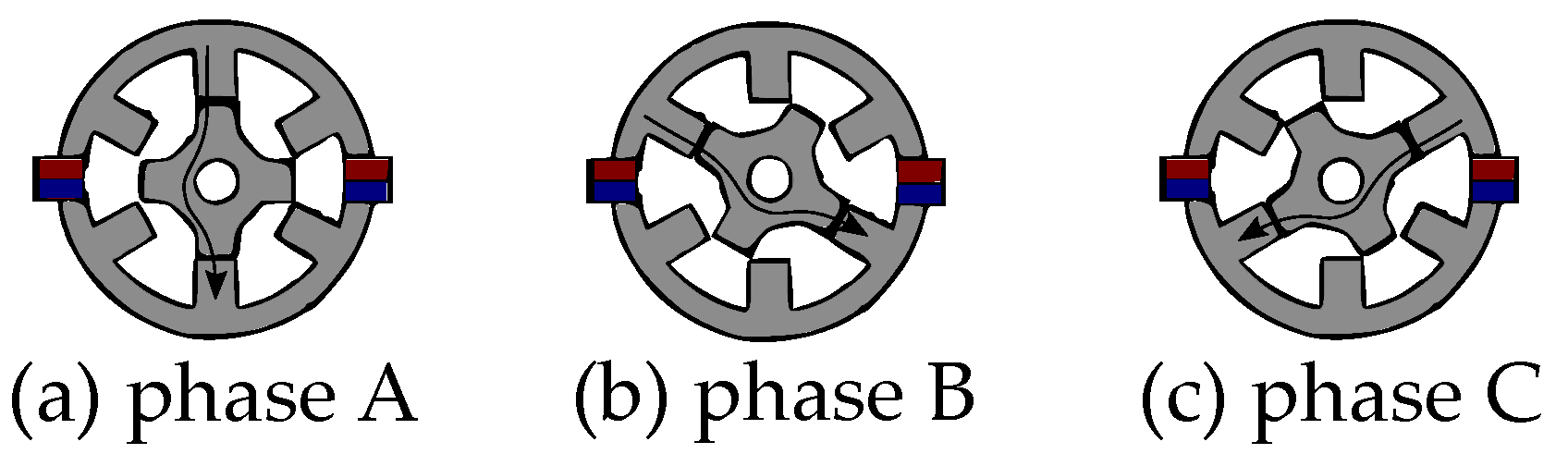
Figure 30.
Claw-pole rotor. (a) The flux from the coil goes through the two claw-shaped parts into the claw poles. (b) One claw-shaped part becomes the North pole and the other becomes the South pole. (c) The flux goes through the stator iron between the poles.
Figure 30.
Claw-pole rotor. (a) The flux from the coil goes through the two claw-shaped parts into the claw poles. (b) One claw-shaped part becomes the North pole and the other becomes the South pole. (c) The flux goes through the stator iron between the poles.
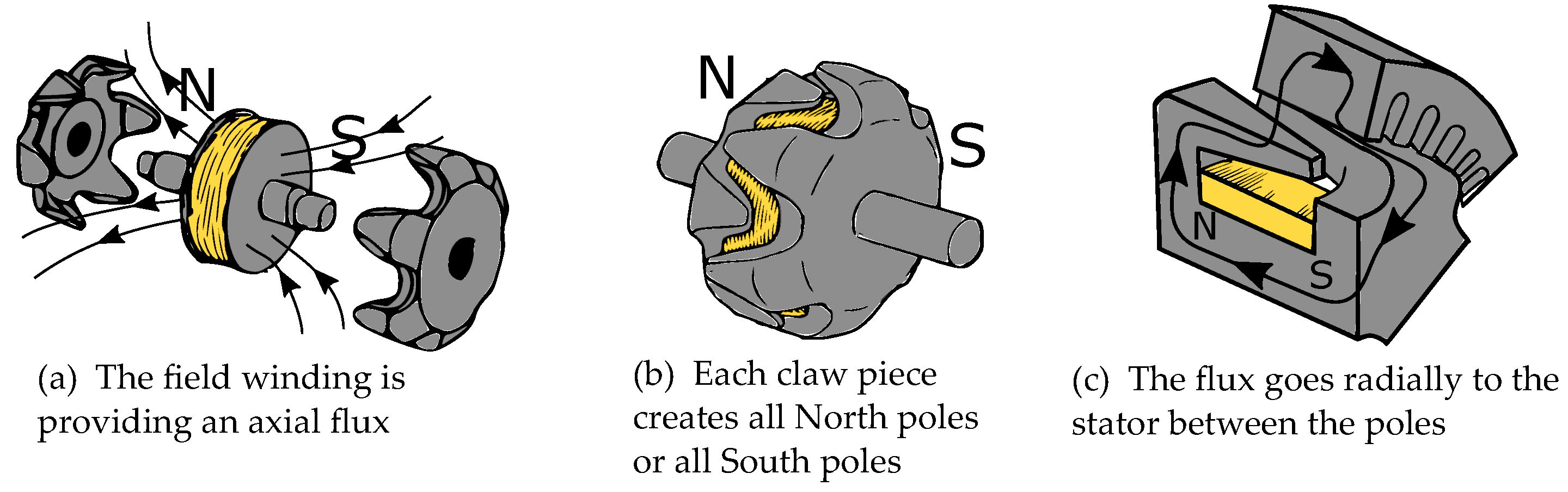
Figure 31.
HE concepts for claw-pole machines: (a) PM between poles, (b) PM within the field winding (c) PM in rotor and field winding in stator.
Figure 31.
HE concepts for claw-pole machines: (a) PM between poles, (b) PM within the field winding (c) PM in rotor and field winding in stator.


Table 1.
Density (m/V) of some materials used in electrical machines.
| Material | Density [g/cm3] | Application |
|---|---|---|
| Steel | 7.85 | Soft magn. core |
| Steel (0.03 Si) | 7.65 | Soft magn. core |
| Iron | 7.86 | Soft magn. core |
| NdFeB | 7.3–7.7 | PM |
| SmCo | 7.3–7.7 | PM |
| Hard Ferrite | 4.9–5.1 | PM |
| Copper | 8.96 | Conductor |
| Aluminum | 2.7 | Conductor |
Table 2.
Remanent flux density (at 25 °C), Coercive field strength and Curie Temperature of some common PM materials.
Table 2.
Remanent flux density (at 25 °C), Coercive field strength and Curie Temperature of some common PM materials.
| Material | (25 °C) [T] | [kA/m] | [°C] |
|---|---|---|---|
| Sr Ferrite | 0.39 | 275 | 733 |
| SmCo5 | 0.90 | 1700 | 691 |
| Sm2Co17 | 1.07 | 1100 | 805 |
| Alnico 5 | 1.28 | 55 | 840 |
| NdFeB | 1.38 | 1000 | 310 |
Table 3.
Resistivity of conductor materials and the material density.
| Material | Resistivity [m] | Density [g/cm3] |
|---|---|---|
| Copper | 1.72 | 8.96 |
| Aluminum | 2.65 | 2.7 |
Table 4.
Permeability of soft magnetic materials.
| Permeability | Permeability | |
|---|---|---|
| Material | Regular fields | Above saturation |
| Iron | 10,000–200,000 | 1 |
| Elec. Steel (0.03 Si) | 4000–100,000 | 1 |
Table 5.
Relative recoil permeability for PM.
| Material | Permeability |
|---|---|
| NdFeB | 1.0–1.1 |
| SmCo | 1.0–1.1 |
| Ferrite | 1.05–1.2 |
| Alnico | 1.3–6.2 |
Publisher’s Note: MDPI stays neutral with regard to jurisdictional claims in published maps and institutional affiliations. |
© 2022 by the authors. Licensee MDPI, Basel, Switzerland. This article is an open access article distributed under the terms and conditions of the Creative Commons Attribution (CC BY) license (https://creativecommons.org/licenses/by/4.0/).
Share and Cite
MDPI and ACS Style
Mörée, G.; Leijon, M. Overview of Hybrid Excitation in Electrical Machines. Energies 2022, 15, 7254. https://doi.org/10.3390/en15197254
AMA Style
Mörée G, Leijon M. Overview of Hybrid Excitation in Electrical Machines. Energies. 2022; 15(19):7254. https://doi.org/10.3390/en15197254
Chicago/Turabian StyleMörée, Gustav, and Mats Leijon. 2022. "Overview of Hybrid Excitation in Electrical Machines" Energies 15, no. 19: 7254. https://doi.org/10.3390/en15197254
Note that from the first issue of 2016, this journal uses article numbers instead of page numbers. See further details here.