Author Contributions
Conceptualization, K.K. (Krzysztof Kurec), K.K. (Konrad Kamieniecki) and J.P.; methodology, K.K. (Krzysztof Kurec), K.K. (Konrad Kamieniecki) and J.P.; software, K.K. (Krzysztof Kurec), K.K. (Konrad Kamieniecki); validation, K.K. (Krzysztof Kurec); formal analysis, K.K. (Krzysztof Kurec), K.K. (Konrad Kamieniecki) and J.P.; investigation, K.K. (Krzysztof Kurec), K.K. (Konrad Kamieniecki) and J.P.; resources, K.K. (Krzysztof Kurec), K.K. (Konrad Kamieniecki) and J.P.; data curation, K.K. (Krzysztof Kurec), K.K. (Konrad Kamieniecki); writing—original draft preparation, K.K. (Krzysztof Kurec); writing—review and editing, K.K. (Konrad Kamieniecki) and J.P.; visualization, K.K. (Krzysztof Kurec); supervision, J.P. All authors have read and agreed to the published version of the manuscript.
Figure 1.
BMW Lovos concept by Anne Forschner with (
a) closed scales and (
b) opened scales. Images courtesy of Anne Forschner [
8].
Figure 1.
BMW Lovos concept by Anne Forschner with (
a) closed scales and (
b) opened scales. Images courtesy of Anne Forschner [
8].
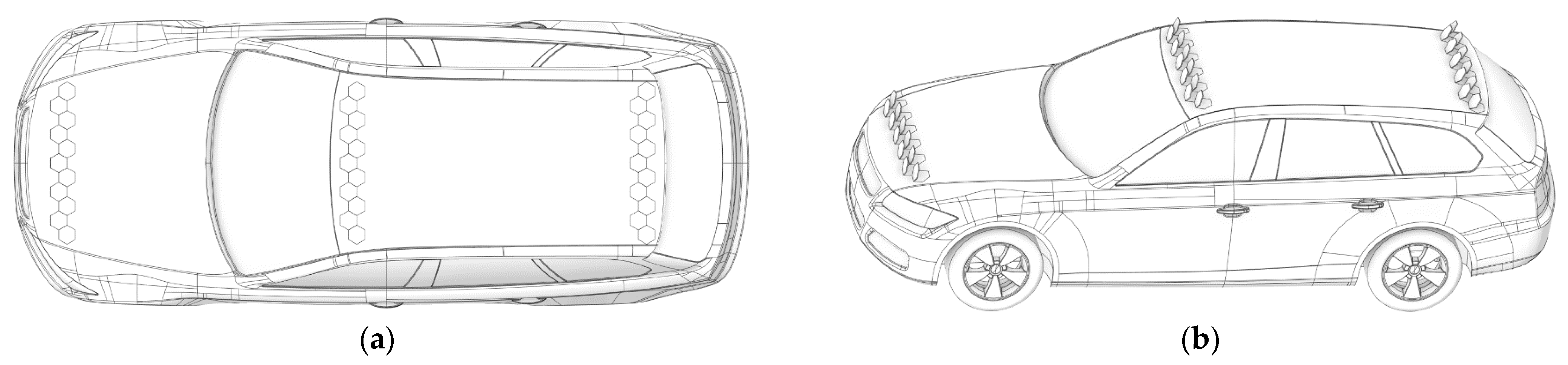
Figure 2.
The DrivAer model with two sets of rows of hexagonal flaps mounted at the front edge of the hood, the front edge of the roof, and the rear edge of the roof: (a) top view with flaps inactive; (b) side view with plates ejected at an angle equal to 60°.
Figure 2.
The DrivAer model with two sets of rows of hexagonal flaps mounted at the front edge of the hood, the front edge of the roof, and the rear edge of the roof: (a) top view with flaps inactive; (b) side view with plates ejected at an angle equal to 60°.
Figure 3.
(a) Flaps covering the roof of the DrivAer model. Single flap rotated with its intermediate positions where it either ejects towards (b) the left side of the car or its (c) right side. Flaps are shown (d) while adjusting and (e) when rotated into the final position when they pose the maximum aerodynamic drag.
Figure 4.
Mesh at the symmetry plane (a) wide of view and (b) close-up on the car.
Figure 4.
Mesh at the symmetry plane (a) wide of view and (b) close-up on the car.
Figure 5.
Values of (a) drag force coefficient and (b) lift force coefficients for different grid sizes used in calculations.
Figure 5.
Values of (a) drag force coefficient and (b) lift force coefficients for different grid sizes used in calculations.
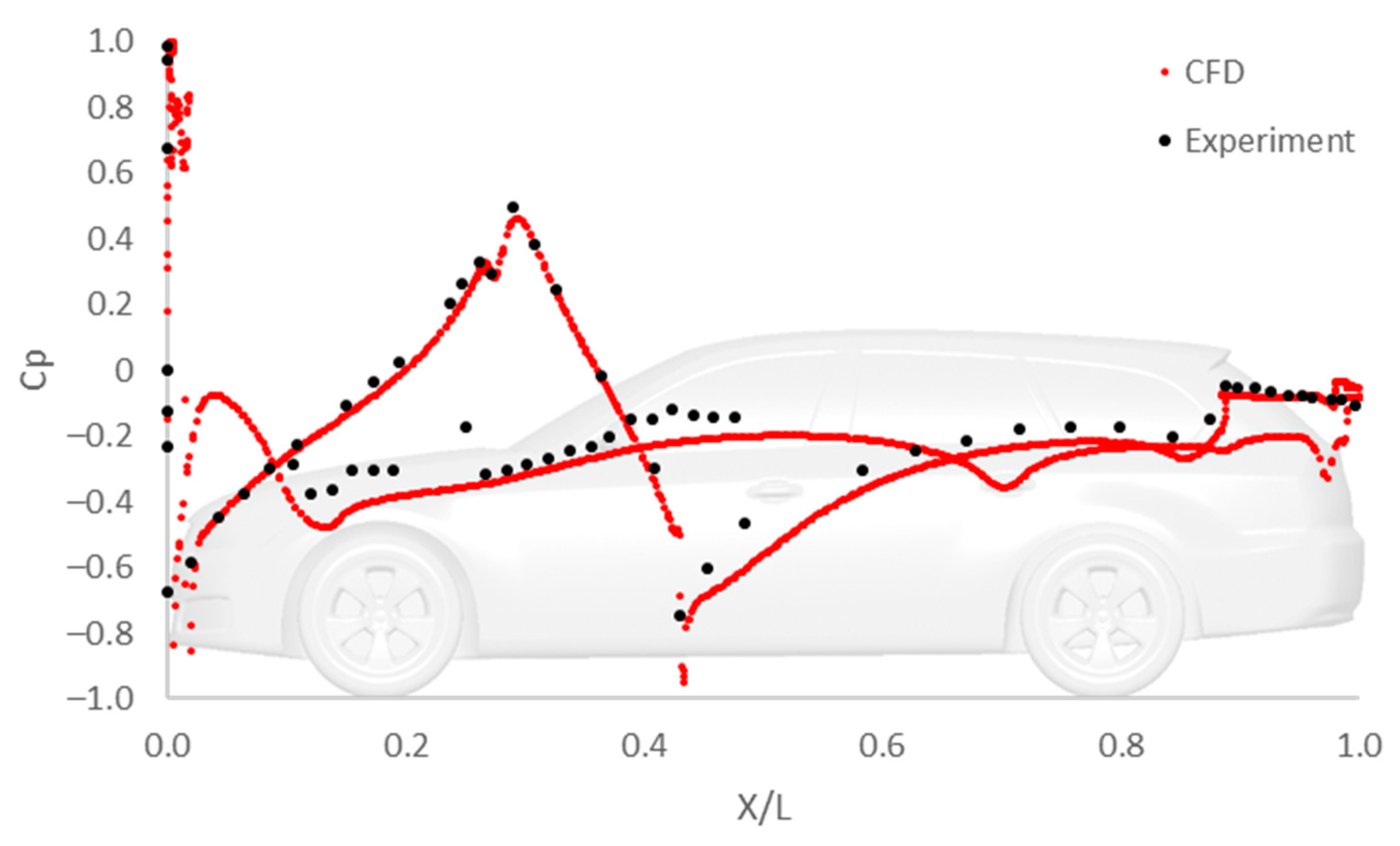
Figure 6.
Pressure coefficient distribution along the car body at the symmetry plane compared with the experiment [
16].
Figure 6.
Pressure coefficient distribution along the car body at the symmetry plane compared with the experiment [
16].
Figure 7.
Comparison of contours of velocity normalized by velocity in the free stream from (
a) PIV [
17] and (
b) CFD.
Figure 7.
Comparison of contours of velocity normalized by velocity in the free stream from (
a) PIV [
17] and (
b) CFD.
Figure 8.
Velocity contours [m/s] on the symmetry plane: (a) base case; (b) rear spoiler; (c) front spoiler; (d) rear and front spoiler.
Figure 8.
Velocity contours [m/s] on the symmetry plane: (a) base case; (b) rear spoiler; (c) front spoiler; (d) rear and front spoiler.
Figure 9.
Pressure coefficient contours on the car body: (a) base case; (b) rear spoiler; (c) front spoiler; (d) rear and front spoiler.
Figure 9.
Pressure coefficient contours on the car body: (a) base case; (b) rear spoiler; (c) front spoiler; (d) rear and front spoiler.
Figure 10.
Velocity contours [m/s] on the symmetry plane: (a) base case; (b) hood spoiler 0.33 m; (c) hood spoiler 0.66 m; (d) hood spoiler 0.99 m.
Figure 10.
Velocity contours [m/s] on the symmetry plane: (a) base case; (b) hood spoiler 0.33 m; (c) hood spoiler 0.66 m; (d) hood spoiler 0.99 m.
Figure 11.
Pressure coefficient contours on the car body: (a) base case; (b) hood spoiler 0.33 m; (c) hood spoiler 0.66 m; (d) hood spoiler 0.99 m.
Figure 11.
Pressure coefficient contours on the car body: (a) base case; (b) hood spoiler 0.33 m; (c) hood spoiler 0.66 m; (d) hood spoiler 0.99 m.
Figure 12.
Velocity contours [m/s] on the symmetry plane and the offset of the roof surface in the middle of the plates, for the plates creating a “V” pattern on the roof, inclined at: (a) 45° and (b) 90°.
Figure 12.
Velocity contours [m/s] on the symmetry plane and the offset of the roof surface in the middle of the plates, for the plates creating a “V” pattern on the roof, inclined at: (a) 45° and (b) 90°.
Figure 13.
Pressure coefficient contours on the car body for the plates creating a “V” pattern on the roof, inclined at (a) 45° and (b) 90°.
Figure 13.
Pressure coefficient contours on the car body for the plates creating a “V” pattern on the roof, inclined at (a) 45° and (b) 90°.
Figure 14.
Velocity contours [m/s] on the symmetry plane and the offset of the roof surface in the middle of the plates, for the plates creating an “A” pattern on the roof, inclined at: (a) 45° and (b) 90°.
Figure 14.
Velocity contours [m/s] on the symmetry plane and the offset of the roof surface in the middle of the plates, for the plates creating an “A” pattern on the roof, inclined at: (a) 45° and (b) 90°.
Figure 15.
Pressure coefficient contours on the car body for the plates creating an “A” pattern on the roof, inclined at (a) 45° and (b) 90°.
Figure 15.
Pressure coefficient contours on the car body for the plates creating an “A” pattern on the roof, inclined at (a) 45° and (b) 90°.
Figure 16.
Velocity contours [m/s] on the symmetry plane and the offset of the hood surface in the middle of the plates, for the plates creating a “V” pattern on the hood, inclined at (a) 45° and (b) 90°.
Figure 16.
Velocity contours [m/s] on the symmetry plane and the offset of the hood surface in the middle of the plates, for the plates creating a “V” pattern on the hood, inclined at (a) 45° and (b) 90°.
Figure 17.
Pressure coefficient contours on the car body for the plates creating a “V” pattern on the hood, inclined at (a) 45° and (b) 90°.
Figure 17.
Pressure coefficient contours on the car body for the plates creating a “V” pattern on the hood, inclined at (a) 45° and (b) 90°.
Figure 18.
Velocity contours [m/s] on the symmetry plane and the offset of the hood surface in the middle of the plates, for the plates creating an “A” pattern on the hood, inclined at (a) 45° and (b) 90°.
Figure 18.
Velocity contours [m/s] on the symmetry plane and the offset of the hood surface in the middle of the plates, for the plates creating an “A” pattern on the hood, inclined at (a) 45° and (b) 90°.
Figure 19.
Pressure coefficient contours on the car body for the plates creating an “A” pattern on the hood, inclined at (a) 45° and (b) 90°.
Figure 19.
Pressure coefficient contours on the car body for the plates creating an “A” pattern on the hood, inclined at (a) 45° and (b) 90°.
Figure 20.
Velocity contours [m/s] on the symmetry plane and the offsets of the hood and the roof surfaces in the middle of the plates, for the plates creating a “V” pattern on the hood and the roof, inclined at (a) 45° and (b) 90°.
Figure 20.
Velocity contours [m/s] on the symmetry plane and the offsets of the hood and the roof surfaces in the middle of the plates, for the plates creating a “V” pattern on the hood and the roof, inclined at (a) 45° and (b) 90°.
Figure 21.
Pressure coefficient contours on the car body for the plates creating a “V” pattern on the hood and the roof, inclined at (a) 45° and (b) 90°.
Figure 21.
Pressure coefficient contours on the car body for the plates creating a “V” pattern on the hood and the roof, inclined at (a) 45° and (b) 90°.
Figure 22.
Velocity contours [m/s] on the symmetry plane and the offsets of the hood and the roof surfaces in the middle of the plates, for the plates creating an “A” pattern on the hood and the roof, inclined at (a) 45° and (b) 90°.
Figure 22.
Velocity contours [m/s] on the symmetry plane and the offsets of the hood and the roof surfaces in the middle of the plates, for the plates creating an “A” pattern on the hood and the roof, inclined at (a) 45° and (b) 90°.
Figure 23.
Pressure coefficient contours on the car body for the plates creating an “A” pattern on the hood and the roof, inclined at (a) 45° and (b) 90°.
Figure 23.
Pressure coefficient contours on the car body for the plates creating an “A” pattern on the hood and the roof, inclined at (a) 45° and (b) 90°.
Table 1.
Aerodynamic coefficients from experiments and CFD.
Table 1.
Aerodynamic coefficients from experiments and CFD.
| Case | Drag Coefficient | Lift Coefficient |
|---|
| Experiment | 0.294 | −0.120 |
| CFD | 0.259 | −0.116 |
Table 2.
Aerodynamic coefficients for different locations of the roof spoiler.
Table 2.
Aerodynamic coefficients for different locations of the roof spoiler.
| Case | Drag Coefficient | Lift Coefficient | Lift Distribution |
|---|
| Front | Rear |
|---|
| Base | 0.259 | −0.116 | −0.147 | 0.031 |
| Rear spoiler | 0.402 | −0.328 | −0.138 | −0.190 |
| Front spoiler | 0.359 | 0.051 | −0.011 | 0.062 |
| Rear and front spoilers | 0.397 | −0.192 | −0.111 | −0.081 |
Table 3.
Aerodynamic coefficients for different locations of the hood spoiler.
Table 3.
Aerodynamic coefficients for different locations of the hood spoiler.
| Case | Drag Coefficient | Lift Coefficient | Lift Distribution |
|---|
| Front | Rear |
|---|
| Base | 0.259 | −0.116 | −0.147 | 0.031 |
| Hood spoiler 0.33 m | 0.304 | −0.156 | −0.083 | −0.072 |
| Hood spoiler 0.66 m | 0.291 | −0.122 | −0.069 | −0.053 |
| Hood spoiler 0.99 m | 0.278 | −0.110 | −0.069 | −0.041 |
Table 4.
Aerodynamic coefficients for flaps creating a “V” pattern on the roof.
Table 4.
Aerodynamic coefficients for flaps creating a “V” pattern on the roof.
| Case | Drag Coefficient | Lift Coefficient | Lift Distribution |
|---|
| Front | Rear |
|---|
| Base | 0.259 | −0.116 | −0.147 | 0.031 |
| Rear spoiler | 0.402 | −0.328 | −0.138 | −0.190 |
| Roof “V” pattern 45° | 0.433 | −0.241 | −0.106 | −0.135 |
| Roof “V” pattern 90° | 0.517 | −0.320 | −0.128 | −0.193 |
Table 5.
Aerodynamic coefficients for flaps creating an “A” pattern on the roof.
Table 5.
Aerodynamic coefficients for flaps creating an “A” pattern on the roof.
| Case | Drag Coefficient | Lift Coefficient | Lift Distribution |
|---|
| Front | Rear |
|---|
| Base | 0.259 | −0.116 | −0.147 | 0.031 |
| Rear spoiler | 0.402 | −0.328 | −0.138 | −0.190 |
| Roof “A” pattern 45° | 0.474 | −0.232 | −0.078 | −0.154 |
| Roof “A” pattern 90° | 0.554 | −0.247 | −0.080 | −0.168 |
Table 6.
Aerodynamic coefficients for flaps creating a “V” pattern on the hood.
Table 6.
Aerodynamic coefficients for flaps creating a “V” pattern on the hood.
| Case | Drag Coefficient | Lift Coefficient | Lift Distribution |
|---|
| Front | Rear |
|---|
| Base | 0.259 | −0.116 | −0.147 | 0.031 |
| Hood spoiler 0.33 m | 0.304 | −0.156 | −0.083 | −0.072 |
| Hood “V” pattern 45° | 0.293 | −0.122 | −0.070 | −0.052 |
| Hood “V” pattern 90° | 0.337 | −0.134 | −0.069 | −0.065 |
Table 7.
Aerodynamic coefficients for flaps creating an “A” pattern on the hood.
Table 7.
Aerodynamic coefficients for flaps creating an “A” pattern on the hood.
| Case | Drag Coefficient | Lift Coefficient | Lift Distribution |
|---|
| Front | Rear |
|---|
| Base | 0.259 | −0.116 | −0.147 | 0.031 |
| Hood spoiler 0.33 m | 0.304 | −0.156 | −0.083 | −0.072 |
| Hood “A” pattern 45° | 0.292 | −0.091 | −0.050 | −0.041 |
| Hood “A” pattern 90° | 0.323 | 0.018 | 0.027 | −0.009 |
Table 8.
Aerodynamic coefficients for flaps creating a “V” pattern on the roof and the hood.
Table 8.
Aerodynamic coefficients for flaps creating a “V” pattern on the roof and the hood.
| Case | Drag Coefficient | Lift Coefficient | Lift Distribution |
|---|
| Front | Rear |
|---|
| Base | 0.259 | −0.116 | −0.147 | 0.031 |
| Roof “V” pattern 90° | 0.517 | −0.320 | −0.128 | −0.193 |
| Hood “V” pattern 90° | 0.337 | −0.134 | −0.069 | −0.065 |
| Hood + Roof “V” pattern 45° | 0.453 | −0.216 | −0.093 | −0.123 |
| Hood + Roof “V” pattern 90° | 0.609 | −0.377 | −0.126 | −0.251 |
Table 9.
Aerodynamic coefficients for flaps creating an “A” pattern on the roof and the hood.
Table 9.
Aerodynamic coefficients for flaps creating an “A” pattern on the roof and the hood.
| Case | Drag Coefficient | Lift Coefficient | Lift Distribution |
|---|
| Front | Rear |
|---|
| Base | 0.259 | −0.116 | −0.147 | 0.031 |
| Roof “A” pattern 90° | 0.554 | −0.247 | −0.080 | −0.168 |
| Hood “A” pattern 90° | 0.323 | 0.018 | 0.027 | −0.009 |
| Hood + Roof “A” pattern 45° | 0.506 | −0.190 | −0.042 | −0.148 |
| Hood + Roof “A” pattern 90° | 0.604 | −0.084 | 0.035 | −0.119 |
Table 10.
Examples of drag coefficient values increase for cars equipped with airbrakes.
Table 10.
Examples of drag coefficient values increase for cars equipped with airbrakes.
| Case | Drag Coefficient Increase after the Airbrake Is Activated |
|---|
| DrivAer model with moving plates in this study | 0.35 |
| Mercedes-Benz 300 SLR (1950′s) | 0.406 [18] |
| Mitsubishi HSR II (1989) | 0.210 [19] |
| Bugatti Veyron 16.4 Super Sport (2011) | 0.347 [20] |
| Bugatti Chiron Sport (2018) | 0.240 [21] |
| Honda CR-X del Sol with a prototype airbrake (2019) | 0.580 [22] |


