Abstract
In general, microgrids have a high renewable energy abandonment rate and high grid construction and operation costs. To improve the microgrid renewable energy utilization rate, the economic advantages, and environmental safety of power grid operation, we propose a hybrid energy storage capacity optimization method for a wind–solar–diesel grid-connected microgrid system, based on an augmented ε- constraint method. First, the battery is coupled with a seasonal hydrogen energy storage system to establish a hybrid energy storage model that avoids the shortcomings of traditional microgrid systems, such as a single energy storage mode and a small capacity. Second, by considering the comprehensive cost and carbon emissions of the power grid within the planning period as the objective function, the abandonment rate of renewable energy as the evaluation index, and the electric energy storage and seasonal hydrogen energy storage system operating conditions as the main constraints, the capacity allocation model of the microgrid can be constructed. Finally, an augmented ε- constraint method is implemented to optimize the model above; the entropy–TOPSIS method is used to select the configuration scheme. By comparative analysis, the results show that the optimization method can effectively improve the local absorption rate of wind and solar radiation, and significantly reduce the carbon emissions of microgrids.
1. Introduction
Microgrids are important carriers of distributed energy resources, but their energy resource acceptance capabilities are limited. Therefore, reasonable equipment capacity allocation in the microgrid is of great significance in improving the operation and economic benefits of microgrid systems.
The optimal microgrid system capacity configuration is based on the selection of a distributed energy resource system and the construction of an energy storage system [1]. In a microgrid, constructing an effective and reliable energy storage model for a distributed energy resource system can mitigate the effects of the randomness and intermittency of distributed energy generation on the power grid, and improve microgrid operation [2]. However, traditional microgrid energy storage methods involve mostly single energy storage systems, which face various problems, such as a small energy storage capacity, a short adjustment period, and long-term supply and demand imbalances [3]. Long-term hydrogen energy storage has the advantages of low loss, large energy storage capacity, high energy conversion efficiency, and strong economic benefits [4]. Additionally, hydrogen energy storage can be combined with electric energy storage to compensate for its short-term issues, obtain complementary advantages, and enable stepped energy system applications, providing a theoretical basis for supporting high-permeability energy generation. Therefore, we propose a hybrid energy storage system, formed by coupling batteries and seasonal hydrogen energy storage systems, the function of Seasonal Energy Storage can be seen at Appendix A Figure A1. Furthermore, in a power system configuration with a high proportion of renewable energy, seasonal hydrogen energy storage has significant advantages of energy conservation and emission reduction. Additionally, it can balance the overall electric load throughout the year, improve power quality, and optimize the interactions between renewable energy and load [5].
In recent years, energy storage methods have developed from single energy storage systems in a traditional power grid, to multiple energy storage systems combined in a grid [6]. Some examples of hybrid energy storage systems include batteries with supercapacitors, and batteries with pumped storage systems. However, due to various limitations, such as service life and energy density, there are restrictions on the large-scale application of hybrid energy power grids [7], classification and characteristics of relevant energy storage devices can be seen at Appendix A Table A1 and Table A2. Therefore, hydrogen energy storage has attracted wide attention, as it is a new energy storage method with the advantages of cleanliness, high energy density, and large capacity [8].
Regarding the applications of hydrogen energy storage in microgrids, wind–solar stations, and integrated energy systems, scholars have published relevant studies that explore the economic and environmental benefits of hydrogen energy storage [9,10,11]. Wen et al. proposed an electric–hydrogen hybrid energy storage system topology that took full advantage of the large capacity of hydrogen energy storage to reduce power fluctuations and energy loss in the power grid. This system also supports the flexible grid connection capabilities of wind farms. However, this model considered a day as the dispatch cycle and did not take full advantage of hydrogen energy storage for long-term energy transfer; therefore, the economy and cycle efficiency of hydrogen energy storage in this system were low [12]. Xu et al. considered the investment cost, system cumulative error, and system carbon emissions as the objective functions-solving model of the hydrogen energy storage optimal configuration. The study proposed that the hydrogen energy storage system could flexibly participate in system scheduling, and greatly improve the renewable energy consumption rate. However, this model-configured hydrogen energy storage was only a single energy storage system, which was not strong enough to cope with sudden changes in the power grid and had poor system stability, making it difficult to use in practical engineering applications [13]. Bakhtiari et al. designed a new hybrid energy system that included wind and photovoltaic power, and hydrogen energy storage systems. A target fitness function was used to establish a system model that considered the power supply probability loss, power difference between power generation and storage capacity, and net present value to achieve a better capacity optimization effect. However, this model did not consider energy exchange with the grid, resulting in a waste of part of the generated distributed exchange energy source power [14]. A hydrogen energy storage system configuration in the microgrid can help stabilize energy generation fluctuations, improve power quality, and achieve effective utilization of wind and solar resources [15].
Depending on the scale of construction of the microgrid, the cost components considered are also different when building the objective function with the goal of economy.
For the microgrid containing hydrogen energy storage with a large planning area, because of the large scale of grid and the long distance between devices, it is often necessary to calculate the connection costs and transmission costs between the devices separately, which has become an important part of the cost function [16,17]. For some small microgrids, the construction site area and the equipment spacing are already constrained at the early stages of planning and design. This means that the transmission distance of hydrogen energy is short, and the proportion of transmission cost in the total cost will be much smaller than the investment cost of equipment and aging cost, etc. Therefore, this part has been included in the initial investment cost of the equipment and does not need to be listed separately in the economic objective function [18,19].
For the solution algorithm, to determine the optimal microgrid capacity configuration, researchers mainly use intelligent and deterministic algorithms. Common intelligent algorithms, such as the particle swarm optimizer (PSO), genetic algorithm (GA), and gray wolf optimizer (GWO) [20,21]. Common deterministic algorithms include the linear weighted method (LWM), linear programming method (LPM), and multi-weight method (MWM) [22,23,24].
When solving a multi-objective microgrid configuration model, intelligent algorithms are implemented by many researchers because of their good adaptability in dealing with multi-objective optimization problems (MOP). Jia et al. comprehensively analyzed the power grid operation stability and costs. Moreover, the researchers fully considered the charge state of the hybrid energy storage system, and used the PSO to optimize the model parameters. The optimized configuration results were robust. However, this algorithm has various problems, such as insufficient convergence ability and difficulty in jumping out of local optimization [25]. Chen et al. constructed a hybrid energy storage allocation model with maximum whole-life net revenue accounting for carbon trading, and solved it using the adaptive chaotic particle swarm optimization algorithm (ACPSO). This algorithm exploits the characteristics of chaotic perturbation complexity and stochasticity, and has better convergence speed and optimal finding capability. However, it still suffers from the unstable output of the global optimal solution [26]. Li et al. successively considered the reliability and economics of the power supply system, and used the beetle antennae search (BAS) algorithm to configure the optimal capacity. The solution algorithm introduced BAS, which can easily find the global optimal solution, and has a high optimization speed compared with that of the genetic algorithm (GA) with better nonlinear programming. This improvement eliminated the local optimal solution, and yielded stable and reliable capacity matching results. However, the algorithm has many control variables and can accept a deteriorating solution with a certain probability [27].
While intelligent algorithms have good optimization effects, they also have issues, such as easily falling into localized optimization solutions and being unable to efficiently find the optimal solution of a multi-objective function. A deterministic algorithm can avoid these shortcomings by finding the multi-objective optimal configuration and scheduling of microgrids, due to its fast global search capability.
Ding et al. built a bilinear programming model by considering the uncertainty of grid access to wind power that could accurately solve the upper and lower boundaries of the interval. The spatial branch-and-bound (B&B) algorithm was used to avoid the issue that the traditional genetic algorithm easily falls into: local optimization. Therefore, the universal optimal solution of the model was found [28]. Liang et al. constructed a dual-objective problem of cogeneration with the goal of minimizing total costs and pollutant emissions. Through simulation analyses, it was found that the use of the improved ε- constraint method to solve multi-objective problem models could greatly shorten the computation time compared to those of classic intelligent algorithms, such as the fast nondominated sorting genetic algorithm II (NSGA-II) and the enhanced Pareto evolutionary algorithm (SPEA-II). Additionally, solving the model with the ε- constraint method improved the effectiveness of the Pareto solution set, and the economic and environmental benefits of the configuration results significantly improved [29]. Marcos et al. proposed a stochastic multi-objective solution framework for home energy management systems [30]. The operation speed of the ε- constraint method was found to greatly decrease as the number of objective functions increased to more than three, while the operation time of the method also significantly increased when the number of scenarios increased to more than six. Thus, the traditional ε- constraint method has difficulty solving optimization problems containing three or more objective functions, but it is more capable and less computationally expensive in bi-objective and bi-scenario optimization. Therefore, this paper chose the ε- constraint method and improved it to the augmented ε- constraint (AUGMECON) method, to solve the double objective function and double scenarios problem, greatly improving the accuracy and speed of operation.
In this paper, a capacity-optimized configuration method for a wind-solar-diesel-hydrogen grid-connected microgrid system is proposed, based on the augmented ε- constraint (AUGMECON) method. First, mathematical models of distributed energy resources, electric energy storage, and seasonal hydrogen energy storage systems in the microgrid are established. Then, the economic and environmental benefits of the microgrid system are taken as the objective functions. The distributed energy characteristics, the energy storage system operating conditions, and the renewable energy abandonment rate are considered in the multi-objective mixed-integer linear programming (MILP) function. Thus, an optimal configuration model for microgrid capacity is constructed. Afterwards, AUGMECON is compared to other algorithms to verify its superiority, and is then used to solve the model. The entropy weight and technique for order preference by similarity to an ideal solution (entropy–TOPSIS) method is used to select the configuration scheme to build the optimal model, and the optimal configuration scheme is exported. Finally, to verify the practicability of the method proposed in this paper, the data concerning the wind and solar resources and the load in an integrated wind power plant are input into the model for a simulation analysis; the results are compared to those of different energy storage models. In addition, typical days in different seasons are selected to further analyze the configuration and operation of the proposed system.
2. Structure and Model of Microgrid
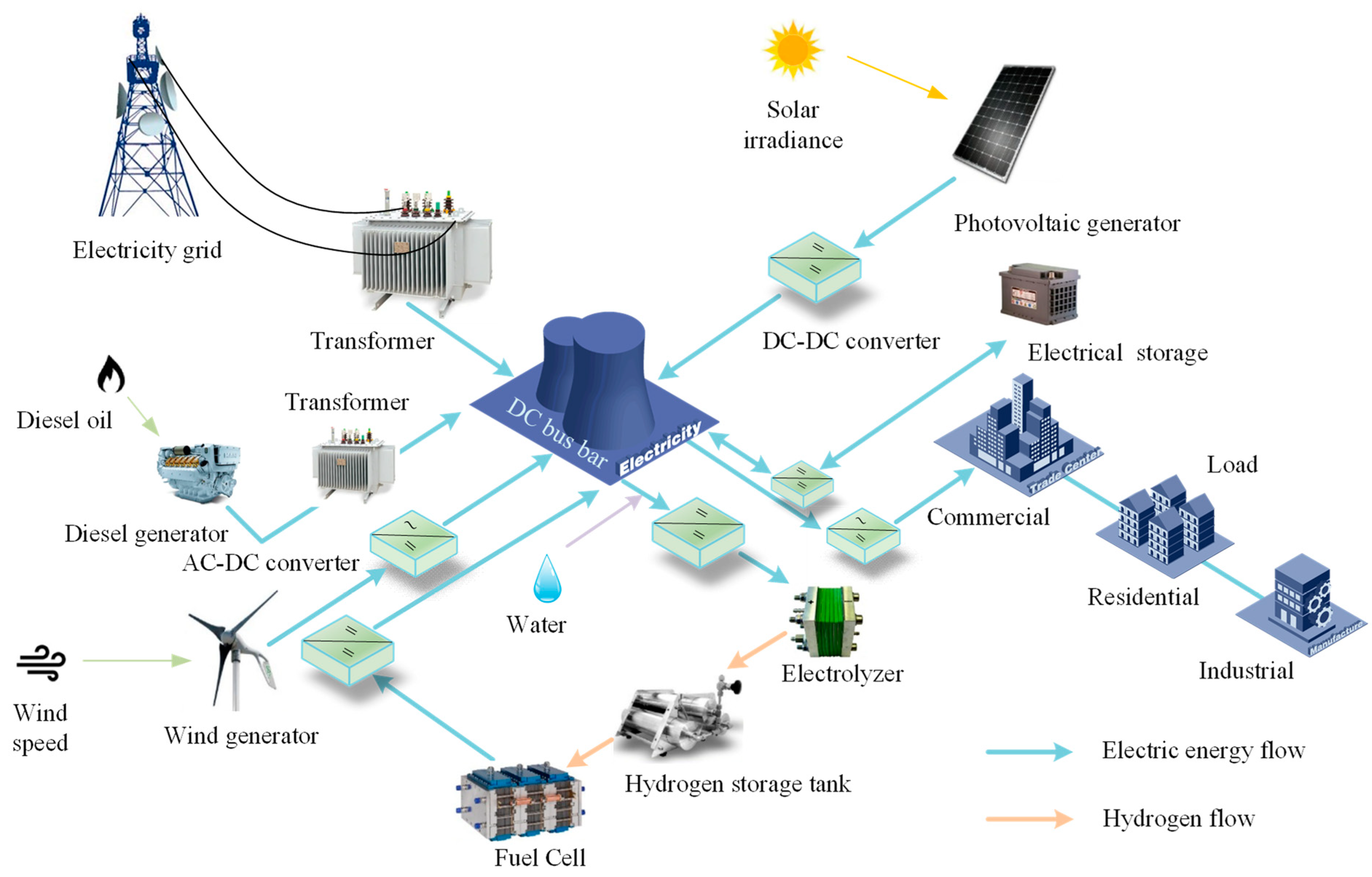
To establish a wind–solar–diesel grid-connected microgrid system with seasonal hydrogen energy storage, a distributed energy system is selected in this paper. The system includes photovoltaic arrays, wind turbines, and diesel units. Based on the above, the microgrid is equipped with diesel engines and has grid connection characteristics. With increasing load demand, it can flexibly purchase power from the main power grid and use diesel generators to generate electricity. Therefore, the model can flexibly deal with deviations caused by changes in the amortization period. The specific structure is shown in Figure 1. The relevant parameters of the microgrid model and their meanings are shown in Table 1.

Figure 1.
Microgrid structure.

Table 1.
Relevant Parameters of Microgrid and Their Meanings.
2.1. Hybrid Energy Storage System Model
In a hybrid energy storage system based on a combination of electric energy storage and seasonal hydrogen energy storage, electric energy storage is used for suppressing fluctuations caused by sudden changes in the microgrid load demand. In contrast, seasonal hydrogen energy storage is used for establishing large-scale, long-term electric energy storage and transfer technology. The hybrid energy storage system proposed in this paper can flexibly respond to sudden microgrid changes and long-term electricity consumption behavior.
2.1.1. Electric Energy Storage Model
In this paper, a lithium-iron-phosphate battery is selected with a short response time and high cycle efficiency for electric energy storage.
On a daily-time scale, the electric energy storage system is charged to store surplus power during periods when wind and solar power generation are high, and the stored power is released when there is little to no PV or wind power generation, to ensure normal power supply to the load.
The relationship between the electric energy storage capacity and the charging and discharging power is as follows:
2.1.2. Seasonal Hydrogen Energy Storage Model
The hydrogen energy storage system consists of the electrolyzer, hydrogen storage tank, and fuel cell. To improve the flexibility of the model, the proton exchange membrane electrolyzer and proton exchange membrane fuel cell, with excellent dynamic performance and high specific power, are selected [26]. The mathematical models for each component of the system are as follows:
(1) The electrolyzer is energized to electrolyze water for hydrogen gas production, completing the electricity-to-hydrogen conversion process. The output power is denoted as follows:
(2) The hydrogen in the storage tank comes from the electrolytic water reaction in the electrolyzer, and is output to the fuel cell as a power supply. Ignoring hydrogen self-loss, the storage capacity and quality of the storage tank are denoted as follows:
(3) The fuel cell converts hydrogen chemical energy into electrical energy, completing the hydrogen to electricity conversion process. The output power is expressed as follows:
2.2. Wind-Solar Station Model
The wind–solar station consists of the photovoltaic array, the wind turbine, and the diesel engine. The specific model is as follows.
2.2.1. Photovoltaic Array Model
The actual output power of the photovoltaic array is mainly influenced by the solar light intensity and ambient temperature, which can be expressed as follows:
2.2.2. Wind Turbine Model
The output power of the wind turbine is related to the wind speed, and it can be expressed as follows:
2.2.3. Diesel Engine Model
The efficiency of a diesel engine is closely related to its operation mode, and the relationship between fuel consumption and power can be expressed as follows:
3. Multi-Objective Capacity Optimization Configuration of Microgrids with Seasonal Hydrogen Storage
The optimal allocation decision variables in this paper are CPV, CWT, CDG, EES, PES, PEL, EHT, and PFC, which describe the capacity allocation related to microgrid economics and environmental friendliness. Two objective functions of the microgrid are considered: the lowest integrated cost and the lowest carbon emissions.
3.1. Comprehensive Cost of the Microgrid
The comprehensive cost of the microgrid includes the initial equipment investment cost, the replacement costs, the operation and maintenance costs, and the purchase costs of the main grid power. The cost can be expressed as in Equation (8).
The specific expressions in Equation (8) are as follows:
where kCRF represents the fund recovery factor. The expression is kCRF = r(1 + r)N/(1 + r)N − 1, where r is the discount rate. The i-related parameters are shown in Table 2.
Table 2.
Decision Variable Parameter Cross Reference.
3.2. Carbon Emissions of the Microgrid
There are two main sources of carbon emissions from the microgrid: the carbon emissions from purchasing electricity from the main grid Ee, and the carbon emissions from diesel generator operation EDG. Thus, the carbon emissions can be expressed as follows:
3.3. Restraint Conditions
3.3.1. Power Balance Constraint
To ensure the system power balance during grid operation, the following constraints are imposed:
3.3.2. Electrical Energy Storage Constraints
Electrical energy storage is used to solve the daily supply-demand imbalance with the following relevant constraints:
(1) The electrical energy storage charge state constraint.
(2) The constraints of charging and discharging power from the electrical storage system. The system cannot charge and discharge at the same time to prolong the service life.
where N1 = min {Zp, Mμ1}, and N2 = min {Zp, M(1-μ1)}. M is a large positive number. μ1 is a 0–1 variable. The electrical energy storage is charging when μ1 = 1, and discharging when μ1 = 0.
(3) The electrical energy storage operating cycle constraint; the electrical energy remaining in the last period of the day is equal to the initial electrical energy.
where y∈{1,2,…365}.
3.3.3. Seasonal Hydrogen Energy Storage Constraints
Unlike electrical energy storage systems, seasonal hydrogen storage systems are responsible for the long-term coordination of power supply and demand with the following relevant constraints:
(1) Hydrogen storage tank status constraints.
(2) Electrolyzer and fuel cell operating power and behavioral constraints. The system cannot operate the electrolyzer and fuel cell at the same time.
where O1 = min {ZEL,Mμ2}, and O2 = min {ZFC,M(1 − μ2)}. μ2 is a 0–1 variable. The electrolyzer is operating when μ2 = 1, and the fuel cell is operating when μ2 = 0.
(3) Hydrogen storage operating cycle constraint. The amount of hydrogen remaining in the storage tank in the last period of the year is equal to the initial hydrogen storage capacity.
Where Tn∈{0,1,…, TN}.
3.3.4. Investment Constraints
Due to the limitations of the construction site scope, the capacity of each microgrid equipment configuration must be within a reasonable range. The relevant constraint can be expressed as follows:
3.3.5. The Operational Constraints
When the system is running, each device output can not exceed its maximum power. Therefore, the relevant constraint can be expressed as follows:
The values of the important parameters used for the construction of the microgrid system are shown in Table 3.
Table 3.
Values of Important Parameters.
3.4. Evaluation Index of the Microgrid System
The renewable energy abandonment rate is an important measure of the degree to which grid-connected microgrids utilize their generated power and their self-balancing capabilities. The rate can be described as follows:
where the smaller the rate is, the higher the renewable energy utilization.
The objective scalar function solved in this paper is expressed as follows:
where x∈X, x is the vector of the decision variables, and X is the feasible domain of x. The augmented ε- constraint method is used to solve the model.
3.5. Operation Control Strategy of Microgrid
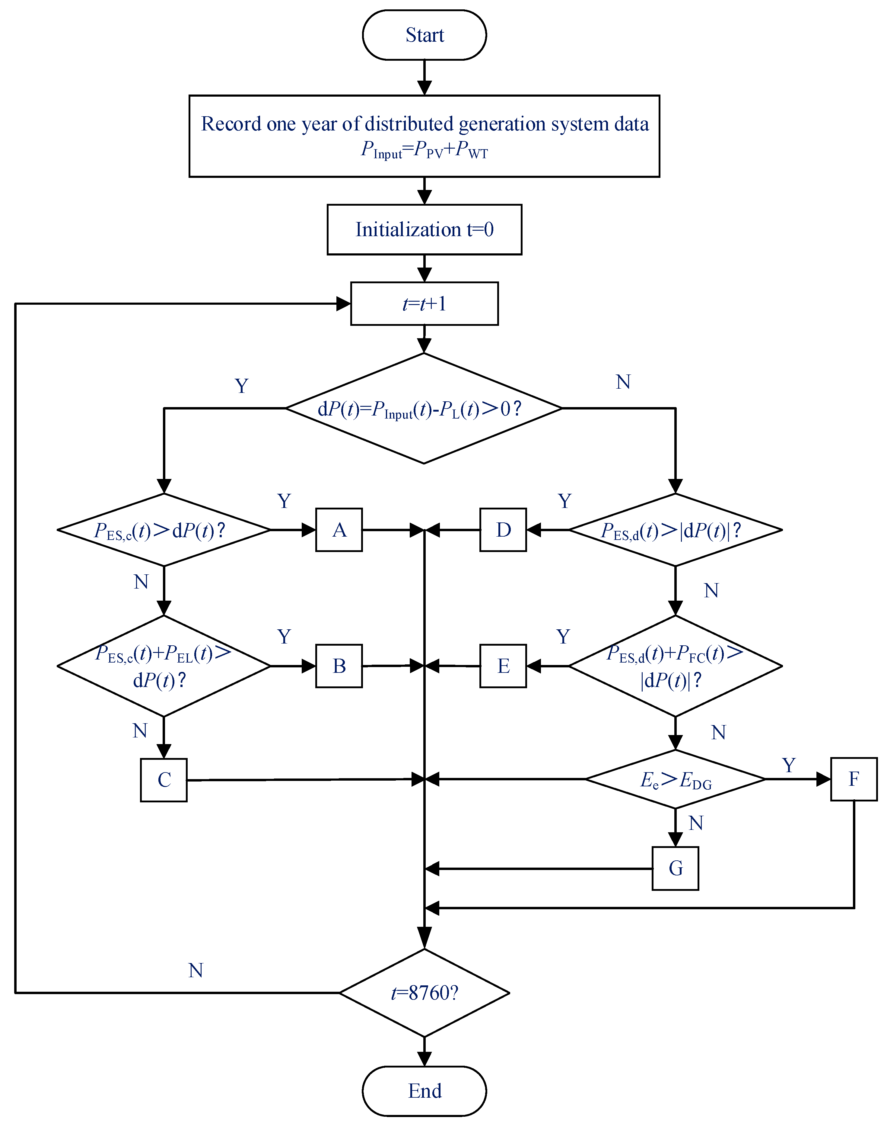
The operation control strategy of the microgrid determines the power output sequence of each resource in the microgrid, which directly affects the operation of the electric energy storage and hydrogen storage system, and thus, the merits of the configuration scheme. The operation strategy flow of the proposed microgrid system is shown in Figure 2.
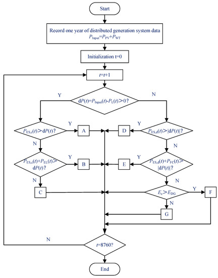
Figure 2.
Operation management strategy flow chart.
A: After the load demand power is satisfied, all the remaining power of the distributed power generation system is used to charge the electric energy storage.
B: After the load demand power is satisfied, part of the remaining power of the distributed power generation system is used to charge the electric energy storage, and the other part is converted to hydrogen and stored through the electrolyzer.
C: After the distributed power generation system meets the load demand power, it charges the battery until saturation, and then provides sufficient energy for the electrolyzer. The remaining renewable energy abandonment; energy abandonment rate is calculated as RateWT; RatePV.
D: The system shortage power is all provided by the electric energy storage.
E: The electric energy storage is fully discharged to provide part of the shortage power for the system, and the remaining part is provided by the fuel cell power generation.
F: Full discharge of the electric energy storage and full power generation of the fuel cell provide part of the power for the system, and the subsequent shortage of power is provided by the diesel generator.
G: The battery is fully discharged and the fuel cell is fully generated to supplement part of the system power, and the subsequent power shortage is provided by the main grid.
4. Capacity Optimization Allocation Model of Microgrid System Based on the Augmented ε- Constraint Method
Based on the model in this paper, which contains 0–1 integer variables that characterize the charging and discharging states of electrical and hydrogen energy storage, the operating characteristics of the equipment are determined. It is proposed to use the ε- constraint method and to employ AUGMECON in order to solve the MILP [31,32].
4.1. The Augmented ε- Constraint Method
The ε- constraint method is a solution method that retains only a single objective function, and transforms the other objective functions into constraints. However, the solution process requires approximating the extreme value points by sorting, expanding, and compressing, which is a tedious step that makes it difficult to find the maximum possible value of the minimizing objective function.
This issue can be resolved by proposing the augmentation-constraint method to transform the inequality constraint corresponding to the nonprincipal objective, into an equation constraint by introducing relaxation variables. Other objective functions are transformed into equation constraints to participate in the optimization. A relaxation variable penalty function is also introduced to overcome the influence of the objective function nonconvexity on the solution quality, and to ensure solution nondominance. Thus, the expression of the objective function is as follows:
Equation (22) is bounded by Equation (23):
where ε is a sufficiently small constant between 10−3 and 10−6, sn is the slack variable, and ri is the width of the range of values of the i-th objective function. The formula is the difference between the maximum and minimum values of the column, expressed as ri = Fimax − Fimin. ei is the step adjustment value, and the formula is calculated as follows:
where i∈{2,…,n}, k∈{1,…,g}. By iterating k from 0 to g repeatedly, the value of ei is adjusted continuously, and the model is iteratively calculated after each adjustment. Then, a set of Pareto-optimal solutions required for the objective function can be obtained.
4.2. Multi-Objective Function Solution Based on the Augmented ε- Constraint Method
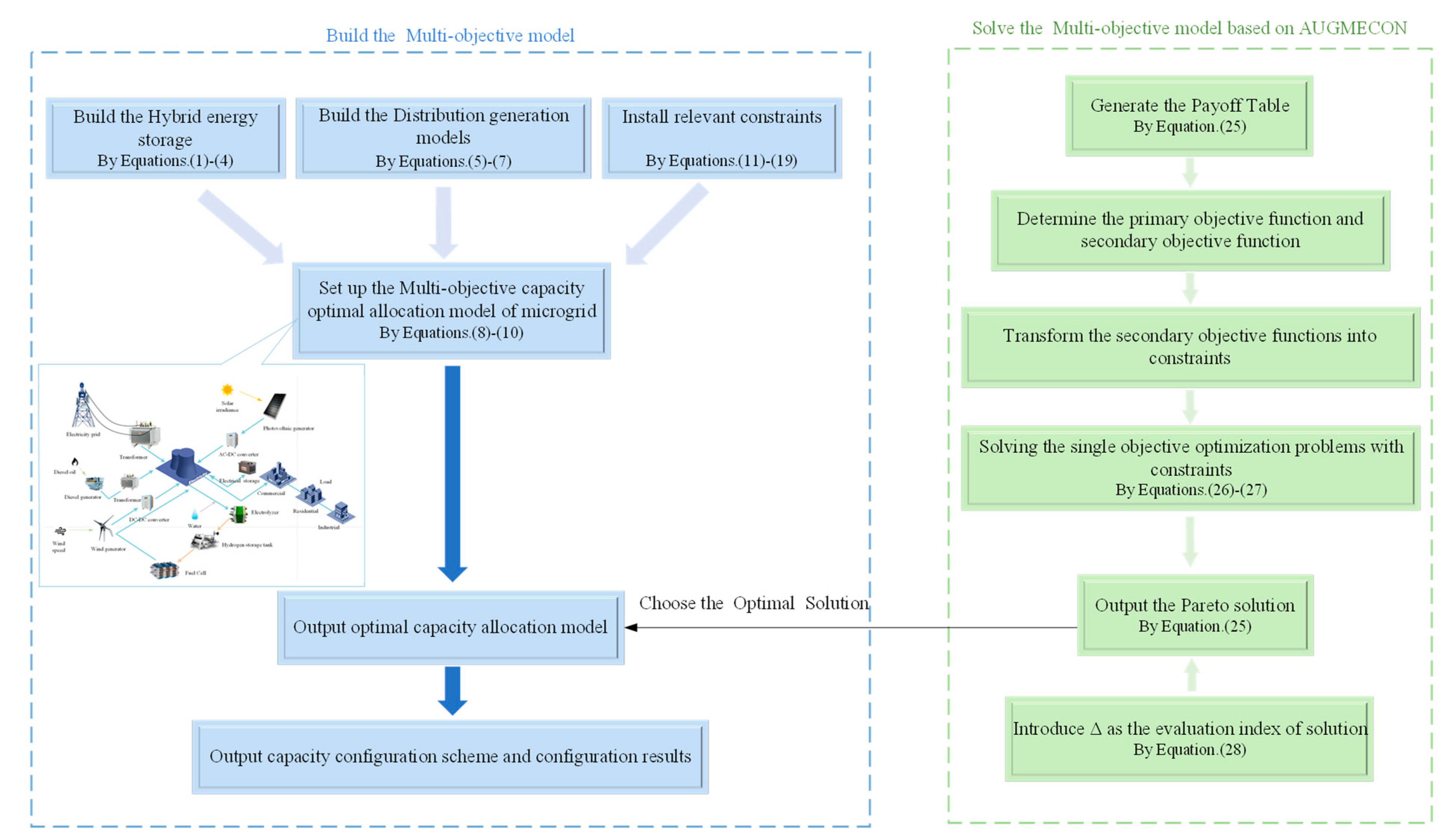
This section specifies the multi-objective function that is solved based on the AUGMECON method, and the specific process of the capacity optimization allocation model of the microgrid system, as shown in Figure 3. The augmented ε- constraint method can accurately find the range of values of the objective function. Thus, the effectiveness of the Pareto front is significantly improved. The solution process is as follows:
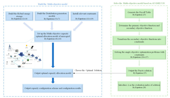
Figure 3.
Flow chart of capacity optimal allocation of microgrid system based on AUGMECON.
(1) Generating the payoff table
The payoff table is used to confirm the upper and lower bounds of each objective Pareto front function. The specific payment table is shown in Table 4.
Table 4.
Bi-Objective Function Payment Table.
Where:
In the table, F1(x) is used as the unique objective function for calculation. Then, the obtained decision variables are brought into F1(x) and F2(x) to obtain the corresponding objective function values Z11 and Z12. Z11 and Z12 correspond to the minimum and maximum values of the objective F1 in the first column of the payoff table, respectively.
Similarly, the above operations are performed on the second objective function F2(x) to obtain Z21 and Z22, which correspond to the minimum and maximum values of objective F2 in the second column of the payment table, respectively.
(2) Solving the new optimization problem constraints
F1(x) is taken as the primary objective function, and the secondary objective function F2(x) is treated as the constraint. The range of values of F2(x) are divided into g segments. The new single-objective optimization problem is solved as follows:
where the constraint of Equation (26) is F2 + s2 = e2. In the formula, r2 = Z21 − Z22. e2 is calculated by Equation (27).
In this paper, g = 40. By continuously adjusting the value of e2 and iterating the above equation, the desired Pareto front solutions are calculated.
(3) Evaluation indicators
In this paper, Δ is introduced as the evaluation index of the Pareto distribution characteristics.
A smaller Δ represents a more uniform Pareto front solution distribution with better characteristics.
(4) Filtering the optimal compromise solution
After finding the Pareto front through the above steps, the optimal compromise solution is derived by evaluating all noninferior solutions with the entropy–TOPSIS method [33]. Specifically, the entropy weighting method is used to determine the weights of the two objective functions. The TOPSIS method sorts and selects the solution that is closest to the positive ideal solution in terms of Euclidean distance [Z11, Z22], and farthest from the negative ideal solution in terms of Euclidean distance [Z21, Z12], as the optimal compromise solution under the given weights.
4.3. Specific Process of the Capacity Optimization Allocation Model of Microgrid System Based on the AUGMECON Method
Step 1: Select each microgrid-distributed energy source and build a distributed energy system model.
Step 2: Establish a composite energy storage system model that involves a coupling between electric energy storage and seasonal hydrogen storage systems.
Step 3: Construct a microgrid capacity optimization allocation model that prioritizes the economic and environmental benefits of the microgrid system.
Step 4: By considering the operating conditions and characteristics of each device, set the relevant constraints and evaluation indexes of the microgrid system.
Step 5: Solve the multi-objective optimization model with constraints by using the AUGMECON method, and output the Pareto front solution set.
Step 6: Select the optimal compromise solution in the solution set with the entropy–TOPSIS method.
Step 7: Output the optimal compromise solution to construct the optimal capacity allocation model.
Step 8: Output the system capacity configuration scheme and the configuration results.
5. Example Analysis
In Section 5, experimental validation and analysis are performed for the models and algorithms proposed in this paper. In Section 5.1, first, the environment of the simulation experiment and the data and sources related to the model input are explained, and second, four different microgrid scenarios are built. In Section 5.2, the effectiveness of the algorithm proposed in this paper is verified. In Section 5.3, the algorithm of this paper is applied to the above four microgrid scenarios to verify the effectiveness of the model. Finally, in Section 5.4, the operation of scenario 3 and scenario 4, on typical days of the seasons in a year, is focused on in three examples, and the sensitivity analysis of the key parameters affecting the objective function is carried out to further prove the rationality and practicality of the proposed method in this paper.
5.1. Example Scenarios and Related Parameter Settings
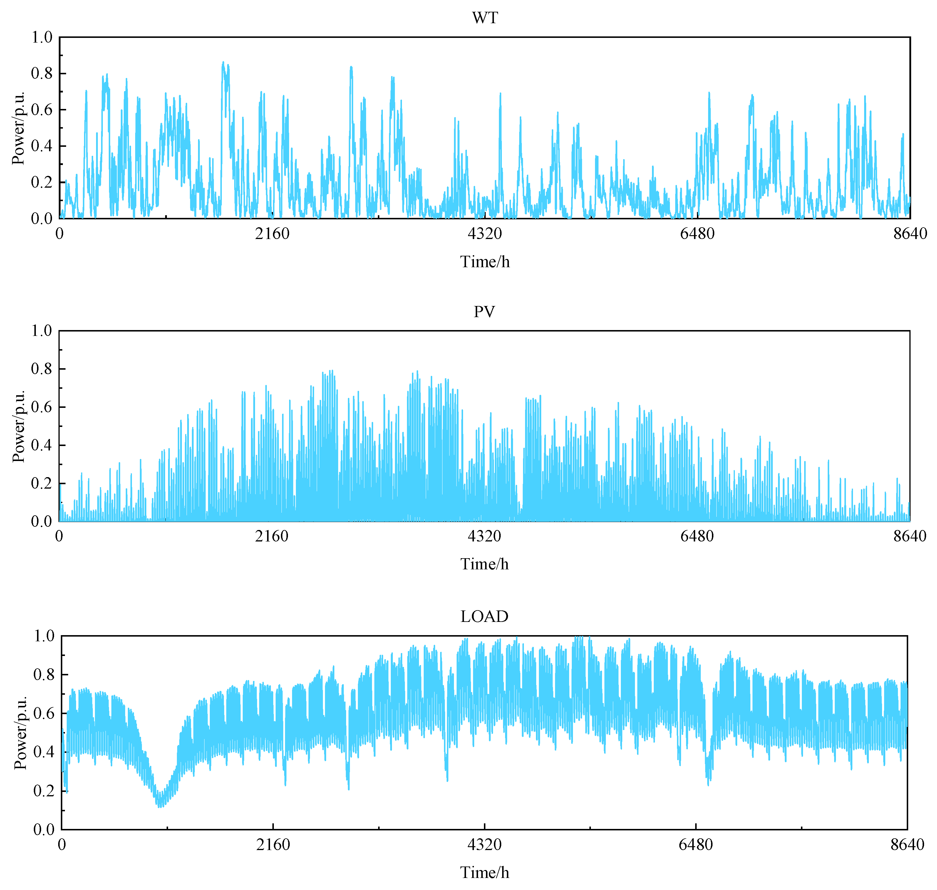
The solver used in this paper is Gurobi, and the example uses the modeling language Yalmip to quickly solve the problem in MATLAB. The real-world data of a grid-connected microgrid in an integrated wind power plant in Belgium are used as the input data. The actual annual load data for the microgrid at an hourly resolution, and the standardized values for wind and light power generation, are shown in Figure 4 [34]. Table 5 and Table 6 give the unit price of the power purchased from the main grid and the investment parameters of each piece of microgrid equipment, respectively [35,36].
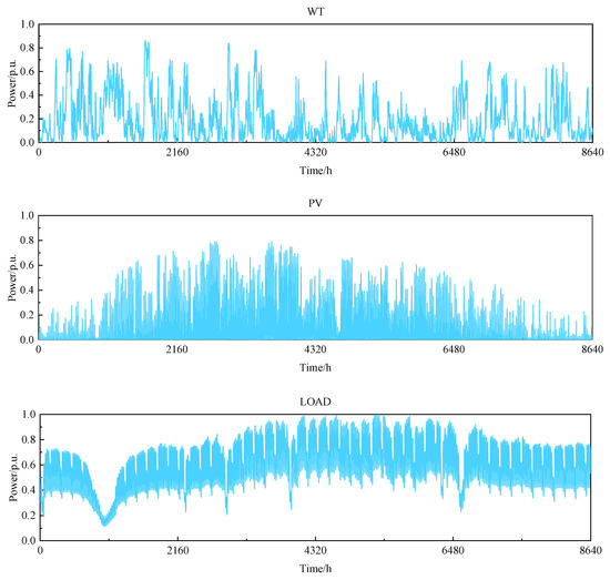
Figure 4.
Annual wind power photovoltaic and load power data.
Table 5.
TOU Power Price.
Table 6.
Investment Parameters of Microgrid Equipment.
To analyze the effectiveness of configuring seasonal hydrogen energy storage, four scenarios are chosen as follows:
Scenario 1: Multi-objective capacity optimization configuration of a microgrid with electrical energy storage and without seasonal hydrogen storage systems.
Scenario 2: Multi-objective capacity optimization configuration of a microgrid with seasonal hydrogen storage and without electrical storage systems.
Scenario 3: Multi-objective capacity optimization configuration of a microgrid with both electrical energy storage and hydrogen energy storage systems for short-cycle energy storage.
Scenario 4: Multi-objective capacity optimization configuration of short-cycle electrical energy storage and seasonal hydrogen energy storage for seasonal energy storage.
5.2. Comparative Analysis of the AUGMECON Method and Other Algorithms
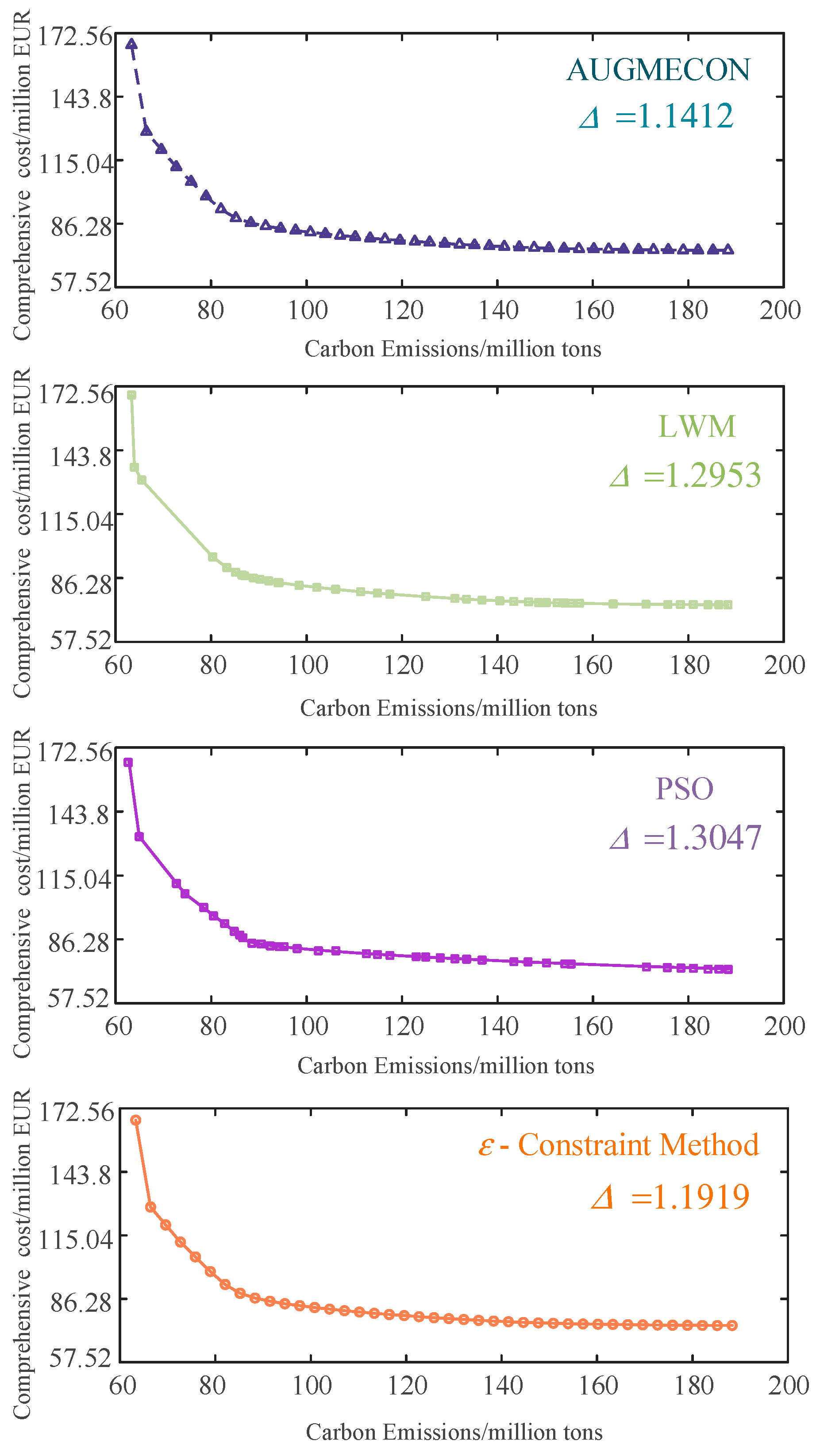
To verify the effectiveness of the AUGMECON method, it and the ε- constraint method, linear weighting method (LWM), and PSO are used to solve the multi-objective microgrid capacity optimization allocation problem to obtain the Pareto front graph.
The degree of concavity of the Pareto curve reflects the superiority of the frontier solution in the curve. Δ is the indicator of the distributivity of the frontier solution; the smaller it is, the more uniform the distribution of the frontier solution and the better the distribution characteristics.
As shown in Figure 5 and Table 7, the frontier solutions of the LWM and the PSO are not uniformly distributed and have poor distributional properties. The above two algorithms are 8.1% and 8.6% worse than the ε- constraint method in terms of distributivity index, respectively. However, these two algorithms are 9.8% and 10.1% faster than the ε- constraint method in terms of operation speed, respectively. Through data analysis, the ε- constraint method, linear weighting method, and particle swarm algorithm each have advantages in terms of frontier solutions and computational power.
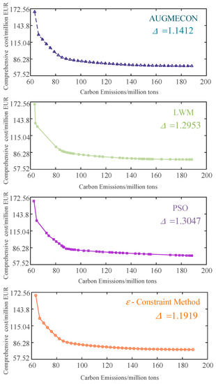
Figure 5.
Pareto optimization results by different algorithms.
Table 7.
Comparison of Multi-objective Algorithms.
The frontiers of the AUGMECON method and ε- constraint method are close, the degree of concavity of these two algorithms is more pronounced and better, overall, than the LWM and the PSO. Additionally, as shown alongside the algorithm computing time analysis in Table 7, the AUGMECON method is 28.3%, 20.1%, and 20.2% faster than the ε- constraint method, LWM, and PSO, respectively, in terms of solution speed. The AUGMECON method has a lower Δ value, a more uniform distribution of solution sets, and a better diversity of solution sets. Therefore, a better Pareto solution sets can be obtained by the AUGMECON method.
5.3. Analysis and Comparison of Different Energy Storage Solutions
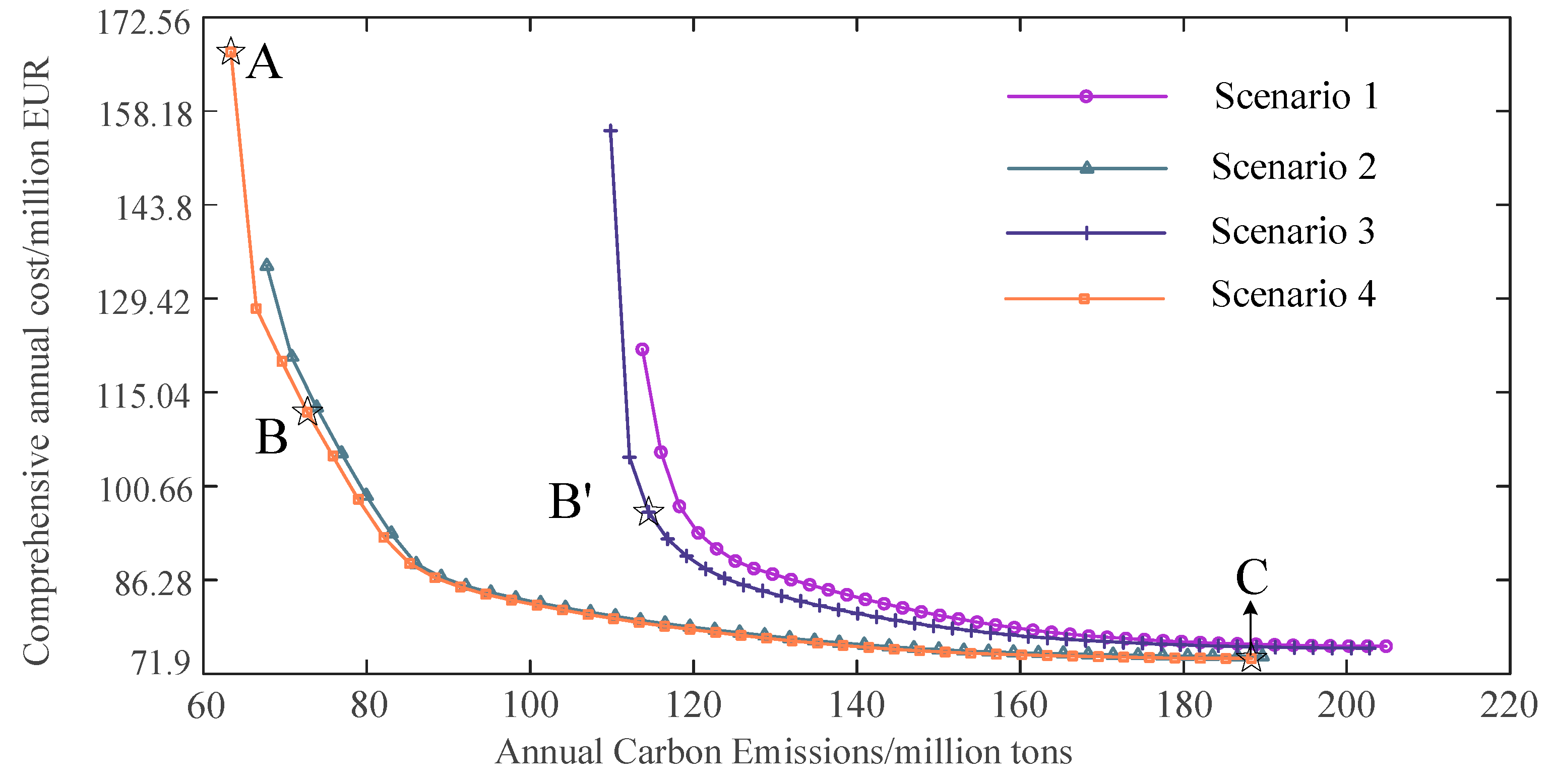
After the superiority of AUGMECON has been demonstrated in Section 5.3, this section will experimentally verify and analyze the effectiveness of the model proposed in this paper. Based on the four different microgrid models built in Section 5, AUGMECON is applied to each of the four scenarios in this section. The Pareto front for the multi-objective problems of Scenarios 1–4 is obtained by the AUGMECON method, as follows.
In the Pareto diagram, the closer the curve, as a whole, is to the origin, then the Pareto solution set on this curve is better. As shown in Figure 6, Scenarios 1–3 are all further away from the origin than Scenario 4; thus, Scenarios 1–3 are all dominated by the Pareto front of Scenario 4.
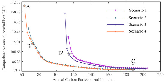
Figure 6.
Pareto optimization results in different scenarios.
First, Scenario 1 and 2 are compared. The analysis showed that the microgrid configured according to Scenario 2 had less carbon emissions while spending the same combined annual cost. This proves that seasonal hydrogen storage has a significant energy saving and emission reduction effect. Then, Scenario 3 and 4 are compared, and the results indicate that Scenario 4 requires a lower comprehensive annual cost charge for the same carbon emission conditions. This proves that it is more economical and practical to use hydrogen storage as seasonal energy storage for long-time cycle dispatch operation compared to the short-time.
5.4. Capacity Optimization Allocation Results and Analysis
In this section, three examples are used to analyze the capacity configuration scenarios and the configuration results with the incremental-bound method under Scenario 4. In addition, this section features a comparison and analysis of the capacity change and typical daily operation of the energy storage system for Scenarios B and B’, to further validate the model proposed in this paper.
5.4.1. Example 1
The work in Example 1 consists of selecting the optimal compromise solution among the frontier solutions calculated using AUGMECON under Scenario 4. Configuration schemes A, B, and C, shown in Figure 6, correspond to the optimal solution, with F2 as a single objective; the optimal double objective, the solution derived from the entropy–TOPSIS method; and the optimal solution, with F1 as a single objective, respectively. Table 8 and Table 9 give the capacity configuration options and results for each device in the microgrid at points A, B, and C, under Scenario 4. B’ corresponds to the bi-objective optimal compromise solution of Scenario 3, derived from the entropy–TOPSIS method.
Table 8.
Capacity Configuration Scheme for Each Equipment of Microgrid.
Table 9.
Capacity Configuration Results of Microgrid Equipment.
First, Option C employs low-capacity PV, WT, electric storage, and hydrogen storage with high-capacity diesel to minimize the combined annual cost of the microgrid. Although the cost is reduced, the configuration yields high carbon emissions and poor environmental friendliness. Second, to reduce carbon emissions, Option A uses large-capacity electrical and hydrogen energy storage to consume as much renewable power as possible. However, the total configuration cost is too high to be of practical use. Finally, Option B appropriately increases the capacities of both types of energy storage, significantly reduces carbon emissions without sacrificing excessive economic benefits, and achieves an optimal compromise between the annual combined cost and annual carbon emissions. Therefore, compared with Option A and Option C, Option B is able to achieve a higher level of satisfaction with both economic and environmental objectives, and has good engineering practicality.
5.4.2. Example 2
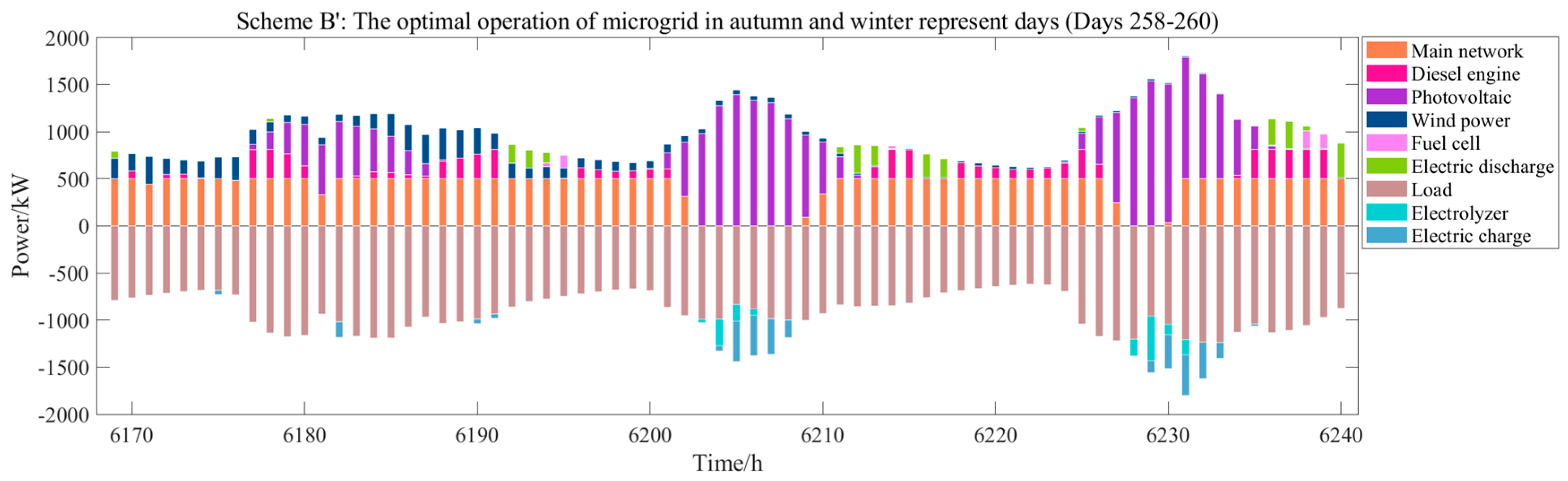
To further verify the validity of the proposed model, and to also analyze the configuration scheme and operation strategy of electrical and hydrogen energy storage, a comparative analysis is conducted using Options B’ and B.
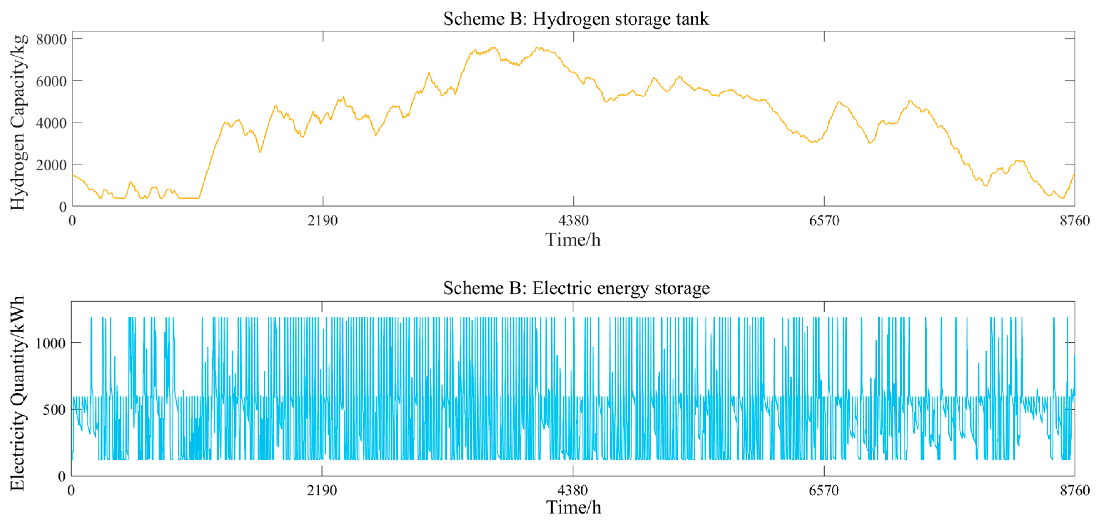
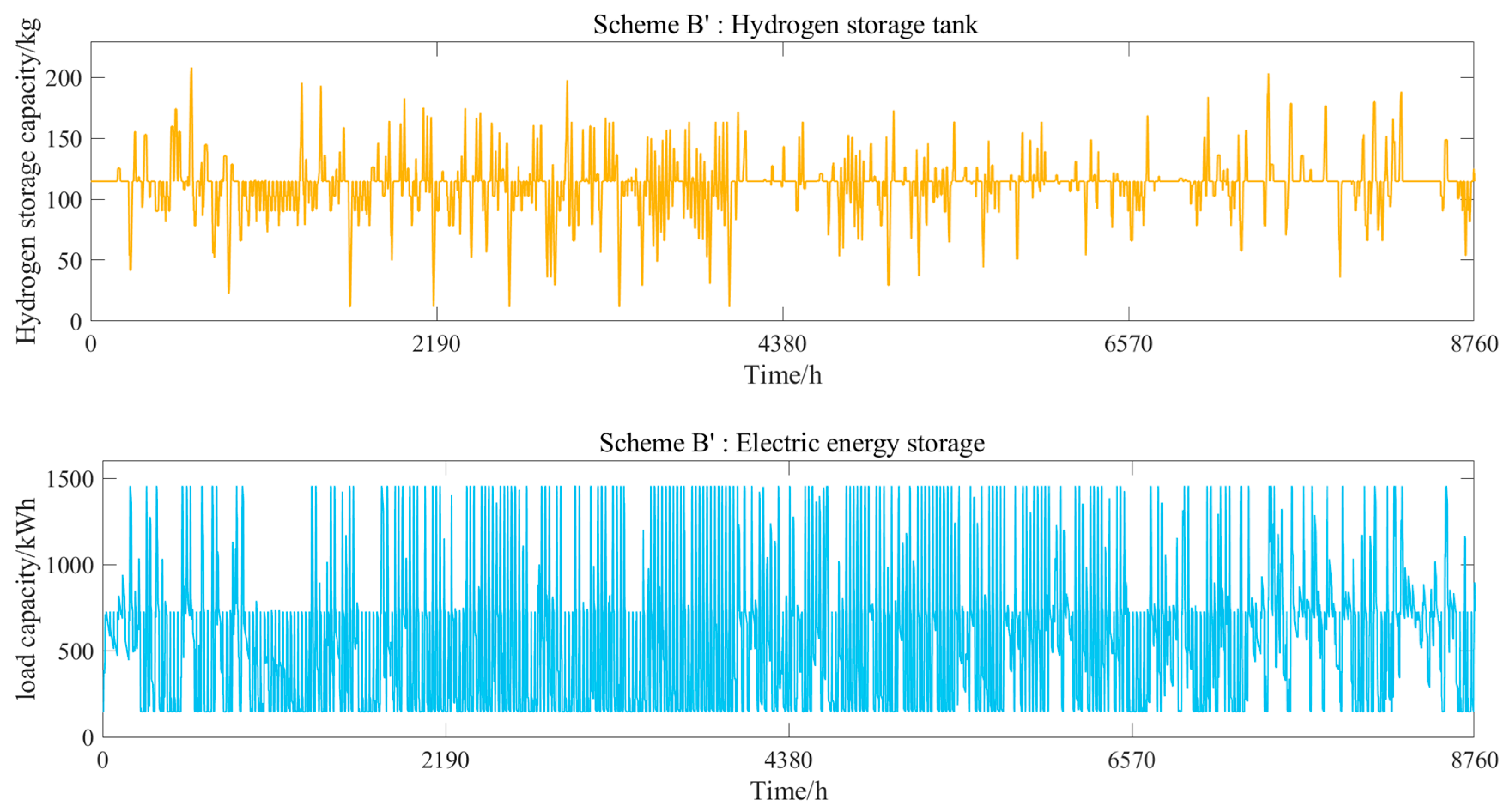
Figure 7 shows the variation in the storage capacity of the two scenarios, corresponding to the electrical energy storage and hydrogen storage tanks. Figure 8 shows the operation of the two scenarios on a typical day in spring and summer. Figure 9 shows the operation of both scenarios for a typical day in autumn and winter.
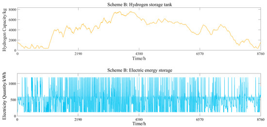
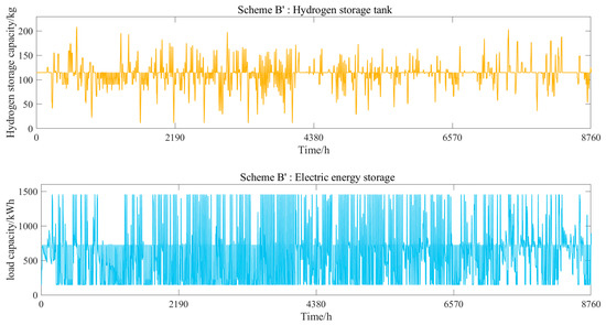
Figure 7.
Annual reserve change of electric energy storage and hydrogen storage tanks in two schemes.

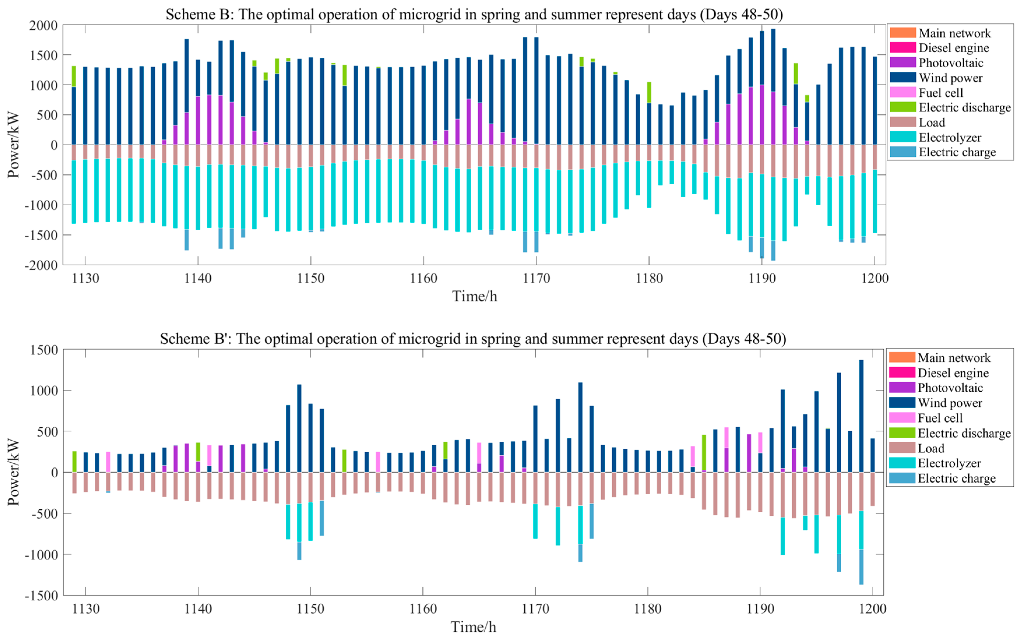
Figure 8.
The optimal operation of the microgrid with two schemes in spring and summer represents day (Days 48−50).
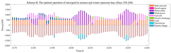
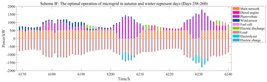
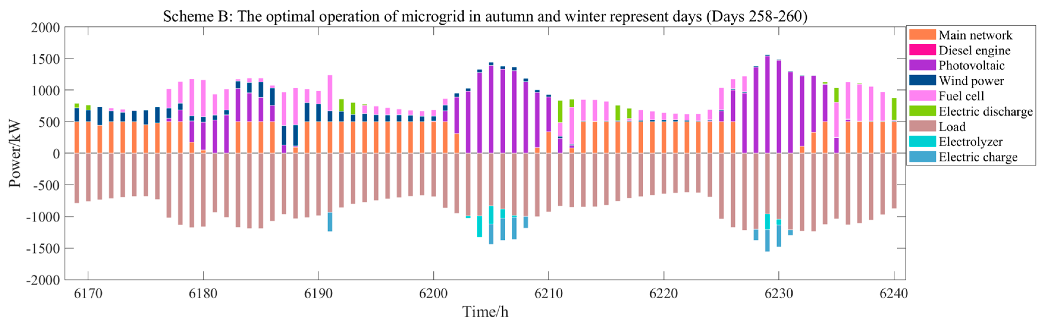
Figure 9.
The optimal operation of the microgrid with two schemes in autumn and winter represents day (Days 258−260).
By analyzing Figure 7, Figure 8 and Figure 9, when configuration scheme B’ is employed, and because the hydrogen storage system operates daily, the microgrid system struggles to consume the renewable energy generation in the spring and summer, when the scenery resources are abundant. This will lead to the large-scale abandonment of the scenery resources; therefore, it needs to be equipped with a higher capacity distributed generation system, which greatly increases the construction investment cost. Meanwhile, in the autumn and winter, when natural resources are scarce, in order to respond to load demand, the power purchase of microgrids is greatly increased, which increases the system operation cost and carbon emissions. However, the role played by energy storage here is very small and does not correspond to the expected function of energy storage to regulate peaks and fill valleys from a long cycle. Therefore, this configuration scheme does not bring out the maximum advantages of energy storage.
When configuration scheme B is employed, the hydrogen storage system operates on an annual basis, and the microgrid system relies on scenery generation for autonomous operation when scenery resources are abundant. The capacity of the distributed generation system required is greatly reduced compared to configuration scheme B’, and the corresponding investment cost is significantly reduced. The excess scenic power generation is used for electrolysis to produce hydrogen, which can be transferred to be released in autumn and winter, and thus, reducing the microgrid power purchase and achieving economical and environmentally friendly operation of the system.
The analysis of the operation of configuration scheme B’ and configuration scheme B further strongly proves the effectiveness of the model proposed in this paper.
5.4.3. Example 3
Studies around the world have used the method of varying the key system parameters and then calculating the corresponding optimal solution to analyze the effect of input parameter changes on the output results [37]. In this section, a sensitivity analysis is carried out to evaluate the impacts of key parameters on the objective function.
With the development of production capacity, the system power load demand increases, and the corresponding distributed power, output power, energy storage power, and capacity will change, affecting the system acquisition cost, the operation and maintenance cost, and the total cycle cost of the system. With the iterative improvement of the hydrogen energy industry chain and technological progress, the cost of hydrogen production and storage will show a decreasing trend in the immediate and long-term development process, and the high investment cost of the hydrogen storage system has a direct impact on the optimal configuration of the microgrid. Therefore, a sensitivity analysis of hydrogen production, storage costs, and load demand will be carried out with the arithmetic examples below.
(1) Example 1: The climatic input conditions and the cost of each part of the system remain unchanged, and the residential electric load increases by 10%.
(2) Example 2: The climatic input conditions and residential load demand of the system remain unchanged, and the acquisition cost of fuel cells, electrolytic cells, and hydrogen storage tanks in the system decreases by 10%.
The configuration results in Table 10 show that: as the demand for electricity load expands, the total capacity of the power supply required by the system will increase. Under the power curves of the PV, wind turbine, and load in this study, it is shown that the capacity of PV slightly decreases and the capacity of the wind turbine greatly increases, while the capacities of the electrolyzer and fuel cell increase. Therefore, it is necessary to prepare for expansion in the early stages of construction. As the cost of the hydrogen energy system decreases, the PV capacity greatly decreases and the hydrogen energy equipment capacity increases. The low-carbon emission reduction effect is significant, and the development prospects of the hydrogen energy system are highly optimistic as the technology evolves.
Table 10.
Results of Configuration.
6. Conclusions
To increase the economic benefits and environmental friendliness of microgrids, this paper proposes a capacity optimization allocation method for a wind–solar–diesel grid-connected microgrid system with hybrid energy storage, based on the AUGMECON method. By comparing different energy storage configuration models and optimization algorithms, the effectiveness and superiority of the proposed models and algorithms in this paper are proven. The specific conclusions are as follows:
(1) The augmented ε- constraint method can effectively solve the double objective optimization model in this paper. The AUGMECON method is found to obtain a Pareto front solution set with greater validity, better distribution characteristics, and higher computational speed than the solution sets found with the ε- constraint method and the other three algorithms.
(2) The constructed hybrid energy storage model that couples battery and seasonal hydrogen storage systems greatly enhances local consumption of renewable energy. The proposed model greatly improves the economic benefits and environmental friendliness of system operation, compared to those in existing studies on short-cycle energy storage.
In summary, the microgrid capacity optimization allocation method proposed in this paper has good effectiveness and can quickly obtain the economic and low-carbon target configuration of a microgrid with good results. In future research, we will continue to combine device refinement models to determine the optimal configuration of microgrid capacity.
Author Contributions
Writing—original draft, X.Z.; Writing—review & editing, X.S. and Y.W. All authors have read and agreed to the published version of the manuscript.
Funding
This research was funded by [National Natural Science Foundation of China] grant number [61561020] and the APC was funded by [National Natural Science Foundation of China].
Data Availability Statement
Publicly available datasets were analyzed in this study. These data can be found here: https://www.elia.be/, accessed on 1 January 2020.
Conflicts of Interest
The authors declare no conflict of interest.
Appendix A

Figure A1.
Schematic Diagram of the Function of Seasonal Energy Storage.
Figure A1.
Schematic Diagram of the Function of Seasonal Energy Storage.
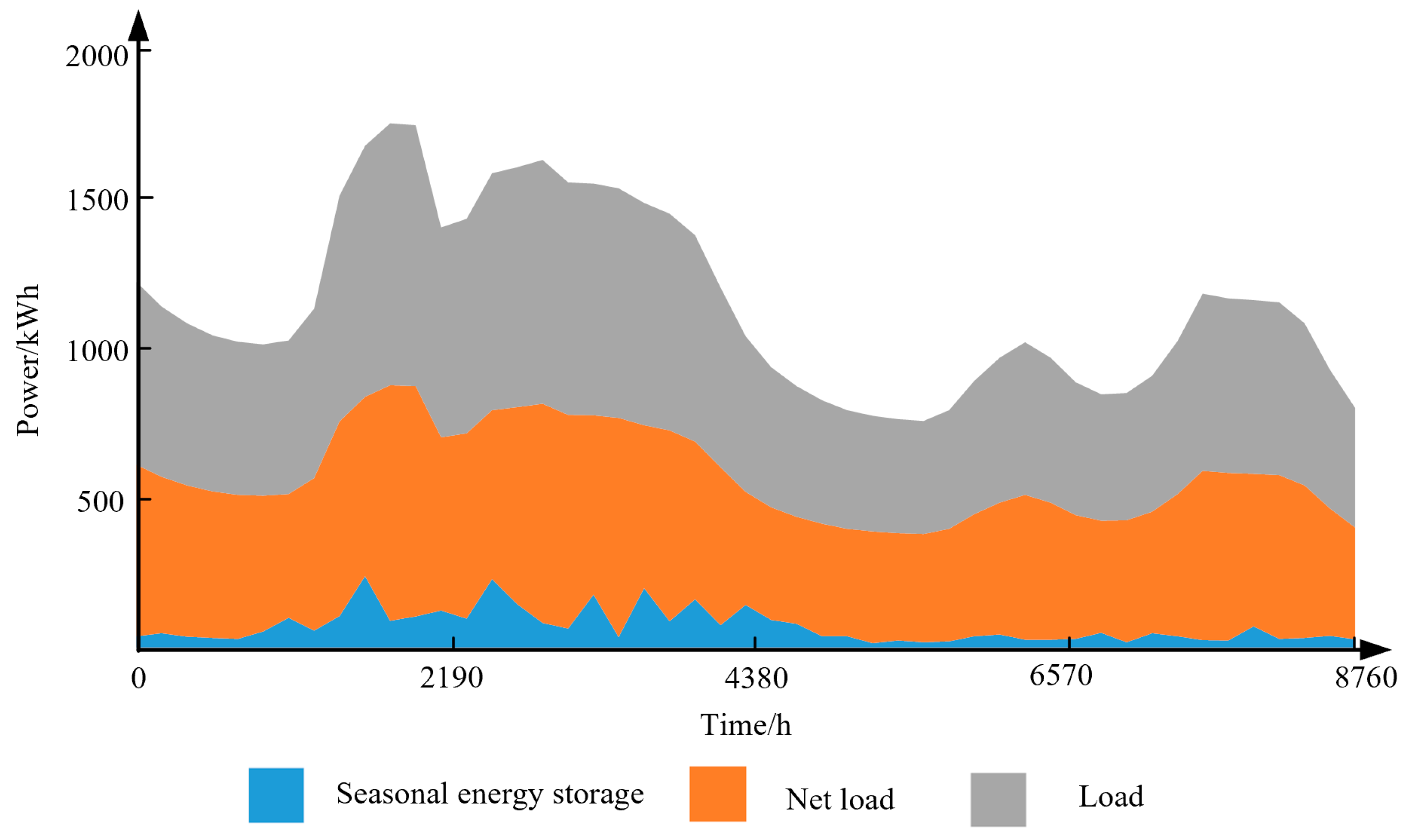
Table A1.
Classification of Energy Storage System.
Table A1.
Classification of Energy Storage System.
| Types of Energy Storage | Type of Stored Energy | Typical Representatives |
|---|---|---|
| Mechanical energy storage | The potential energy of water | Pumped storage |
| Kinetic energy of gas pressure | Compressed air storage | |
| Kinetic energy of the rotating mass | Flywheel Energy Storage | |
| Electric energy storage | Electricity in magnetic fields | Superconducting magnetic energy storage |
| Electricity in an electric field | Supercapacitor | |
| Electrochemical Energy Storage | Electrochemical energy in the electrode | Classic Battery Energy Storage |
| Electrochemical energy in electrolyte | Redox battery energy storagehybrid flow battery energy storage | |
| Thermal Energy Storage | Heat energy in particle motion | Sensitive thermal storage device |
| Heat storage by heat absorption reaction | Thermochemical Energy Storage | |
| Chemical Energy Storage | Conversion to gas | Electricity and gas power plants |
| Conversion to fuel | Power fluid system | |
| Converted to chemical products | Electric Power Chemical Plant |
Table A2.
Characteristics of Different Energy Storage Devices.
Table A2.
Characteristics of Different Energy Storage Devices.
| Energy Storage Type | Supercapacitor | Lead-Acid Batteries | Lithium Battery | Hydrogen Energy Storage |
|---|---|---|---|---|
| Energy density Wh/kg | 5–10 | 30–50 | 120–180 | 500 |
| Power density W/kg | 1000–18,000 | 200–500 | 1000 | 1 kW–1 GW |
| Circulation efficiency (%) | >95 | 75–90 | 85–98 | 40–70 |
| Response time (s) | 0.001–0.02 | >0.02 | 0.01–0.02 | 1 s-h |
| Energy release time | 1 ms–1 s | 1 s–10 h | 1 s–10 h | 1 s–24 h |
| Cycle life (times) | >50,000 | 2000–4000 | 2000–10,000 | 20 years |
Energy storage systems can be divided into energy and power types based on their functions. Energy-based energy storage systems have a high energy density and large capacity but also a long discharge time and short cycle life; these systems can be used as a long-term energy storage device. Power-type energy storage systems have a high-power density, fast response speed, and long cycle life, but they cannot handle large-capacity storage and can only be used as a short-term storage device.
References
- Wang, X.; Tang, Z. Optimal capacity allocation of grid connected microgrid considering self balancing of supply and demand and independent operation capacity. Acta Energ. Sol. Sin. 2021, 42, 74–82. [Google Scholar]
- Wang, J.; Li, D.; Zhang, J.; Cai, C.; Gu, L.; Li, H. The Control of Microgrid Energy Storage System Guarantees the Power Quality. J. Harbin Univ. Sci. Technol. 2021, 26, 87–93. [Google Scholar]
- Liu, C.; Zhuo, J.; Zhao, D.; Li, S.; Chen, J.; Wang, J.; Yao, Q. A Review on the Utilization of Energy Storage System for the Flexible and Safe Operation of Renewable Energy Microgrids. Proc. CSEE 2020, 40, 1-18+369. [Google Scholar]
- Jiang, H.; Du, E.; Zhu, G.; Huang, J.; Qian, M.; Zhang, N. Review and Prospect of Seasonal Energy Storage for Power System with High Proportion of Renewable Energy. Autom. Electr. Power Syst. 2020, 44, 194–207. [Google Scholar]
- Weimann, L.; Gabrielli, P.; Boldrini, A.; Jan Kramer, G.; Gazzani, M. Optimal hydrogen production in a wind-dominated zero-emission energy system. Adv. Appl. Energy 2021, 3, 100032. [Google Scholar] [CrossRef]
- Liu, Z.; Qi, G.; Gao, J.; Wang, Z. Research on optimal configuration of hybrid energy storage capacity based on adaptive VMD. Acta Energ. Sol. Sin. 2022, 43, 75–81. [Google Scholar]
- Zhou, L.; Huang, Y.; Guo, K.; Feng, Y. A survey of energy storage technology for micro grid. Power Syst. Prot. Control 2011, 39, 147–152. [Google Scholar]
- Shu, Y.; Chen, G.; He, J.; Zhang, F. Building a New Electric Power System Based on New Energy Sources. Strateg. Study CAE 2021, 23, 61–69. [Google Scholar] [CrossRef]
- Li, Q.; Zhao, S.; Pu, Y.; Chen, W.; Yu, J. Capacity Optimization of Hybrid Energy Storage Microgrid Considering Electricity-Hydrogen Coupling. Trans. China Electrotech. Soc. 2021, 36, 486–495. [Google Scholar]
- Xi, W.; Lv, H.; Tiao, Q. Optimal capacity configuration of wind-photovoltaic-hydrogen microgrid based on non-cooperative game theory. Electr. Power Eng. Technol. 2022, 41, 110–118. [Google Scholar]
- Xiong, Y.; Chen, L.; Zheng, T.; Si, Y.; Mei, S. Optimal configuration of hydrogen energy storage in low-carbon park integrated energy system considering electricity-heat-gas coupling characteristics. Electr. Power Autom. Equip. 2022, 41, 31–38. [Google Scholar]
- Wen, T.; Zhang, Z.; Lin, X.; Li, Z.; Chen, C.; Wang, Z. Research on Modeling and the Operation Strategy of a Hydrogen-Battery Hybrid Energy Storage System for Flexible Wind Farm Grid-Connection. IEEE Access 2020, 8, 79347–79356. [Google Scholar] [CrossRef]
- Xu, C.; Zhao, Y.; Wang, X.; Ke, Y. Optimal Configuration of Hydrogen Energy Storage for Wind and Solar Power Stations Considering Electricity-Hydrogen Coupling Under Carbon Neutrality Vision. Electr. Power Constr. 2022, 43, 10–18. [Google Scholar]
- Bakhtiari, H.; Naghizadeh, R.A. Multi-criteria optimal sizing of hybrid renewable energy systems including wind, photovoltaic, battery, and hydrogen storage with ε-constraint method. IET Renew. Power Gener. 2018, 12, 883–892. [Google Scholar] [CrossRef]
- Fukaume, S.; Nagasaki, Y.; Tsuda, M. Stable power supply of an independent power source for a remote island using a Hybrid Energy Storage System composed of electric and hydrogen energy storage systems. Int. J. Hydrog. Energy 2022, 47, 13887–13899. [Google Scholar] [CrossRef]
- Pei, Z. Research on Cost and Emission of CCHP-Wind Hydrogen Coupling System. Master’s Thesis, Dalian University of Technology, Dalian, China, 2021. [Google Scholar] [CrossRef]
- Zhao, G. Path optimization of hydrogen supply chain based on the MILP model. Nat. Gas Ind. 2022, 42, 118–124. [Google Scholar]
- Zhang, J.; Kan, S.; Hua, Y.; Zhang, X.; You, G.; Zhang, Z. Capacity Optimization of CHP Microgrid Based on Hydrogen Energy Storage. Acta Energ. Sol. Sin. 2022, 43, 428–434. [Google Scholar]
- Yang, Y.; Li, Q.; Pu, Y.; Chen, X.; Chen, W. Optimal Configuration of CHHP Island IES Considering Different Charging Modes of Electric Vehicles. Power Syst. Technol. 2022, 46, 3869–3880. [Google Scholar] [CrossRef]
- Lin, M.; Lei, Y.; Li, Y.; Zhang, X.; Li, M. Capacity optimal research of hybrid energy based on optimized quantum particle swarm optimization. Chin. J. Power Sources 2021, 45, 203–207. [Google Scholar]
- Zhao, C.; Wang, B.; Sun, Z.; Wang, X. Optimal configuration optimization of islanded microgrid using improved grey wolf optimizer algorithm. Acta Energ. Sol. Sin. 2022, 43, 256–262. [Google Scholar]
- Kim, I.Y.; Weck, O. Adaptive weighted sum method for multiobjective optimization: A new method for Pareto front generation. Struct. Multidiscip. Optim. 2006, 31, 105–116. [Google Scholar] [CrossRef]
- Zhu, X.; Xie, W.; Lu, G. Day-ahead Scheduling of Combined Heating and Power Microgrid with the Interval Multi-objective Linear Programming. High Volt. Eng. 2021, 47, 2668–2679. [Google Scholar]
- Zhao, X.; Cheng, J.; Wang, X.; Wang, L. Study on power grid emergency support capacity index based on self-adaptive weight. Power Syst. Prot. Control 2011, 39, 107–111. [Google Scholar]
- Jia, Y. Optimal Allocation of Distributed Energy Storage Capacity in Power Grid With High Proportion of New Energy. IOP Conf. Ser. Earth Environ. Sci. 2021, 827, 012020. [Google Scholar] [CrossRef]
- Chen, C.; Guo, Q.; Song, Z.; Hu, Y. Optimal Configuration of Hybrid Energy Storage Capacity for Wind Farms Considering Carbon Transaction Revenue. Electric Power 2022, 1–15. Available online: http://kns.cnki.net/kcms/detail/11.3265.TM.20220622.1222.004.html (accessed on 11 October 2022).
- Li, Y.; Wang, G.; Ma, J.; Yang, H.; Zhu, L.; Yan, H.; Xu, Z.; Zhu, D. Study on optimal capacity in the construction of wind-solar-diesel-battery hybrid power system based on bettle antennae search algorithm improved genetic algorithm. Energy Storage Sci. Technol. 2020, 9, 918–926. [Google Scholar]
- Ding, T.; Guo, Q.; Bo, R.; Zhang, L. Interval Economic Dispatch Model with Uncertain Wind Power Injection and Spatial Branch and Bound Method. Proc. CSEE 2014, 34, 3707–3714. [Google Scholar]
- Liang, J.; Li, G.; Wang, J. Double-objective heat and power dispatch based on lexicographic optimization method and ε- constraint technique. Therm. Power Gener. 2017, 46, 81–87. [Google Scholar]
- Tostado-Véliza, M.; Gurungb, S.; Jurado, F. Efficient solution of many-objective Home Energy Management systems. Int. J. Electr. Power Energy Syst. 2022, 136, 107666. [Google Scholar] [CrossRef]
- Petkov, I.; Gabrielli, P. Power-to-hydrogen as seasonal energy storage: An uncertainty analysis for optimal design of low-carbon multi-energy systems. Appl. Energy 2020, 274, 115197. [Google Scholar] [CrossRef]
- Yang, X.; Leng, Z.; Xu, S.; Yang, C.; Yang, L.; Liu, K.; Song, Y.; Zhang, L. Multi-objective optimal scheduling for CCHP microgrids considering peak-load reduction by augmented ε- constraint method. Renew. Energy 2021, 172, 408–423. [Google Scholar] [CrossRef]
- Mavrotas, G. Effective implementation of the ε- constraint method in Multi-Objective Mathematical Programming problems. Appl. Math. Comput. 2009, 213, 455–465. [Google Scholar] [CrossRef]
- Li, B.; Wang, H.; Tan, Z. Capacity optimization of hybrid energy storage system for flexible islanded microgrid based on real-time price-based demand response. Int. J. Electr. Power Energy Syst. 2022, 136, 107581. [Google Scholar] [CrossRef]
- Data. Available online: https://www.elia.be/ (accessed on 1 January 2020).
- Cheng, Y.; Zhang, N.; Kirschen, D.S.; Huang, W.; Kang, C. Planning multiple energy systems for low-carbon districts with high penetration of renewable energy: An empirical study in China. Appl. Energy 2020, 261, 114390. [Google Scholar] [CrossRef]
- Ji, L.; Liang, X.; Xie, Y.; Huang, G.; Wang, B. Optimal design and sensitivity analysis of the stand-alone hybrid energy system with PV and biomass-CHP for remote villages. Energy 2021, 225, 120323. [Google Scholar] [CrossRef]
Publisher’s Note: MDPI stays neutral with regard to jurisdictional claims in published maps and institutional affiliations. |
© 2022 by the authors. Licensee MDPI, Basel, Switzerland. This article is an open access article distributed under the terms and conditions of the Creative Commons Attribution (CC BY) license (https://creativecommons.org/licenses/by/4.0/).