Abstract
There is currently a growing trend towards renewable energy sources, which are characterised by a guaranteed power supply and low failure rate. Hydropower plants (small or large) are an example of such a source. They supply a total of 16% of the world’s electricity. The advantages of a small hydropower plant include the relatively simple construction process and the lack of need for upstream water storage. SHPs are one of the most cost-effective and environmentally friendly energy technologies, which is why they are steadily increasing in popularity. One of the important components of SHPs are the trash racks in the inlet channels. Their main purpose is to catch debris and other elements carried downstream and to prevent these pollutants from reaching the turbine units. They can also protect migrating ichthyofauna such as larger fish. If trash racks are installed in the inlet channel, hydraulic losses are to be expected due to the reduction in the flow cross-section through the racks (bars) themselves and through the accumulation of debris and various types of trash on these racks. Energy losses on the trash racks affect the financial aspect of SHP investments. This paper presents the results of laboratory tests on trash racks for SHPs by taking into account the different shapes of the bars used, their number and spacing, and the angles of the trash racks to estimate the hydraulic losses on the trash racks. The measured values of hydraulic losses Δh on the trash racks varied according to the type of trash racks, the density of the bars in the cross-section, and the angle of the trash racks from the horizontal, reaching the highest values on the trash racks with angle bars (AB). They were almost eight times greater than those recorded on cylindrical-bar (CB) trash racks, although they involved different angles. It was shown that the discrepancy in the magnitude of losses on trash racks can be large, even for the same type of trash racks. It depends significantly on the design (shape and bar spacing) of the trash racks and the way the trash racks are installed. Depending on the inclination angle, the increase in energy losses reached 70% for angle bars, 60% for flat-bar trash racks, and almost 40% for cylindrical bars. The values of energy loss as well as the loss coefficient β varied non-linearly for the different bar types depending on the angle of inclination of the gratings, and the degree of this non-linearity depended on the type of bars and the blockage ratio of the section. The presented research results can be useful both during the design and the operation of an SHP.
1. Introduction
The modern concept of sustainable development is the result of international agreements on the protection of natural resources and systems and numerous studies on human impact on the functioning of these systems. One of the most important elements is the constant need to search for ‘new’ renewable energy sources or to use existing ones more efficiently. All countries should realise the idea of sustainable development through the global protection of the natural environment; solidarity in relations between different countries, especially between rich and poor, as well as with future generations; and treating economic, political, social, and ecological factors as interdependent. Today, the main alternative to fossil fuels is renewable energy sources (RES), which are an important contributor to halting dangerous global climate change. The inclusion of such systems in national energy plans can be seen as part of the implementation of guidelines resulting from global (UN) agreements and the European Union’s energy and climate policy. Renewable energy sources, especially those based on natural forces, have the potential to meet the growing needs of the population for electricity [1]. Worldwide, attention is being paid to the use of reliable electricity generation technologies [2], which also have a negligible negative impact on the environment. A Eurobarometer study carried out for Poland a few years ago indicates that the development of renewable energy sources is one of the priority areas for the perception of energy-sector issues in the context of European integration [3]. One such source is the energy of falling water and river flows extracted from small hydropower plants (SHPs) [4], which cover up to 95% of total electricity production in the case of Norway. In addition to this huge share, hydropower technology is also considered to be the most efficient, described as a green source of power generation [5,6,7]. Therefore, it is very important to continuously optimise [8] and improve the efficiency of already-built hydropower plants [9] as well as cascade systems [10]. Attention should also be paid to the danger of losing system stability through, for example, reductions in flow and water drop. Early warning scenarios/forecasts of such an undesirable phenomenon can be a solution to this danger [11]. In addition to hydroelectric turbines, electric generators, and gearboxes, channels and pipelines (short and long) and trash racks are the basic equipment of a hydroelectric power plant. Depending on the installed lengths of these channels, different operational problems can be expected [12]. These include blocking or delaying the upstream and downstream migration of fish and damaging or killing fish as they pass through turbines or weirs [13,14]. In addition, SHPs, due to the interruption of the river current by these structures, can lead to the blockage of river debris transport, changes in downstream morphology, and the loss of biodiversity [15]. The trash racks installed in the inlet channels of the SHP are intended to protect the turbines by blocking large-sized debris. They also help to reduce the number of fish maimed or killed as a result of being trapped in the turbine [16]. The construction and operation of SHPs are influencing growing concerns among environmentalists about their negative impacts on the environment, particularly on ichthyofauna. The requirements for fish protection in hydroelectric power plants have led to a significant reduction in the bar spacing of trash racks as well as to the need for an inclined or angled design. Böttcher et al. [17] conducted laboratory tests in which they analysed standard cylindrical trash racks and developed a new solution—steel cables as a flexible fish fence (FFF), which are supposed to be more environmentally friendly. The results show that the coefficient of energy loss increases with an increase in the blocking ratio (obscuration) and the angle of inclination of the trash racks.
The installation of trash racks is necessary but unfortunately causes unavoidable losses through reduced energy production by the hydro turbines, which is related to the hydraulic losses of the racks themselves and to the debris deposited on the racks. To minimise these losses, the design parameters of the trash racks are carefully selected, and the effects on fish migration and mortality are taken into account [18]. Szabo-Meszaros et al. [18] investigated the effects of the operation of hydropower plant trash racks on flow dynamics by considering different configurations of bar profiles (rectangular and drop-shaped—hydrodynamic) with fixed spacing (15 mm) and with different bar positions (vertical-stream, vertical-angled, and horizontal) under constant water flow conditions. The aforementioned researchers found that energy losses were lower for hydrodynamic (streamlined) bars shapes than for rectangular bars, which is particularly important for hydropower production.
River debris can accumulate at the structure and cause structural failure [19,20], impede access to waterways (culverts, bridges, etc.), negatively affect water intake [21] and flood defences [22], and increase navigation problems [23] and the risk of upstream flooding [24,25,26]. In addition, the accumulation of debris and trash racks can increase downstream flow velocities and cause potholes and breakouts [27], turbine and hydropower plant failures [28], and erroneous forecasts for irrigation. Many researchers have analysed the accumulation and impact of debris on river structures [29,30,31]. It should be noted that hydraulic losses due to trash racks and the debris deposited on them account for a major part of the total-discharge height loss [32]. The flow through trash racks has been studied by various authors, including [33,34,35,36,37,38], but earlier studies treated the racks as perpendicular elements inclined vertically.
A determination of energy losses based on experimental studies was carried out by Tsikata et al. [39]. Their trash rack models consisted of an array of rectangular bars of identical thickness but with different spacing. In addition, the sinking depth of the trash racks was analysed. The results showed that the energy loss coefficient increases with the increasing obscuration (blockage) factor of the trash racks, which takes into account the sinking depth of the bars their thickness and spacing. The effect of shape on the hydraulic loss value was also studied by Tsikata et al. [40], this time using different bar shapes. These researchers observed a significant reduction in losses when the square leading edges of the rectangular bars were replaced by round edges or when bars with a streamlined cross-sectional profile were used instead of rectangular bars. The effect of different bar shapes at different spacings and angles on hydraulic losses was also studied, among others, by Raynal et al. [41]. They proposed a new equation for loss calculation that takes into account the influence of the different tested geometric parameters of the trash racks and demonstrated the need to separate the influence of the bars of the trash racks from the influence of transverse elements such as the rows of distancing elements. Raynal et al. [41] noted that hydraulic losses depend on the angle of the trash racks, which, in their study, ranged from 15° to 90°, obtaining the lowest values of hydraulic losses for an angle below 25°.
Additionally, Zayed et al. [42] studied the effect of the angle of the trash racks concerning the trapezoidal cross-section of the laboratory flume. They used V-shaped [43] or cylindrical trash racks in their analyses. Their results showed that energy loss was effectively reduced using a triangular arrangement for the trash racks (V-shaped) arranged at an angle of α < 90° compared to a traditionally arranged grating at α = 90°. In addition, energy loss increases with increasing flow rates and the degree of obscuration (blockage) of the cross-section. In the studies, three different angles of inclination of SHP trash racks were analysed. Similar studies with different degrees of grating inclination were carried out by Clark et al. [44], who analysed the energy loss for different bar cross-sections and found that it increases with the inclination of the channel in front of the grating, i.e., the incline of the incoming flow. An inclination angle less than or equal to 10° has a negligible effect on energy height losses.
In an open channel, Lemkecher et al. [45] studied the effect of different bar shapes (six alternatives) and trash rack support (two alternatives) on hydraulic losses. Slope angle (six alternatives) and bar spacing (two alternatives) were also variable parameters. In addition to rectangular and ‘hydrodynamic’ (streamlined) bar shapes, four completely new shapes were investigated. For each configuration, the water depth upstream and downstream of the trash racks were measured, and the energy loss coefficients were characterised and modelled. Three of these new bar shapes generated less energy loss than the hydrodynamic (streamlined) bar shapes.
A study of hydraulic losses when flowing through a channel equipped with trash racks was also conducted by Albayrak et al. [46], who considered three angles (15°, 30°, and 45°) of trash rack placement and three spacings of 0.05, 0.11, and 0.23 m for rectangular and cylindrical bars. They proposed a new equation for the value of hydraulic loss that depended on the spacing of the bars, the angle of the entire panel with bars (primary parameters), the length of the bars, the degree of immersion, and the shape of the bars (secondary parameters).
Research involving estimating the effect of low-bed-height hydropower plant trash racks using numerical methods (CFD) on hydraulic losses was conducted by Latif et al. [47]. A three-dimensional trash rack model that was created using the fractional area/volume obstacle representation (FAVOR) method in FLOW-3D determined the effect of different bar spacings and slope angles on head loss. The results obtained by Latif et al. [47] indicate that hydraulic losses increase with increasing velocity, and the angle of the trash racks has a significant impact on the obtained hydraulic parameters of the system.
In their numerical simulations, Basel et al. [48] proposed using the Saint-Venant equations to determine the flow depth profile and flow velocity throughout the channel and to determine the loss coefficient and the hydraulic head loss. The model requires, in addition to data on geometry and flow conditions, an appropriate calibration procedure to correctly select the loss coefficient ζ. It is then possible to simulate the flow depth profile (and the velocity) for an arbitrary application by considering an installed rack.
Existing methods for estimating power plant energy losses due to the installation of trash racks in the inlet channel give widely divergent results, making it difficult for engineers to create reliable designs for water transport systems. To study this problem in detail, Josiah et al. [34] conducted a series of experiments that took into account varying parameters of circular trash racks (popular in Sri Lanka), such as bar diameter, spacing, angle of inclination, and unit flow.
These literature studies showed the current state of knowledge and inspired the authors of this article to conduct their research and analysis, with the primary goal of indicating the effect of SHP trash racks’ shape, spacing, and angle on hydraulic losses.
2. Materials and Methods
Hydraulic testing of inlet trash racks for SHP was carried out at the Water Laboratory at the Department of Hydraulic and Sanitary Engineering of the University of Life Sciences in Poznan. A schematic of the measuring station is shown in Figure 1, while Figure 2 compiles photos of different configurations of the trash rack models. Three different shapes of SHP trash rack profiles were used in the presented experiments (Figure 3), and their variable spacing and the angle of inclination from the horizontal were taken into account. Measurements of head loss ∆h were carried out in a glazed open channel that was 0.47 m wide, 0.9 m deep, and 12 m long supplied with closed-loop water. The flow was regulated with a 15 kW Hydrovar pump (Siemens, Munich, Germany) with a maximum flow rate of 0.075 m3·s−1 and was measured using a Siemens Sitrans FM Magflo MAG 1100 electromagnetic flow meter and a MAG 5000 measuring transducer (Munich, Germany), whose measurement accuracy was 0.5% of the flow rate. The water depth was adjusted using a flap located at the end of the physical model. A system of manometric pressure measurement holes was installed 0.2 m in front of and behind the trash racks. Siemens SITRANS P DS III digital transducers were used in the measurements (Munich, Germany). The maximum operating range of the device is 0.01–700 bar (measuring range of working pressure 2.5–250 mbar was assigned), and the accuracy of the reading of the difference in the water table level between upstream and downstream of the trash racks, according to the manufacturer (of the reading), is ≤0.065%.
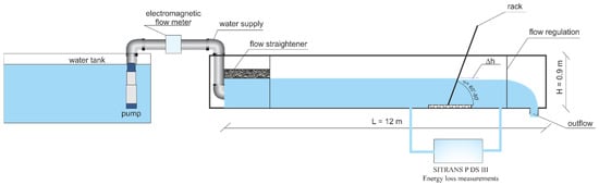
Figure 1.
Schematic of the measuring flume.
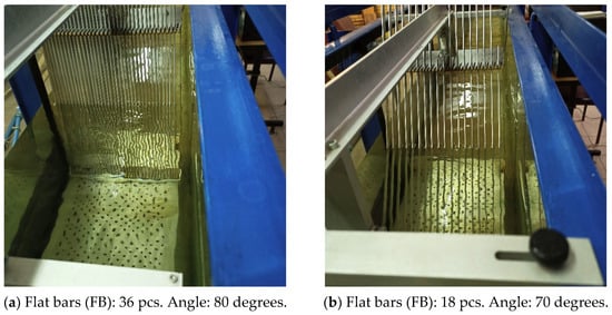
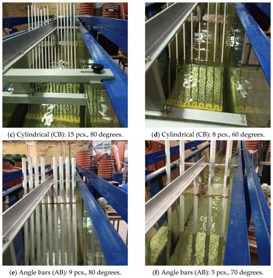
Figure 2.
Shapes and angles used in laboratory measurements.
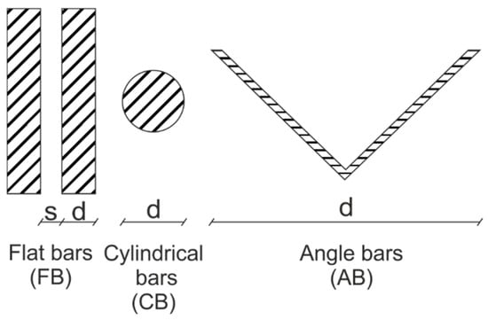
Figure 3.
List of bar shapes in the trash racks used in the analyses.
During laboratory tests, the depth of the water in front of and behind the trash racks was measured (using a manometer system). Measurements were carried out with a constant, regulated flow rate of Q = 0.027 m3·s−1 and a water depth in the channel of 0.55 m.
Three types of bars were tested: flat bars (FB), cylindrical bars (CB), and angle bars (AB) (Figure 3). The tests were carried out for trash racks at three different horizontal angles α of inclination, i.e., 60, 70, and 80 degrees for each type of bar, for different degrees of the blockage ratio for the trough sections—a different number of bars was used in the trash racks, i.e., 36 and 18 flat bars with 0.005 m and 0.012 m spacing (d/s = 0.40 and 0.17), 15 and 8 cylindrical bars with 0.015 m and 0.04 m spacing (d/s = 0.67 and 0.25), and 9 and 5 angle bars with 0.014 m and 0.056 m spacing (d/s = 1.93 and 0.48). First, the tests were performed for trash racks at an angle of 80° made of 36 flat bars (FB). After the flow was stabilised, a series of 30 measurements of the magnitude of losses Δh on the trash racks were taken (for a particular configuration of the trash rack). The averaged value was taken for further analysis. The process was repeated for another two grating angles, i.e., 70° and 60°. The trash racks were then diluted by removing every second bar, and the measurements were repeated successively for the angles of 60°, 70°, and 80°. After completing the measurements for one type of bar, the bars in the trash racks were replaced with another shape, and the whole procedure was repeated (Figure 4).
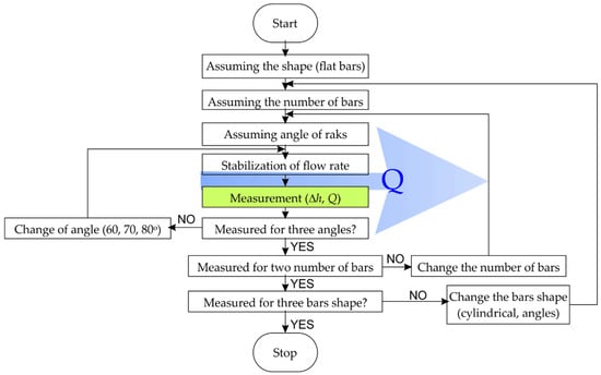
Figure 4.
Diagram of the steps of measurement.
The values of the hydraulic loss on the trash racks with known geometrical parameters of the bars and their inclination in the channel (from 90° to 30°) can be determined from the Kirschmer equation [49]:
where:
- β—loss coefficient depending on the shape of the bar and the angle of water inflow to the trash racks (-).
- α—the angle of inclination of the trash racks to the horizontal (°).
- d—thickness of the bar (m).
- s—spacing between the bars (spacing) (m).
- v0—water velocity in front of the grating (m·s−1).
Modifications to the above equation for the term have been proposed, among others, by Mosonyi [50], who added his own multiplicative term kδ [51]:
where:
- kf—shape factor of the trash racks.
- kδ—depends on the angle of the approaching flow relative to the bars and the blockage number b/e.
Idelchik [52] proposed an empirical relationship for different bar cross-sections, bar spacings, and angles of inclination to estimate height loss for bars parallel to the fluid flow. Clark et al. [44] proposed a similar but simpler equation, which they derived from laboratory tests for angles α between 90° and 60° and a constant thickness-to-spacing ratio of 4.41:
The equation takes into account the bar aspect ratio η, the angle δ between the flow direction and the bars, and the blocking factor P.
Meusburger [53] proposed an equation with a wider range, in which the loss factor β and the angle of the trash racks are coupled. The proposed modifications only apply to large spacings. The designations in the formula are similar to Clark’s equation, while kV is a coefficient that takes into account the size of the area of the trash racks blocked by debris:
Raynal et al. [41,54] conducted a study on fish-friendly trash racks. For sloped trash racks, they proposed an equation to determine head loss coefficients:
where kF is the bar shape coefficient, pb is the blockage ratio due to bars and outer bars (e.g., supporting structures), ps is the blockage ratio due to transversal elements (e.g., spacers), and C is the shape coefficient of the transversal elements, kα = sin2(α), where α is the angle to the horizontal.
During the measurements, the hydraulic loss was recorded Δh, which refers to the difference between the piezometric height before and after the trash racks. By transforming Equation (1) and knowing Δh, it is also possible to determine the loss coefficient on the trash racks depending on the geometry of the trash racks:
where:
- β—loss coefficient depending on the shape of the bar and the angle of attack of the water on the trash racks (-).
- α—the angle of inclination of the trash racks to the horizontal (°).
- d—thickness of the bar (m).
- s—spacing between bars (spacing) (m).
- v0—water velocity in front of the grating (m·s−1).
- Q—the volumetric flow rate (m3·s−1).
- A—the cross-sectional area of flow in front of the grating (m2); A = 0.55·0.47 = 0.2585 m2 = constant, where 0.55 is the water table level in the channel, and 0.47 is the width of the channel.
The measured average values of the losses Δh on the trash racks and the determined loss coefficients β (Equation (6)) on individual trash racks, depending on the angle of attack and bar count, were compared with each other.
3. Results
Measurements were carried out at a constant flow in the channel equal to Q = 0.027 m3·s−1 (mean = 0.027 m3·s−1, median = 0.027 m3·s−1, and standard deviation SD = 0.000174 m3·s−1, Figure 5). Velocity in front of the trash racks was assumed to be v0 = 0.1044 m·s−1 for the calculations, based on Equation (7).
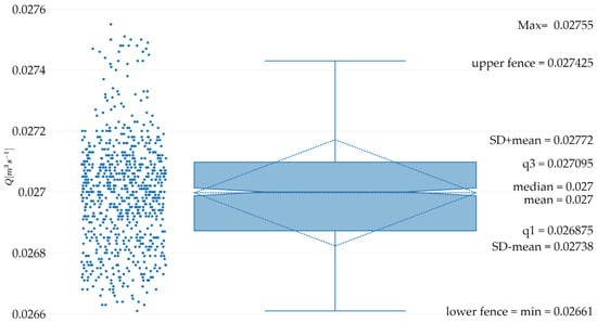
Figure 5.
Descriptive statistics for flume flow.
During the measurements, the hydraulic loss Δh of the trash racks was measured for each type of bar, its density, and the angle of inclination of the trash racks to the horizontal. Figure 6 summarises the averaged losses Δh on each set of trash racks, along with the determined standard deviations SD.
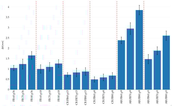
Figure 6.
Summary of losses on trash racks Δh for different types of bars, their density, and the inclination of the racks to the horizontal. The code XX.YY.pZ means: XX—type of bars (FB—flat bars, CB—cylindrical bars, and AB—angle bars), YY—angle α of inclination of gratings to the horizontal (°), and pZ—the number of bars (z) in the grating.
It is noticeable that the hydraulic loss Δh decreases as the number of bars in the trash racks decrease. Then, of course, the blockage ratio of the trash racks’ cross-section Ag/A0 decreases, where Ag is the area of the gratings, and A0 is the area of the cross-section of the trough (without gratings). As the angle of the trash racks from the horizontal increases, the average values of the losses increase on the grating. For 36 flat bars (FB) and an angle of 60°, the average value of the losses Δh is 1.044 mm ± SD = 0.129 mm, while for an angle of 80°, the average value of the losses is 1.65 mm ± SD = 0.189 mm (Figure 6 and Figure 7). For trash racks with a reduced number of flat bars (18 pcs.), the loss values are smaller, amounting to 0.996 mm ± SD = 0.204 mm and 1.26 mm ± SD = 0.186 mm for the angles 60° and 80°, respectively. An analogous trend was recorded for all types of trash racks (bar types), with the lowest losses recorded for trash racks with cylindrical bars (CB). Losses for the CB bars did not exceed 0.87 mm ± SD = 0.188 mm (the maximum value for 15 cylindrical bars and the angle α = 80°, Figure 6 and Figure 8). The minimum value of Δh = 0.49 mm ± SD = 0.127 mm was recorded for eight cylindrical bars (CB) and the angle α = 80°. Angle-bar (AB) trash racks were characterised by the greatest losses. The maximum average losses recorded during the measurements even reached Δh = 3.85 mm ± SD = 0.231 mm for trash racks made of 15 bars at an angle of α = 80° (Figure 6 and Figure 9).
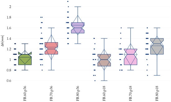
Figure 7.
Basic statistics for flat-bar (FB) trash racks (series codes as the same as in Figure 6).
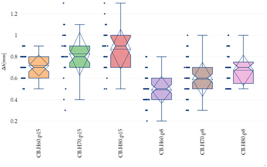
Figure 8.
Basic statistics for cylindrical-bar (CB) trash racks (series codes are the same as in Figure 6).
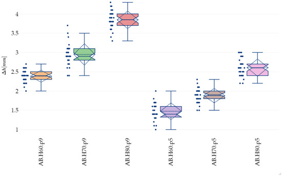
Figure 9.
Basic statistics for angle-bar (AB) trash racks (series codes are the same as in Figure 6).
The notches surrounding the median in Figure 7 indicate that for the series with flat bars (FB), the differences in the median mean Δh losses are significant. The notches show 95% confidence intervals for the medians and a distance of ± 1.58·IRQ·n0.5 (where IRQ—interquartile range, n—sample size) around the median [55]. Kernel density estimators (KDE) [56] have a low skewness, meaning that the median and mean of Δh losses lie very close to each other and near the centre of the interval (Figure 10).
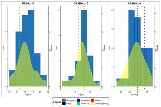
Figure 10.
Histograms and probability density distributions for selected trash racks (series codes are the same as in Figure 6).
Similarly, for trash racks with cylindrical bars (CB), which have the smallest average losses Δh, the position of the medians and notches (Figure 8) indicate that the differences in the medians of the average losses Δh are significant. The KDEs for trash racks with cylindrical bars and 15 notches and an angle of 60° and 8 notches and an angle of 80° indicate unimodal distributions, while in other cases, they have close to normal distributions. As in the case of flat bars, the median and mean of the losses Δh lie very close to each other and are near the centre of the interval.
For angle-bar (AB) trash racks, which have the highest average losses, with a maximum mean Δh = 3.85 mm, the position of the medians and the ranges of the notches (Figure 9) indicate that the differences in the medians of the mean losses Δh are significant. The KDE distributions for trash racks with five angle bars (AB) and inclination angle α = 60° for the trash racks indicate bi-modal distributions, while in other cases, they have close to normal distributions. As in the case of flat bars, the median and mean of Δh losses lie very close to each other and near the centre of the interval.
The measured and determined average values of hydraulic losses Δh allowed, based on Equation (6), the determination of the loss coefficients β for selected types of trash racks: the types of bars used, their density, and the angle of inclination. Figure 11 shows, for selected cases, the trend of the variation in parameter β as a function of the angle α of inclination of the trash racks. It can be observed that as the angle of inclination of the trash racks to the horizontal increases, the value of the β coefficient increases nonlinearly. The value of β also increases with an increase in the number of bars in the trash rack, and therefore increases with an increase in the blockage ratio in relation to the shape of the bars in the trash racks, as the active flow cross-section area is reduced.
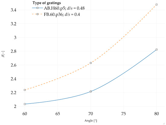
Figure 11.
Values of β coefficient for selected trash racks.
The obtained results of our research were related to literature data, obtaining a very satisfactory correlation (Figure 12 and Figure 13).
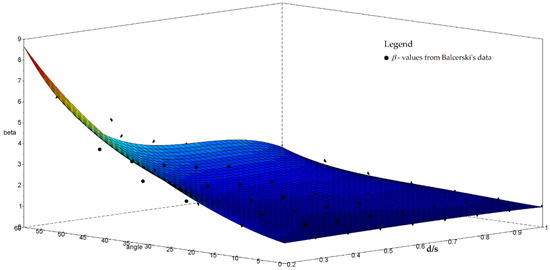
Figure 12.
Polynomial fitting of β. Own study based on the table [57].
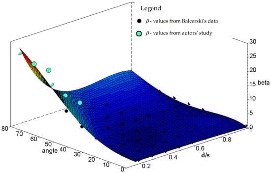
Figure 13.
Polynomial fitting of β including own measurements results.
Balcerski [57] tabulated the β coefficients for flat-bar trash racks as a function of the s/d ratio and the angle of inclination of the racks to the horizontal. Figure 12 shows the polynomial fitting of the surface for the polynomial degree n = 4 for Balcerski’s data using the function:
where the Ci coefficients represent the model parameters. The adjusted multivariate coefficient of determination for the fit surface for Balcerski’s data was 0.961. The authors also added their results for the trash racks (Figure 13), obtaining a new fitting surface for which the multivariate coefficient of determination was 0.956.
4. Discussion
This theoretical and experimental study allows us to conclude that the proper estimation of hydraulic losses on SHP trash racks can be somewhat difficult, and the obtained results are ambiguous. Many methods and equations are known for calculating the magnitude of energy losses, but often, the results that are obtained show rather large variation between methods. This can hinder the process of designing hydropower systems significantly. An excellent supplement to this process is then laboratory testing.
In the research presented here, the results obtained varied depending on the type of trash rack, the number and spacing (density) of the bars, and the angle of inclination of the trash rack relative to the horizontal. The highest losses, up to almost 4 mm, were observed on trash racks with angle bars (AB). These were almost eight times greater than those recorded on cylindrical-bar (CB) trash racks, for which the smallest head losses of Δh = 0.49 mm were obtained. However, it should be borne in mind that the cross-sectional coverage ratio for AB trash racks was also almost eight times greater than that for CB trash racks. In addition, the average losses Δh quoted above are extreme values in the present experiments and apply to other angles as well. However, this makes it clear that the discrepancy in the magnitude of losses on trash racks can be large and depends on the design and installation of the trash racks. Even within the same type of grating (the same types of bars mounted in the trash racks), depending on how the trash racks are mounted (angle of inclination), hydraulic losses can non-linearly increase by up to more than 70% for trash racks with angle bars (AB). For trash racks with flat bars, the increase in losses depending on the size of the angle α reached up to 60%, and for cylindrical ones (CB), almost 40%. Additionally, the values of the head-loss factor Δh for individual trash racks constructed from bars of different shapes varied non-linearly.
Similar observations and conclusions can be found in literature reports [17,18,34,45,47,51]. For example, Josiah et al. [34] analysed the effect of cylindrical bars on hydraulic loss values under laboratory conditions. In the experiment, they used bar spacings of 5 and 10 mm for bar diameters of 2, 3, 6, 8, and 10 mm and angles of inclination to the channel bottom that ranged from 30° to 90° in 15° increments. Measurements were carried out with flow rates ranging from 1 l·s−1 to 25 l·s−1. Measured losses ranged from a few mm to as much as almost 10 cm, depending on the type of trash racks and the bar blockage ratio, its angle of inclination to the horizontal, and the flow rate. These authors also proposed their equation for determining hydraulic losses depending on four parameters: α—inclination angle from channel bed, V—approach velocity, q—unit discharge, and p—blockage ratio.
Similar to the study we presented here, the impact of different bar profiles on hydraulic loss values on trash racks was also analysed by Lemkecher et al. [45]. They studied six different profiles, six different angles, and varying distances between bars. Based on their laboratory study, Lemkecher et al. [45] found that using the most efficient bar profile reduced the form factor kF (Equation (5)) by 40% compared to the hydrodynamic profile and by 67% compared to the conventional rectangular profile.
Our theoretical and experimental study also refers to the work of Böttcher et al. [17]. They determined the hydraulic loss Δh on trash racks with cylindrical-shaped bars and flexible fish fence (FFF) steel cables. The study was conducted for several different angles, densities, and flows (up to 230 l·s−1). Measured loss values ranged from a few mm to as much as 4 cm. As the blockage ratio increased, the pressure loss coefficient in the steel cables was up to 53% higher compared to in the cylindrical rods, which was probably related to the appearance of flow-induced cable vibrations. Similarly, Böttcher et al. [58] analysed head losses through an angled fish protection system in their previous experiments. The analysed values of the head losses Δh on the trash racks ranged from a few mm to about 3 cm.
Similar conclusions to those presented by us could also be reached when studying SHP trash racks in terms of the protection of migrating river ichthyofauna [18,51]. For example, in their study of fish-friendly trash racks, Szabo-Meszaros et al. [18] also analysed the magnitude of hydraulic losses, including various spatial orientations of the bars in the grating (vertical or horizontal). The trash racks were installed at a 30° angle to the side wall of the open trough. Three different bar configurations were analysed, along with Q flows ranging from 0.11 to 0.2 m3·s−1. Hydraulic losses ranged from a few mm to about 4 cm. A 43% difference was recorded between the head losses for the bars arranged vertically and for the bars arranged horizontally in the trash racks. The discussion presented above shows that the studies presented in this work relate well to literature reports and enhance the resource of hydraulic experimental data for SHP trash racks.
5. Summary and Conclusions
The efficiency of small hydropower plants is influenced by many factors: technical and hydrological, where the availability of water and changing flows in the river are decisive. They depend, inter alia, on the amount and frequency of summer (rain) and winter (snow) precipitation. Particularly dangerous are rapid snowmelt in spring and the associated higher water flows as well as summer floods after heavy rainfall and the associated greater transport of various types of river material (debris and trash). In such cases, power plant trash racks play a particularly important role. Their task is to catch migrating fish, larger pollutants, and debris, both of plant and anthropogenic origin, and thus protect the turbines of the power plant from failure and ensure their undisturbed operation. Therefore, an important issue is the proper selection and design of trash racks for SHPs so that they catch as many of the pollutants transported by the river as possible and prevent their movement into the turbine chamber. The spacing of the trash racks mainly depends on the size of the debris and the geometric dimensions of the turbine inlet. However, it must not be too small because dense trash racks result in a reduction in the disposable water head, which translates into economic losses in SHP power generation. Therefore, the correct selection of the right shape and geometry of SHP trash racks takes on particular importance in this context and is very important for the operation, protection, and formation of the river environment. The presented research, analyses, and literature data have shown that depending on the shape, geometry, and method of installation of trash racks, differences in height losses Δh can reach more than 40% and reach values of up to about 10 cm. Therefore, when relatively dense trash racks must be used in SHPs, the problem of selecting the hydraulically optimal shape of the bars (e.g., cylindrical) and the angle of inclination of the trash racks cannot be underestimated. It is worth noting that Kirschmer derived his mathematical formula for calculating Δh losses on trash racks based on laboratory experiments. The authors of the present paper, while studying various types and configurations of trash racks, which were also tested in the laboratory, among other things, created trash racks with characteristics similar to those of the gratings studied by Kirschmer (e.g., similar spacing between bars, the thickness of the bars, and the water velocity in front of the trash racks). The results of the measurements made it possible to determine, among other things, the β coefficients for the tested trash racks. They are comparable with literature data, e.g., the results obtained by Mosonyi [50,51] using the Kirschmer method (formulas 1, 2, 6), which indicates the correctness of the tests carried out and gives credence to the results obtained. The current state of knowledge regarding the hydraulics of trash racks for SHPs was also augmented. Among other things, the novelty of the research presented in this paper is the use of angle bars as a new bar shape for SHP trash racks and for the determination of the value of the β coefficient for them. They have the advantage of capturing more pollutants (a beneficial aspect of environmental protection) with a small number of bars, which is obviously related to the section blockage ratio. However, this is achieved at the price of higher hydraulic losses and lower economic benefits.
We should also emphasise the applied nature of the presented research, the results of which confirm the literature data [49]. According to the authors of this paper, after their own research, the Kirschmer formula and its modifications (e.g., according to Mosonyi [50,51]) can be recommended and used for the hydraulic calculation of trash racks for SHPs. It gives reliable results, is relatively simple and widely available, and is appropriate for engineering applications. However, it should be considered that Kirschmer’s formula is not universal for all cases, and further hydraulic studies of trash racks—especially for SHPs—will undoubtedly be valuable. In addition to the correct design of SHP trash racks, a separate and equally important problem concerns their correct operation, especially the systematic maintenance of the trash racks and cleaning the debris accumulated on them.
Author Contributions
Conceptualization, N.W. and Z.W.; methodology, N.W. and Z.W.; validation, N.W., Z.W. and T.T.; formal analysis, N.W., Z.W. and T.T.; investigation, N.W. and Z.W.; resources, N.W. and Z.W.; writing—original draft preparation, N.W., Z.W. and T.T.; writing—review and editing, N.W., Z.W. and T.T.; visualization, Z.W. All authors have read and agreed to the published version of the manuscript.
Funding
The publication was co-financed within the framework of Ministry of Science and Higher Education programme known as “Regional Initiative Excellence” for the years 2019–2022, Project No. 005/RID/2018/19.
Data Availability Statement
Not applicable.
Conflicts of Interest
The authors declare no conflict of interest.
References
- Wang, B.; Nistor, I.; Murty, T.; Wei, Y.-M. Efficiency assessment of hydroelectric power plants in Canada: A multi criteria decision making approach. Energy Econ. 2014, 46, 112–121. [Google Scholar] [CrossRef]
- Kodirov, D.; Tursunov, O. Calculation of water wheel design parameters for micro hydroelectric power station. E3S Web Conf. 2019, 97, 05042. [Google Scholar] [CrossRef]
- Tomaszewski, K.; Sekściński, A. Renewable energy sources in Poland-Local and regional perspectives. Rynek Energii 2020, 4, 10–19. (In Polish) [Google Scholar]
- Schnitzer, V. Micro Hydro Power; GTZ Ger and Hydro Power: Bammental, Germany, 2009; Volume 118. [Google Scholar]
- Boran, F.E.; Boran, K.; Menlik, T. The evaluation of renewable energy technologies for electricity generation in Turkey using intuitionistic fuzzy TOPSIS. Energy Sources Part B Econ. Plan. Policy 2012, 7, 81–90. [Google Scholar] [CrossRef]
- Koç, C. Problems and solutions related to hydroelectric power plants constructed on the Buyuk Menderes and the West Mediterranean Basin. Energy Sources Part Recovery Util. Environ. Eff. 2012, 34, 1416–1425. [Google Scholar] [CrossRef]
- Fakehinde, O.B.; Fayomi, O.S.; Efemwenkieki, U.K.; Babaremu, K.O.; Kolawole, D.O.; Oyedepo, S.O. Viability of hydroelectricity in Nigeria and the future prospect. Energy Procedia 2019, 157, 871–878. [Google Scholar] [CrossRef]
- Tan, Q.-F.; Wen, X.; Fang, G.-H.; Wang, Y.-Q.; Qin, G.-H.; Li, H.-M. Long-term optimal operation of cascade hydropower stations based on the utility function of the carryover potential energy. J. Hydrol. 2020, 580, 124359. [Google Scholar] [CrossRef]
- Jadoon, T.R.; Ali, M.K.; Hussain, S.; Wasim, A.; Jahanzaib, M. Sustaining power production in hydropower stations of developing countries. Sustain. Energy Technol. Assess. 2020, 37, 100637. [Google Scholar] [CrossRef]
- Nguyen-Tien, V.; Elliott, R.J.; Strobl, E.A. Hydropower generation, flood control and dam cascades: A national assessment for Vietnam. J. Hydrol. 2018, 560, 109–126. [Google Scholar] [CrossRef]
- Jiang, Z.; Li, R.; Li, A.; Ji, C. Runoff forecast uncertainty considered load adjustment model of cascade hydropower stations and its application. Energy 2018, 158, 693–708. [Google Scholar] [CrossRef]
- Guo, W.; Zhu, D. A review of the transient process and control for a hydropower station with a super long headrace tunnel. Energies 2018, 11, 2994. [Google Scholar] [CrossRef]
- Courret, D.; Larinier, M. Guide pour la Conception de Prises d’Eau “Ichtyo-Compatibles” pour les Petites Centrales Hydroélectriques [Guide for the Design of Fish-Friendly Intakes for Small Hydropower Plants]; Research Report No. Rapport GHAAPPE RA. 08.04; Agence de l’Environnement et de la Maîtrise de l’Energie (ADEME): Clermont-Ferrand, France, 2008. (In French) [Google Scholar]
- Larinier, M.; Travade, F. Downstream migration: Problems and facilities. Bull. Fr. Pêche Piscic. 2002, 364, 181–207. [Google Scholar] [CrossRef]
- Alp, A.; Akyüz, A.; Kucukali, S. Ecological impact scorecard of small hydropower plants in operation: An integrated approach. Renew. Energy 2020, 162, 1605–1617. [Google Scholar] [CrossRef]
- Čarija, Z.; Lučin, I.; Lučin, B.; Grbčić, L. Investigation of Numerical Simulation Parameters on Fluid Flow around Trash-Racks. In Proceedings of the 29TH DAAAM International Symposium on Intelligent Manufacturing and Automation, Zadar, Croatia, 24–27 October 2018; DAAAM International: Vienna, Austria, 2018; Volume 29, pp. 1046–1052. [Google Scholar]
- Böttcher, H.; Gabl, R.; Aufleger, M. Experimental hydraulic investigation of angled fish protection systems—Comparison of circular bars and cables. Water 2019, 11, 1056. [Google Scholar] [CrossRef]
- Szabo-Meszaros, M.; Navaratnam, C.U.; Aberle, J.; Silva, A.T.; Forseth, T.; Calles, O.; Fjeldstad, H.-P.; Alfredsen, K. Experimental hydraulics on fish-friendly trash-racks: An ecological approach. Ecol. Eng. 2018, 113, 11–20. [Google Scholar] [CrossRef]
- Chang, F.F.; Shen, H.W. Debris Problems in the River Environment; FHWA-RD-79-62; Federal Highway Administration: Washington, DC, USA, 1979.
- Diehl, T.H. Potential Drift Accumulation at Bridges; US Department of Transportation, Federal Highway Administration, Research and Development Turner-Fairbank Highway Research Center: McLean, VA, USA, 1997.
- Hribernik, A. Evaluation of clogged hydropower plant trash rack losses. Stroj. Vestn. Mech. Eng. 2020, 66, 142–152. [Google Scholar] [CrossRef]
- Perham, R.E. Floating Debris Control: A Literature Review; U.S. Army Cold Regions Research and Engineering Laboratory: Vicksburg, MS, USA, 1987. [Google Scholar]
- Wallerstein, N.P.; Thorne, C.R.; Abt, S.R. Debris control at hydraulic structures—Management of woody debris in natural channels and at hydraulic structures; US Corps of Engineers, Waterways Experiment Station: Vicksburg, MS, USA, 1996. [Google Scholar]
- Blanc, J. An Analysis of the Impact of Trash Screen Design on Debris Related Blockage at Culvert Inlets. Ph.D. Thesis, Heriot-Watt University, Edinburgh, UK, 2013. [Google Scholar]
- Bradley, J.B.; Richards, D.L.; Bahner, C.D. Debris Control Structures-Evaluation and Countermeasures: Hydraulic Engineering Circular 9; Federal Highway Administration, Office of Bridge Technology: Washington, DC, USA, 2005.
- Zayed, M.; Farouk, E. Effect of blocked trash rack on open channel infrastructure. Water Pract. Technol. 2021, 16, 247–262. [Google Scholar] [CrossRef]
- Gamal, T. Design and Operation of Floating Weed’barriers for Controlling Scour in Open Channels. Ph.D. Thesis, Faculty of Engineering, Ain Shams University, Cairo, Egypt, 2014. [Google Scholar]
- Tyler, R.N. River Debris: Causes, Impacts, and Mitigation Techniques. Prepared for: Ocean Renewable Power Company; Alaska Center for Energy and Power: Fairbanks, AK, USA, 2011; pp. 1–33. [Google Scholar]
- Stockstill, R.L.; Daly, S.F.; Hopkins, M.A. Modeling floating objects at river structures. J. Hydraul. Eng. 2009, 135, 403–414. [Google Scholar] [CrossRef]
- Tamagni, S.; Weitbrecht, V.; Müller, U.; Hunziker, R.; Wyss, H.; Kolb, R.; Baumann, W. Schwemmholzrückhalt Ettisbühl/Malters. Wasser Energ. Luft 2010, 102, 269–274. [Google Scholar]
- Weitbrecht, V.; Rüther, N. Laboratory and Numerical Model Study on Sediment Transfer Processes in an Expanding River Reach. In Proceedings of the 33rd IAHR Congress: Water Engineering for a Sustainable Environment, Vancouver, BC, Canada, 9–14 August 2009; IAHR: Madrid, Spain, 2009; pp. 5436–5443. [Google Scholar]
- Walczak, N.; Walczak, Z.; Nieć, J. Influence of debris on water intake gratings in small hydroelectric plants: An experimental study on hydraulic parameters. Energies 2021, 14, 3248. [Google Scholar] [CrossRef]
- Elder, J.W. Steady flow through non-uniform gauzes of arbitrary shape. J. Fluid Mech. 1959, 5, 355–368. [Google Scholar] [CrossRef]
- Josiah, N.R.; Pathirana, K.P.P.; Tissera, H.P.S. An experimental investigation of head loss through trash racks in conveyance systems. J. Inst. Eng. Sri Lanka 2016. [Google Scholar] [CrossRef]
- Orsborn, J.F. Rectangular-bar trashrack and baffle headlosses. J. Power Div. 1968, 94, 111–123. [Google Scholar] [CrossRef]
- Taylor, G.I.; Batchelor, G.K.; Dryden, H.L.; Schubauer, G.B. The effect of wire gauze on small disturbances in a uniform stream. Q. J. Mech. Appl. Math. 1949, 2, 1–29. [Google Scholar] [CrossRef]
- Wahl, T.L. Trash Control Structures and Equipment: A Literature Review and Survey of Bureau of Reclamation Experience; U.S. Bureau of Reclamation: Washington, DC, USA, 1992.
- Yeh, H.H.; Shrestha, M. Free-surface flow through screen. J. Hydraul. Eng. 1989, 115, 1371–1385. [Google Scholar] [CrossRef]
- Tsikata, J.M.; Tachie, M.F.; Katopodis, C. Particle image velocimetry study of flow near trashrack models. J. Hydraul. Eng. 2009, 135, 671–684. [Google Scholar] [CrossRef]
- Tsikata, J.M.; Tachie, M.F.; Katopodis, C. Open-channel turbulent flow through bar racks. J. Hydraul. Res. 2014, 52, 630–643. [Google Scholar] [CrossRef]
- Raynal, S.; Chatellier, L.; Courret, D.; Larinier, M.; David, L. An experimental study on fish-friendly trashracks—Part 2. Angled trashracks. J. Hydraul. Res. 2013, 51, 67–75. [Google Scholar] [CrossRef]
- Zayed, M.; El Molla, A.; Sallah, M. An experimental study on angled trash screen in open channels. Alex. Eng. J. 2018, 57, 3067–3074. [Google Scholar] [CrossRef]
- Zayed, M.; El Molla, A.; Sallah, M. An experimental investigation of head loss through a triangular “V-shaped” screen. J. Adv. Res. 2018, 10, 69–76. [Google Scholar] [CrossRef]
- Clark, S.P.; Tsikata, J.M.; Haresign, M. Experimental study of energy loss through submerged trashracks. J. Hydraul. Res. 2010, 48, 113–118. [Google Scholar] [CrossRef]
- Lemkecher, F.; Chatellier, L.; Courret, D.; David, L. Contribution of different elements of inclined trash racks to head losses modeling. Water 2020, 12, 966. [Google Scholar] [CrossRef]
- Albayrak, I.; Kriewitz, C.R.; Hager, W.H.; Boes, R.M. An experimental investigation on louvres and angled bar racks. J. Hydraul. Res. 2017, 56, 59–75. [Google Scholar] [CrossRef]
- Latif, M.A.; Sarwar, M.K.; Farooq, R.; Shaukat, N.; Ali, S.; Hashmi, A.; Tariq, M.A.U.R. Estimating energy efficient design parameters for trash racks at low head hydropower stations. Water 2022, 14, 2609. [Google Scholar] [CrossRef]
- Baselt, I.; Malcherek, A. Determining the flow resistance of racks and the resulting flow dynamics in the channel by using the Saint-Venant equations. Water 2022, 14, 2469. [Google Scholar] [CrossRef]
- Kirschmer, O. Untersuchungen über den Gefällsverlust an Rechen; Oldenbourg Wissenschaftsverlag: Munich, Germany, 1926. [Google Scholar]
- Mosonyi, E. Wasserkraftwerke; VDI-Verlag: Berlin, Germany, 1966; Volume 1, ISBN 3-18-400133-4. [Google Scholar]
- Hack, H.P. Wasserkraftniederdruckanlagen, Kraftwerk und Stauraum, Kleinwasserkraftwerke. W. In Flussbau. Hydraulische Berechnung, Wehre und Sohlenbauwerke, Ausleitungsbauwerke, Energieumwandlungsanlagen, Wasserkraftanlagen, Binnenverkehrswasserbau; Universitätsverlag Weimar: Weimar, Germany, 2007; pp. 263–344. ISBN 978-3-86068-326-2. [Google Scholar]
- Idelchik, I.E. Handbook of Hydraulic Resistance, 2nd ed.; Rev. and Augmented; Hemisphere Publishing Corp: London, UK, 1986; ISBN 978-1-56700-251-5. [Google Scholar]
- Meusburger, H. Energieverluste an Einlaufrechen von Flusskraftwerken. Ph.D. Thesis, ETH Zürich, Zürich, Switzerland, 2002. [Google Scholar]
- Raynal, S.; Courret, D.; Chatellier, L.; Larinier, M.; David, L. An experimental study on fish-friendly trashracks—Part 1. Inclined trashracks. J. Hydraul. Res. 2013, 51, 56–66. [Google Scholar] [CrossRef]
- McGill, R.; Tukey, J.W.; Larsen, W.A. Variations of Box Plots. Am. Stat. 1978, 32, 12–16. [Google Scholar] [CrossRef]
- Chen, Y.-C. A tutorial on kernel density estimation and recent advances. Biostat. Epidemiol. 2017, 1, 161–187. [Google Scholar] [CrossRef]
- Balcerski, W. Inland Waterway Structures; Bud. Betonowe, Arkady: Warszawa, Poland, 1969. (In Polish) [Google Scholar]
- Böttcher, H.; Gabl, R.; Ritsch, S.; Aufleger, M. Experimental Study of Head Loss through an Angled Fish Protection System. In Proceedings of the 4th IAHR Europe Congress, Liege, Belgium, 7–29 July 2016; Dewals, B., Ed.; CRC Press: Liege, Belgium, 2016; pp. 637–642. [Google Scholar]


Publisher’s Note: MDPI stays neutral with regard to jurisdictional claims in published maps and institutional affiliations. |
© 2022 by the authors. Licensee MDPI, Basel, Switzerland. This article is an open access article distributed under the terms and conditions of the Creative Commons Attribution (CC BY) license (https://creativecommons.org/licenses/by/4.0/).