Abstract
Blast furnace gas is the major combustible by-product produced in the steel industry, where iron ore is reduced by coke into iron. Direct combustion of blast furnace gas after simple treatment for power generation is a common utilization method nowadays. However, this method suffers from low efficiency and high carbon intensity. The use of gas-steam combined cycle is an excellent method to improve the efficiency of blast furnace gas for power generation. However, there is a problem of insufficient utilization of low product heat, and the addition of CCS system can further reduce the power efficiency. To solve these issues, a new blast furnace gas power generation system with a Brayton cycle with supercritical CO2 and a Rankine cycle with transcritical CO2 is proposed in this work. The new system is then thermodynamically simulated by Aspen Plus, after the sub-modules are validated. The effects of molar ratio of steam to carbon, selexol/CO2 mass ratio, compression ratio, turbine import temperature and turbine inlet pressure on the system are investigated. A comparison is also performed between the new combined cycle system and the traditional combined cycle power generation system. The results show that in the new power generation system, net power efficiency of 53.29%, carbon capture efficiency of 95.78% and sulfur capture rate of 94.46% can be achieved, which is significantly better than the performance of the conventional combined cycle.
1. Introduction
Blast furnace gas (BFG) is an important exhaust gas produced in the steel industry, where iron ore is reduced by coke into iron. BFG has a low calorific value, but has the highest production in steel industry gas. The rational utilization of BFG is of great significance for energy conservation and emission reduction [1]. Campos [2] reported an exergy-based comparison between BFG-fueled combined cycle plants and steam cycle plant configurations, providing a method of direct combustion of blast furnace gas for power generation. Campos [3] compared the efficiency of combined cycle and Rankine cycle in BFG utilization, showing that the combined cycle has higher power generation efficiency. Ryzhkov [4] discussed the worldwide practice of operating combined cycle power plants on BFG to date, and the principles of upgrading a standard gas turbine power plant to a combustion BFG were studied.
Though combined cycle gas turbine (CCGT) is efficient and currently used, its thermal efficiency can be further improved by utilization of low product heat. Wang et al. [5] surveyed the application of gas-steam combined cycle and subcritical gas power generation in the metallurgical industry, and the expected efficiency could reach 43%. Hou et al. [6] adopted Brayton cycle with supercritical CO2 and organic Ranking cycle in CCGT to recycle residual heat, which resulted in a 62.23% CCGT efficiency, which demonstrated the application of Brayton cycle with supercritical CO2 and organic Ranking cycle to improve the combined cycle’s efficiency.
The Brayton cycle with supercritical CO2 has a comparatively high efficiency over a wide temperature range [7]. The efficiency of Brayton cycle with supercritical CO2 at 550~750 °C is higher than that of the Rankine cycle with steam or helium as working fluid. Thus, the use of supercritical CO2 as the working fluid in the Brayton cycle can significantly reduce the power consumption of the compressor and achieve a cycle efficiency of at least 35% [8]. Yang [9] studied the effects of inflow pressure and temperature on Brayton cycle with supercritical CO2, and the highest efficiency of the supercritical CO2 Brayton cycle can reach 65%. Pan [10] applied supercritical CO2 Brayton cycle to recover waste heat of combined cycles gas turbine and the energy efficiency of the entire system was increased by 7.03% with the supercritical CO2 Brayton cycle, compared with the condition that gas turbine without recovery of waste heat.
Power cycle with transcritical CO2 has many advantages over conventional power cycles for low-grade heat source recovery [11,12]. This is mainly because the temperature profile of transcritical CO2 can better matches the heat source temperature than other pure working fluids, and its heat transfer performance is better than that of mixed fluids, which makes the cycle more efficient [13]. Chen et al. [14] compared Rankine cycle with transcritical CO2 with organic Rankine cycle and showed that the power output of the Rankine cycle with transcritical CO2 is slightly higher than the power of the organic Rankine cycle in utilization of the low-grade heat source with the same average thermodynamic heat rejection temperature. Habibollahzade et al. [15] studied transcritical CO2, supercritical CO2 cycle and compared in simple Rankine, which showed that Rankine cycle with transcitical CO2 is best because they lead to higher efficiency while having a satisfactory total cost rate under well-balanced conditions. These studies showed that Rankine cycle with transcritical CO2 has advantages in utilizing the low-grade heat source.
Carbon capture and storage (CCS) is a technology that separates CO2 from industrial and energy sector emission sources and transport it for long-term isolation from the atmosphere to safe storage sites [16], which has great significance to Chinese carbon peak and neutrality targets [17,18]. However, it is difficult to balance carbon capture rate and energy consumption. Sun et al. [19] incorporated CCS technology into a combined cycle field, and demonstrated that the carbon capture rate could reach 70%. Chen et al. [20] studied the effect of the CCS system on IGCC and determined that the efficiency of power generation was decreased to 35.16%, and the carbon capture rate was 90% after adding the CCS system. These studies showed that higher carbon capture rates come at the cost of power generation efficiency.
The literature review shows that the existing CCGT systems have high low-grade heat losses, low efficiency after adding the CCS system and waste exergy. The efficiency of CCGT with CCS is usually blow 40%. The Brayton cycle with supercritical CO2 and the Rankine cycle with transcritical CO2 have an excellent performance in the utilization of low-grade heat, which can be a substitute for the traditional Rankine cycle. To improve the efficiency of CCGT systems and to rationally use low-grade heat, a new type of combined cycle power generation system is proposed in this paper. The new combined cycle system adopts both a Brayton cycle with supercritical CO2 and a Rankine cycle with transcritical CO2 to improve overall efficiency and uses polyethylene glycol dimethyl ether to adsorb CO2 to reduce energy losses. The main conclusions of this paper are of reference value for future practical operation and performance optimization of similar power plants.
2. New Power Generation System
2.1. Exergy Calculation
In a system, heat energy consists of exergy, which is the usable energy and anergy which is the unusable energy. Exergy represents the maximum work that can be obtained by the whole system consisting of both system and surroundings when the system is balancing with surroundings [21]. Anergy represents the part of energy that cannot be transformed into work even by reversible processes [22]. Therefore, the energy depends on the state and environment of the system. Exergy usually consists of both physical exergy and chemical exergy in thermodynamic system analysis, as Equation (1):
where represents total exergy and and represent the physical exergy and chemical exergy, respectively. The actual physical exergy of a flowing stream can be calculated from Equation (2):
where and are the represents of the specific molar enthalpies of a flowing stream at practical conditions (T, p) and environmental condition (T0, p0), and s and s0 represents the specific molar entropy of a flowing water stream under actual and ambient conditions. The specific chemical exergy of a gas mixture can be calculated by Equation (3):
where represents the gas constant and represents the standard chemical molar exergy of species i. In the standard state (298.15 K, 101.325 K Pa), the chemical energies of the different substances can be found in the literature [23].
The basic methods of exergy analysis are based on the exergy balance equation (EXBE). For an environmentally connected system operating at steady state, if kinetic and potential energy are neglected, the EXBE can be written in the following form:
where is the loss of exergy in a unit, and denote the inlet and outlet exergies, is the unit output work. is calculated as in Equation (5):
So the exergy efficiency of a system can be calculated using Equation (6)
2.2. General Description
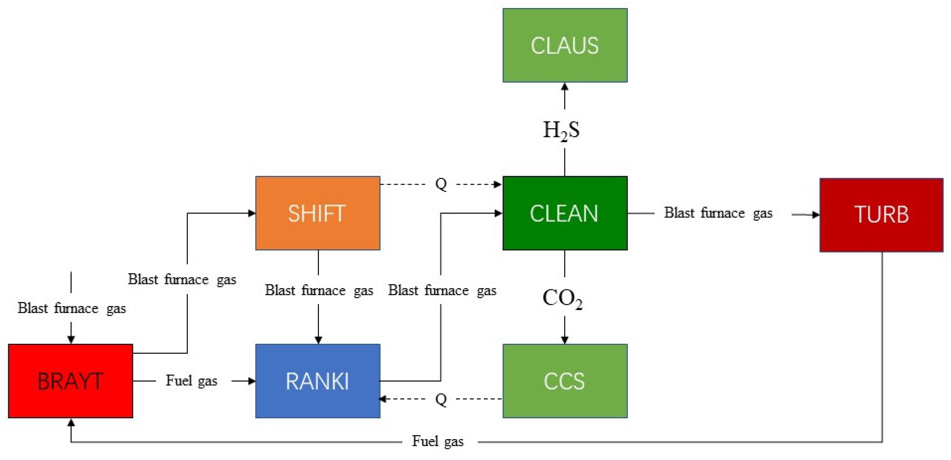
The flow diagram of the simulation system is shown in Figure 1. SHIFT is the water-gas conversion reaction subsystem. CLEAN is the raw gas clean subsystem with DEPG. CLAUS is the Claus subsystem for sulfur generation. TURB is the gas turbine cycle for power generation. BRATY is the Brayton cycle with supercritical CO2. RANKI is the Rankine cycle with transcritical CO2. CCS is the carbon capture and sequestration system. In the gas conversion unit (SHIFT), CO reacts with H2O to produce high calorific value hydrogen, the purification unit (CLEAN) cleans the syngas by removing most of the H2S and CO2, and the CO2 compression unit (CCS) compresses the CO2 separated from the CLEAN into a liquid to achieve CO2 capture. In the gas turbine unit (TURB), the clean syngas from the CLEAN is mixed with N2 and then air before entering the gas turbine to generate electricity. High-temperature flue gas exiting the TURB is the heat source for the Brayton cycle with supercritical CO2 (BRAYT) to generate electricity to provide the heat required for the cycle. In the Rankine cycle with transcritical CO2 unit (RANKI), syngas and flue gas from the Brayton cycle with supercritical CO2, syngas from the SHIFT, and water from the CCS to absorb waste heat are used as the heat source for the Rankine cycle with transcritical CO2 to provide the heat required for the cycle.

Figure 1.
Schematic flow chart of the simulated system.
2.3. SHIFT Module
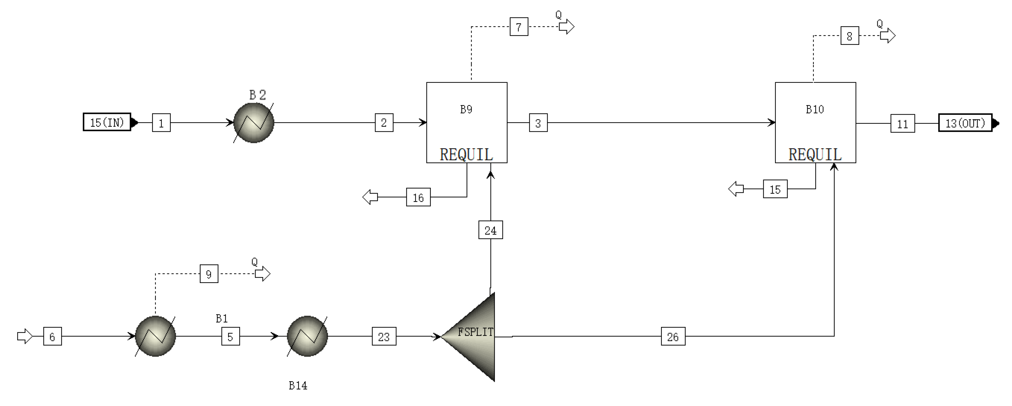
A schematic of the SHIFT module is shown in Figure 2. The inlet substances of the SHIFT module are gas and water. The high-temperature gas is cooled and enters the latter two stages of the reactor, where it reacts with water vapor under the action of a catalyst. The main reaction equation is as in Equation (7):
CO + H2O = CO2 + H2
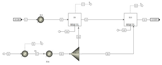
Figure 2.
A schematic of the SHIFT module flowsheet.
The water in the SHIFT module is passed through a separator proportionally to the two-stage reactor, where it reacts with the gas [24].
The data projected and reported [25] for the SHIFT subunit are shown in Table 1. Table 2 shows the materials and parameters of all streams in SHIFT module.

Table 1.
Comparison of subunit forecasts with reported data of SHIFT.
Table 2.
Stream parameters in SHIFT.
2.4. CLAUS Module
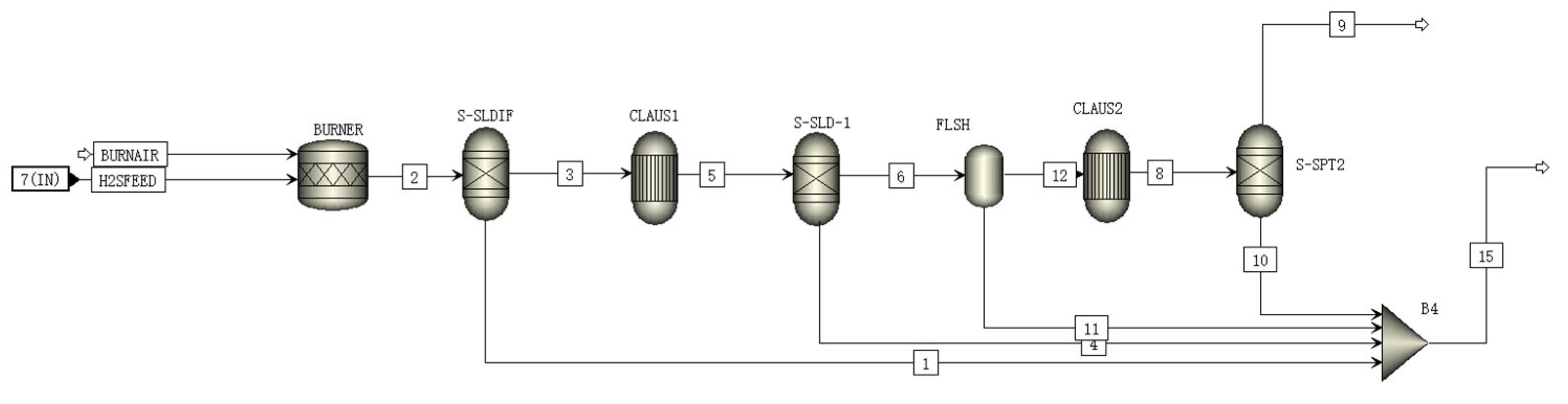
A schematic of the CLAUS module is shown in Figure 3. The inlet substances in the CLAUS module are H2S and air. H2S is oxidized to SO2 by air in the burner according to Equation (8):
H2S + 1.5O2 = H2O + SO2
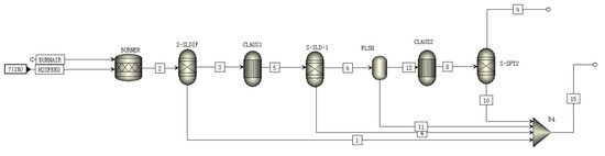
Figure 3.
A schematic of the CLAUS module flowsheet.
The generated SO2 further reacts with the incompletely reacted H2S in the converter to form sulfur monomers and water according to Equation (9):
2H2S + SO2 = 2H2O + 3S
Sulfur crystals generated in the converter are extracted and recovered by the separator as sulfur trapping [26]. The extracted vapor flows into the CLAUS reactor, where the generation and extraction of sulfur crystals are repeated, serving to enhance the CLAUS reaction [27].
Table 3 shows the predicted and reported data [28] for the CLAUS subunits. Table 4 shows the materials and parameters of all streams in CLAUS module.
Table 3.
Comparison of subunit forecasts with reported data of CLAUS.
Table 4.
Stream parameters in CLAUS.
2.5. CLEAN Module
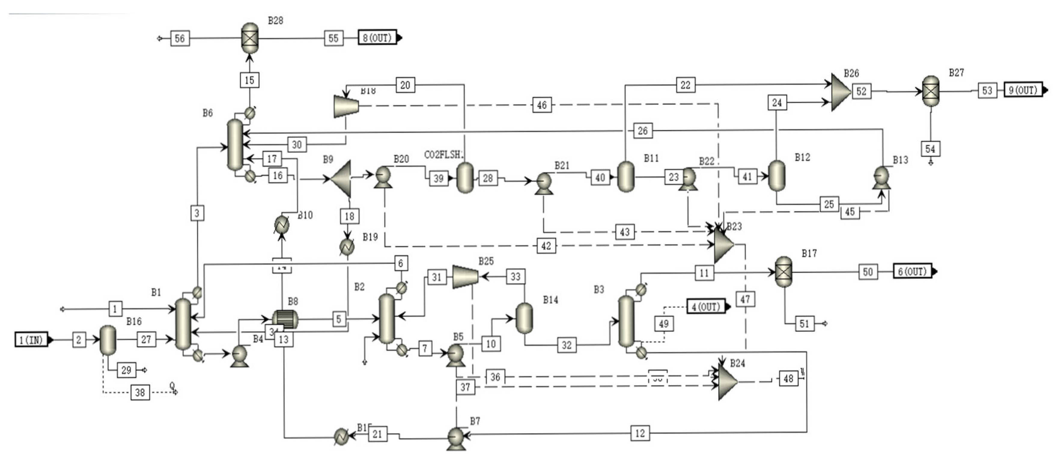
A schematic of the CLEAN module is shown in Figure 4. In the H2S absorber, the SELEXOL solution absorb most of the H2S and some of the CO2 in the gas [29]. The absorbed H2S is stripped in the H2S stripper and the absorbed CO2 is then stripped in the CO2 stripper and flows back to the H2S absorber. The gas from the H2S absorber then flows to the CO2 absorber where most of the CO2 is captured by the SELEXOL solution. The captured CO2 is then released in the flash tank, producing virtually cleaned CO2 and renewing the SELEXOL solution.
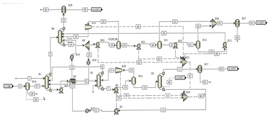
Figure 4.
A schematic of the CLEAN module flowsheet.
The absorption efficiency of CO2 and H2S of the CLEAN subunit are 97% and 95%, which is proximate to the reported data [30]. Table 5 shows the materials and parameters of all streams in CLEAN module.
Table 5.
Stream parameters in CLEAN.
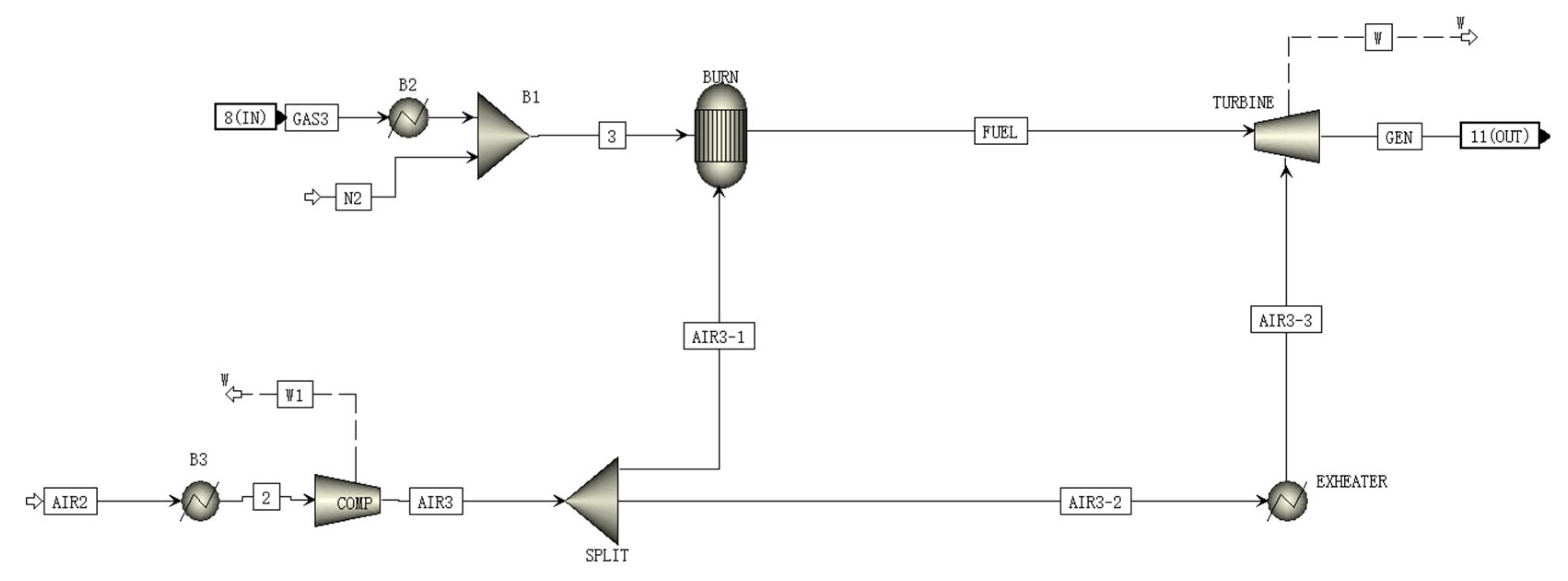
2.6. TURB Module
A schematic of the TURB is shown in Figure 5. N2 is mixed in the synthesizer at the inlet of the TURB model. The mixed gas then enters the combustor for combustion along with one part of the compressed air from the compressor. The high temperature flue gas is then mixed with another part of the compressed air and enters the gas turbine and expands for expansion work to drive the gas turbine to generate power.

Figure 5.
A schematic of the TURB module flowsheet.
The predicted results of TURB subunits are compared against the data reported in the literature [31], which are shown in Table 6. Table 7 shows the materials and parameters of all streams in TURB module.
Table 6.
Comparison of subunit forecasts with reported data of TURB.
Table 7.
Stream parameters in TURB.
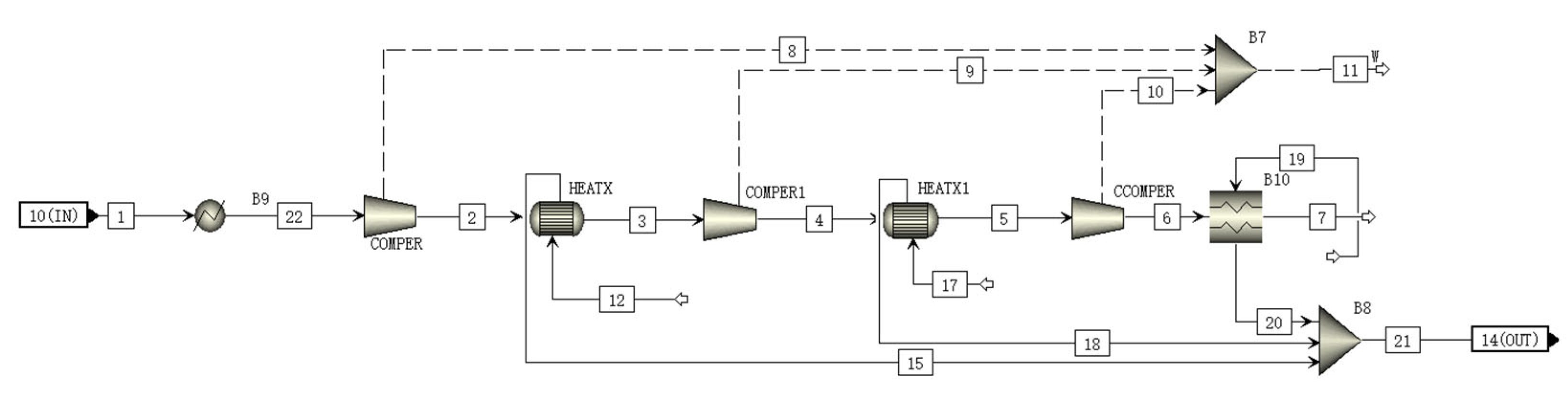
2.7. CCS Module
The CCS module uses a multistage compressor to compress CO2, which is in a subcritical liquid state, after the multistage compression [32,33]. To maximize the use of the heat produced by the compressor, a heat exchanger is added between the compressors of each stage, and the collected heat can be used to heat the Rankine cycle with transcritical CO2. A schematic of the CO2 compression module is shown Figure 6. Table 8 shows the materials and parameters of all streams in CCS module.
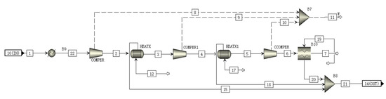
Figure 6.
A schematic of the CCS module flowsheet.
Table 8.
Stream parameters in CCS.
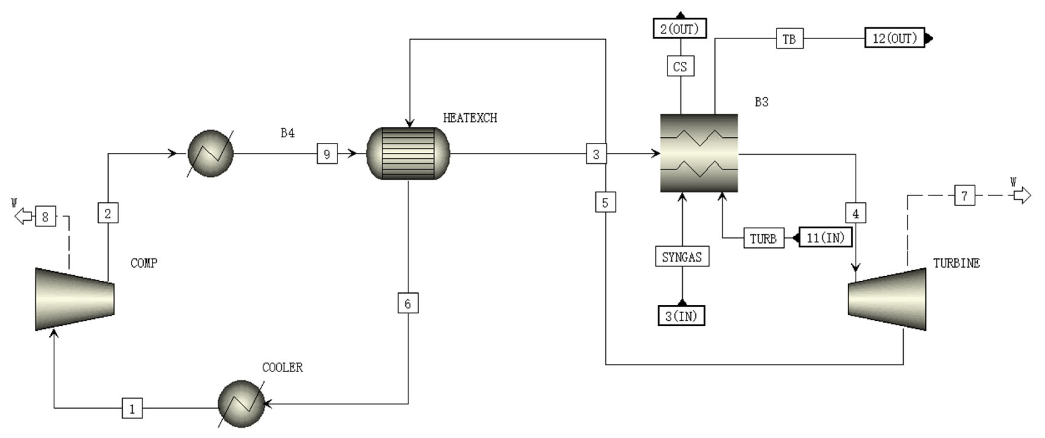
2.8. Supercritical CO2 Brayton Cycle Module (BRAYT Module)
A schematic of the BRAYT module is shown in Figure 7. In the BRAYT module, the supercritical CO2 is compressed to between 7.63 and 20 MPa, and the high-pressure supercritical CO2 is heated to 550 °C by the heat exchanger and heat sink. It then expands to 7.63 MPa in the turbine to generate electricity, and the expanded CO2 from the heat exchanger flows back to the compressor to complete a cycle [34].
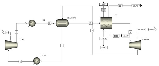
Figure 7.
A schematic of the BRAYT module flowsheet.
The temperatures of CO2 in streams 2, 3, 5 and 6 in Figure 6 are 71.5 °C, 338.4 °C, 436.1 °C and 81.0 °C, which are close to the reported data of 65.9 °C, 323.9 °C, 434.7 °C and 75.4 °C, respectively [35]. Table 9 shows the materials and parameters of all streams in BRAYT module.
Table 9.
Stream parameters in BRAYT.
2.9. Transcritical CO2 Rankine Cycle Module (RANKI Module)
A schematic of the RANKI module is shown in Figure 8. In the RANKI module, subcritical CO2 is pressurized to 17 MPa by the pump. This high-pressure CO2 passes through the heat exchanger and is heated to become supercritical CO2 which has high temperature and high pressure. The high-temperature and high-pressure CO2 is further heated by the sensible heat of the CCS, BRATY, and SHIFT after passing through the heat exchanger for further waste heat utilization. After this, the supercritical CO2 flows into the turbine, expands, and generates electricity. The expanded CO2 is then cooled to the liquid in the condenser, and flows to the pump again to complete a Rankine cycle with transcritical CO2.
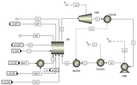
Figure 8.
A schematic of the RANKI module flowsheet.
Comparing the thermal efficiency with the literature [28], the predicted thermal efficiency is 23.8%, which closes to the reported data 23.6%. Table 10 shows the materials and parameters of all streams in RANKI module.
Table 10.
Stream parameters in RANKI.
3. Characterization of the New System
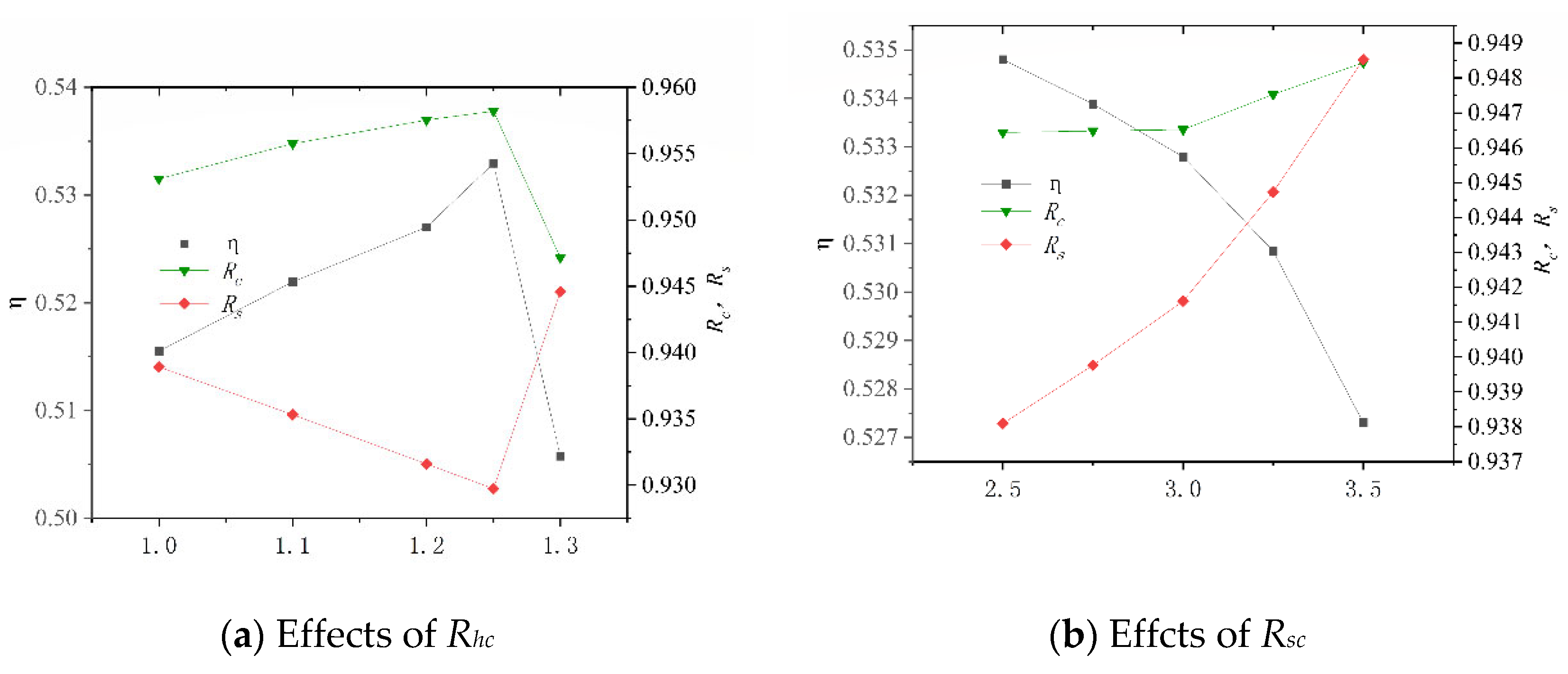
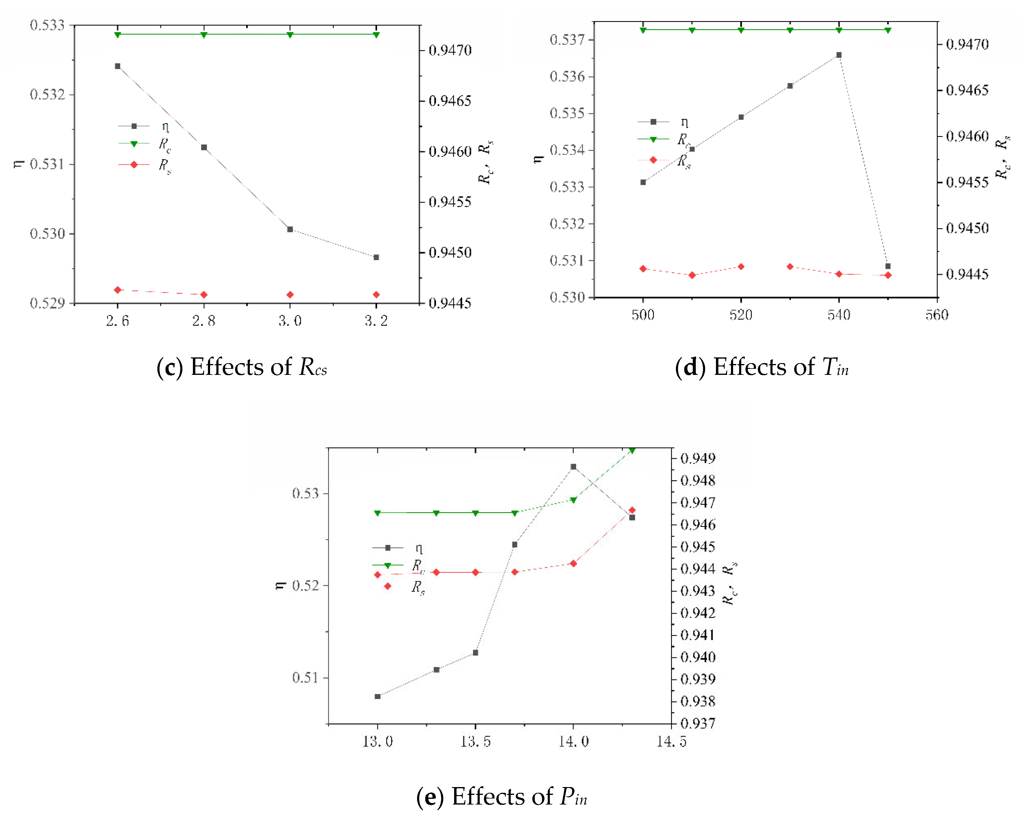
After its construction, the system was numerically simulated, and the key operating parameters of the system and their variation ranges are shown in Table 11. These data are derived by changing the molar ratio of steam to carbon (Rhc) in the SHIFT module, the mass ratio of Selexol solution to CO2 (Rsc) in the CLAUS module, the compression ratio (Rcs) and the inlet temperature of turbine (Tin) in the BRATY module, and the inlet pressure of turbine (Pin) in the RANKI module. Their effects on the net electrical efficiency (η), carbon capture rate (Rc), and sulfur capture rate (Rs) of the system are presented in Figure 9. In particular, the system is unstable when Rcs is less than 2.6 and Tin is greater than 550, so the Rcs values are all greater than 2.6, and Tin is less than 550.
Table 11.
Module operation parameters of the system.
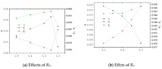
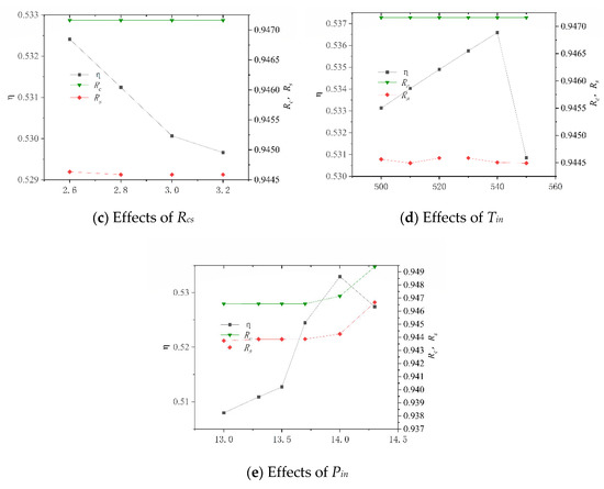
Figure 9.
Effects of different working parameters on the system performance.
Figure 9a shows that as Rhc increases, η increases before decrement. This is because the H2 increased due to increased water. Excessive water consumes more heat and results in an increased conversion ratio of carbon to sulfur. It is also noted that the variation in Rs is more sensitive than that in Rc, which is due to the amount of CO2 in the syngas being much larger than the amount of H2S. From Figure 9b, it is seen that η decreases with increasing Rsc while Rc and Rs all increase. This is because the increased amount of SELEXOL requires higher thermal energy consumption and more electricity to circulate the solution. As Rcs increases, η decreases, and Rc and Rs essentially remain constantly, as shown in Figure 9c. It can be seen from Figure 9d that as Tin increased, η increases and then decrease, and Rc and Rs essentially remain the same. When Pin is less than 14 MPa, η rises as Pin increases, as shown in Figure 9e. When Pin is greater than 14 MPa, the rule is reversed, and Pin has less effect on Rc and Rs when it is less than 14 MPa.
Exergy refers to the maximum value of useful work that can be released when the system changes from the state it is into the ambient state. Exergy analysis can reflect the gap between the theoretical and actual useful work that can be released by the system. From Table 12, the exergy flux of each module can be calculated. Heat exergy represents the exergy of the heat input into the unit, and when the system absorbs heat from surroundings, the heat exergy is negative value. Similarly, power exergy is equal to the work output from the unit, and if the unit output works, the power is negative value. The exergy efficiencies of the SHIFT module, the CLAUS module, the CLEAN module, the TURB module, the BRATY module, the RANKI module and CCS module are found to be 95.06%, 79.74%, 79.73%, 59.03%, 98.45%, 87.01%, 99.93%, respectively. Supercritical CO2 Brayton cycles and transcritical CO2 Rankine cycles are energy efficient because they operate at relatively low temperatures and use the recovered heat to generate electricity.
Table 12.
Summary of the exergy flux of each module.
4. Conclusions
To improve the efficiency of combined cycle power generation systems and reduce CO2 emissions, a new power generation system with both supercritical CO2 Brayton and transcritical CO2 Rankine cycles is proposed. These cycles improve the efficiency of the power generation system, and the application of CCS reduces carbon emission. To ensure the dependability of the system, the thermodynamic aspects of the system submodules are compared with literature experimental data. Numerical simulations are then undertaken to demonstrate the properties of the system. It was found that the system is stable during operation, indicating that the system is theoretically feasible, and has practical application value. In addition, the net electricity efficiency, carbon capture rate, and sulfur capture rate are 53.29%, 95.78%, and 94.46%, respectively. The electricity efficiency, carbon capture rate, and sulfur capture rate are relatively high compared with CCGT existing. The exergy efficiencies of the SHIFT module, the CLAUS module, the CLEAN module, the TURB module, the BRATY module, the RANKI module and CCS module are found to be 95.06%, 79.74%, 79.73%, 59.03%, 98.45%, 87.01%, 99.93%, respectively. As the consequence, the exergy efficiency of the TURB module can be further improved, potentially contributing to the performance of the new combined cycle.
Author Contributions
Conceptualization, L.Y. and H.C.; methodology, L.Y. and H.C.; software, L.Y. and H.C.; validation, L.Y. and H.C.; formal analysis, L.Y. and H.C.; investigation, H.C. and Y.W.; resources, L.Y.; data curation, L.Y. and H.C.; writing—original draft preparation, L.Y., H.C., Y.W., Z.W., B.H. and B.F.; writing—review and editing, L.Y. and B.F.; visualization, L.Y. and B.F.; supervision, L.Y.; project administration, L.Y.; funding acquisition, L.Y. All authors have read and agreed to the published version of the manuscript.
Funding
This research was funded by the National Natural Science Foundation of China (NSFC, 51706012).
Institutional Review Board Statement
Not applicable.
Informed Consent Statement
Not applicable.
Data Availability Statement
Data will be available upon request from the corresponding authors.
Acknowledgments
The authors gratefully acknowledge financial supports from the National Natural Science Foundation of China (NSFC, 51706012) for this work.
Conflicts of Interest
The authors declare no conflict of interest.
Nomenclature
| Parameters | |
| ex | exergy of the system, [J] |
| exch | chemical exergy of the system, [J] |
| Exin | the exergies of the inlet streams, [J] |
| Exl | exergy loss of unit, [J] |
| Exout | exergies of the outlet streams, [J] |
| exph | physical exergy of the system, [J] |
| Exq | the exergy of the heat input to the system, [J] |
| h | specific enthalpies at actual conditions, [J] |
| h0 | specific enthalpies at standard condition, [J] |
| p | actual pressure, [Pa] |
| P0 | standard pressure [1 atm] |
| Pin | turbine inlet pressure, [MPa] |
| Q | heat of the system, [J] |
| Qi | the heat absorbed by the evaporator, [J] |
| Qin | heat production, [J] |
| Qout | heat consumption, [J] |
| R | Universal gas constant [8.3145 J/(mol K)] |
| Rc | carbon capture ratio |
| Rcs | compression ratio |
| Rhc | steam to carbon molar ratio |
| Rs | Sulfur capture efficiency |
| Rsc | Selexol/CO2 mass ratio |
| s | molar entropies of the system at actual, [J/K] |
| S0 | molar entropies, [J/K] |
| T | actual temperature, [K] |
| T0 | standard temperature, [298.15K] |
| Tin | turbine inlet temperature, [°C] |
| Wt | output function of the expander, [J] |
| Wu | the work output of the unit, [J] |
| Xi | molar fraction of species i |
| Greek symbols | |
| η | net electrical efficiency |
| ηex | exergy efficiency of a system |
| Abbreviations | |
| BFG | blast furnace gas |
| CCGT | combined cycle gas turbine |
| CCS | carbon capture and storage |
| DEPG | polyethylene glycol dimethyl ether solution |
References
- Wang, Y.K.; Lei, X.M.; Deng, L.; Wang, X.X.; Wang, C.A.; Che, D.F. A review on utilization of combustible waste gas (I):blast furnace gas, converter gas and coke oven gas. Thermal. Power Gener. 2014, 43, 1–9+14. [Google Scholar]
- Campos, G.B.D.; Bringhenti, C.; Tomita, J.T. Exergy-based parallel between steam- and combined-cycle power plant configurations burning blast furnace gas. Int. J. Exergy 2019, 29, 89–108. [Google Scholar] [CrossRef]
- de Campos, G.B.; Bringhenti, C.; Cavaca, D.F.; Tomita, J.T.; Riederer, W.; Pinto, R.L. Parallel between Rankine and Combined-Cycle Power Plants Configurations Burning Blast Furnace Gas. In Proceedings of the ASME Turbo Expo 2017: Turbomachinery Technical Conference and Exposition, Charlotte, NC, USA, 26–30 June 2017. [Google Scholar]
- Ryzhkov, A.F.; Levin, E.I.; Filippov, P.S.; Abaimov, N.A.; Gordeev, S.I. Making More Efficient Use of Blast-Furnace Gas at Russian Metallurgical Plants. Metallurgist 2016, 60, 19–30. [Google Scholar] [CrossRef]
- Wang, Z.L.; Xia, W.J. Analysis of the application prospects of gas steam combined cycle (CCPP) and subcritical gas power generation (BTG) in metallurgical industry. China Metal Bull. 2021, 7, 241–242. [Google Scholar] [CrossRef]
- Hou, S.; Zhou, Y.; Yu, L.; Zhang, F.; Cao, S. Optimization of the combined supercritical CO2 cycle and organic Rankine cycle using zeotropic mixtures for gas turbine waste heat recovery. Energ. Convers. Manag. 2018, 160, 313–325. [Google Scholar] [CrossRef]
- Tao, Z.Q.; Zhao, Q.; Tang, H.J.; Wu, J.H. Thermodynamic and Exergetic Analysis of Supercritical Carbon Dioxide Brayton Cycle System Applied to Industrial Waste Heat Recovery. Proc. CSEE 2019, 39, 6944–6951+7107. [Google Scholar] [CrossRef]
- Alawadhi, K.; Alfalah, A.; Bader, B.; Alhouli, Y.; Murad, A. An Optimization Study to Evaluate the Impact of the Supercritical CO2 Brayton Cycle’s Components on Its Overall Performance. Appl. Sci. 2021, 11, 2389. [Google Scholar] [CrossRef]
- Yang, X.; Cai, Z. Thermodynamic performance analysis of supercritical carbon dioxide Brayton cycle. Therm. Sci. 2020, 25, 294. [Google Scholar]
- Pan, M.; Zhu, Y.; Bian, X.; Liang, Y.; Lu, F.; Ban, Z. Theoretical analysis and comparison on supercritical CO2 based combined cycles for waste heat recovery of engine. Energy Convers. Manag. 2020, 219, 113049. [Google Scholar] [CrossRef]
- Ding, T.; Liang, L.J.; Li, Z. Analytics of Rankine Cycle System Using CO2 as Working Fluid. J. Eng. Thermophys. 2015, 36, 410–413. [Google Scholar]
- Guo, C.; Du, X.; Zhou, Y.; Yang, L.; Yang, Y. Supercritical CO2 Rankine Cycle Using Low and Medium Temperature Heat Sources. In Proceedings of the ASME 2013 7th International Conference on Energy Sustainability Collocated with the ASME 2013 Heat Transfer Summer Conference and the ASME 2013, 11th International Conference on Fuel Cell Science, Engineering and Technology, Minneapolis, MN, USA, 14–19 July 2013. [Google Scholar]
- Yang, C.; Lundqvist, P. The Co2 Transcritical Power Cycle For Low Grade Heat Recovery-Discussion on Temperature Profiles In System Heat Exchangers. ASME Power Conf. Collocated JSME Icope 2012, 44595, 385–392. [Google Scholar]
- Chen, Y.; Lundqvist, P.; Johansson, A.; Platell, P. A comparative study of the carbon dioxide transcritical power cycle compared with an organic rankine cycle with R123 as working fluid in waste heat recovery. Appl. Therm. Eng. 2006, 26, 2142–2147. [Google Scholar] [CrossRef]
- Habibollahzade, A.; Petersen, K.J.; Aliahmadi, M.; Fakhari, I.; Brinkerhoff, J.R. Comparative thermoeconomic analysis of geothermal energy recovery via super/transcritical CO2 and subcritical organic Rankine cycles. Energy Convers. Manag. 2021, 521, 115008. [Google Scholar] [CrossRef]
- Black, J.B.; Haslbeck, J.L.; Lewis, E.; Woods, M.C.; Matuszewski, M. Greenhouse Gas Reductions in the Power Industry Using Domestic Coal and Biomass—Volume 1: IGCC. NETL/DOE-2012/1546; United States. 2013. Available online: https://www.osti.gov/biblio/1505816 (accessed on 1 February 2013).
- Liu, X. Study on Characteristics of Hybrid Power Generation System Based on SOFC/GT and Compressed Air Energy Storage with Carbon Capture. MA Thesis, Shandong University, Jinan, China, 2018. Available online: https://kns.cnki.net/kcms/detail/detail.aspx?FileName=1018099145.nh&DbName=CMFD2018 (accessed on 20 May 2018).
- Wang, D. Full Chain Analysis, Integration and Optimization of CO2 Capture, Utilization and Storage Technology. Master’s Thesis, Institute of Engineering Thermophysics, Chinese Academy of Sciences, Beijing, China, 2020. Available online: https://kns.cnki.net/kcms/detail/detail.aspx?FileName=1020069895.nh&DbName=CMFD2020 (accessed on 1 June 2020).
- Sun, L.C.; Shen, Y.H.; Zhai, T.C.; Mo, L.P.; Niu, J.Y.; Tian, L.J. Feasibility study of retrofitting carbon capture sysetem for gas-steam combined cycle power plant. Huadian Technol. 2016, 38, 1–7+78. [Google Scholar]
- Chen, X.M. Study on Capture Technology Based on IGCC Power Generation System. Master’s Thesis, North China Electric Power University, Beijing, China, 2014. Available online: https://kns.cnki.net/kcms/detail/detail.aspx?FileName=1014363238.nh&DbName=CMFD2015 (accessed on 3 January 2014).
- Dincer, I.; Rosen, M. Exergy: Energy, Environment, and Sustainable Development; Elsevier: Amsterdam, The Netherlands, 2007. [Google Scholar]
- Moran, M.J.; Shapiro, H.N.; Boettner, D.D.; Bailey, M.B. Fundamentals of Engineering Thermodynamics; John Wiley & Sons: Hoboken, NJ, USA, 2011. [Google Scholar]
- Bakshi, B.R.; Gutowski, T.G.; Sekulić, D.P. Thermodynamics and the Destruction of Resources; Cambridge University Press: Cambridge, MA, USA, 2011. [Google Scholar]
- Pala, L.P.R.; Wang, Q.; Kolb, G.; Hessel, V. Steam gasification of biomass with subsequent syngas adjustment using shift reaction for syngas production: An Aspen Plus model. Renew. Energy 2017, 101, 484–492. [Google Scholar] [CrossRef]
- Yan, L.; Cao, Y.; He, B. Energy, exergy and economic analyses of a novel biomass fueled power plant with carbon capture and sequestration. Sci. Total Environ. 2019, 690, 812–820. [Google Scholar] [CrossRef]
- Chen, L.L. Review on Development of Claus Process Used for Sulfur Recovery. Nat. Gas Oil 2013, 31, 23–28+27. [Google Scholar] [CrossRef]
- Cao, W.Q.; Han, X.L.; Zhou, J.W.; Wang, G.Q. Application of sulfur recovery technology in natural gas purification plant by conventional Claus un-conventional divided flow method. Chem. Eng. Oil Gas 2016, 45, 11–16. [Google Scholar] [CrossRef]
- Yan, L.; Cao, Y.; Wang, Z.; He, B. On a novel carbon-negative IGCC system with cascade CO2 combined cycle. Energ. Convers. Manag. 2020, 221, 113202. [Google Scholar] [CrossRef]
- Zhang, Z.; Pi, Y.H.; Chen, S.D. Optimization of Parameters in Selexol Decarburization Process and Its Adaptability Research. Nat. Gas Oil 2013, 31, 31–35+35. [Google Scholar] [CrossRef]
- Mohammed, I.Y.; Samah, M.; Mohamed, A.; Sabina, G. Comparison of SelexolTM and Rectisol® Technologies in an Integrated Gasification Combined Cycle (IGCC) Plant for Clean Energy Production. Int. J. Eng. Res. 2014, 3, 742–744. [Google Scholar] [CrossRef]
- Lan, W.; Chen, G.; Zhu, X.; Wang, X.; Liu, C.; Xu, B. Biomass gasification-gas turbine combustion for power generation system model based on ASPEN PLUS. Sci. Total Environ. 2018, 628–629, 1278–1286. [Google Scholar] [CrossRef] [PubMed]
- Greig, C.; Larson, E.; Kreutz, T.; Meerman, J.; Williams, R. Lignite-Plus-Biomass to Synthetic Jet Fuel with CO2 Capture and Storage: Design, Cost, and Greenhouse Gas Emissions Analysis for a Near-Term First-of-a-Kind Demonstration Project and Prospective Future Commercial Plants; DOE-Princeton-23697; United States. 2017. Available online: https://www.osti.gov/biblio/1438250 (accessed on 1 September 2017).
- Lee, W.S.; Lee, J.C.; Oh, H.T.; Baek, S.W.; Oh, M.; Lee, C.H. Performance, economic and exergy analyses of carbon capture processes for a 300 MW class integrated gasification combined cycle power plant. Energy 2017, 134, 731–742. [Google Scholar] [CrossRef]
- Zhao, Q.; Tao, Z.; Tang, H.J.; Wu, J.H.; Zhou, Y.; Sun, Y.W. Process Parameter Design Study for Supercritical Carbon Dioxide Cycle System. Proc. CSEE 2020, 40, 3557–3566. [Google Scholar] [CrossRef]
- Manente, G.; Lazzaretto, A. Innovative biomass to power conversion systems based on cascaded supercritical CO2 Brayton cycles. Biomass Bioenergy 2014, 69, 155–168. [Google Scholar] [CrossRef]

Publisher’s Note: MDPI stays neutral with regard to jurisdictional claims in published maps and institutional affiliations. |
© 2022 by the authors. Licensee MDPI, Basel, Switzerland. This article is an open access article distributed under the terms and conditions of the Creative Commons Attribution (CC BY) license (https://creativecommons.org/licenses/by/4.0/).