Abstract
High-voltage transmission technology has advanced quickly with the overall development and increased use of renewable energy. More demands on the insulating system are made when high-voltage power systems evolve. One of the significant factors is the sharp rise in population density, which led to the high demand for electricity. Right-of-way infringement is a problem that frequently occurs these days. Transmission is done over a rated capacity; as a result, the transmission line heats up, the insulation ages, and the electric field becomes distorted. The insulating system is prone to fail too soon when the operating voltage inverses or when there is a significant temperature differential. Environmentally friendly insulating materials have received much attention recently. A synergistic optimisation of heat resistance properties, mechanical properties, and dielectric properties must be accomplished before these materials can be used in high-voltage transmission systems. They must also withstand harsh electrical and thermal shocks such as overvoltage and short-circuit faults. One of the developments that has become a popular research topic is the constantly evolving tower design. This review article presents advancements in cross-arm technology in high-voltage transmission systems to elaborate on the limitations and contributions of different research work.
1. Introduction
Electric power transmission is the bulk movement of energy from a generating site to an electrical substation. The interconnected lines that facilitate this movement are known as transmission networks. Efficient long-distance electric power transmission requires high voltages, which reduce the losses produced by heavy currents.
The steel tower has been used for high-voltage transmission lines for about 50 years [1]. The steel towers in Malaysia are of the type in the UK. This aging grid infrastructure requires increased power capacity to cope with increasing load demand. Infringement of high-voltage lines in populated areas, overheating of the conductor due to overrating, limitations of mechanical withstand capacity, and several other limitations result in the modification of cross-arm technology from time to time. This article presents a detailed review of advancements in cross-arm technology [2].
The South Asia region, which mostly comprises developing countries such as Malaysia and Pakistan, is showing progress in terms of more energy usage. Rapid growth has resulted in the fast conversion of many rural areas to urban to meet the residential needs of the growing local population. It also increased the demand for new industrial and commercial buildings, housing areas, and modern infrastructure. In the early years, the utility companies laid power lines through the overhead steel tower structures on the outskirts of the township area. These rapid developments are then near the erected lines, with more commercial buildings such as hypermarkets, shop lots, and public housing, with some occupied areas (e.g., children’s parks and buildings). The power lines themselves are built closer to the earth’s surface, which is in fact against the safety protocols. In Lahore, Pakistan, as shown in Figure 1, an empty side clearance area dedicated as a route to the tower lines has been converted into a children’s park and houses. This occupational problem has raised public concern about a risk-averse health effect when exposed permanently or occasionally to the electromagnetic fields (EMF) radiated from power lines [3,4]. The electromagnetic radiation from high-voltage transmission lines poses substantial health risks for anybody working outside. Electrostatic and electromagnetic interference may occur because of HV line interference. As the distance between conductors and humans increases, variations in the fields may be noticed [5]. This exposure has been linked to a possible risk for leukaemia, cognitive problems, cancer, and reproductive consequences. As per media reports, about 200 people have died, and injuries have been reported in the last year [6,7].
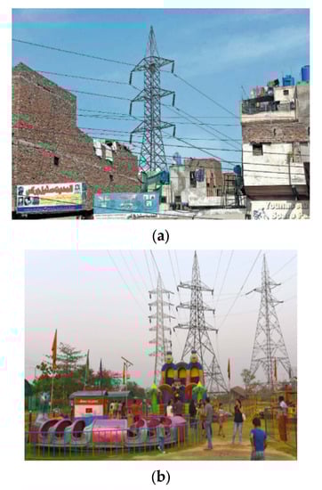
Figure 1.
(a) Infringement of right of way of transmission line due to infrastructure expansion and (b) housing buildings in children’s parks in [6,7].
Increasing load demand and changes in power structures force governments and utility companies to increase the capacity of existing transmission lines. It can be done either by increasing voltage, upgrading, or refurbishing. Increasing voltage and current on an existing line would cause the line conductors to overheat [8]. The result would be a loss of mechanical strength (annealing) of the conductor and excessive sag, which would cause an infringement of the statutory ground clearance [9]. Thermal equilibrium is a simple solution. When a conductor is heated by ohmic losses (I2R) and solar inputs, then cooling is accomplished by convection and radiation. Figure 2 illustrates the principle of “thermal equilibrium”.
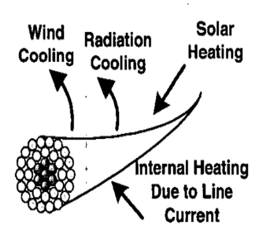
Figure 2.
Thermal equilibrium mechanism of overhead conductor [9].
Different solutions exist in the literature, such as reinsulation, reconductoring the line with a feverish temperature, low-sag conductor (HTLS), and an aluminium composite core cable (ACCC). At high temperatures and low sag, conductors can work better at higher temperatures than conventional conductors [10].
This review article is organised as follows: Section 2 consists of recent types of conductors used for uprating transmission lines, whereas Section 3 presents the advancements in composite cross-arm technology. Section 4 shows the benefits of tower structures with composite cross-arms. Finally, the conclusion is presented in Section 5.
2. Uprating Using HTLS Conductors
Conventional conductors, such as the ACSR conductor, usually work below 90 °C because the aluminium anneals are above this temperature. Special aluminium alloys have been developed to withstand feverish temperatures. These alloys do not lose mechanical strength at higher temperatures and maintain electrical conductivity [11]. The significant advantage of installing them instead of traditional ACSR conductors is that HTLS conductors can dissipate more heat while offering a lower coefficient of thermal expansion with better tensile strength [12]. Therefore, they can operate above 200 °C, while in some cases, the capacity of the current lines can be double that of conventional conductors operating below 100 °C [13]. These types of conductors are commercially available and are briefly described in Table 1 below.

Table 1.
Types of conductors [14].
In 2006, Larruskain et al. published work on power transmission capacity [14]. They increased the power transmission capacity of a transmission line by changing the ACSR conductor with an HTLS conductor of the same diameter. The HTLS conductor carries 2% more current than ACSR. So, the design of a new HTLS conductor may increase power by up to 200–500% [15].
3. Insulated Cross-Arm Technology
Most transmission line towers have steel cross-arms with steel lattice towers. Although rust will always be a problem, the primary cause of ending the life of a steel cross-arm is reconducting with heavy conductors due to capacitance issues [16]. Support tie-bars are likely to fail in cross-arms because of their flexibility and low construction [17,18].
Reconductoring with a heavier conductor due to capacity issues is the primary cause of a steel cross-arm failing before its expected lifespan. In addition, because the support tie-bars are flexible and not as strong as the cross-arm, they are more likely to break before the cross-arm [18]. Conductor failures are not usual on average, 2000 conductors can fail in the UK each year through storms or corrosion. The primary causes of HD copper conductor failure are typical overloads caused by snow/ice, tree problems, and collisions (causing arcing) in high winds.
Insulator cross-arms are replaced by insulator strings and steel lattice cross-arms, which are mechanically strong enough to withstand the compression and tension forces. It has advantages such as allowing the voltage to be operated without compromising the necessary clearance to the tower and ground. Moreover, there is no swing angle because the insulator is an insulator [19].
Installing insulated cross-arms on an EHV transmission based on this concept began early in the mid-1960s. Kimoto et al. (1971) [20] successfully developed and tested a prototype insulator cross-arm for a 345 kV EHV transmission line. They proposed two design configurations, the first having four solid-core porcelain post-insulator columns of the quadruple type and the other using two solid-core columns and two-disc insulator strings (twin-arm type). Figure 3 shows an example of the quadrant type and twin-arm type. With these designs, no extra insulators are needed because the conductors are fitted directly to the end of the bridge.
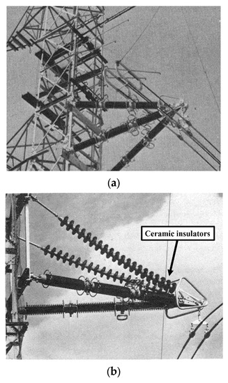
Figure 3.
(a) Quadruple-type and (b) twin-arm ceramic insulator [20].
In 1998, Barbarito et al. published their work [21]. One year later, his group was involved in a work published by Cecchetti and Noferi [22]. These two papers discuss the idea of the use of insulators as cross-arms, using either regular insulator strings or solid-core porcelain insulators to be fitted on a new bi-dimensional steel tower structure. These configurations made the whole tower structure physically compact [23]. The new 400 kV tower design is calculated to reduce the right-of-way and tower/foundation costs by up to 10%. However, an increase of up to 5% is seen in the price of insulator fittings. A double-circuit 132 kV compact line was successfully built in 1987 in Italy.
In 1998, a similar concept was implemented near Lausanne in Switzerland by Energy Ouest Suisse. The new compact tower design was bi-dimensional with two legs, as shown in Figure 4. It was the first paper to explain in detail the use of hollow-core silicone rubber composite insulators as insulated cross-arms.
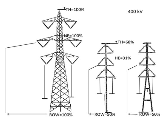
Figure 4.
Comparison between compact lines and new lines for 400 kV [21].
Similar technology introduced by, Barbarito et al [24] is currently being applied by the utility company Tenga National Behard (TNB) Malaysia and has been for several years. The transmission lines are erected using the full composite tower type, as shown in Figure 5. However, this technology could only be utilised in the newly developed areas that enable new lines to be built but not on the existing lines within the developing township area. We can see the technology applied to the power transmission lines erected along major routes in newly developed regions such as Cyberjaya, Selangor (Figure 5), Bandar Iskandar, Johor, and the DUKE highway in Kuala Lumpur. This technology is applied to the newly erected transmission lines in Cyberjaya. Although this technology enables only a small land area of occupation for the right-of-way route, it requires the complete removal of old tower structures on the existing lines (which is not viable for economic reasons). A solution for maintaining optimal current and voltage uprating the insulated cross-arms has potential benefits, such as allowing voltage uprating without compromising the needed clearances to the tower and ground. There is no swing angle because the cross-arm is an insulator [25]. Using novel technologies can achieve better mechanical and electrical performance at average operating temperatures.
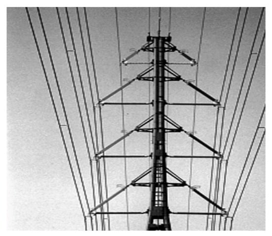
Figure 5.
Front view of the compact tower [24].
In 2000, Cheong published work on the Chengal wooden cross-arm [26], which discusses the idea of the Chengal wooden cross-arm because Chengal cross-arms can withstand the weight of power cables and insulators. Also discussed are the drawbacks of wooden cross-arms. The disadvantages of wooden cross-arms are that attacks by fungi, termites, lightning strikes, and woodpeckers increase decomposition and ageing. The decay stages are categorised first by the amount of moisture the wood can absorb and second by the density of the wood at various decay stages at specific moisture content. Wood was categorised into severely decayed, incipiently decayed, sound categories, and interior deterioration or defective areas extending up to 2 cm from the wood’s surface. Figure 6 shows the failure of the wooden cross-arm due to the lighting cross-arm [27]. A higher amount of leakage current flows through a wet wood sample than a dry wood sample. Moisture content lowers the other wooden structures’ electrical resistivity and the risk of leakage currents [28]. The ability of decayed wood to absorb more water than the condition or quality of the wood cross-arm [29].
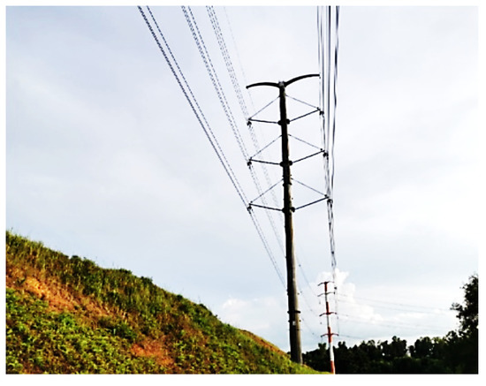
Figure 6.
An example of TNB’s compact composite tower line erected in Cyberjaya Selangor [25].
The history of the advancement in insulated cross-arm technology in the transmission lines is shown in Table 2.
Table 2.
History of insulated cross-arm Technology.
In 2008, Grzybowski discussed the concept of a fibre cross-arm in place of the wooden cross-arm to investigate the electrical performance of the fibreglass cross in transmission lines based on AC voltage and current flash over voltage under dry and wet conditions [30,49]. There have been different tests on different lengths of fibre cross-arms. The benefits as compared with wooden cross-arms are listed below. Figure 7 shows a steel tower with a fibre cross-arm.
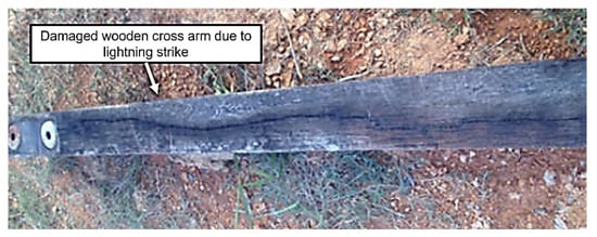
Figure 7.
Failure of the wooden cross-arm due to lighting [27].
- When all factors, particularly electrical performance, are considered, fibreglass cross-arms may be utilised instead of conventional cross-arms.
- Fibreglass cross-arms cannot be the only insulation. It must be used as secondary insulation, with an insulator as the primary insulation.
- For fibreglass cross-arms with porcelain insulators, the CFO voltage in dry and wet conditions is not significantly different. However, the AC flashover voltage in wet conditions is 50–60% lower than in dry conditions.
- The CFO voltages of fibreglass cross-arms are 30–40% higher than wood in dry conditions and 40–50% higher in wet conditions.
- The lightning impulse, wet flashover, wet withstand, and pollution withstand voltages of the FRP composite cross-arm increased by about 50%, 39.9%, 117%, and 30% compared with the iron cross-arm, respectively [50].
In 2009, Deng et al. published a paper on insulated cross-arms and towers made of composite material [31]. As a result, lightning protection and anti-pollution flashover for transmission lines have been improved; the transmission corridor width has been reduced; and land resources and total operation and maintenance costs have been saved. Compared with standard metal towers, composite material towers have unique advantages [32]. However, the present material does have some weak points or defects, such as large deflection, inadequate resistance to electrical erosion and electric arc, and weak hydrophobicity. The length of the cross-arm of fibreglass and wood increases, and the CFO voltage per unit length decreases [51]. This paper reports that a 110 kV tower made of composite material was successfully built for the first time in China in 2009. Figure 8 shows a 110 kV tower of combined single-pole double-circuit material and a complete composite double-pole double-circuit material. The voltage of the power protection section changes from 10% to 50% under clear conditions to icy conditions because of the ice-covered insulator surface [52].
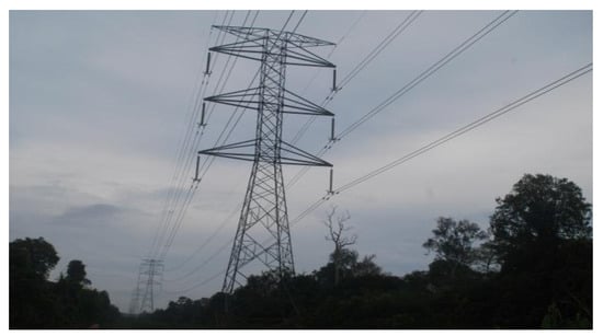
Figure 8.
Fibre cross-arms on steel tower [49].
In 2010, Rowland et al. invented a new insulated cross-patent under PCT [53]. The inventors realized that an insulated cross-arm could replace the convention tower’s conductive cross-arm. The design of the new insulated cross-arm is shown in Figure 9 below.
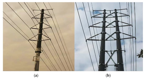
Figure 9.
(a) 110 kV tower of combined composite single-pole double-circuit material and (b) 110 kV tower of complete composite double-pole double-circuit material [31].
- The benefits of the cross-arms are below:
- Resistance against buckling.
- Lightweight.
- Eliminate conductor swing toward the tower.
- Used for high-voltage networks.
In 2010, Rowland et al. published work on increasing power capacity [33]. Using composite cross-arms with the new conductor overhead line tower shows a clear improvement in power capacity. The result of this paper is from a 275 kV tower in the UK.
The benefits of the composite cross arm are:
- It allows voltage uprating to 400 kV without violating tower and ground clearances.
- It allows the use of high-temperature HTLS conductors.
- This structure’s advantage is that there is no swing angle.
- Figure 10 shows the minimum clearance at 0°.
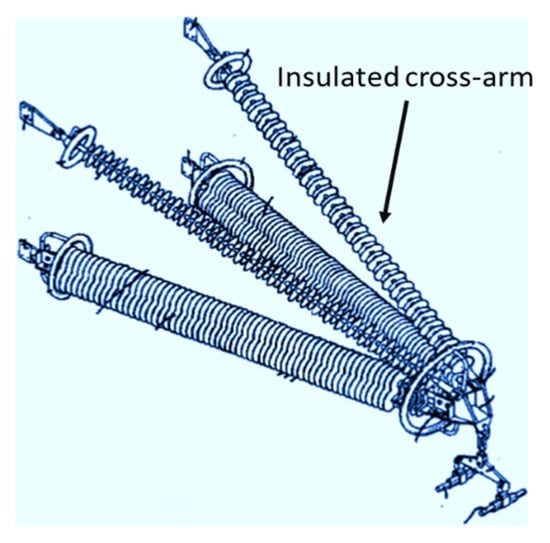 Figure 10. Insulated cross-patent under PCT [53].
In 2012, Selvaraj et al. published work on FRP pultruded profiles made of composite cross-arms [34,54]. In this case, FRP pultruded profiles are used [55]. The mechanical performance of the composite cross-arm was evaluated using experimental testing, an analytical solution, and a finite element simulation. A mechanical test on a composite cross-arm under simultaneous loads, applied in three perpendicular directions, is carried out, and the maximum deflection at the tip of the cross-arm is measured. The finite element model is developed to plot the leading stressed areas in good correlation, i.e., the error percentage is about 9–11% between theoretical and experimental results. A considerable reduction in transmission corridor is achieved by using the composite cross-arm in place of a steel cross-arm with ceramic insulators [56]. The systematics of the test setup and its photograph are shown in Figure 11.
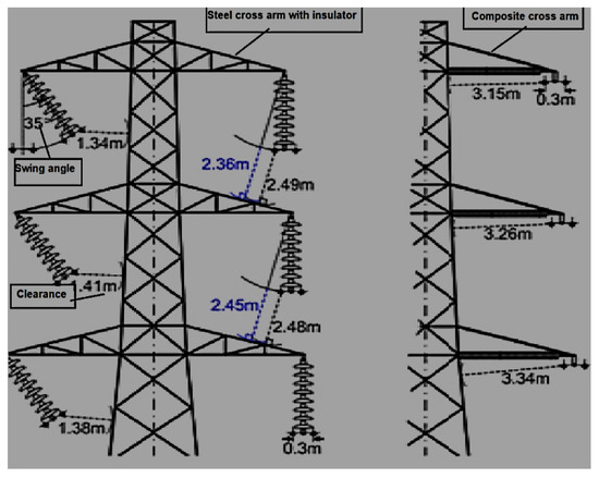
Figure 11.
Clearances of 275 kV L3-type tower with regular suspension and modified composite cross-arm [33].
In 2012, Peesapati et al. published their work [35]. In these papers, composite insulators were replaced on the existing high-voltage insulator and the cross-arm of the transmission line tower. The analysis of the composite cross-arm justified it as an alternative solution. Moreover, the study is based on the scene when the composite arm is polluted or wet, which puts it under electrical stress [57]. Therefore, it is key to validating the design parameters widely accepted by electrical utilities. Figure 12 shows the full-scale model of the composite cross-arm.
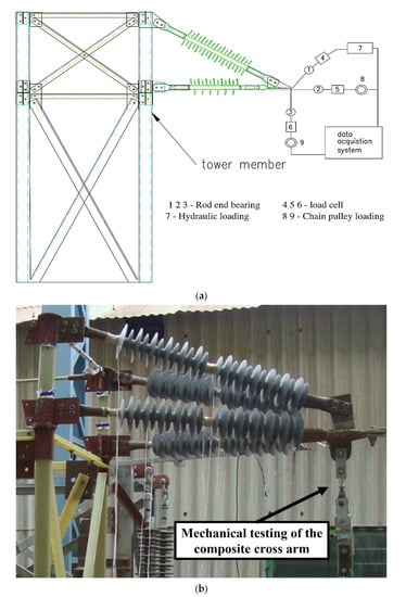
Figure 12.
(a) The systematics of the test setup and (b) photograph of the composite cross-arm under mechanical testing [34].
In 2013, Zachariades published their work on the behaviour of the cross-arm [36]. In this case, the electrical behaviour of the cross-arm is observed by monitoring the leakage current in real time. Due to the large cross-section area, the base leakage current profile of compression of the cross-arm is higher, and its response to changes in the weather is milder, with slight fluctuations. Extra work is being conducted to separate the effects of capacitive coupling and isolate the part of the leakage current caused by resistance. This paper also reports that the two insulating cross-arms of 231 kV were successfully installed near the coast of Scotland [58]. The two insulating cross-arms of 231 kV on each side are on the west and the other on the south, as shown in Figure 13.
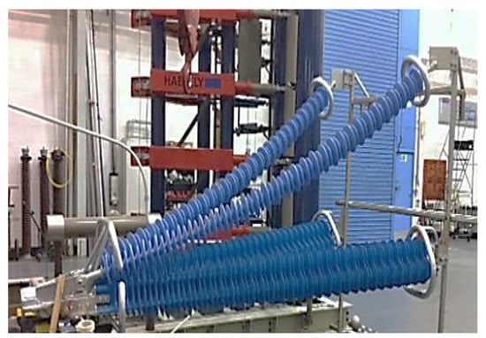
Figure 13.
Full-scale prototype cross-arm [35].
In 2014, Yang et al. published a similar work on 750 kV [37]. In this work, they obtained the computational results of the potential and electric field distribution for composite cross-arms [59] in structural optimisation. The final design is made to omit the suspension insulator string, increase the length of post insulators, and configure proper grading and shielding rings. This paper discusses the first composite cross-arm successfully installed on a 750 kV AC transmission line tower in China, shown in Figure 14 [60].
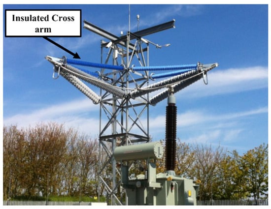
Figure 14.
Two insulating cross-arms of 231 kV [36].
In 2015, Wang et al. published work on a 750 kV cross-arm [38]. The electric field distribution is calculated at the ultrahigh voltage of a 750 kV cross-arm with a silicone rubber sheath under light impulse voltage [61]. Each composite cross-arm insulator has similar voltages. As a result, fittings have similar electric field distributions. The maximum electric field strength difference is 0.6% to 2.9%. The impulse voltage tests [62] of the composite cross-arms are shown in Figure 15.
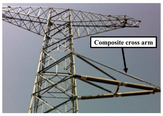
Figure 15.
Picture of 750 kV composite cross-arms [37].
In 2017, Zhang et al. published work on a compact type of composite cross in tower design [39]. They analysed the cross-arm’s structural composition and connection mode by tightening the vibration and tower head structures of the cup tower, cathead tower, and upper-shape tower using composite cross-arms and made technical and economic comparisons among the three towers. As a result, the width of the corridor in the cup tower, the upper-shape tower, and the cathead tower were reduced by 3.2 m, 3 m, and 3.6 m, respectively. It solved the problem of making the corridor wider when the conventional tower was used. Technical and economic comparisons show that the width of the corridors in the three types of towers is reduced by 5.9 m, 5.8 m, and 3.2 m, respectively, and that the cost ratio is 116%, 120%, and 101%, respectively, compared with the cost ratio in conventional cup towers. After looking at everything, it was decided that the compact-type [63,64] cup tower with a composite cross-arm was the best in terms of technology and cost. The results of this paper are taken from the Grid Henan Economic Research Institute in Henan, China.
In 2017, Bozkurt et al. published a paper on the economic analysis of transmission line towers [40]. As a result, right of way (ROW) decreases in 400 kV power transmission line towers using composite cross-arm insulators (four pultruded structure components) instead of pin-type and long-rod insulators, as shown in Figure 16. Moreover, insulator costs are reduced by using composite cross-arm insulators [65] instead of glass and porcelain pin-type insulators. In addition, as the span between towers increases, using composite cross-arm insulators instead of long-rod insulators is more economical. It saves energy during the time they are used.
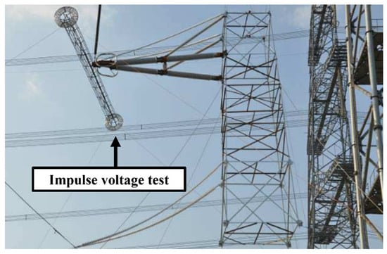
Figure 16.
Impulse voltage test for electric field computation [38].
In 2018, Syamsir et al. published a paper on the mechanical strength of fibre-reinforced polymers [41]. In this work, composites as an alternative to cross-arm structures are replaced by conventional cross-arms due to their simple production, light weight, mouldability, high-quality surface finishes, and superior mechanical qualities [42]. Creep is essential for an element’s maximum load-bearing capacity. Extreme creep deformation may damage or collapse a structure. After 6 and 14 months, GFRP creep lowered young’s modulus by 20%. The creep behaviour of the GFRP pultruded flexural component shows shear stiffness after 50 years with a 22% to 43% due to shear deformation instead of bending counterpart. Creep research on GFRP girders [66] shows an increase in immediate deflection of up to 40% after five months, demonstrating GFRP’s promise in structural sectors. The results of this paper were taken from a 115 kV transmission line tower under the TNB transmission line division in Malaysia.
In 2019, Zhongguo et al. published a paper on a full-scale three-dimensional simulation model of an AC 500 kV transposition tower [43,67]. In 2015, certain composite insulators from Dongguan Power Supply Bureau’s 500 kV transposition towers were punctured, as shown in Figure 17. The electric field distribution was computed with the finite element method. As a result, the electric field in the transposition tower is more severely distorted, and the composite insulators are vulnerable. The electric field intensity on both ends of the same insulator is higher than that in the middle; that is to say, the distribution of electric fields is non-uniform along the composite insulator. The high-voltage end housing has the highest surface electric field intensity. The non-uniform electric field distributions on the surface of the insulator are caused by their different configurations of conductors, which is also why electric field distributions are different between transposition and regular towers. Changing the grading ring design or installing disc suspension porcelain insulators on the composite insulator’s high-voltage end helps balance the insulator’s electric field distribution on the transposition tower. The results of this paper were taken from a report on a double-circuit 500 kV AC transmission line tower in China.
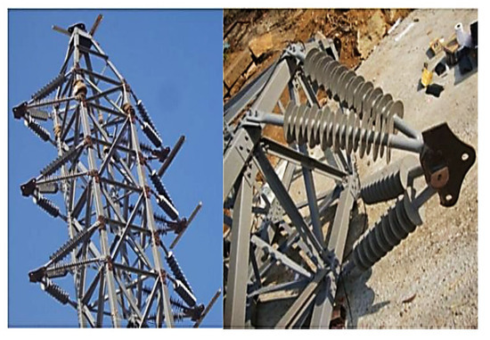
Figure 17.
Composite cross-arm insulators (four pultruded structure components) [40].
In 2020, Asyraf et al. published work on green composite technology [43]. The cross-arm components are made from natural fibre with a reinforced biopolymer composite. It is a green composite material. Many researchers and industries are paying attention to this due to its excellent mechanical ability and the material’s green technology. Given that green composite cross- arms are novel in this area, some features, including creep, fatigue, and quasistatic mechanical performance, need to be found and assessed. It is thus essential to research more advanced processing procedures for natural fibre-reinforced biopolymer composite cross-arms to replace the traditional cross-arms in transmission towers. The green composite has the potential to substitute for FRP, PGFRP, and the wooden cross-arm shown in Figure 18.
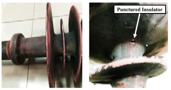
Figure 18.
Punctured insulator [67].
In 2021, Bao et al. published a paper on the model of a quadruple-circuit 500 kV transmission line [45]. The simulation and calculation analysis of lightning were completed with a steel tower. The research shows that the tolerance lighting level of CMCA towers is superior to conventional steel towers. The lightning withstand level of single-circuit flashover is 45% higher than that of a steel tower, and the minimum shielding failure lightning withstand level is 47% higher than that of the steel tower. The quadruple-circuit 500 kV transmission line CMCA tower is shown in Figure 19. The CMCA tower is more impacted by the grounding resistance change than the steel tower. The electrical withstand levels of the CMCA tower and steel tower decreased by 41.7% and 32.6%, respectively, as the ground resistivity increased from 5 to 20 Ω.
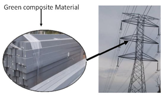
Figure 19.
Potential application of green composite in cross-arm beams [43].
In 2021, Amir, A. et al. published a review on composite cross-arms [68]. The honeycomb-filled structure will still be a hotspot in engineering applications. The general honeycomb-filled concept is preferred over tandem and embedded honeycombs due to its easy manufacturing and straightforward configuration [44,69]. In addition to that, the honeycomb-filled structure allows an increase in strength, energy absorption, flexural behaviour, load-carrying capacity, and creep response shown in Figure 20. However, previous research shows that sandwich panels and beams with honeycomb-filled structures outperform the hollow system depicted in Figure 21 [46]. There is still limited information on the performance of pultruded glass fibre-reinforced polymer composite cross-arm (PGFRPC) honeycomb-filled structures. Several studies are needed to be identified and evaluated, such as:
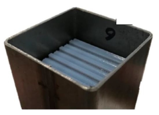
Figure 20.
Honeycomb-filled structure [68].
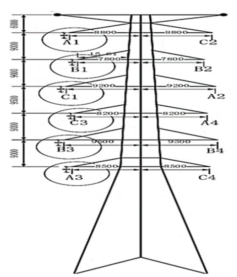
Figure 21.
Structure of CMCA [45].
- Improvement of the existing manufacturing process of composite structures to have an economical and highly efficient manufacturing method for honeycomb-filled PGFRPC cross-arm beams.
- Furthermore, an actual-scale study of the honeycomb-filled PGFRPC cross-arm on related flexural characteristics, creep responses, load-carrying capacity, and failure mode behaviour.
- They match honeycomb-core properties with PGFRPC beams due to deformation mode behaviour.
In 2021, Da Silva et al. published a paper on a Y-shaped tower [47]. A new Y-shaped composite pylon for a 2 × 400 kV overhead transmission line tower is proposed. Low-density polyethene material (LDPE) is used to fill in the cross-arm. In addition, the clamp structure was redesigned. The LPDE material prevents the electric field intensity in the cross-arm [70,71]. Furthermore, the conductor enclosure is removed, and the height of the clamp is reduced. A fully composite pylon without shield wires was the first alternative to using surge arresters to protect the pylon from electrical shocks [72].
- The conductors are attached to the unibody cross-arm using special conductor clamps. The distance between phases on the pylon is the same as the arcing distances.
- The two shield wires are fixed to the ends of the unibody cross-arm using clamps. As a result, the shielding angle is negative for the pylon.
- The pylon requires a smaller transmission corridor than its counterparts. With a compact configuration, the pylon can fit more easily into the landscape and have less visual impact on the surrounding residents.
A Y-shaped composite pylon overhead line tower with a 30° tilt angle of the unibody cross-arm is shown in Figure 22, which indicates a unique visual form [73].

Figure 22.
Y-shaped composite pylon overhead line tower [71].
In 2022, Asyraf et al. published a review on composite cross-arms [48]. In this paper, PGFRPC is replaced by a filament-wound polymer composite as the cross-arm structure in the lattice transmission tower. The materials used in filament winding are polyester resins [74]. The filament-wound composites improve stiffness, strength, and surface finish. The filament winding process makes it easy to install a cross-arm with a honeycomb-like core structure for better flexure properties and resistance to micro-cracking and flaking, shown in Figure 23.
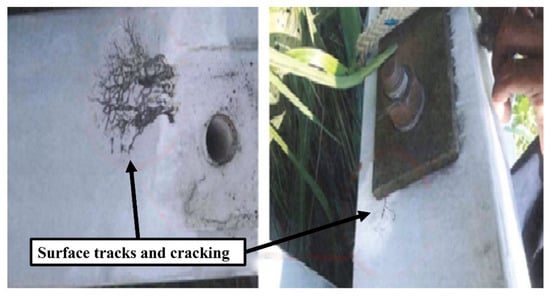
Figure 23.
Surface tracking and cracks on the composite cross [48].
4. Tower Design
Accurate modelling of transmission line towers is essential for insulation design. When a lightning discharge hits ground wires or towers, the response to the incident may be with an associated short-circuit fault. Back flashovers consist of arcs along the insulator strings of one or more phase conductors due to a rapid increase in tower voltage concerning the phase conductor voltages [75]. Back flashover events can occur due to transient ground potential surges associated with lightning currents flowing along the tower [76,77,78].
The history of the development of tower structures with composite cross-arm technology in the overhead line is shown in Table 3.
Table 3.
History of Tower Design.
In 2010, Dai et al. published a paper on tubular composite towers [79]. In this paper, tubular composite towers are made of polyurethane resin. The composite tower body is shown in Figure 24, and insulation is used to enhance the phase-to-ground and phase-to-phase insulation strengths for transmission line towers to increase the lightning protection capacities. Test and calculation evaluation results of lightning performances, lightning impulse insulation strength, and lightning trip rate of composite towers using the design with ground-down lead suspended on the inner side may be increased by 28% and decreased by 54% compared with those using the ground-down lead mode along the tower, respectively. This paper reports that 132 kV single-circuit overhead transmission lines have been successfully built in Canada.
In 2013, Liu published a paper on three types of towers [80]. This paper analyses three types of towers: d-type, e-type, and vertical, as shown in Figure 25. The power frequency electric field is the most crucial factor determining how the electromagnetic environment is affected by a 500/220 kV mixed-voltage quadruple-circuit transmission line [88,89]. Among the several types of transmission towers, the d-type tower has the most advantages of the three different towers.
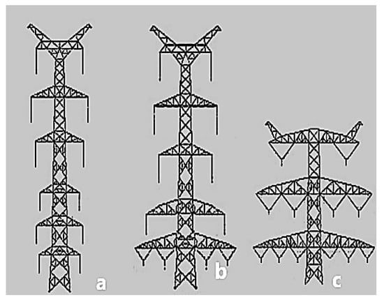
Figure 25.
Typical tower 500/220 kV mixed-voltage quadruple-circuit [80], (a) vertical tower, (b) d-type tower, and (c) e-type [80].

Figure 24.
Experimental setup for testing [90].
Figure 24.
Experimental setup for testing [90].

However, the e-type tower has the lowest construction costs and the best performance when preventing lightning strikes compared with the d-type tower. However, the third cross-arm length of the e-type tower is so long that it occupies the entire width of the corridor and works against the live working and the maintenance of the upper cross-arm lines. However, the vertical tower provides the most remarkable ease of maintenance. Shown in Figure 25.
In 2013, Zhang et al. published their work on the ZB1 cup-type steel tubular tower [81]. The entire full-scale tower uses steel tubes and forging flanges, except the tower foot. The full-scale test verified the reliability of the Q345 steel tube and forging flange in the application of the cup-type power transmission steel tower. This first tower of 1000 kV was successfully built in the heavy icing area of Beijing, China in 2012. A full-scale test of the ZB1 cup-type tower is shown in Figure 26.
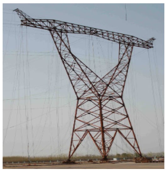
Figure 26.
Full-scale testing the ZB1 cup-type tower [81].
In 2013, Ghugal et al. published a paper analysing a three-legged transmission line tower [82]. In this paper, a comparison between three-legged towers with an angle section as compared with three-legged towers with a tube section is made [91]. The axial forces increased in all members in the three-legged tower with angle sections compared with the three-legged tower with tube sections during all components. In a triangular tower with a tube section, deflection increases in normal conditions compared with angle sections but remain within permissible limits. A saving in steel weight of 20.6% resulted when using a three-legged tower tube section compared with an angle section. This paper reports that 400 kV double-circuit overhead transmission lines were successfully designed in India.
In 2014, Kulkarni et al. published a paper on the FRP tower [83]. This paper’s comparison between steel and FRP composite towers is shown in Figure 27. The tower height achieved 17% compared with the steel tower. The new tower meets some mechanical requirements that a steel tower be feasible. The composite cross-arm can be used for uprating the existing overhead transmission line because of its light weight. This paper reports that an FRP composite material overhead transmission line tower was successfully designed for the first time in India in 2012.
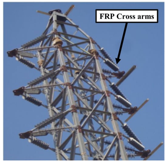
Figure 27.
Photo of FRP cross-arm on FRP tower body [83].
In 2014, Zhuang et al. published a paper on the lighting protection of JG-type towers [84]. This study employs various methods to safeguard JG-type tower lighting. The most frequent reason for 500 kV transmission line trips is lightning flashover. Lightning shielding failure flashovers were to blame for most trips. In recent years, there have been four lightning trips. The lightning shielding failure flashover of the transmission line with the JG-type tower is relatively high [92]. To decrease the flashover rate by more than 50%, installing a tower top-side rod for the JG-type tower in the plains and two arresters suspended on the cross-arms of the middle phase and outside corner is recommended for the JG-type tower in the mountains. Figure 28 shows the structure of the JG-type tower.
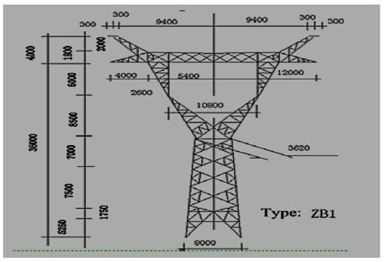
Figure 28.
Structure of JG-type tower [84].
In 2018, Chen et al. published a paper on cross-arm towers [85]. This paper discusses electric field strengths on transmission lines’ three and four cross-arm towers. The average maximum electric field strengths of transmission lines’ six and four cross-arm towers of transmission lines were 14.33–15.70 kV/cm and 12.29–15.90 kV/cm, respectively. By comparing the corona loss and resistance loss of transmission lines under the optimal and the worst phase sequence arrangements in the project involving 750 kV four-circuit transmission lines on the same tower, it was found that the annual average CL was 25% to 47% of the resistance loss [93,94]. Moreover, the maximum corona loss from these transmission lines was between 107% and 215% of the resistance loss.
In 2020, Xing et al. proposed an aluminium alloy tower built of steel and galvanised it to prevent corrosion [86]. This paper also investigates the use of high-strength aluminium alloy to address the problems of atmospheric corrosion of transmission towers in coastal and heavy-industry pollution areas, sand erosion of transmission tower zinc coatings in vital wind sand areas, and transportation difficulties in rugged mountain areas. High-strength aluminium alloy transmission towers have many advantages compared with standard steel towers.
- 5.
- This high-strength aluminium alloy tower has good corrosion resistance and can avoid galvanic pollution through routine anti-corrosion maintenance.
- 6.
- The density of high-strength materials is 1/3 that of steel, reducing the construction difficulty and cost.
- 7.
- Under the same design conditions, the weight of a high-strength aluminium alloy tower is 10% lower than that of an iron tower.
- 8.
- High-strength aluminium alloy towers are suitable for transmission lines in coastal areas, industrial pollution areas, and rugged mountainous areas.
In 2021, Zhang et al. published a paper on the analysis of composite towers [87]. This paper analyses the variation law of unbalanced stress designs for an unstable stress-adjusting device and verifies the application effect of the device [95]. The research shows that the unbalanced tension of the composite tower line increases significantly due to the reduction in the length of the suspension string [96]. Therefore, in 2021 in China, a device designed can efficiently minimise imbalanced stress at the suspension point of the composite tower, which is necessary to assure the line’s safety. Furthermore, the spring stiffness within the device affects the device’s adjustment effect. The lower the spring stiffness, the greater the adjustment effect but the higher the hanging point stroke. The design diagram of the new sliding point device is shown in Figure 29.
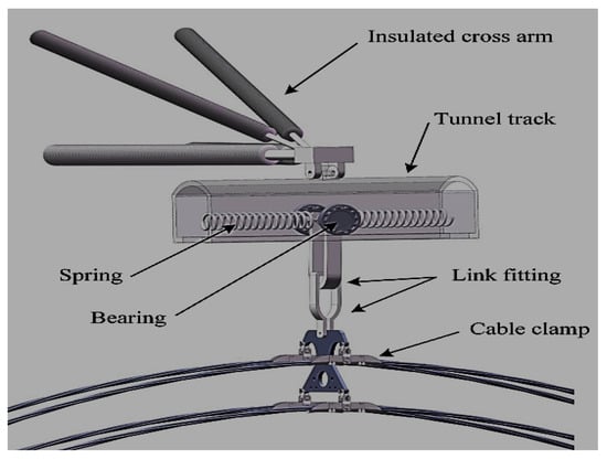
Figure 29.
Design diagram of new sliding point device [97].
5. Future Research Directions
Machine learning (ML) and artificial intelligence (AI) are emerging access tools. High-voltage tests and modelling accuracy can be increased using ML and AI. More in-depth research on composite materials can be conducted, such as running additional salt-fog tests on the sample profiles to evaluate how well they function in terms of current and voltage data. Additional research on the composite samples should also be based on the appropriate tests outlined in the standards.
The major research interest for utility supply companies is retrofitting a new cross-arm to an old tower. Researchers will investigate retrofitting to determine its limits and how to prevent the conductor bundle from falling. During the transition, each conductor might be temporarily attached to the neighbouring cross-arm. In this situation, the tower and cross-arms strength must be analysed.
Another research aspect is that when cross-arm design changes the conductor/cross-arm system’s dynamics may change. It may affect wind-induced conductor motion and cross-arm fatigue performance. Finite element modelling and testing must determine whether the new cross-arms improve conductor movement dampening.
6. Conclusions
The steel tower has been used for high-voltage transmission lines for about 50 years. This aging grid infrastructure requires increased power capacity to cope with increasing load demand. Over the years, rapid growth has resulted in the fast conversion of many rural areas to urban to meet the needs of the growing local population. Continuously increasing load demand and changes in power structures force governments and utility companies to increase the capacity of existing transmission. It is done either by increasing voltage, upgrading, or refurbishing. Increasing voltage and current on an existing line would cause the line conductors to overheat. The result would be a loss of mechanical strength (annealing) of the conductor and excessive sag, which would cause an infringement of the statutory ground clearance. Thermal equilibrium is a simple solution. Different solutions exist in the literature, such as reinsulation, reconductoring the line with a feverish temperature, low-sag conductor (HTLS), and an aluminium composite core cable (ACCC). Low-sag conductors can work better at feverish temperatures than conventional conductors at higher temperatures.
Most transmission line towers have steel cross-arms with steel lattice towers. However, failures in steelwork have been reported due to blizzard conditions and faulty conductors. Reconductoring with a heavier conductor due to capacity issues is the primary cause of a steel cross-arm failing before its expected lifespan. Installing insulated cross-arms on an EHV transmission line is the solution for optimal current and voltage uprating. The insulated cross-arms have potential benefits, such as allowing voltage uprating without compromising the needed clearances to the tower and ground. In addition, there is no swing angle because the cross-arm is an insulator. As a result, reconductoring is the only technique to boost its power transmission capability.
Chengal cross-arms can withstand the weight of power cables and insulators. Natural wood defects are due to fungi, termites, and woodpeckers, which speed up their decomposition and ageing. So, the transmission tower’s cross-arm uses pultruded glass fibre-reinforced unsaturated polyester composites. However, the problems of using pultruded composites in cross-arm are that durability and lifespan issues may arise. Cyclic wind loading causes tiny cracks in the cross-arms of the PGFRPC, which could cause the structure to fail. Extreme heat and moisture cause hydrothermal. A filament-wound polymer composite will replace PGFRPC as the cross-arm structure in the lattice transmission tower. The filament-wound composites improve stiffness, strength, and surface finish. The filament winding process makes it easy to install a cross-arm with a honeycomb-like core structure for better flexure properties and resistance to micro-cracking and flaking.
The unbalanced tension of the composite tower line increases significantly due to the reduction in the length of the suspension string. The device’s design can efficiently minimise imbalanced stress at the suspension point of the composite tower, which is necessary to assure the line’s safety.
More in-depth research on composite materials should be carried out, such as running additional salt-fog tests on the sample profiles to evaluate how well they function in terms of current and voltage data. Additional research on the composite samples should also be based on the appropriate tests outlined in the standards.
Retrofitting a new cross-arm to an old tower must be investigated to determine its limits and how to prevent the conductor bundle from falling. During the transition, each conductor might be temporarily attached to the neighbouring cross-arm. In this situation, the tower and cross-arms strength must be analysed.
Due to cross-arm design changes, the conductor/cross-arm system’s dynamics may change. It may affect wind-induced conductor motion and cross-arm fatigue performance. Finite element modelling and testing must determine whether the new cross-arms improve conductor movement dampening.
Author Contributions
Conceptualisation M.A. and M.N.R.B.B.; validation Z.Z. and I.U.; resources L.H.M., N.A.M.J., and M.F.M.Y.; writing—original draft preparation M.S.K. and R.A.R.; writing—review and editing and funding acquisitions M.A. and M.N.R.B.B. All authors have read and agreed to the published version of the manuscript.
Funding
This research was supported by The Ministry of Higher Education (MOHE) Malaysia through the Fundamental Research Grant Scheme (FRGS/1/2021/TKO/UTHM/02/30).
Data Availability Statement
Not applicable.
Conflicts of Interest
The authors have no conflict of interest.
References
- Littler, D.J.; Davies, E.J.; Johnson, H.E. EHV Transmission, 3rd ed.; Elsevier: Amsterdam, The Netherlands, 1991; Volume K. [Google Scholar]
- Baharom, M. Composite Cross-Arms for Overhead Transmission. Ph.D. Thesis, School of Electrical Engineering, The University of Manchestor, Manchestor, UK, 2009. [Google Scholar]
- Sulaiman, S.S.; Khali, R.; Aminudin, N.H. Legal Issues and Challenges in Regulating the Rights to Wayleave in Malaysia. Int. J. Eng. Technol. 2018, 7, 174–177. [Google Scholar] [CrossRef]
- Raj, A.A.; Lee, C.P.; Sidek, M.F. Protection against EMF at Transmission Line and Tower. In Proceedings of the PECon IEEE International Conference on Power and Energy, Virtual, 7–8 December 2020; pp. 376–381. [Google Scholar] [CrossRef]
- Das, H.; Gogoi, K.; Chatterjee, S. Analysis of the effect of electric field due to High Voltage Transmission lines on humans. In Proceedings of the 2015 1st Conference on Power, Dielectric and Energy Management at NERIST (ICPDEN), Itanagar, India, 10–11 January 2015; pp. 1–4. [Google Scholar] [CrossRef]
- Lesco Tells Nepra Shifting Transmission Lines Impossible—Pakistan—DAWN.COM. Available online: https://www.dawn.com/news/1678971 (accessed on 11 August 2022).
- High-Voltage Cables above Indirapuram Parks Pose Risk for Visitors. Available online: https://timesofindia.indiatimes.com/blogs/no-filter/high-tension-lines-above-indirapuram-parks-pose-risk-for-visitors/ (accessed on 15 August 2022).
- Ferguson, J.; Gibbon, R. Overhead transmission lines—Refurbishment and developments. Power Eng. 1994, 8, 109–118. [Google Scholar] [CrossRef]
- Daconti, J.; Lawry, D. Increasing power transfer capability of existing transmission lines. In Proceedings of the IEEE Power Engineering Society Transmission and Distribution Conference, New Orleans, LA, USA, 25–28 April 2003. [Google Scholar] [CrossRef]
- Ntuli, M.; Xezile, R.; Mbuli, N.; Pretorius, J.H.C.; Motsoeneng, L. Increasing the capacity of transmission lines via current uprating: An updated review of benefits, considerations and developments. In Proceedings of the 2016 Australasian Universities Power Engineering Conference, AUPEC, Brisbane, Australia, 25–28 September 2016. [Google Scholar] [CrossRef]
- Mateescu, E.; Marginean, D.; Florea, G.; Gal, S.I.A.; Matea, C. Reconductoring using HTLS conductors. Case study for a 220 kV double circuit transmission LINE in Romania. In Proceedings of the IEEE International Conference on Transmission and Distri-bution Construction and Live Line Maintenance, ESMO, Providence, RI, USA, 16–19 May 2011; pp. 1–7. [Google Scholar] [CrossRef]
- Bedialauneta, M.; Fernandez, E.; Albizu, I.; Mazon, A. Comparison of the theoretical and the actual behavior of an overhead conductor in operation. In Proceedings of the IEEE Power and Energy Society Conference and Exposition in Africa: Intelligent Grid Integration of Renewable Energy Resources (PowerAfrica), Johannesburg, South Africa, 9–13 July 2012. [Google Scholar] [CrossRef]
- Riba, J.-R.; Bogarra, S.; Gómez-Pau, Á.; Moreno-Eguilaz, M. Uprating of transmission lines by means of HTLS conductors for a sustainable growth: Challenges, opportunities, and research needs. Renew. Sustain. Energy Rev. 2020, 134, 110334. [Google Scholar] [CrossRef]
- Larruskain, D.; Zamora, I.; Abarrategui, O.; Iraolagoitia, A.; Gutiérrez, M.; Loroño, E.; De La Bodega, F. Power transmission capacity upgrade for overhead lines. Renew. Energy Power Qual. J. 2006, 1, 221–227. [Google Scholar] [CrossRef]
- Mazon, A.; Zamora, I.; Eguía, P.; Torres, E.; Miguelez, S.; Medina, R.; Saenz, J. Analysis of Traditional Suspension Strings with GTACSR Conductors. IEEE Trans. Power Deliv. 2004, 19, 1198–1203. [Google Scholar] [CrossRef]
- Rao, N.P.; Mohan, S.J.; Lakshmanan, N. A study on failure of cross arms in transmission line towers during prototype testing. Int. J. Struct. Stab. Dyn. 2005, 5, 435–455. [Google Scholar] [CrossRef]
- Rao, N.P.; Knight, G.S.; Mohan, S.; Lakshmanan, N. Studies on failure of transmission line towers in testing. Eng. Struct. 2012, 35, 55–70. [Google Scholar] [CrossRef]
- Papailiou, K. Composite insulators are gaining ground-25 years of Swiss experience. In Proceedings of the IEEE Power Engineering Society Transmission and Distribution Conference, New Orleans, LA, USA, 11–16 April 1999; Volume 2, pp. 827–833. [Google Scholar] [CrossRef]
- I Performance: Combined Load Limitations of Composite Line Posts. 2022. Available online: https://www.inmr.com/combined-load-limitations-of-composite-line-posts (accessed on 18 March 2022).
- Kimoto, I.; Kito, K.; Ueno, K. Insulator Crossarms for 345-KV EHV Transmission Line. IEEE Trans. Power Appar. Syst. 1971, PAS-90, 756–767. [Google Scholar] [CrossRef]
- Barbarito, M.; Clerici, A.; Paris, L.; Pelacchi, P. New type of compact line for urban and suburban areas. In Proceedings of the 1989 International Conference on Overhead Line Design and Construction: Theory and Practice, London, UK, 28–30 November 1988; Volume 297, pp. 40–45. [Google Scholar]
- Cecchett, E.; Noferi, P.L.; Barbarit, M.; Cleric, A.; Pelacch, P.; Sadelmi, S. Compact Lines for Urban Areas: A New Solution. Dev. Built Environ. 2016, 15, 1–23. [Google Scholar]
- Gençoğlu, M.T. The Comparison of Ceramic and Non-Ceramic Insulators. e-J. New World Sci. Acad. 2007, 2, 245. [Google Scholar]
- Burkhardt, B.; Baettig, G.; Terrasi, G.P.; Papailiou, K.O.; Schmuck, F. New Solutions With Composite Insulators And Composite Structures For Compact Lines. In Proceedings of the 17th International Conference on Electricity Distribution, Barcelona, Spain, 12–15 May 2003; pp. 12–15. [Google Scholar]
- Albizu, I.; Mazon, A.J.; Zamora, I. Methods for increasing the rating of overhead lines. In Proceedings of the IEEE Russia Power Tech, St. Petersburg, Russia, 27 January 2005; pp. 1–6. [Google Scholar] [CrossRef]
- Khalid, K.; Hamami, M.; Cheong, N.K.; Fuad, S. Microwave reflection sensor for determination of decay in wooden cross-arms. In Proceedings of the IEEE International Conference on Properties and Applications of Dielectric Materials, Xi’an, China, 6 August 2002; pp. 595–598. [Google Scholar] [CrossRef]
- Rawi, I.M.; Rahman, M.S.A.; Kadir, M.Z.A.A.; Izadi, M. Wood and fiberglass crossarm performance against lightning strikes on transmission towers. In Proceedings of the IPST—International Conference on Power Systems Transients, Seoul, Korea, 26–29 June 2017. [Google Scholar]
- Wong, K.L.; Pathak, S.; Yu, X.H. Leakage current flow through wooden pole structures of varying age on overhead distribution system. In Proceedings of the 2007 Australasian Universities Power Engineering Conference, Perth, WA, Australia, 9–12 December 2007; pp. 1–6. [Google Scholar] [CrossRef]
- Khalida, K.; Sahrjb, M.H.; Keonga, N.K.; Fuadc, S.A. Microwave dielectric properties of wooden cross-arms. In Proceedings of the SPIE’s International Symposium on Optical Science, Engineering, and Instrumentation, Denver, CO, USA, 18–23 July 1999; Volume 3752. [Google Scholar]
- Grzybowski, S. Electrical performance of 115 kV transmission lines fiberglass crossarms aged in field. In Proceedings of the 5th International Conference on Properties and Applications of Dielectric Materials, Seoul, Korea, 25–30 May 1997; Volume 2, pp. 774–777.
- Li, H.-M.; Deng, S.-C.; Wei, Q.-H.; Wu, Y.-N.; Xiang, Q.-Q. Research on composite material towers used in 110 kV overhead transmission lines. In Proceedings of the 2010 International Conference on High Voltage Engineering and Application, ICHVE, New Orleans, LA, USA, 11–14 October 2010; pp. 572–575. [Google Scholar] [CrossRef]
- Chandrashekhara, K.; Watkins, S.E.; Nanni, A.; Kumar, P. Design and technologies for a smart composite bridge. In Proceedings of the 2004 IEEE Intelligent Transportation Systems Conference, Washington, DC, USA, 3–6 October 2004. [Google Scholar] [CrossRef]
- Kopsidas, K.; Rowland, S.M.; Baharom, M.N.R.; Cotton, I. Power transfer capacity improvements of existing overhead line systems. In Proceedings of the 2010 IEEE International Symposium on Electrical Insulation, San Diego, CA, USA, 6–9 June 2010; pp. 1–5. [Google Scholar] [CrossRef]
- Selvaraj, M.; Kulkarni, S.; Babu, R.R. Analysis and experimental testing of a built-up composite cross arm in a transmission line tower for mechanical performance. Compos. Struct. 2013, 96, 1–7. [Google Scholar] [CrossRef]
- Peesapati, V.; Zachariades, C.; Li, Q.; Rowland, S.M.; Cotton, I.; Allison, F.; Chambers, D. 3D electric field computation of a composite cross-arm. In Proceedings of the Conference Record of IEEE International Symposium on Electrical Insulation, San Juan, PR, USA, 10–13 June 2012; pp. 464–468. [Google Scholar] [CrossRef]
- Zachariades, C.; Rowland, S.M.; Cotton, I. Real-time monitoring of leakage current on insulating cross-arms in relation to local weather conditions. In Proceedings of the 2013 IEEE Electrical Insulation Conference, EIC, Ottawa, ON, Canada, 2–5 June 2013; pp. 397–401. [Google Scholar] [CrossRef]
- Yang, X.; Li, N.; Peng, Z.; Liao, J.; Wang, Q. Potential distribution computation and structure optimization for composite cross-arms in 750 kV AC transmission line. IEEE Trans. Dielectr. Electr. Insul. 2014, 21, 1660–1669. [Google Scholar] [CrossRef]
- Yang, X.; Wang, Q.; Wang, H.; Zhang, S.; Peng, Z. Transient electric field computation for composite cross-arm in 750 kV AC transmission line under lightning impulse voltage. IEEE Trans. Dielectr. Electr. Insul. 2016, 23, 1942–1950. [Google Scholar] [CrossRef]
- Pei, H.; Zhang, Q.; Zhang, L.; Zhou, F.; Chen, C.; Niu, K. Application of Compact Type Composite Cross arm in Tower Design. In Proceedings of the 4th Annual International Conference on Material Engineering and Application (ICMEA 2017), Wuhan, China, 15–17 December 2018. [Google Scholar] [CrossRef]
- Saudeger, K.; Bozkurt, A. Economic analysis of 400 KV transmission towers with cross arms in-sulators. Int. J. Acad. Res. Reflect. 2017, 5, 55–62. [Google Scholar]
- Beddu, S.; Syamsir, A.; Ishak, Z.A.M.; Yusof, Z.M.; Hudi, N.S.; Nabihah, S. Creep behavior of glass fibre reinforced polymer structures in crossarms transmission line towers. In Proceedings of the AIP Conference Proceedings, Maharashtra, India, 5–6 July 2018; Volume 2031. [Google Scholar] [CrossRef]
- Sanjay, M.R.; Yogesha, B. Studies on Natural/Glass Fiber Reinforced Polymer Hybrid Composites: An Evolution. Mater. Today Proc. 2017, 4, 2739–2747. [Google Scholar] [CrossRef]
- Asyraf, M.R.M.; Ishak, M.R.; Sapuan, S.M.; Yidris, N.; Ilyas, R.A.; Rafidah, M.; Razman, M.R. Potential Application of Green Composites for Cross Arm Component in Transmission Tower: A Brief Review. Int. J. Polym. Sci. 2020, 2020, 8878300. [Google Scholar] [CrossRef]
- Wang, Z.; Liu, J.; Lu, Z.; Hui, D. Mechanical behavior of composited structure filled with tandem honeycombs. Compos. Part B Eng. 2017, 114, 128–138. [Google Scholar] [CrossRef]
- Li, H.; Xiang, N.; Bao, H.; Jin, M.; Ding, L. Lightning protection performance of quadruple-circuit 500 kV transmission lines on the same tower with composite cross arm. Energy Rep. 2021, 8, 520–526. [Google Scholar] [CrossRef]
- Aktay, L.; Çakırolu, C.; Güden, M. Quasi-Static Axial Crushing Behavior of Honeycomb-Filled Thin-Walled Aluminum Tubes. Open Mat. Sci. J. 2011, 5, 184–193. [Google Scholar] [CrossRef]
- Yin, K.; da Silva, F.F.; Bak, C.L.; Zhang, H.; Wang, Q.; Skouboe, H. Electric Field Computation and Optimization for A 400 kV Y-shaped Composite Cross-arm. In Proceedings of the ICEMPE 2021—3rd International Conference on Electrical Materials and Power Equipment, Chongqing, China, 11–15 April 2021; pp. 1–4. [Google Scholar] [CrossRef]
- Asyraf, M.R.M.; Ishak, M.R.; Syamsir, A.; Amir, A.L.; Nurazzi, N.M.; Norrrahim, M.N.F.; Asrofi, M.; Rafidah, M.; Ilyas, R.A.; Rashid, M.Z.A.; et al. Filament-wound glass-fibre reinforced polymer composites: Potential applications for cross arm structure in transmission towers. Polym. Bull. 2022, 0123456789. [Google Scholar] [CrossRef]
- Klumb, F.R.; Chairman, G. 1986 IEEE/PES T&D Conference Update. In Proceedings of the Transmission and Distribution Conference and Exposition, Anaheim, CA, USA, 14–19 September 1986; Available online: https://ieeexplore.ieee.org/stamp/stamp.jsp?arnumber=5526542 (accessed on 10 October 2022).
- Dai, J.; Jia, Y.; Zhao, H.; Song, S.; Li, Z.; Wu, X. Investigation on the insulating properties of FRP composites cross arms for 10 kv distribution network. IET Conf. Publ. 2020, 2020, 1450–1453. [Google Scholar] [CrossRef]
- An, L.; Yang, B. Structure Design and Analysis for 110 kV FRP Transmission Pole. In Proceedings of the International Con-ference on Logistics, Engineering, Management and Computer Science, Shenyang, China, 29–31 July 2015. [Google Scholar] [CrossRef]
- Lu, J.; Zhao, C.; Jiang, Z.; Xie, P.; Hu, J. Simulation and experiment of a composite insulator with lightning protection and icing flashover prevention. In Proceedings of the 2014 International Conference on Lightning Protection, ICLP, Shanghai, China, 13–17 October 2014; pp. 1987–1991. [Google Scholar] [CrossRef]
- Cotton, I.; Rowland, S.M.; Chambers, D.; Baharom, N.R.B.; Weatherby, N.; Thorne, M. Support Towers, Insulating Cross-Arms and Insulating Members for High Voltage Power Networks. Patent CA2771695C, 24 February 2011. [Google Scholar]
- Izumi, K.; Takahashi, T.; Homma, H.; Kuroyagi, T. Development of line post type polymer insulation arm for 154 kV. IEEE Trans. Power Deliv. 2000, 15, 1304–1310. [Google Scholar] [CrossRef]
- Wood, B.; Moore, T. Modifying Existing 138-kV Transmission Towers to 230-kV Capacity. In Proceedings of the 2005/2006 IEEE/PES Transmission and Distribution Conference and Exhibition, Dallas, TX, USA, 21–24 May 2006; pp. 1139–1143. [Google Scholar] [CrossRef]
- Alipour, H.J.; Aminnejad, S.; Jazaeri, M. Decreasing the Right of Way of Transmission Lines by Using Towers with Polymer Insulation Arms. In Proceedings of the POWERENG 2007—International Conference on Power Engineering—Energy and Electrical Drives Proceedings, Setubal, Portugal, 12–14 April 2007; pp. 571–576. [Google Scholar] [CrossRef]
- Zachariades, C.; Cotton, I.; Rowland, S.M.; Peesapati, V.; Green, P.; Chambers, D.; Queen, M. A coastal trial facility for high voltage composite cross-arms. In Proceedings of the Conference Record of IEEE International Symposium on Electrical Insulation, San Juan, PR, USA, 10–13 June 2012; pp. 78–82. [Google Scholar] [CrossRef]
- Zachariades, C.; Rowland, S.M.; Cotton, I.; Green, P.R.; Veerappan, C.A. A trial installation of high voltage composite cross-arms. In Proceedings of the 17th International Symposium on High Voltage Engineering, Hannover, Germany, 22–26 August 2011. [Google Scholar]
- Dumora, D.; Feldmann, D.; Gaudry, M. Mechanical behavior of flexurally stressed composite insulators. IEEE Trans. Power Deliv. 1990, 1999, 1660–1669. [Google Scholar] [CrossRef]
- Shen, Z.; Yuze, L.; Bo, Z. Electric Fields Distribution of EHV AC Transmission Line Composite Insulators with Internal Conductive Defects. In Proceedings of the 2019 Asia Power and Energy Engineering Conference, APEEC, Macao, China, 1–4 December 2019; pp. 115–120. [Google Scholar] [CrossRef]
- Lines, O.D. IEEE Standards. IEEE Spectr. 2012, 12, 98. [Google Scholar] [CrossRef]
- Gao, Y.; Wang, E.; Li, Y.; Li, H. Analysis of transient electric field for epoxy spacer under lightning impulse voltage. IEEE Trans. Magn. 2006, 42, 595–598. [Google Scholar] [CrossRef]
- Yao-Qin, L.; Feng, H.; Jing, N. Test and Simulation Analysis on the Electric Field Distribution Characteristics of UHVAC Composite Cross-arm Fittings. In Proceedings of the iSPEC 2019—2019 IEEE Sustainable Power and Energy Conference: Grid Modernization for Energy Revolution, Beijing, China, 21–23 November 2019; pp. 2905–2910. [Google Scholar] [CrossRef]
- Hu, C.; Liu, T.; Liu, K.; Wu, T.; Xiao, B.; Peng, Y.; Su, Z.; Tang, P.; Le, X. Investigation on 110kV composite material pole: Effects of grounding methods on insulation of conductor-pole gaps. In Proceedings of the ICHVE 2016 IEEE International Conference on High Voltage Engineering and Application, Chengdu, China, 19–22 September 2016. [Google Scholar] [CrossRef]
- Rowland, S.M.; Maclaren, R.; Cotton, I.; Chambers, D.; Peesapati, V.; Zachariades, C. Development of insulating cross-arms for compact HV lattice tower structures. In Proceedings of the CIGRE Session 45–45th International Conference on Large High Voltage Electric Systems, Paris, France, 24–29 August 2014. [Google Scholar]
- Luís, J.; Martins, B. Quality and Durability Control of GFRP Structures Extended Abstract; Universidade Technica de Lisboa: Lisboa, Portugal, 2011. [Google Scholar]
- Guo, C.; Liu, L.; Yu, H.; Ma, Y.; Mei, H.; Wang, L. Electric Field Distribution Calculation and Analysis of Composite Insulators Operating on Double Circuit Transposition Tower in 500 kV Transmission Lines. In Proceedings of the 2nd International Conference on Electrical Materials and Power Equipment (ICEMPE), Guangzhou, China, 7–10 April 2019; pp. 486–489. [Google Scholar] [CrossRef]
- Amir, A.; Ishak, M.; Yidris, N.; Zuhri, M.; Asyraf, M. Potential of Honeycomb-Filled Composite Structure in Composite Cross-Arm Component: A Review on Recent Progress and Its Mechanical Properties. Polymers 2021, 13, 1341. [Google Scholar] [CrossRef]
- Wang, Z. Recent advances in novel metallic honeycomb structure. Compos. Part B Eng. 2019, 166, 731–741. [Google Scholar] [CrossRef]
- Jahangiri, T.; Wang, Q.; Bak, C.L.; da Silva, F.F.; Skouboe, H. Electric stress computations for designing a novel unibody composite cross-arm using finite element method. IEEE Trans. Dielectr. Electr. Insul. 2017, 24, 3567–3577. [Google Scholar] [CrossRef]
- Anbarasan, R.; Usa, S. Electrical field computation of polymeric insulator using reduced dimension modeling. IEEE Trans. Dielectr. Electr. Insul. 2015, 22, 739–746. [Google Scholar] [CrossRef]
- Jahangiri, T.; Wang, Q.; da Silva, F.F.; Bak, C.L. Overview of Composite-Based Transmission Pylons. In Lecture Notes in Electrical Engineering; Springer: Berlin, Germany, 2020; pp. 1–13. [Google Scholar] [CrossRef]
- Wang, Q.; Bak, C.L.; da Silva, F.F.; Bystrup, E. A state of the art review-methods to evaluate electrical performance of composite cross-arms and composite-based pylons. In Proceedings of the 34th Electrical Insulation Conference, EIC, Montréal, QC, Canada, 19–22 June 2016; pp. 501–506. [Google Scholar] [CrossRef]
- Khennane, A. Filament winding processes in the manufacture of advanced fibre-reinforced polymer (FRP) composites. In Advanced Fibre-Reinforced Polymer (FRP) Composites for Structural Applications; Elsevier: Amsterdam, The Netherlands, 2013; pp. 187–206. [Google Scholar] [CrossRef]
- Ul-Haq, A.; Hassan, M.S.; Jalal, M.; Ahmad, S.; Anjum, M.A.; Khalil, I.U.; Waqar, A. Cross-Border Power Trade and Grid Interconnection in SAARC Region: Technical Standardization and Power Pool Model. IEEE Access 2019, 7, 178977–179001. [Google Scholar] [CrossRef]
- Stracqualursi, E.; Araneo, R. Transient impedance of grounding grids with different soil models. In Proceedings of the 21st IEEE International Conference on Environment and Electrical Engineering, Bari, Italy, 7–10 September 2021; pp. 1–6. [Google Scholar] [CrossRef]
- Chowdhuri, P.; Li, S.; Yan, P. Rigorous analysis of back-flashover outages caused by direct lightning strokes to overhead power lines. IEE Proc. Gener. Transm. Distrib. 2002, 149, 58–65. [Google Scholar] [CrossRef]
- Silveira, F.H.; Almeida, F.S.; Visacro, S.; Zago, G.M. Influence of the current front time representation on the assessment of backflashover occurrence of transmission lines by deterministic and probabilistic calculation approaches. Electr. Power Syst. Res. 2021, 197, 107299. [Google Scholar] [CrossRef]
- Li, Z.-J.; Dai, M.; Gu, D.-X.; Deng, S.-C.; Li, H.-M.; Wei, Q.-H. Study on grounding design for lightning of tubular composite material towers in 110kV overhead transmission line. In Proceedings of the International Conference on High Voltage Engineering and Application, ICHVE, New Orleans, LA, USA, 11–14 October 2010; pp. 473–476. [Google Scholar] [CrossRef]
- Liu, W.; Liu, K.; Pan, M.; Xu, G. Research on electromagnetic character of 500/220 kV mixed-voltage quadruple-circuit transmission line. In Proceedings of the 12th International Conference on Environment and Electrical Engineering, EEEIC, Wroclaw, Poland, 5–8 May 2013; pp. 227–231. [Google Scholar] [CrossRef]
- Zhang, Z.F.; Yang, J.B.; Yang, F.L.; Li, Q.H. Design and Full-Scale Test for Cup-Type Steel Tubular Tower of UHV Transmission Line in Heavy Icing Area. Adv. Mater. Res. 2013, 732–733, 1074–1080. [Google Scholar] [CrossRef]
- Salunkhe, U.; Ghugal, Y.M. Analysis and Design of Three Legged 400 kv Double Circuit Steel Transmission Line Towers. Int. J. Civ. Eng. Technol. 2013, 4, 197–203. [Google Scholar]
- Selvaraj, M.; Kulkarni, S.; Rameshbabu, R. Performance Analysis of a Overhead Power Transmission Line Tower Using Polymer Composite Material. Procedia Mater. Sci. 2014, 5, 1340–1348. [Google Scholar] [CrossRef]
- Yuan, H.; Yao, J.; Zhuang, Y.; Yong, J. Research of differentiate technology and strategy of lightning protection for 500 kV transmission line JG-type tower. In Proceedings of the International Conference on Lightning Protection, ICLP, Shanghai, China, 11–18 October 2014; pp. 301–306. [Google Scholar] [CrossRef]
- Liu, Y.; Chen, S.; Huang, S. Evaluation of Corona Loss in 750 kV Four-Circuit Transmission Lines on the Same Tower Considering Complex Meteorological Conditions. IEEE Access 2018, 6, 67427–67433. [Google Scholar] [CrossRef]
- Hu, X.; Lin, Y.; Cui, Z.; Xing, H.; Zhu, B. Application Prospect of High Strength Aluminum Alloy in Transmission Tower. J. Phys. Conf. Ser. 2020, 1649, 012043. [Google Scholar] [CrossRef]
- Gao, S.; Liu, J.; Zhang, Y.; Luo, M. Analysis of Composite Tower Conductor Unbalanced Tension and Design of Regulating Device. In Proceedings of the 2021 IEEE 2nd China International Youth Conference on Electrical Engineering (CIYCEE), Chengdu, China, 15–17 December 2021; pp. 1–6. [Google Scholar] [CrossRef]
- Ahmed, R.; Abd Rahman, R.; Jamal, A.; Salem, A.A.; Saman, B.; Lau, K.Y.; Ghoneim, S.S.M. Field-Dependent Pollution Model under Polluted Environments for Outdoor Polymeric Insulators. Polymers 2022, 14, 516. [Google Scholar]
- Taniguchi, S.; Tsuboi, T.; Okabe, S. Observation results of lightning shielding for large-scale transmission lines. IEEE Trans. Dielectr. Electr. Insul. 2009, 16, 552–559. [Google Scholar] [CrossRef]
- Electric Power Industry Standard of the People’s Republic of China. In Technical Code for Designing 110–500 kV Overhead Transmission Line; China Electric Power Press: Beijing, China, 2009.
- Ghugal, Y.M.; State, M.; Salunkhe, U. Analysis and Design of Three and Four Legged 400 KV Steel Transmission Line Towers: Comparative Study Analysis and Design of Three and Four Legged 400 KV Steel Transmission Line Towers: Comparative Study. Int. J. Earth Sci. Eng. 2011, 4, 691–694. [Google Scholar]
- Yu, R.S.; Yang, Z.W.; Jin, T. Application Research on Lightning Rod for Shielding Failure Prevention Based on JG and ZGUT Type Tower. Appl. Mech. Mater. 2013, 291–294, 2139–2142. [Google Scholar] [CrossRef]
- Khalil, I.U.; Ul-Haq, A.; Mahmoud, Y.; Jalal, M.; Aamir, M.; Ahsan, M.U.; Mehmood, K. Comparative Analysis of Photovoltaic Faults and Performance Evaluation of its Detection Techniques. IEEE Access 2020, 8, 26676–26700. [Google Scholar] [CrossRef]
- Khalil, I.U.; Ahsan, M.; Ullah, I.; Adnan, A.; Khan, N.; Nawaz, S. International Symposium on Recent Advances in Electrical Engineering (RAEE). In Proceedings of the 2018 International Symposium on Recent Advances in Electrical Engineering (RAEE), Islamabad, Pakistan, 17–18 October 2018. [Google Scholar]
- Yin, H.; Wen, G.; Hou, S.; Chen, K. Crushing analysis and multiobjective crashworthiness optimization of honeycomb-filled single and tubular polygonal tubes. Mater. Des. 2011, 32, 4449–4460. [Google Scholar] [CrossRef]
- Gul, S.; Haq, A.U.; Jalal, M.; Anjum, A.; Khalil, I.U. A Unified Approach for Analysis of Faults in Different Configurations of PV Arrays and Its Impact on Power Grid. Energies 2019, 13, 156. [Google Scholar] [CrossRef]
- Ahmad, R.; Abd Rahman, R.; Salem, A.A.; Jamail, N.A.M.; Ab Rahman, A.; Hamid, H.A. Finite Element Analysis of Electric Field Distribution in C4F7N as an Alternative to SF6 For Electrical Insulation. In Proceedings of the 2021 3rd International Conference on High Voltage Engineering and Power Systems (ICHVEPS), Bandung, Indonesia, 5–6 October 2021; pp. 126–131. [Google Scholar]


Publisher’s Note: MDPI stays neutral with regard to jurisdictional claims in published maps and institutional affiliations. |
© 2022 by the authors. Licensee MDPI, Basel, Switzerland. This article is an open access article distributed under the terms and conditions of the Creative Commons Attribution (CC BY) license (https://creativecommons.org/licenses/by/4.0/).