
A New Transformer-Less Single-Phase Photovoltaic Inverter to Improve the Performance of Grid-Connected Solar Photovoltaic Systems


 ,
,  ,
,
Abstract
:1. Introduction
- Mitigates the ripples in the stray capacitor voltage;
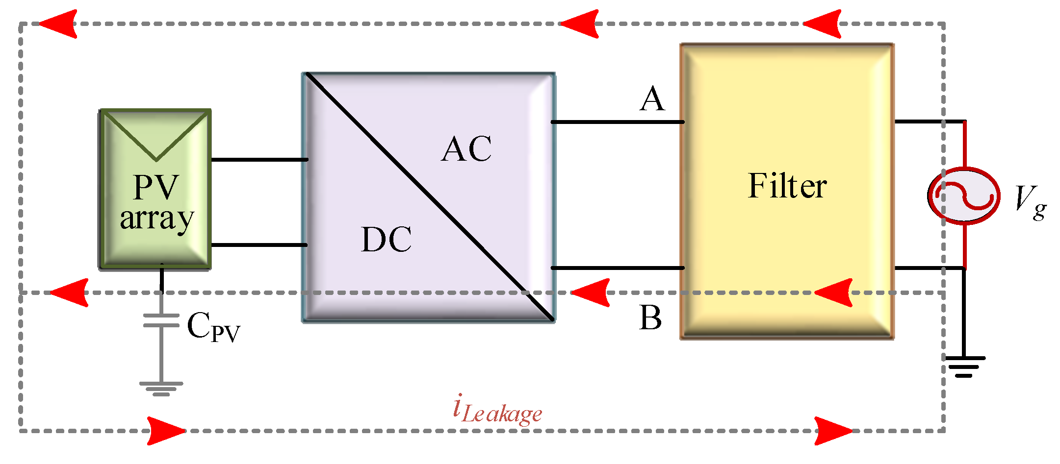
- Eliminates the extra leakage current;
- Keeps the common-mode voltage constant;
- Reduces the harmonics in the grid voltage and current, as well as the losses;
- Increases the inverter performance, even if the solar energy intensity is scarce.
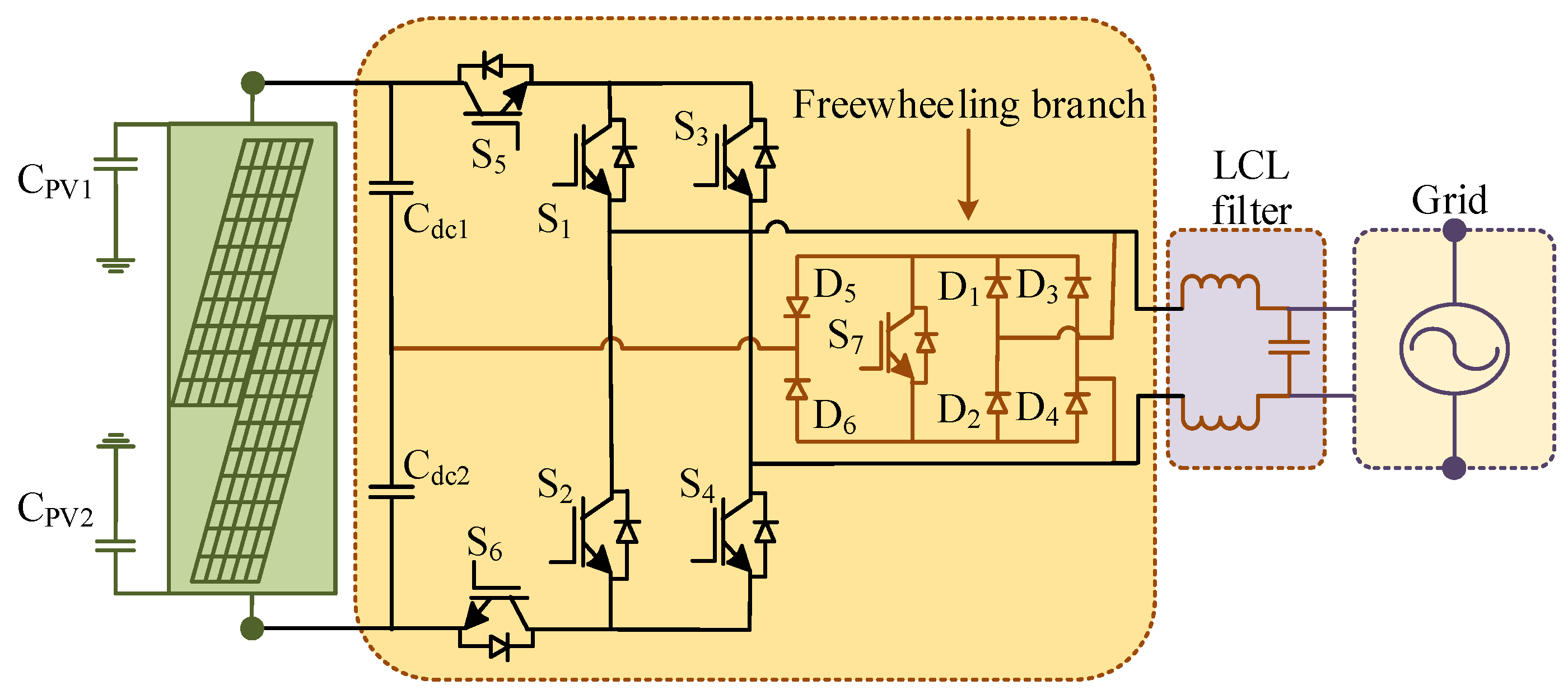
2. Proposed Single-Phase Transformer-Less Inverter
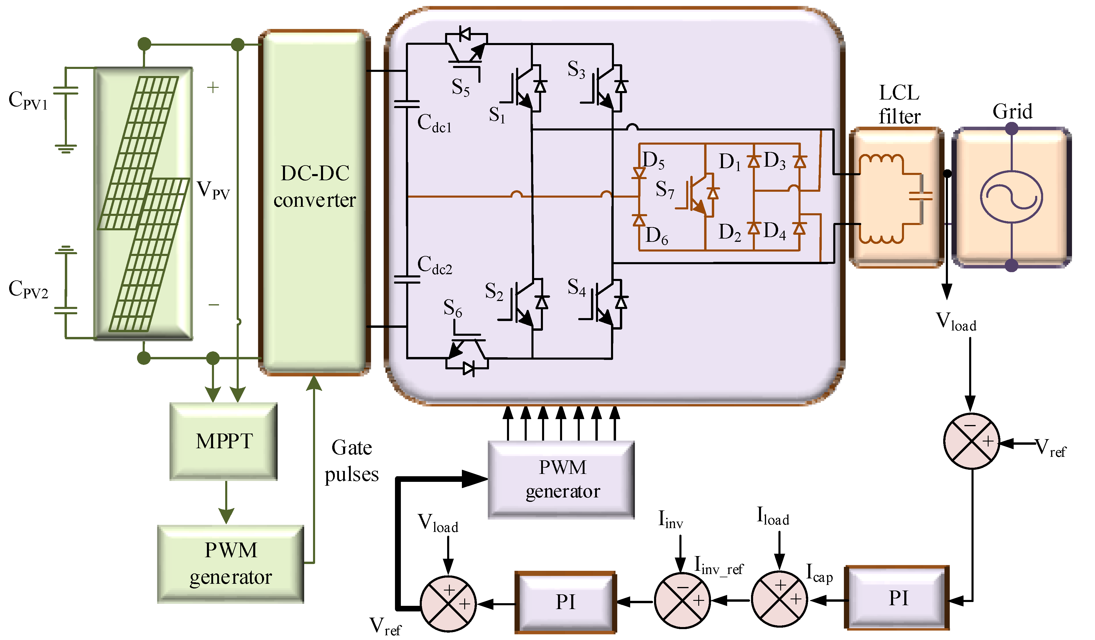
2.1. Structure of the Proposed Transformerless PV Inverter
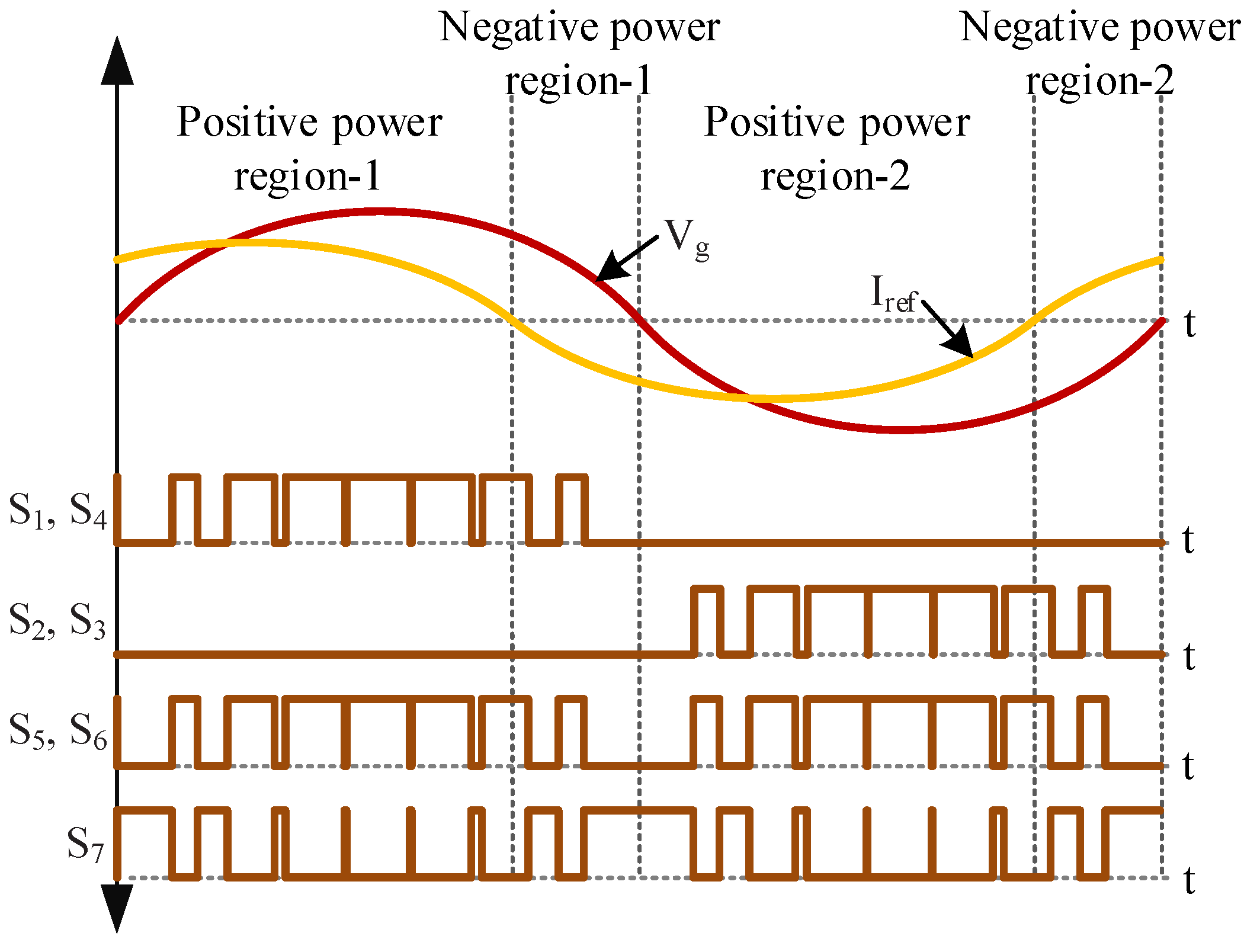
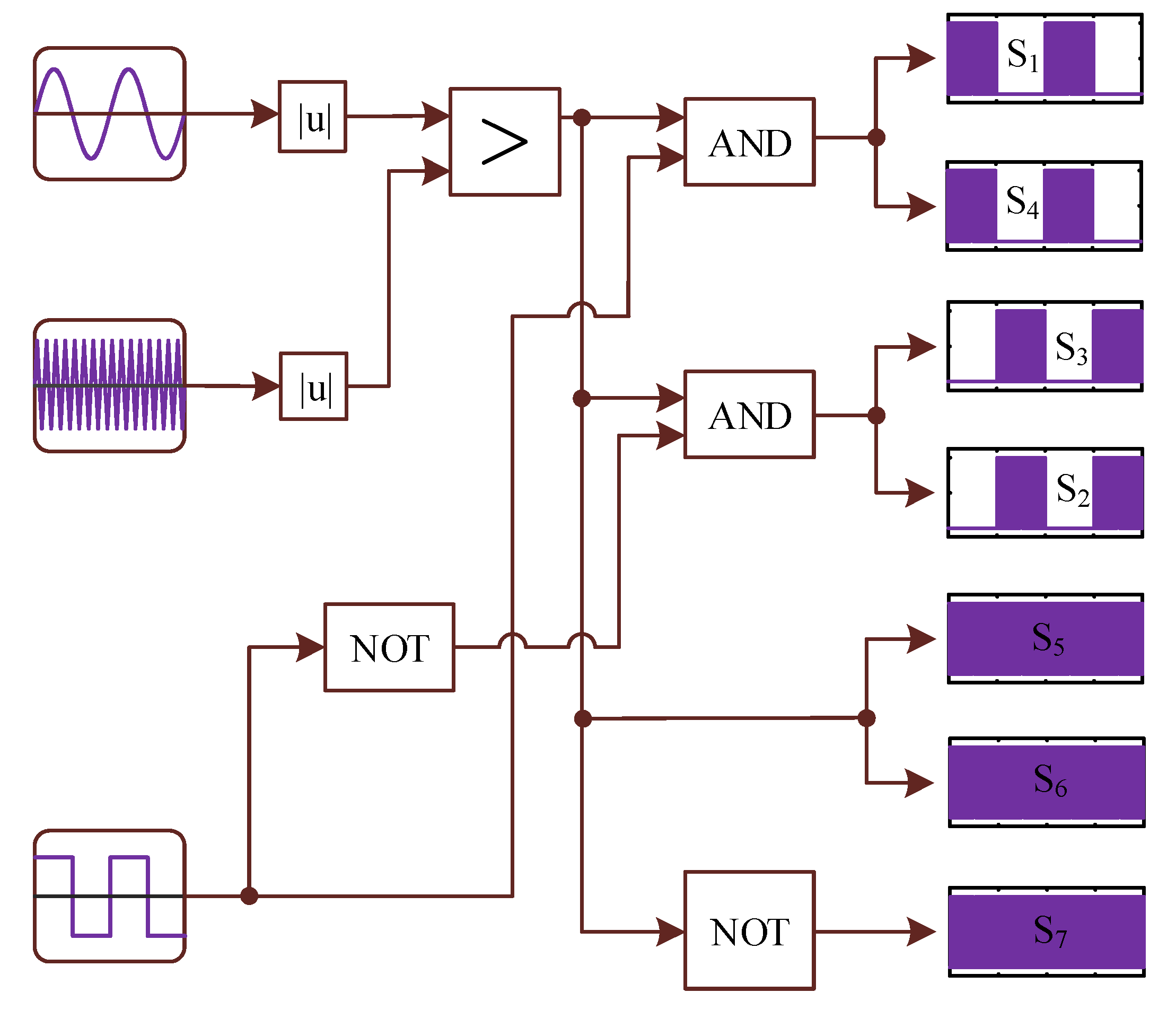
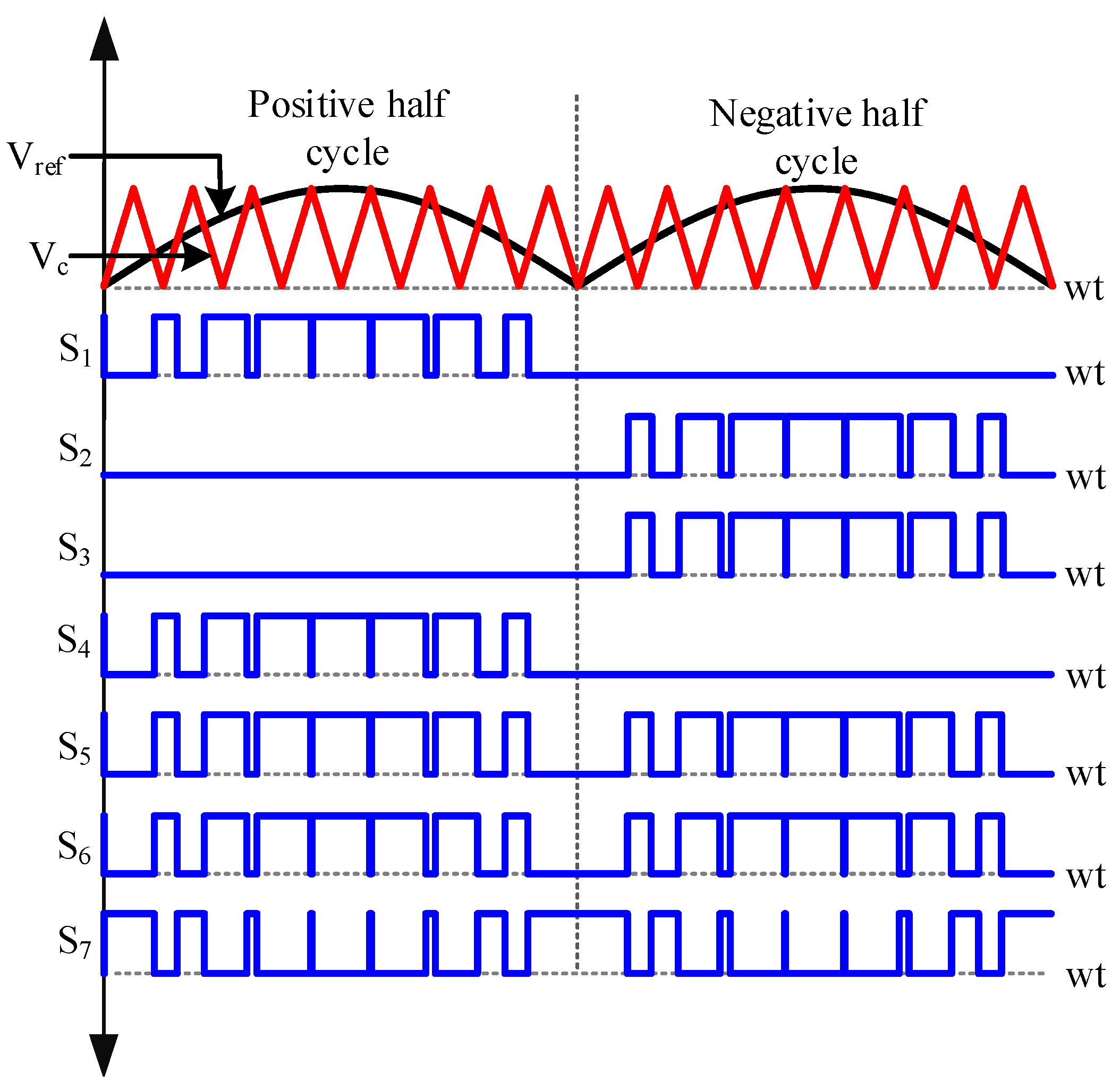
2.2. Modulation Technique
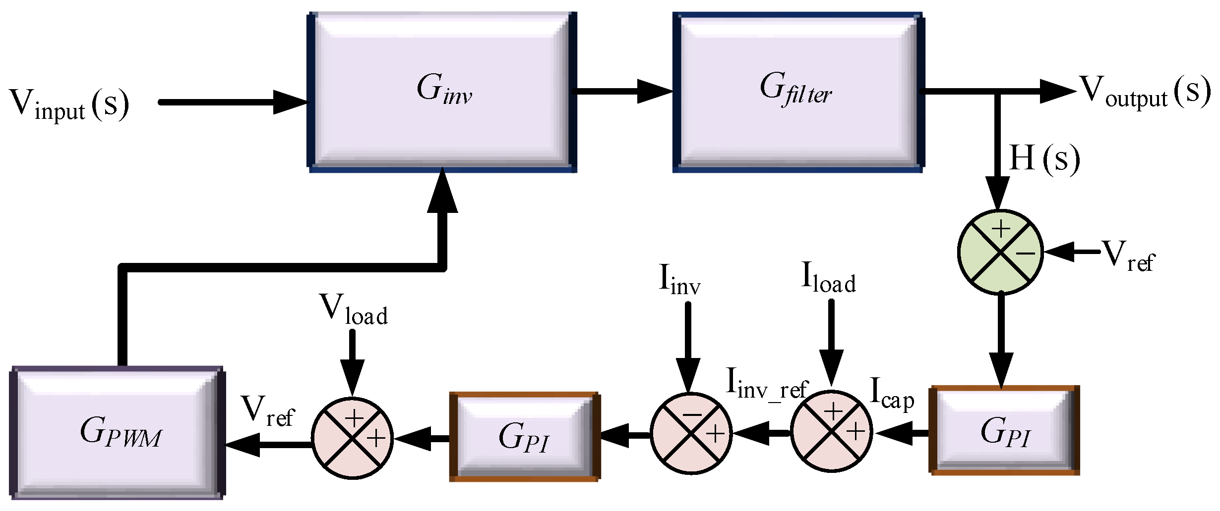
2.3. Control Scheme
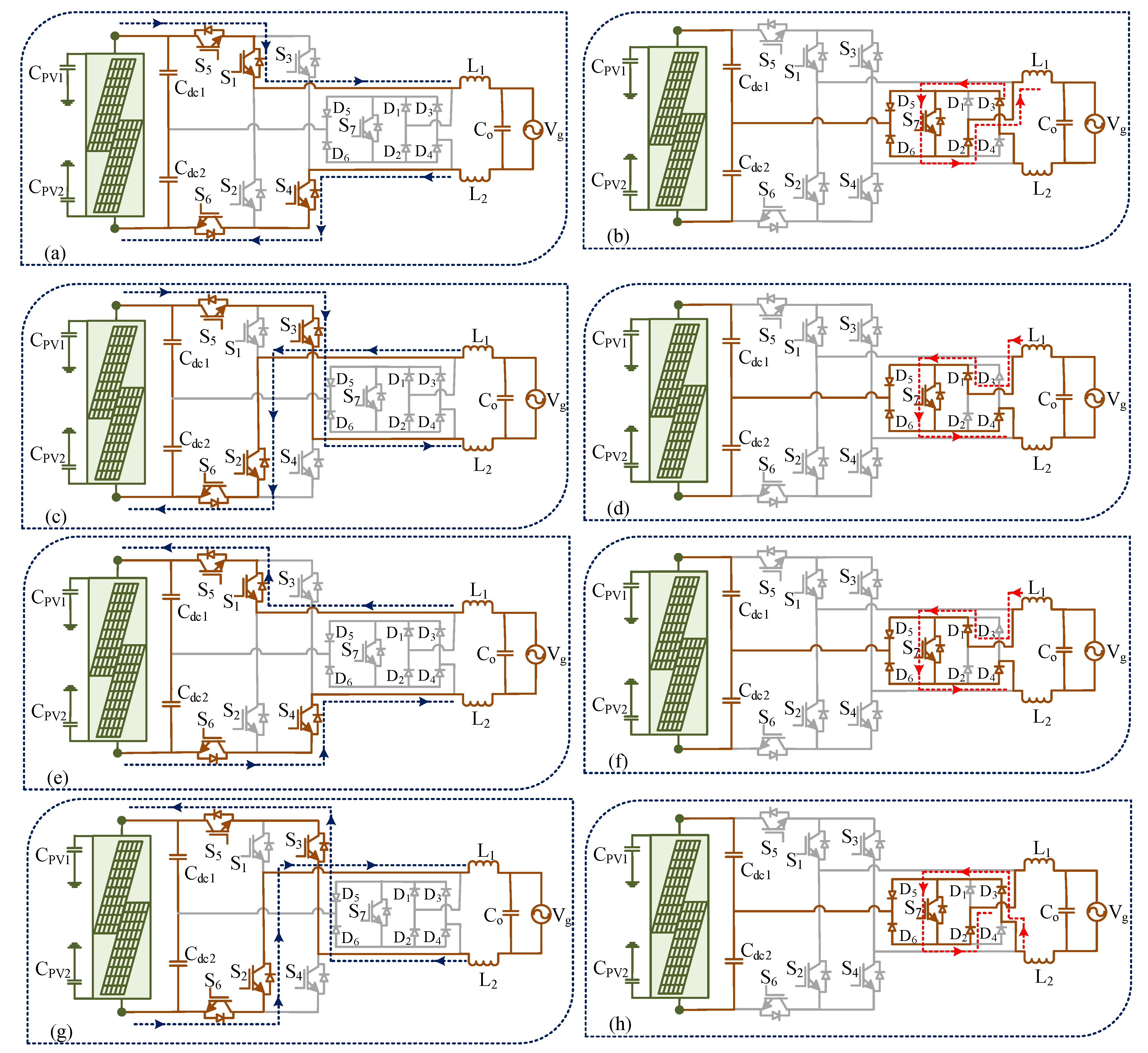
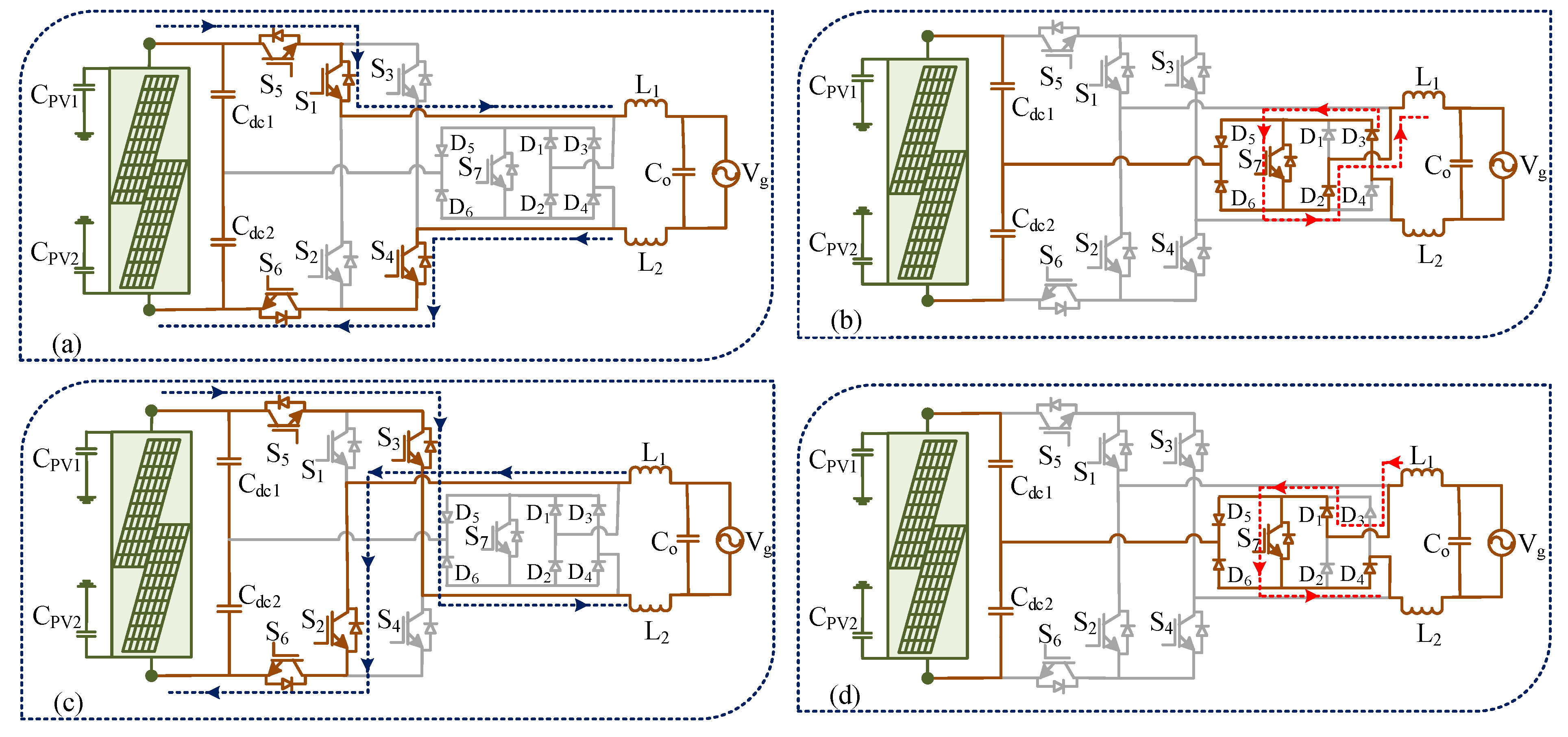
3. Conduction Modes of the Proposed Transformer-Less Inverter
3.1. Conduction Modes in Unity Power Factor Operation
3.2. Conduction Modes under Non-Unity Power Factor
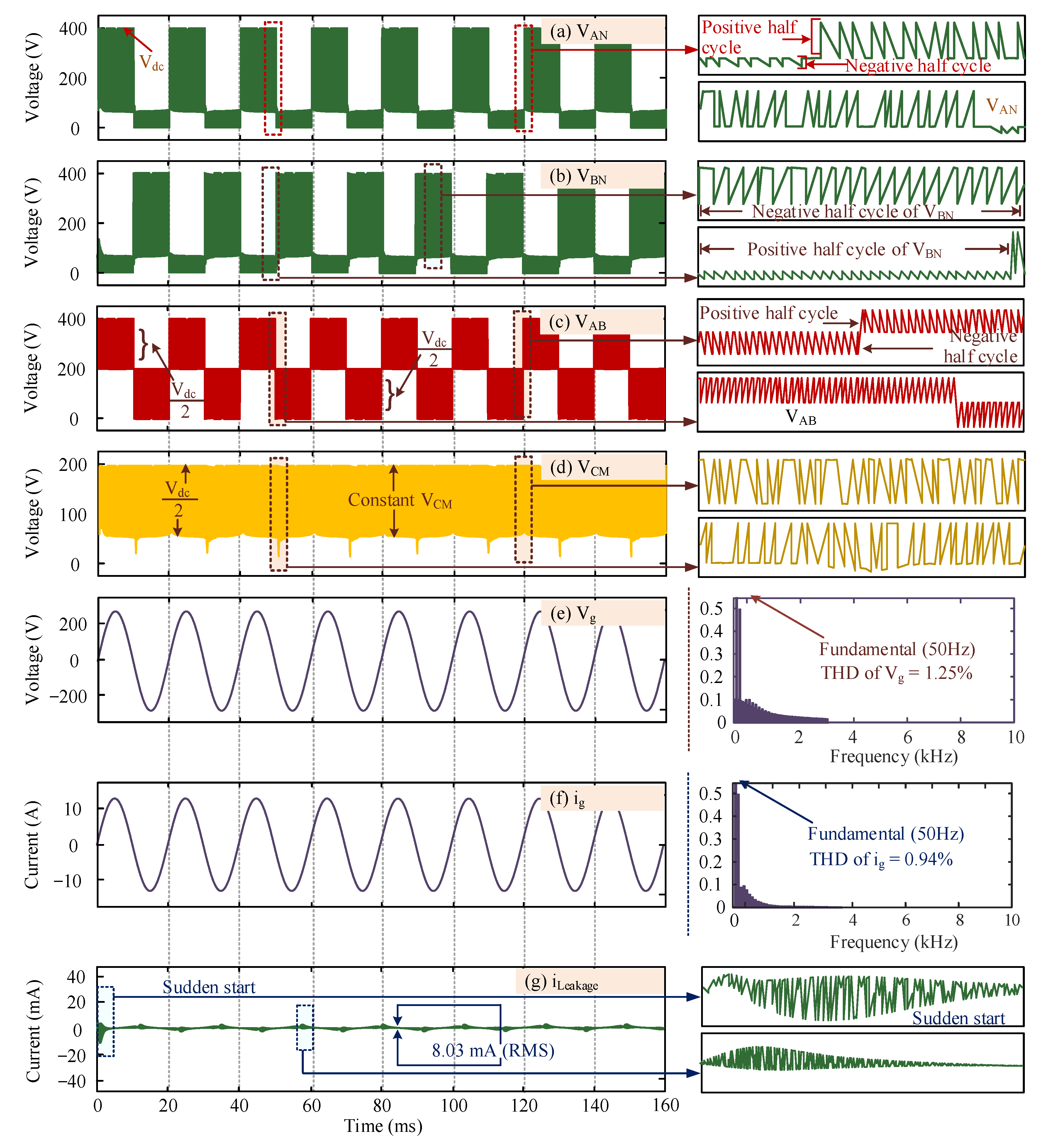
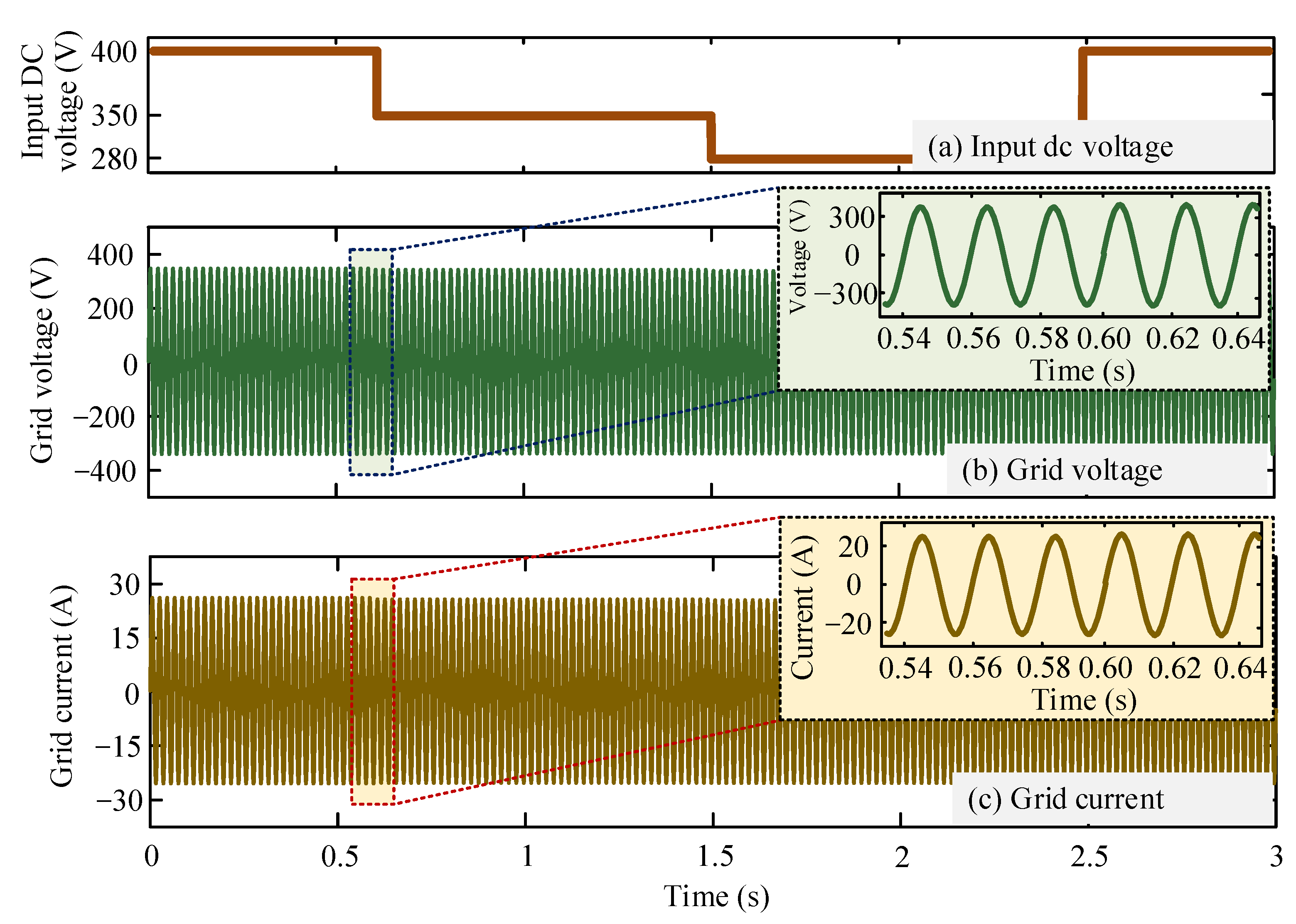
4. Simulation Results
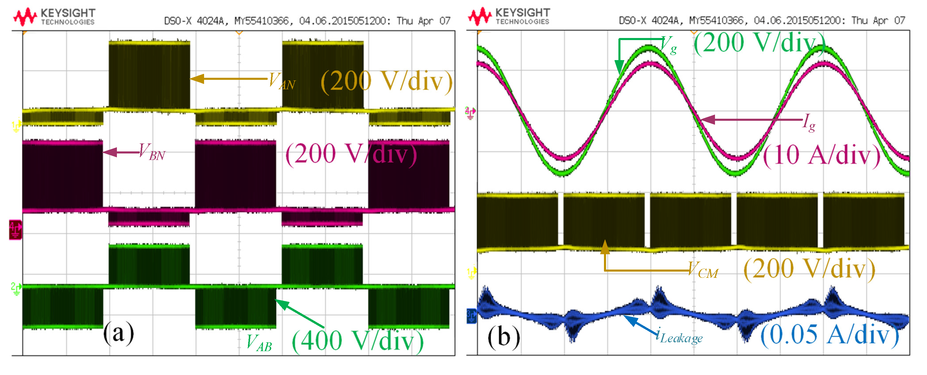
5. Experimental Results
6. Comparison with Other Existing Topologies
7. Conclusions
Author Contributions
Funding
Conflicts of Interest
References
- Rahman, M.A.; Islam, M.R.; Muttaqi, K.M.; Sutanto, D. A modular magnetic linked converter station for offshore power transfer through HVDC link. IEEE Trans. Ind. Electron. 2022, 1–10. [Google Scholar] [CrossRef]
- Biswas, S.P.; Anower, M.S.; Sheikh, M.R.I.; Islam, M.R.; Rahman, M.A.; Mahmud, M.A.P.; Kouzani, A.Z. A modified reference saturated third harmonic injected equal loading PWM for VSC-based renewable energy systems. IEEE Trans. Appl. Supercond. 2021, 31, 5000405. [Google Scholar] [CrossRef]
- Haq, S.; Biswas, S.P.; Hosain, M.K.; Rahman, M.A.; Islam, M.R.; Jahan, S. A modular multilevel converter with an advanced PWM control technique for grid-tied photovoltaic system. Energies 2021, 14, 331. [Google Scholar] [CrossRef]
- Ellabban, O.; Abu-Rub, H.; Blaabjerg, F. Renewable energy resources: Current status, future prospects and their enabling technology. Renew. Sustain. Energy Rev. 2014, 39, 748–764. [Google Scholar] [CrossRef]
- Son, G.; Huang, Z.; Li, Q.; Lee, F. Analysis and control of critical conduction mode high-frequency single-phase transformerless PV inverter. IEEE Trans. Power Electron. 2021, 36, 13188–13199. [Google Scholar] [CrossRef]
- Yang, Y.; Blaabjerg, F.; Wang, H. Low voltage ride-through of singlephase transformerless photovoltaic inverters. IEEE Trans. Ind. Appl. 2014, 50, 1942–1952. [Google Scholar] [CrossRef] [Green Version]
- Chen, B.; Gu, B.; Zhang, L.; Lai, J.-S. A novel pulse-width modulation method for reactive power generation on a CoolMOS and SiC-diode based transformerless inverter. IEEE Trans. Ind. Electron. 2016, 63, 1539–1548. [Google Scholar] [CrossRef]
- Islam, M.; Afrin, N.; Mekhilef, S. Efficient single phase transformerless inverter for grid-tied PVG system with reactive power control. IEEE Trans. Sustain. Energy 2016, 7, 1205–1215. [Google Scholar] [CrossRef]
- Wu, T.-F.; Kuo, C.-L.; Sun, K.-H.; Hsieh, H.-C. Combined unipolar and bipolar PWM for current distortion improvement during power compensation. IEEE Trans. Power Electron. 2014, 29, 1702–1709. [Google Scholar] [CrossRef]
- Freddy, T.K.S.; Lee, J.; Moon, H.; Lee, K.; Rahim, N.A. Modulation technique for single-phase transformerless photovoltaic inverters with reactive power capability. IEEE Trans. Ind. Electron. 2017, 64, 6989–6999. [Google Scholar] [CrossRef]
- Khan, M.A.; Haque, A.; Bharath, K.V.S. Control and stability analysis of H5 transformerless inverter topology. In Proceedings of the 2018 International Conference on Computing, Power and Communication Technologies (GUCON), Greater Noida, India, 28–29 September 2018; pp. 310–315. [Google Scholar]
- Xiao, H.; Xie, S. Leakage current analytical model and application in single-phase transformerless photovoltaic grid-connected inverter. IEEE Trans. Electromag. Compat. 2010, 52, 902–913. [Google Scholar] [CrossRef]
- Schmidt, S.; Siedle, C.; Ketterer, J. DC/AC Converter to Convert Direct Electric Voltage into Alternating Voltage or into Alternating Current. U.S. Patent No. US7046534B2, 16 May 2006. [Google Scholar]
- Gonzalez, R.; Lopez, J.; Sanchis, P.; Marroyo, L. Transfomerless inverter for single-phase photovoltaic systems. IEEE Trans. Power Electron. 2007, 22, 693–697. [Google Scholar] [CrossRef]
- Li, H.; Zeng, Y.; Zhang, B.; Zheng, T.Q.; Hao, R.; Yang, Z. An improved H5 topology with low common-mode current for transformerless PV grid-connected inverter. IEEE Trans. Power Electron. 2019, 34, 1254–1265. [Google Scholar] [CrossRef]
- Akpınar, E.; Balıkcı, A.; Durbaba, E.; Azizoğlu, B.T. Single-phase transformerless photovoltaic inverter with suppressing resonance in improved H6. IEEE Trans. Power Electron. 2019, 34, 8304–8316. [Google Scholar] [CrossRef]
- Li, K.; Shen, Y.; Yang, Y.; Qin, Z.; Blaabjerg, F. A transformerless single-phase symmetrical Z-source HERIC inverter with reduced leakage currents for PV systems. In Proceedings of the 2018 IEEE Applied Power Electronics Conference and Exposition (APEC), San Antonio, TX, USA, 4–8 March 2018; pp. 356–361. [Google Scholar]
- Wang, H.; Wu, W.; Zhu, J.; Koutroulis, E.; Chung, H.S.-H.; Blaabjerg, F. A novel dual buck and boost transformer-less single-phase grid-tied inverter. IEEE Trans. Power Electron. 2022, 37, 4211–4224. [Google Scholar] [CrossRef]
- Lak, M.; Tsai, Y.-T.; Chuang, B.-R.; Lee, T.-L.; Moradi, M.H. A hybrid method to eliminate leakage current and balance neutral point voltage for photovoltaic three-level T-type inverter. IEEE Trans. Power Electron. 2021, 36, 12070–12089. [Google Scholar] [CrossRef]
- Hashempour, M.M.; Liu, F.; Lee, T. Modulation-controlled clamped-three-level inverters supplied by series unbalance battery-banks under asymmetric SOCs. IET Power Electron. 2019, 12, 4034–4042. [Google Scholar] [CrossRef]
- Tsai, M.-J.; Chen, H.-C.; Cheng, P.-T. Eliminating the neutral-point oscillation of the four-wire NPC active power filter. IEEE Trans. Power Electron. 2019, 34, 6233–6240. [Google Scholar] [CrossRef]
- Biswas, M.; Biswas, S.P.; Islam, M.R.; Rahman, M.A.; Muttaqi, K.M. A new H7 transformer-less single-phase inverter to improve the performance of grid-connected solar photovoltaic systems. In Proceedings of the 2021 IEEE Industry Applications Society Annual Meeting (IAS), Vancouver, BC, Canada, 10–14 October 2021; pp. 1–6. [Google Scholar]
- Rocabert, J.; Luna, A.; Blaabjerg, F.; Rodríguez, P. Control of power converters in AC microgrids. IEEE Trans. Power Electron. 2012, 27, 4734–4749. [Google Scholar] [CrossRef]
- Ma, L.; Xu, H.; Huang, A.Q.; Wang, X.; Zou, J. Single-phase hybrid-H6 transformerless PV grid-tied inverter. IET Power Electron. 2018, 11, 2440–2449. [Google Scholar] [CrossRef]
- Xiao, H.; Xie, S.; Chen, Y.; Huang, R. An optimized transformerless photovoltaic grid-connected inverter. IEEE Trans. Ind. Electron. 2011, 58, 1887–1895. [Google Scholar] [CrossRef]


| Parameter Name | Symbol | Value |
|---|---|---|
| Input DC voltage | VDC | 400 V |
| Grid voltage | Vg | 230 V/50 Hz |
| Maximum output power | Pout | 2 kW |
| Switching frequency | fs | 20 kHz |
| DC link capacitor | CDC1 and CDC2 | 940 uF |
| Parasitic capacitor | Cpv1 and Cpv2 | 75 nF |
| Output filter inductor | L1 and L2 | 3 mH |
| Output filter capacitor | C0 | 2.2 uF |
| Topology Name | H5 [11] | oH5 [12] | HERIC [13] | H6 [14] | HBZVR [14] | HBZVR-D [14] | Proposed |
|---|---|---|---|---|---|---|---|
| Number of IGBTs | 5 | 6 | 6 | 6 | 5 | 5 | 7 |
| Number of diodes | 0 | 0 | 0 | 2 | 5 | 6 | 6 |
| PWM pattern | Unipolar SPWM | Unipolar SPWM | Unipolar SPWM | Unipolar SPWM | Unipolar SPWM | Unipolar SPWM | Unipolar SPWM |
| CMV | Floating (~200 V) | Constant | Floating (~200 V) | Constant | Semi-floating (~200 V) | Constant | Constant |
| Leakage RMS current (mA) | 45 | 18 | 48.8 | 15.5 | 74.4 | 42.7 | 8.03 |
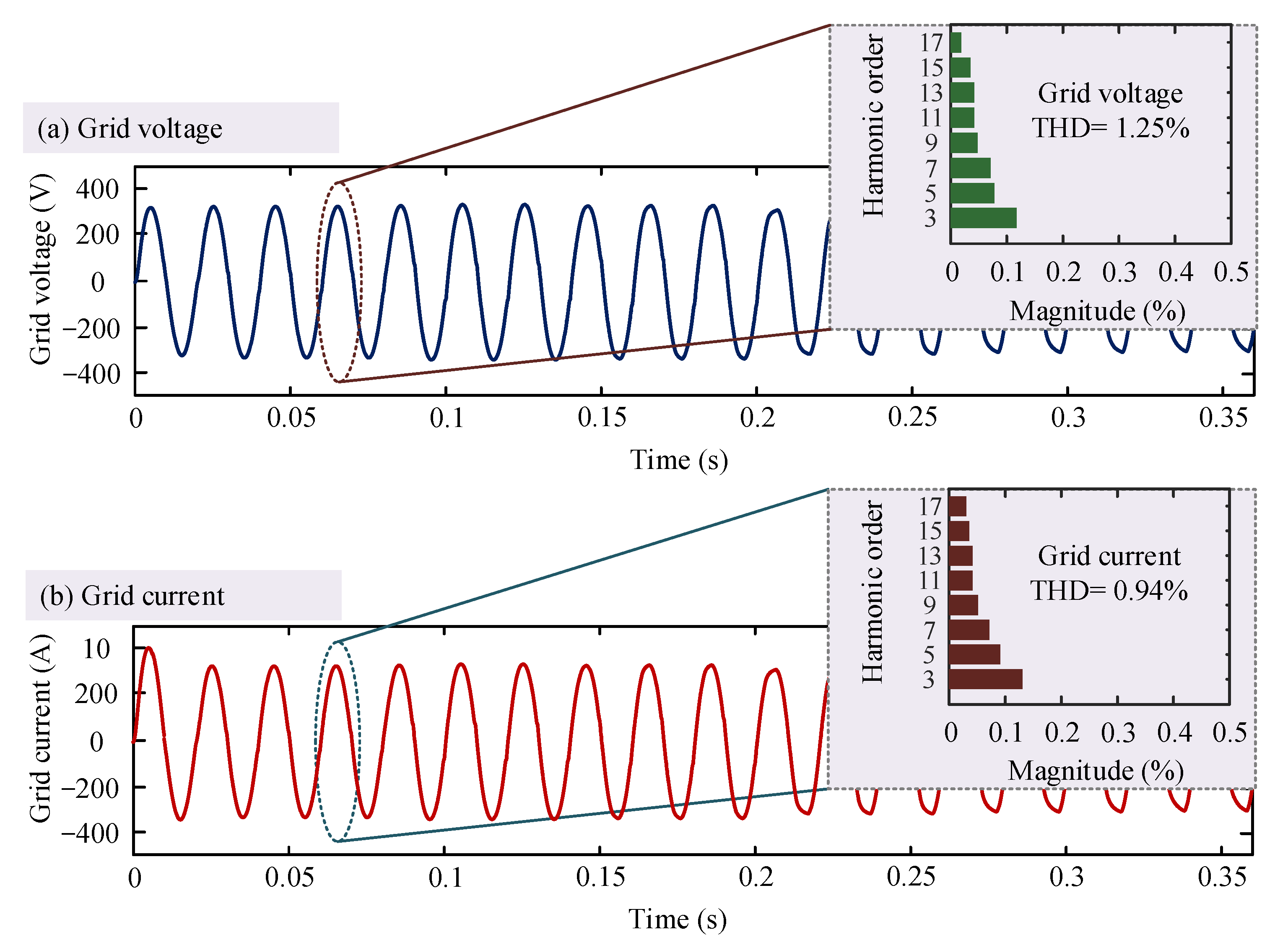
| Grid current THD (%) | 1.5 | 1.5 | 1.5 | 1.5 | 1.9 | 1.9 | 0.94 |
| Efficiency (%) | 97.59 | 97.55 | 98.16 | 97.24 | 97.65 | 97.88 | 97.93 |
Publisher’s Note: MDPI stays neutral with regard to jurisdictional claims in published maps and institutional affiliations. |
© 2022 by the authors. Licensee MDPI, Basel, Switzerland. This article is an open access article distributed under the terms and conditions of the Creative Commons Attribution (CC BY) license (https://creativecommons.org/licenses/by/4.0/).
Share and Cite
Biswas, M.; Biswas, S.P.; Islam, M.R.; Rahman, M.A.; Muttaqi, K.M.; Muyeen, S.M. A New Transformer-Less Single-Phase Photovoltaic Inverter to Improve the Performance of Grid-Connected Solar Photovoltaic Systems. Energies 2022, 15, 8398. https://doi.org/10.3390/en15228398
Biswas M, Biswas SP, Islam MR, Rahman MA, Muttaqi KM, Muyeen SM. A New Transformer-Less Single-Phase Photovoltaic Inverter to Improve the Performance of Grid-Connected Solar Photovoltaic Systems. Energies. 2022; 15(22):8398. https://doi.org/10.3390/en15228398
Chicago/Turabian StyleBiswas, Mohua, Shuvra Prokash Biswas, Md. Rabiul Islam, Md. Ashib Rahman, Kashem M. Muttaqi, and S. M. Muyeen. 2022. "A New Transformer-Less Single-Phase Photovoltaic Inverter to Improve the Performance of Grid-Connected Solar Photovoltaic Systems" Energies 15, no. 22: 8398. https://doi.org/10.3390/en15228398