Article

Fuzzy Logic–Based Decentralized Voltage–Frequency Control and Inertia Control of a VSG-Based Isolated Microgrid System

by
Baheej Alghamdi
1,2
1
Smart Grids Research Group, Center of Research Excellence in Renewable Energy and Power Systems, King Abdulaziz University, Jeddah 21589, Saudi Arabia
2
Department of Electrical and Computer Engineering, Faculty of Engineering, King Abdulaziz University, Jeddah 21589, Saudi Arabia
Energies 2022, 15(22), 8401; https://doi.org/10.3390/en15228401
Submission received: 28 September 2022 / Revised: 28 October 2022 / Accepted: 4 November 2022 / Published: 10 November 2022
(This article belongs to the Special Issue Smart Grid Control and Optimization)

Abstract

:
This work proposes the use of fuzzy-logic-based voltage frequency control (VFC) and adaptive inertia to improve the frequency response of a virtual synchronous generator (VSG)-based isolated microgrid system. The joint VFC and inertial control scheme is proposed to limit frequency deviations in these isolated microgrid systems, mainly caused by the increasing penetration of intermittent distributed energy resources, which lack rotational inertia. The proposed controller uses artificial neural networks (ANN) to estimate the exponent of voltage-dependent loads and modulate the system frequency by adjusting the output voltage of the VSGs, which increases the system’s active power reserves while providing inertial control by adjusting the inertia of VSGs to minimize frequency and VSG DC-link voltage excursions. A genetic algorithm (GA)-based optimization strategy is developed to optimally adjust the parameters of the fuzzy logic controller to diminish the impact of disturbances on the system. In addition, the proposed technique is illustrated through simulations within the framework of a test system based on the CIGRE medium-voltage benchmark under various circumstances. The results of these simulations demonstrate that the proposed control strategy outperforms existing methods.

1. Introduction

The increase in distributed energy resources (DERs) over the last decade has transformed distribution networks from passive to active, with DERs contributing to the supply of local loads within distribution networks, leading to the development of microgrids [1]. Microgrids are medium- or low-voltage networks comprising loads and DERs capable of meeting the load system’s demand independent of the host grid. Owing to the significant prevalence of inverter-based DERs, which lack inertia, and the availability of intermittent renewable energy sources (RES), microgrids are vulnerable to severe frequency excursions [1]. The widespread use of voltage source converter (VSC)-based DERs primarily alters the power system’s dynamic behavior because their mechanical time constant is shorter than that of traditional synchronous generators and they lack inertia and damping property, which would cause significant frequency excursions in isolated microgrid systems [2]. Several control approaches have been proposed to address the issue of rapid frequency excursions in microgrids. In [3,4], the authors proposed a virtual synchronous generator (VSG) with alternating inertia to minimize frequency excursions and power oscillations. However, the proposed technique relies solely on the energy storage of the battery energy storage system to provide inertia without considering the impact of the VSG output voltage on the system frequency. In addition, a systematic approach for the selection of inertia constants and their impact on the DC-link voltages of VSGs was not addressed. The authors in [5] proposed an enhanced version of the VSG, which includes alternating inertia that proportionally adjusts the inertia constant according to the severity of the disturbance. The proposed VSG also utilizes voltage—frequency control (VFC) to regulate the system’s frequency; however, the presented VFC does not consider the impact of the changes in the microgrid load exponent on the microgrid’s frequency regulation. Furthermore, the selection of the inertia constants of the VSGs is not based on an optimization approach that considers the impact of inertia on the DC-link voltages of the VSG. In [6,7], the authors provided a generic VSG and investigated the impact of the moment of inertia and damping on the small perturbation of the system without considering the frequency regulation of an isolated microgrid and neglecting the modeling of the DC side of VSGs. In [8], the authors investigated the impact of virtual synchronous impedance on the small-perturbation stability properties of a VSG, where it was demonstrated that poorly damped oscillations may appear owing to the improper selection of virtual synchronous impedance. However, frequency regulation, VFC, and inertial control have not been presented. In [9], the authors developed a control system for VSGs which damps low-frequency power oscillations in microgrids. However, the presented control scheme assumes VSG active power is independent of the voltage change, and the control scheme is not investigated in the presence of voltage-dependent loads. In [10], the authors proposed a combined VSG control system to modulate virtual stator reactance and reactive power to effectively share both active and reactive power transients and damp power oscillations. The proposed reactive power controller, however, is based on a typical inversed voltage droop control (V-Q droop control) and does not take into account the impact of a potential coupling between active and reactive power caused by voltage-dependent loads. Additionally, the study does not consider the controllers in the context of frequency regulation. In [11], the authors proposed connecting a VSG in parallel with a synchronous generator (SG) to reduce the SG’s load and limit the system’s frequency deviation. However, the presented control scheme does not consider the impact voltage control and the frequency control of the system, and an optimization approach is not considered in tuning the VSG inertia controller.
In [12], the authors reviewed different layouts and VSG architectures, including voltage-controlled and current-controlled VSGs. However, coordinated frequency control while considering VSG inertial control and VFC has not been presented. In [13,14], the authors investigated the influence of voltage regulation on the VSG fault ride-through capacity by presenting a controller that predicts the grid voltage and utilizes it as the inverter output’s reference voltage. When the grid voltage drops owing to a voltage sag, the controller reduces the inverter output voltage to avoid an overcurrent. However, this controller can only improve the VSG fault ride-through and cannot be extended to adjust the microgrid frequency through voltage control.
Other studies on frequency control in isolated microgrids employ voltage control [15,16]. These studies proposed a control system for controlling the frequency of an isolated microgrid by modifying the operating voltage of the microgrid owing to the existence of voltage-dependent loads. However, the presented controller is only integrated into conventional inverter-based DERs, without considering its utilization in VSGs to supplement virtual inertial control. Furthermore, the presented controller does not consider the effects of abrupt changes in the microgrid load exponent, especially when there is a rapid shift in the penetration of voltage-dependent loads, and the subsequent influence on microgrid frequency regulation.
A systematic control synthesis approach for an ideal VFC in islanded/isolated microgrids is presented in [17]. However, the drawbacks of the aforementioned VFC studies are observed here. The authors of [18] describe a centralized control strategy that makes use of VFC and adaptive droop control to regulate the frequency of isolated microgrids. However, since it is centralized, the control system has problems with single-point failure, which may cause reliability and scalability difficulties.
This work presents a combined inertial and voltage control method to address the limitations of the previously discussed VSG control systems. The primary contributions of this study are summarized as follows:
  • The development of a fuzzy logic control system that combines VFC with inertial control to regulate the frequency of isolated microgrids that face considerable frequency excursions due to a lack of inertia and reduce the effect of disturbances on the systems.
  • The proposed control strategy employs artificial neural networks (ANNs) to estimate the microgrid load exponent that fuzzy-logic-based controllers use to alter the system voltage and the inertia constants of VSGs. This alteration improves isolated microgrids’ frequency response and regulation by sharing load power between VFC and active power control loop according to the sensitivity of the system’s voltage-dependent loads. Conversely, conventional VFC control techniques depend heavily on the system’s load characteristics, limiting their ability to regulate the frequency of the system.
  • A genetic algorithm (GA) optimization approach is proposed to properly tune the parameters of the proposed fuzzy logic controllers, considering several performance indices, such as deviations in the system’s frequency and VSG’s DC-link voltage to minimize the impact of disturbances on the system.
The remainder of this paper is organized as follows. Section 2 examines the fundamentals of VSGs in microgrids and models microgrid components. The proposed fuzzy-logic-based frequency controllers are introduced and explained in Section 3. Section 4 presents time-domain simulations of several studies performed on a modified CIGRE benchmark microgrid. These simulations were intended for validating the proposed method and to compare the proposed approach with other methods. Finally, Section 5 summarizes and emphasizes the study’s primary findings.

2. Overview of VSG and Modeling of Microgrid Components

The proposed VSG control technique is intended for isolated microgrids based on inverter-based grid-forming DERs, which face several technical challenges, including significant and rapid frequency excursions caused by supply demand mismatches due to intermittent renewable energy sources (RESs) and the lack of inertia associated with synchronous machines (SGs).

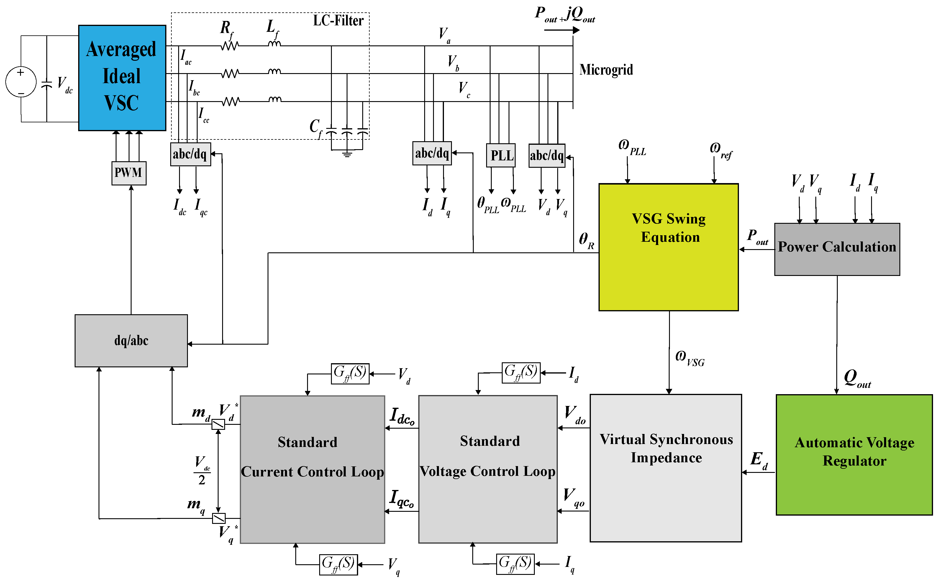
2.1. Virtual Synchronous Generators Modeling

The proposed controller is incorporated into VSGs, which function like synchronous generators (SGs) by simulating their inertia and damping properties in the controllers of inverter-based DERs [5,12]. Various models in the literature have been created to simulate the dynamics of SGs in VSCs, most of which are voltage-controlled and hence subject to inaccuracies owing to the absence of VSC current regulation loops. Other models rely on the VSC output current regulation and a phase-locked loop (PLL) to connect to the grid. The generic VSG control method utilized here is based on [6,19] and comprises hierarchical voltage and current control loops that use the virtual VSG rotor angle of the inner-swing equation model as a reference.

2.2. VSG Swing Equation and Automatic Voltage Regulator

The basic design of a VSG is based on [5,6], which is more thorough than ordinary voltage-controlled VSGs and comprises numerous control loops, as shown in Figure 1.
The virtual implementation of the second-order SG swing equation governs the main dynamics of a VSG [12,20]:
P g o v P o u t = J ω V S G d ω V S G d t + D ( ω V S G ω P L L )
θ R = ω V S G d t
where P o u t is the VSG active output power, P g o v is the VSG governor’s power, D is the damping coefficient, J is the virtual moment of inertia coefficient, ω P L L is the PLL estimated angular frequency, ω V S G is the angular velocity of the VSG, and θ R is the virtual rotor angle used to synchronize the VSG to the microgrid.
A droop controller is implemented in the VSG governor to share the load demand proportionally among the VSGs. The VSG governor is modeled as follows [5]:
P g o v = K P g o v ( ω r e f ω V S G ) 1 + τ g o v s + P o
where P o is the VSG reference active power, K P g o v is the VSG droop coefficient, and τ g o v is the virtual turbine and governor time constant.
The VSG field voltage E d is provided by AVR, which is then utilized to perform reactive power sharing through droop control, as shown below:
E d = V o V o u t + K Q ( Q o Q o u t ) + G Q ( s ) ,
where V o u t denotes the VSG output voltage, Q o denotes the reference reactive power, G Q ( s ) denotes the AVR PI controller, Q o u t denotes the VSG output reactive power, V o denotes the reference terminal voltage of the VSG, and K Q denotes the VSG reactive power droop coefficient.

2.3. VSG Voltage Control Loops

The AVR provides the inner field voltage E d , which is delivered to the voltage control loop to govern the VSG output voltages. Thus, the references of the voltage control loop, V d o and V q o , are as follows [5]:
V d o = E d + X s I q R s I d
V q o = 0 X s I d R s I q
where R s + j X s denotes the virtual synchronous impedance. In the voltage control loop, the reference dq currents for the inner current control loop are derived as:
I d c o = ( V d o V d ) G V ( s ) V q ω V S G C f + I d G f f ( S )
I q c o = ( V q o V q ) G V ( s ) + V d ω V S G C f + I q G f f ( S )
where G V ( s ) is the PI controller of the voltage control loop, G f f ( S ) is the first-order transfer function of a feed-forward filter, and I d and I q are the dq-axis components of the output VSG current. To prevent the VSC from overcurrent, we used hard limits to constrain the reference currents.

2.4. Current Control Loop

The decoupling dq components V d * and V q * are produced by the inner current control loop and provided to the dq/abc converting block to serve as a reference for the VSC, as follows [5]:
V d * = ( I d c o I d c ) G I ( s ) I q c ω V S G L f + V d G f f ( S )
V q * = ( I q c o I q c ) G I ( s ) + I d c ω V S G L f + V q G f f ( S )
where G I ( s ) denotes the PI controller of the current control loop. A buck-boost converter is used to regulate the DC-link voltage as follows:
V d c r e f = V d c o 2 V d c 2 G d c ( s ) ,
where V d c is the measured DC-link voltage, G d c ( s ) is the PI regulator of the DC-link voltage, and V d c o is the reference DC-link voltage.

2.5. VSG Output Power Calculation Block

The injected VSG active and reactive power are calculated from the dq-axis components of the output VSG current and voltage, as follows [21]:
p o u t = 3 2 V d I d + V q I q
q o u t = 3 2 V q i d V d i q
The instantaneous active p o u t and reactive q o u t powers are processed through low-pass filters G f f ( S ) in order to extract the corresponding fundamental P o u t and Q o u t components.

2.6. PLL Block*

The PLL block is used to track the actual microgrid frequency. The three-phase PCC voltages ( V a , V b , and V c ) are used as a PLL’s inputs. Based on an angle θ P L L , the voltages will be transformed into dq-axis voltages. The PLL’s outputs include dq-axis voltage magnitudes V d and V q , estimated angular frequency ω P L L , and the angle θ P L L [6,21].

2.7. Wind Generator Model

As described in [15,18,21], wind generators (WGs) are considered type 4 with complete VSC interfaces. The presented model of the WGs utilizes an average model of the VSC detailed in [21] and is like the converter depicted in Figure 2 for the BESS.

2.8. Voltage-Dependent Load Modeling

An exponential voltage-dependent model was used to depict the loads on the system [15,18]:
P = P 0 V L V 0 n p l l
Q = Q 0 V L V 0 n q l l
where the exponents n p l and n q l define the type of load, V L is the load voltage, which is equivalent to the microgrid voltage, and P 0 and Q 0 are the rated powers for load l. According to [15], a significant fraction of the loads in microgrids are constant impedance loads. As shown in (14) and (15), the load demand is sensitive to variations in the voltage. Consequently, the microgrid voltage affects the load demand.

Load Response to Microgrid Voltage Deviation

The loads of a microgrid system generally consist of a range of electrical equipment that influence the microgrid’s response to voltage deviations. For resistive loads such as lighting and heating, the electrical power depends on the system voltage. The frequency-dependent overall property of a composite load can be expressed as follows [18]:
Δ P L = l = 1 N L K P l ( V M G + Δ V M G ) α P l V M G α P l
where K P l and α P l are the parameters of the l t h voltage-dependent load power K P l V α l and V M G is the microgrid voltage, assuming that the losses are negligible [22]. Thus, a change in the VSG output voltage would change the microgrid load demand.

3. Proposed Fuzzy-Logic-Based Decentralized Frequency Control Scheme

The proposed control technique of the VSG-based microgrid system consists of three controllers: a distributed active power control loop, decentralized fuzzy-logic-based voltage–frequency control, and decentralized fuzzy-logic-based adaptive inertia control. The general purpose of these controller suites is to reduce the frequency deviations caused by rapid fluctuations in the DER output power of the microgrid and abrupt load surges, as well as to restrict the rate of change in frequency deviation. To meet the performance constraints, practitioners tune these controllers collectively using a genetic algorithm (GA), as described in Section 3.3.

3.1. Proposed Fuzzy-Logic-Based VFC

The VFC-based fuzzy logic controller aims to regulate the frequency of the microgrid by modulating the VSG output voltage and exploiting the voltage dependency of the microgrid loads. However, power sharing between the VFC and active power control loops must be addressed. The active power frequency control loop consists of a PI controller, which is defined as follows:
Δ P D E R i = α D E R i K f P f r e f f P L L + K f I f r e f f P L L d t
D E R = 1 n α D E R i = 1 , 0 α D E R i 1
where K f P and K f I are the PI controller parameters, f r e f and f M G are the reference microgrid frequency and the actual microgrid frequency, respectively, and α D E R i is the power-sharing coefficient of DER i to share the power proportionally among the DERs according to their ratings.
The generated secondary control term is subsequently fed to both the virtual governor in Figure 3 and the VFC-based fuzzy logic controller shown in Figure 4, which depicts the VFC-based fuzzy logic controller integrated into the AVR of the VSG. The VFC-based fuzzy logic controller has three inputs: the change in the frequency of the microgrid or the angular velocity of the VSG ( Δ ω V S G ), decentralized secondary control term Δ P D E R i , and equivalent microgrid load exponent n p , which is approximated as follows [15]:
Δ P D = ( V + Δ V ) n p V n p P 0 V 0 n p
n p 2 × Z P + 1 × I P + 0 × P P Z P + I P + P P ,
where P o is the rated active power, V 0 is the nominal operating voltage, V is the microgrid voltage, and P P , I P , and Z P are the constant power, constant current, and constant impedance parameters, respectively. The authors in [15] assumed n p is a deterministic fixed value, which is not realistic for real systems and may result in a poor performance of the VFC, especially if the penetration of voltage-insensitive loads suddenly increases. Therefore, the proposed controller adaptively adjusts the power sharing between the VFC and active power control loop according to the microgrid load exponent. Figure 5 shows the frequency changes in a microgrid because of changes in microgrid voltage, DER output power, and load power. Δ P L represents the change in the system demand, Δ P D E R indicates the change in the total microgrid generation, Δ P V represents the change in the voltage-dependent loads in Figure 5, and n p represents the microgrid load exponent. Consequently, a change in the system frequency induced by the demand variation changes the output active power of the VSG. In contrast, the demand for voltage-dependent loads varies with an inverted gradient, depending on the operating voltage of the microgrid. For example, lowering the frequency of the microgrid produces more VSG output active power, while lowering the VSG output voltage has less power consumption for voltage-dependent loads. Therefore, the microgrid frequency can be regulated by controlling the VSG output voltage. According to the value of n p , the proposed controller adjusts the load power sharing between the voltage control loop and active power control. If the value of n p is high, the penetration of the voltage-dependent loads of the microgrids is high; in this case, the voltage control loop would take priority over the active power control loop in the frequency regulation of the microgrid. Otherwise, the frequency regulation is primarily done by the active power control loop.
The proposed controller uses artificial neural networks (ANNs) to estimate the equivalent microgrid load exponent from the local measurement of microgrid voltage and frequency. The ANN is depicted in Figure 6, which is trained to estimate the microgrid equivalent load exponent from two input data: the frequency of the microgrid and voltage, obtained from the system described in Section 4. The parameters of the ANN are shown in Table 1, which are based on [14]. The training algorithm used to train the ANN is based on Levenberg–Marquardt back-propagation with the default number of epochs. The estimated load exponent of the microgrid obtained from the ANN is fed to the VFC-based fuzzy logic controller, which is based on the Takagi–Sugeno–Kang type inference system and employs symmetrical three-segment triangular membership functions for input variables. The cornerstone of the fuzzy logic operation is the fuzzy rule, which maps the input domain to the output domain. The fuzzy rules, along with the input membership functions, are optimized to satisfy the desired frequency regulation, which is discussed in Section 3.3.

3.2. Decentralized Fuzzy-Logic-Based Adaptive Inertia

The advantage of VSGs over conventional SGs is their ability to adjust their inertia constant, thus providing extra inertia to isolated microgrid systems, especially during severe disturbances.
The VSG dynamics at a given output power and voltage are determined by the coefficients of the second-order differential equation. These coefficients are the moment of inertia constant J and damping constant D. The moment of inertia is defined as [14]
J = 2 H S b ω 0 2 ,
where H is the VSG inertia constant, S b is the base power of the VSG, and ω 0 is the microgrid frequency. Thus, a larger moment of inertia constant decreases the system’s frequency deviation. However, the selection of the moment of inertia constant also affected the dominant poles of the system. For instance, if a given VSG is connected to a grid, the characteristic equation of a linearized swing equation is given by [23]
s 2 + 2 ξ ω n s + ω n 2 = 0
where ω n is the undamped natural frequency and ξ is the damping ratio defined as follows:
ξ = D 4 H ω n
Hence, the inertia constant affects the damping ratio of the system’s dominant poles. Furthermore, as observed in Figure 1, the converter’s DC-side power is typically equal to the AC side when converter losses are ignored for an average model of the converter, which leads to power oscillations propagating to the DC side of the converter, which may lead to DC-link voltage collapse. Thus, an optimization method is proposed to minimize the microgrid frequency deviation and VSG DC-link voltage deviation by selecting suitable values for the inertia of the VSG. The proposed fuzzy logic controller that adjusts the inertia of the VSG is depicted in Figure 7, which has two inputs: the rate of change in the frequency d ω d t and DC-link voltage deviation Δ V d c . The parameters of the proposed controller are tuned using the GA described in Section 3.3.

3.3. Optimization-Based Tuning of the Proposed Fuzzy Logic Controller

To obtain optimal performance using the proposed fuzzy logic controllers, a GA method is implemented to tune both the membership functions and the fuzzy rules. The equations and dynamic models presented in Section 2 and Section 3, which define the VSG, DERs, fuzzy controllers, and the microgrid, are simulated in a time-domain simulation software (PSCAD) using MATLAB V9.10 to perform the proposed optimization. The objective function is calculated as follows:
I T A E = 0 t p f | Δ ω V S G | + p p | i = 1 N D E R Δ P D E R i n p | + p d f | d ω V S G d t | + p d c | i = 1 N D E R Δ V D C i | d t
where p f , p p , p d f , and p d c are the penalties on the angular velocity deviation Δ ω V S G , secondary active power control term Δ P D E R i n p , rate of change in the angular velocity d ω V S G d t , and DC-link voltage deviation Δ V D C i . Note that the term Δ P D E R i n p is also penalized by the microgrid load exponent n p ; thus, if n p is high, which indicates dominant resistive loads in the microgrids, the implemented fuzzy VFC would share more power compared with the active power secondary control. Otherwise, if n p is low, the active power secondary control will share more power than the VFC.
First, the default initial population size was chosen. Each member of the initial population had a unique objective function [24]. Thereafter, the algorithm generates a new population based on the objective function. The optimization approach entails the repeated completion of the procedures shown in Figure 8. The system is perturbed through a unit increase in load demand. The proposed GA optimization is then used to minimize the objective function (24) until the optimization converges, yielding the required controller parameters, resulting in all DERs running at their rated power. The GA is then used to minimize the objective function (24) until the optimization converges, yielding tuned fuzzy-logic controller parameters. Table 2 and Table 3 list the settings of the GA used to optimize the parameters of the fuzzy logic controllers. The parameters of the VSG DERs are shown in Table 4. The tuned input membership functions are shown in Figure 9 and Figure 10, the tuned fuzzy rules are listed in Table 5 and Table 6, and the tuned output membership functions are shown in Figure 11 and Figure 12. The output membership functions in Figure 11 and Figure 12 are of the constant type, which is typically employed in Sugeno fuzzy systems.

4. Simulation Results and Scenarios

The proposed fuzzy-based controllers discussed in Section 3.3 were assessed using a revised version of the CIGRE benchmark microgrid used in various studies [15,16,21,25,26]. Figure 13 depicts the topology of the benchmark microgrid system developed for time-domain simulations in PSCAD, utilizing a PSCAD–MATLAB interface to apply the optimization technique outlined in Section 3.3.
The overall load of the microgrid system was approximately 7 MVA, with a constant power of 10%, constant current of 30%, and constant impedance of 60%. This situation was considered imbalanced, similar to the original CIGRE microgrid system presented in [15,16]. As explained in Section 2, the dynamic models of the WGs and loads in the system are similar to those used in the existing CIGRE microgrid system. The system is composed of four VSG units, each rated at 1.7 MVA. All microgrid WGs were assumed to be Type 4, modeled according to [21], with a rated output of 1.025 MW each and operating at a unity power factor. The feeders are represented by connected π sections [15]. The proposed controllers were implemented in VSG DERs, as shown in Figure 4 and Figure 7.

4.1. Validation and Comparison

The base case is first presented for comparison and illustrates the impact of VSG intermittent power on the microgrid’s frequency. Figure 14 depicts the frequency response of the microgrid in the base-case scenario, which illustrates the effect of fluctuations in the WG output power on the microgrid frequency. The output electricity of the WGs was collected from a real microgrid system [27]. In this instance, the DERs are implemented without the proposed fuzzy controllers and employ only conventional droop controllers.
The effectiveness of the proposed controller was demonstrated by comparing its performance with those of other current control techniques [15,16]. The three schemes that are compared are the VSC with active power control loop [14], VSC with VFC [16], and the proposed VSG with fuzzy logic controllers. A sudden increase in the system demand corresponds to t = 100 s, where the output power of the WGs is at its lowest. The simulation results are depicted in Figure 15, where existing control approaches are vulnerable to severe frequency excursions and the frequency deviates beyond the 0.2 Hz limit [28]. Figure 16 shows statistics of the system’s frequency response, where the average frequency of the system is regulated to the nominal value with the proposed controller compared with existing control approaches. The proposed fuzzy controllers outperformed the standard VFC because they modulated the output voltage of the VSG and inertia while estimating the microgrid load exponent through an ANN. Figure 17 shows the output voltage of DER 1. Because the presented microgrid system losses are not significant, as demonstrated in [15,16,18], the output voltage of the VSG is approximately the same as that of the rest of the system. Figure 18 shows statistics related to the output voltage of DER 1, where it is observed that the overall average voltage is within the nominal voltage range 0.9 V M G 1.1 compared with the existing control schemes. The sudden increase in load demand increased the penetration of constant current loads in the system, which changed the microgrid load exponent n p . The proposed ANN could predict the change in the load exponent, as shown in Figure 19.
The DC-link voltage of DER 1 is depicted in Figure 20, where significant voltage oscillations and deviations occur on the DC side of the DER with the existing control techniques. In contrast, the presented fuzzy controllers minimize the power and voltage oscillations on the DC-side side owing to the modulation of the VSG inertia and VFC, which also acts as a power system stabilizer. Figure 21 shows statistics of the DC-link voltage of DER 1, which further highlights the superior performance of the proposed controller since the average DC-link voltage is regulated to the nominal value, and the standard deviation is minimum. The changes in the inertia of DER 1 are depicted in Figure 22, where the inertia changes according to the severity of the disturbance to minimize frequency deviations. The output power of DER 1 for different scenarios is shown in Figure 23 and Figure 24, where it can be observed that for the conventional controllers, the DER injects more power into the system compared with the proposed fuzzy controllers, overloading the DERs during the disturbance and collapsing the frequency and DC-link voltage.

4.2. Impact of Microgrid Load Exponent Changes

This section explores the consequences of a sudden decrease in the microgrid load exponent and its impact on controller performance. Thus, 20% of the constant impedance loads were interrupted, while the existing constant power loads were increased by 60% at t = 100 s. The simulation results are depicted in Figure 25 and Figure 26, where case 1 in the figure represents the scenario presented in Section 4.1 and case 2 represents the scenario in this section. The frequency of the system recovers to a nominal value even with a smaller microgrid load exponent. Figure 27 shows the predicted microgrid load exponent, which was estimated using the proposed ANN, observing a decrease in the estimated microgrid load exponent owing to the increase in constant power loads and interruption of constant impedance loads. Figure 28 and Figure 29 show the voltage response of the system for the aforementioned cases, as the penetration of voltage-independent loads in the system increased, the fuzzy VFC modulated less voltage owing to a decrease in the microgrid load exponent. As shown in Figure 30, the active power control loop exchanges more power with the system in order to regulate the system’s frequency. The impact of the load exponent changes on the DC-link voltages is shown in Figure 31 and Figure 32, where despite the increase in the power exchanged between the VSGs and microgrid, the DC-link voltage of VSG 1 was restored to a nominal value, even with the increased penetration of the voltage-independent loads of the system, demonstrating the proposed controller’s regulation capability despite changes in the load exponent.

4.3. Impact of WGs Output Power and Load Exponent Changes

This section investigates the effects of a rapid load increase during the time when the output power of the WGs is at its peak in order to compare the performance of the proposed controller with that of current control techniques described in Section 4.1. Thus, 8% of the constant impedance loads were interrupted, while the existing constant current loads were increased by 20% at t = 53 s, where the output power of the WGs is at its highest. The simulation results are depicted in Figure 33, where it can be seen that the proposed controller has the best frequency regulation capability compared with existing control methods. This is further clarified in Figure 34, which depicts the frequency response statistics and shows that the proposed technique has the lowest average frequency deviation and standard deviation compared with existing control techniques. Figure 35 and Figure 36 illustrate the output voltage of DER 1 and the voltage response statistics, respectively. The suggested controller has a smaller voltage deviation than the typical VFC; this is due to the fact that the disturbance led to a drop in the load exponent of the system. Thus, the load demand of the system is less sensitive to fluctuations in the voltage of the system. Figure 37 and Figure 38 show the active output power of DER 1 and its statistics, where it is observed that the proposed controller exchanges more active power with the system due to the fact the system’s loads are less sensitive to voltage variation due to the sudden increase in constant current loads and the interruption of constant impedance loads. Conversely, the conventional VFC technique heavily relies on adjusting the system’s voltage and does not share the load power between the active power control and voltage control loops according to the voltage sensitivity of the microgrid loads. Figure 39 and Figure 40 depict the DC-link voltage of DER 1 and the DC voltage response statistics, respectively. Observations indicate that the proposed controller has a better DC-link voltage response than standard active power-controlled DERs; this is mostly due to the use of VFC, which creates active power reserves in the system by modulating the system’s voltage. Moreover, it is noticed that traditional VFC has a smaller average DC-link voltage variation than the proposed controller; this is mostly due to the lack of inertia and the absence of power sharing between the active power control loop and VFC, which impacts the frequency regulation of the system.

5. Conclusions

This work describes decentralized voltage–frequency control and inertia control of a VSG-based microgrid system using fuzzy logic controllers. The proposed decentralized controller aims to improve the frequency performance of a microgrid system with high penetration of VSC-based DERs, which suffers from severe frequency excursions owing to a lack of inertia and power mismatches caused by fast changes in the output power of intermittent DERs. The controller regulates the system’s frequency by modulating the voltage to affect the demand of voltage-dependent loads. In contrast to previous VFC techniques, the proposed controller employs ANNs to estimate microgrid load exponent changes based on local frequency and voltage measurements and, hence, share the load power between the VFC and active power control loops to improve system frequency regulation. Furthermore, the controller modifies the inertia of the VSGs, which work in tandem with the VFC to give an almost immediate frequency regulation response, reducing the effect of significant disturbances. A GA-based optimization technique is proposed, considering various performance indices, such as the microgrid frequency deviation and DC-link voltages of the VSGs, guaranteeing optimum selection of the VSG inertia and output voltage to maintain ideal frequency and DC-link voltage responses. The proposed controller can be readily implemented in isolated microgrid systems with VSGs without the need for communication infrastructure since it is decentralized and can be scaled to larger systems.

Funding

This research project was funded by the Deanship of Scientific Research (DSR) at King Abdulaziz University, Jeddah.

Institutional Review Board Statement

Not applicable.

Informed Consent Statement

Not applicable.

Data Availability Statement

Contained within the text and cited references.

Acknowledgments

The author thanks the Deanship of Scientific Research (DSR) at King Abdulaziz University for their technical and financial support.

Conflicts of Interest

The author declare no conflict of interest.

Abbreviations

The following abbreviations have been used in this manuscript:
VFCVoltage–Frequency Control
VSCVoltage Source Converter
VSGVirtual Synchronous Generator
SGSynchronous Generator
RESRenewable Energy Source
DERDistributed Energy Resources
GAGenetic Algorithm
ANNArtificial Neural Network

References

  1. Olivares, D.E.; Mehrizi-Sani, A.; Etemadi, A.H.; Cañizares, C.A.; Iravani, R.; Kazerani, M.; Hajimiragha, A.H.; Gomis-Bellmunt, O.; Saeedifard, M.; Palma-Behnke, R.; et al. Trends in Microgrid Control. IEEE Trans. Smart Grid 2014, 5, 1905–1919. [Google Scholar] [CrossRef]
  2. Ghafouri, A.; Milimonfared, J.; Gharehpetian, G.B. Coordinated Control of Distributed Energy Resources and Conventional Power Plants for Frequency Control of Power Systems. IEEE Trans. Smart Grid 2015, 6, 104–114. [Google Scholar] [CrossRef]
  3. Alipoor, J.; Miura, Y.; Ise, T. Power System Stabilization Using Virtual Synchronous Generator with Alternating Moment of Inertia. IEEE J. Emerg. Sel. Top. Power Electron. 2015, 3, 451–458. [Google Scholar] [CrossRef]
  4. Jiawei, D.; Jiangbin, Z.; Zihan, M. VSG Inertia and Damping Coefficient Adaptive Control. In Proceedings of the 2020 Asia Energy and Electrical Engineering Symposium (AEEES), Chengdu, China, 29–31 May 2020; pp. 431–435. [Google Scholar] [CrossRef]
  5. Alghamdi, B.; Cañizares, C. Frequency and voltage coordinated control of a grid of AC/DC microgrids. Appl. Energy 2022, 310, 118427. [Google Scholar] [CrossRef]
  6. D’Arco, S.; Suul, J.A.; Fosso, O.B. A Virtual Synchronous Machine implementation for distributed control of power converters in SmartGrids. Electr. Power Syst. Res. 2015, 122, 180–197. [Google Scholar] [CrossRef]
  7. D’Arco, S.; Suul, J.A. Virtual synchronous machines—Classification of implementations and analysis of equivalence to droop controllers for microgrids. In Proceedings of the 2013 IEEE Grenoble Conference, Grenoble, France, 16–20 June 2013; pp. 1–7. [Google Scholar] [CrossRef]
  8. Mo, O.; D’Arco, S.; Suul, J.A. Evaluation of Virtual Synchronous Machines With Dynamic or Quasi-Stationary Machine Models. IEEE Trans. Ind. Electron. 2017, 64, 5952–5962. [Google Scholar] [CrossRef] [Green Version]
  9. Shintai, T.; Miura, Y.; Ise, T. Oscillation Damping of a Distributed Generator Using a Virtual Synchronous Generator. IEEE Trans. Power Deliv. 2014, 29, 668–676. [Google Scholar] [CrossRef]
  10. Liu, J.; Miura, Y.; Bevrani, H.; Ise, T. Enhanced Virtual Synchronous Generator Control for Parallel Inverters in Microgrids. IEEE Trans. Smart Grid 2017, 8, 2268–2277. [Google Scholar] [CrossRef]
  11. Banjo, Y.; Miura, Y.; Ise, T.; Shintai, T. Enhanced stand-alone operating characteristics of an engine generator interconnected through the inverter using virtual synchronous generator control. In Proceedings of the 2015 9th International Conference on Power Electronics and ECCE Asia (ICPE-ECCE Asia), Seoul, Korea, 1–5 June 2015; pp. 1003–1010. [Google Scholar] [CrossRef]
  12. Bevrani, H.; Ise, T.; Miura, Y. Virtual synchronous generators: A survey and new perspectives. Int. J. Electr. Power Energy Syst. 2014, 54, 244–254. [Google Scholar] [CrossRef]
  13. Sakimoto, K.; Miura, Y.; Ise, T. Stabilization of a power system with a distributed generator by a Virtual Synchronous Generator function. In Proceedings of the 8th International Conference on Power Electronics—ECCE Asia, Jeju, Korea, 30 May–3 June 2011; pp. 1498–1505. [Google Scholar] [CrossRef]
  14. Bevrani, H. Microgrid Dynamics and Control; John Wiley & Sons, Inc: Hoboken, NJ, USA, 2017. [Google Scholar]
  15. Farrokhabadi, M.; Cañizares, C.A.; Bhattacharya, K. Frequency Control in Isolated/Islanded Microgrids through Voltage Regulation. IEEE Trans. Smart Grid 2017, 8, 1185–1194. [Google Scholar] [CrossRef]
  16. Farrokhabadi, M.; Cañizares, C.; Bhattacharya, K. A voltage-based frequency controller for inverter-based systems in microgrids. In Proceedings of the 2016 IEEE Power and Energy Society General Meeting (PESGM), Boston, MA, USA, 17–21 July 2016; pp. 1–5. [Google Scholar] [CrossRef]
  17. Farrokhabadi, M.; Simpson-Porco, J.W.; Cañizares, C.A. Optimal Design of Voltage-Frequency Controllers for Microgrids. In Proceedings of the 2021 IEEE Madrid PowerTech, Madrid, Spain, 27 June–2 July 2021; pp. 1–6. [Google Scholar] [CrossRef]
  18. Alghamdi, B.; Cañizares, C.A. Frequency Regulation in Isolated Microgrids through Optimal Droop Gain and Voltage Control. IEEE Trans. Smart Grid 2021, 12, 988–998. [Google Scholar] [CrossRef]
  19. D’Arco, S.; Suul, J.A.; Fosso, O.B. Small-signal modelling and parametric sensitivity of a Virtual Synchronous Machine. In Proceedings of the 2014 Power Systems Computation Conference, Wroclaw, Poland, 18–22 August 2014; pp. 1–9. [Google Scholar]
  20. Yazdani, A. Voltage-Sourced Converters in Power Systems: Modeling, Control, and Applications; IEEE Press: Piscataway, NJ, USA; John Wiley: Hoboken, NJ, USA, 2010. [Google Scholar]
  21. Farrokhabadi, M.; König, S.; Cañizares, C.A.; Bhattacharya, K.; Leibfried, T. Battery Energy Storage System Models for Microgrid Stability Analysis and Dynamic Simulation. IEEE Trans. Power Syst. 2018, 33, 2301–2312. [Google Scholar] [CrossRef]
  22. Ouammi, A.; Dagdougui, H.; Sacile, R. Optimal Control of Power Flows and Energy Local Storages in a Network of Microgrids Modeled as a System of Systems. IEEE Trans. Control Syst. Technol. 2015, 23, 128–138. [Google Scholar] [CrossRef]
  23. Mondal, D.; Chakrabarti, A.; Sengupta, A. Power System Small Signal Stability Analysis and Control; Academic Press: Cambridge, MA, USA, 2020. [Google Scholar]
  24. Abdel-Magid, Y.; Dawoud, M. Tuning of power system stabilizers using genetic algorithms. Electr. Power Syst. Res. 1996, 39, 137–143. [Google Scholar] [CrossRef]
  25. Solanki, B.V.; Bhattacharya, K.; Cañizares, C.A. A Sustainable Energy Management System for Isolated Microgrids. IEEE Trans. Sustain. Energy 2017, 8, 1507–1517. [Google Scholar] [CrossRef]
  26. Solanki, B.V.; Cañizares, C.A.; Bhattacharya, K. Practical Energy Management Systems for Isolated Microgrids. IEEE Trans. Smart Grid 2019, 10, 4762–4775. [Google Scholar] [CrossRef]
  27. Arriaga, M.; Cañizares, C.A. Overview and Analysis of Data for Microgrid at Kasabonika Lake First Nation (KLFN); Technical Report, Hatch Project; University of Waterloo: Waterloo, ON, Canada, 2015. [Google Scholar]
  28. Distributed Generation Technical Interconnection Requirements: Interconnections at Voltages 50 kV and Below; Technical Report DT-10-015 R3; Hydro One Networks Inc.: Toronto, ON, Canada, 2013.
Figure 1. Generic virtual synchronous generator (VSG) based on average model(Reprinted/adapted with permission from Ref. [6]. 2022, Elsevier).
Energies 15 08401 g001
Figure 2. Type 4 wind generator voltage source converter (VSC) average model based on (Reprinted/ adapted with permission from Ref. [18]. 2021, IEEE).
Energies 15 08401 g002
Figure 3. Virtual governor with active power frequency control loop.
Energies 15 08401 g003
Figure 4. Proposed decentralized fuzzy logic based voltage–frequency control (VFC).
Energies 15 08401 g004
Figure 5. Frequency deviation after load and generation changes for different n p values.
Energies 15 08401 g005
Figure 6. Layout of ANN used to estimate microgrid equivalent n p .
Energies 15 08401 g006
Figure 7. Proposed decentralized fuzzy-logic-based adaptive inertia.
Energies 15 08401 g007
Figure 8. Implementation of the genetic algorithm optimization.
Energies 15 08401 g008
Figure 9. Optimized fuzzification membership functions of inertia-based fuzzy controller. (a) Optimized membership functions of input one. (b) Optimized membership functions of input two.
Energies 15 08401 g009
Figure 10. Tuned fuzzification membership functions of the VFC-based fuzzy controller.
Energies 15 08401 g010aEnergies 15 08401 g010b
Figure 11. Output defuzzification membership functions of the VFC controller.
Energies 15 08401 g011
Figure 12. Output defuzzification membership functions of the inertia controller.
Energies 15 08401 g012
Figure 13. Modified CIGRE benchmark test microgrid (Reprinted/adapted with permission from Ref. [18]. 2021, IEEE).
Energies 15 08401 g013
Figure 14. Impact of WG intermittent output power on microgrid frequency for the base-case scenario. (a) WG 1 output powe r. (b) Microgrid frequenc y.
Energies 15 08401 g014
Figure 15. Microgrid frequency for different scenarios.
Energies 15 08401 g015
Figure 16. Microgrid frequency statistics for different scenarios.
Energies 15 08401 g016
Figure 17. Voltage response of the system for various scenarios.
Energies 15 08401 g017
Figure 18. Voltage statistics of the system for various scenarios.
Energies 15 08401 g018
Figure 19. Predicted and actual microgrid load n p value.
Energies 15 08401 g019
Figure 20. DC-link voltages of DER 1 for different scenarios.
Energies 15 08401 g020
Figure 21. DC-link voltages statistics of DER 1 for different scenarios.
Energies 15 08401 g021
Figure 22. Changes in the inertia of DER 1 with the proposed fuzzy controller.
Energies 15 08401 g022
Figure 23. DER 1 output active power for various scenarios.
Energies 15 08401 g023
Figure 24. DER 1 output active power statistics for various scenarios.
Energies 15 08401 g024
Figure 25. Microgrid frequency for the scenario presented in Section 4.2.
Energies 15 08401 g025
Figure 26. Microgrid frequency statistics for the scenario presented in Section 4.2.
Energies 15 08401 g026
Figure 27. Predicted microgrid load n p value for the scenario presented in Section 4.2.
Energies 15 08401 g027
Figure 28. Voltage response of the system for the scenarios presented in Section 4.2.
Energies 15 08401 g028
Figure 29. Voltage response statistics of the system for the scenarios presented in Section 4.2.
Energies 15 08401 g029
Figure 30. DER 1 output active power for the various scenarios presented in Section 4.2.
Energies 15 08401 g030
Figure 31. DC-link voltages of DER 1 for the different scenarios presented in Section 4.2.
Energies 15 08401 g031
Figure 32. DC-link voltages statistics of DER 1 for the different scenarios presented in Section 4.2.
Energies 15 08401 g032
Figure 33. Microgrid frequency for the scenario presented in Section 4.3.
Energies 15 08401 g033
Figure 34. Microgrid frequency statistics for the scenario presented in Section 4.3.
Energies 15 08401 g034
Figure 35. Voltage response of the system for the scenarios presented in Section 4.3.
Energies 15 08401 g035
Figure 36. Voltage response statistics of the system for the scenarios presented in Section 4.3.
Energies 15 08401 g036
Figure 37. DER 1 output active power for the various scenarios presented in Section 4.3.
Energies 15 08401 g037
Figure 38. DER 1 output active power statistics for the various scenarios presented in Section 4.3.
Energies 15 08401 g038
Figure 39. DC-link voltages of DER 1 for the different scenarios presented in Section 4.3.
Energies 15 08401 g039
Figure 40. DC-link voltage statistics of DER 1 for the different scenarios presented in Section 4.3.
Energies 15 08401 g040
Table 1. Proposed artificial neural network (ANN) parameters.
FeaturesInput Layer NeuronsHidden Layer NeuronsOutput Layer Neurons
No. of neurons261
Activation functionLog-sigmoidTan-sigmoidPure linear
Training algorithmLevenberg-Marquardt Algorithm
No. of epochs1000
Table 2. Genetic algorithm parameters.
GA Optimization ParametersPercentage of Population to Be Deviated
Pairing methodTournament0.1%
Initial population size200
Maximum deviation rate10
Mutation rate5
Maximum No. of iterations1000
Table 3. The initial penalties of the optimization objective function.
p f p p p df p dc
3213
Table 4. VSG DER parameters.
ParameterValue
S b 1.7 MVA
V b a s e 12.45 kV
V d c 2.5 kVdc
H4.31 s
J o 0.0001 s2
D o 1 s
ω n 376.992 rad/s
AVR PI controller K P Q 5
AVR PI controller K I Q 10
Voltage loop PI controller K P V 6
Voltage loop PI controller K I V 7.6923
Current loop PI controller K P I 3
Current loop PI controller K I I 15
DC voltage loop PI controller K P d c 20
DC voltage loop PI controller K I d c 10
L f 1.65 mH
R f 20 mΩ
C f 220 μF
Table 5. Tuned fuzzy rules of VFC controller.
INPUT 1INPUT 2INPUT 3OUTPUT
LLLMF1
LLMMF2
LLHMF3
LMLMF4
LMMMF5
LMHMF6
LHLMF7
LHMMF8
LHHMF9
MLLMF10
MLMMF11
MLHMF12
MMLMF13
MMMMF14
MMHMF15
MHLMF16
MHMMF17
MHHMF18
HLLMF19
HLMMF20
HLHMF21
HMLMF22
HMMMF23
HMHMF24
HHLMF25
HHMMF26
HHHMF27
Table 6. Tuned fuzzy rules of inertia controller.
INPUT 1INPUT 2OUTPUT
LLMF1
LMMF2
LHMF3
MLMF4
MMMF5
MHMF6
HLMF7
HMMF8
HHMF9
Publisher’s Note: MDPI stays neutral with regard to jurisdictional claims in published maps and institutional affiliations.

