Article

Analysis of Energy Dissipation on the Sealing Surface of Premium Connection Based on a Microslip Shear Layer Model

1
School of Aeronautics, Northwestern Polytechnical University, Xi’an 710072, China
2
College of Petroleum Engineering, Xi’an Shiyou University, Xi’an 710065, China
3
Mechanical Engineering College, Xi’an Shiyou University, Xi’an 710065, China
*
Authors to whom correspondence should be addressed.
Energies 2022, 15(22), 8400; https://doi.org/10.3390/en15228400
Submission received: 25 September 2022 / Revised: 31 October 2022 / Accepted: 7 November 2022 / Published: 10 November 2022
(This article belongs to the Special Issue Challenges and Research Trends of Unconventional Oil and Gas)

Abstract

:
In high production gas wells, premium connections are subject to alternating loads and vibration excitation due to the change of fluid pressure exerted on the tubing string. The energy dissipation on the sealing surface of premium connections affects the sealing performance of premium connections. The present study proposes a new energy dissipation analysis method for the sealing performance of premium connections using a microslip shear layer mode, a novel technique to overcome and improve the limitations of existing analysis method of premium connections. In this paper, based on a microslip shear layer model, a vibration equilibrium equation of premium connection was established with the constraints of the taper of the sealing surface, the thread, and the torque shoulder. Then, the control equilibrium equations of the stick and microslip were derived, and the critical microslip tangential force and force–displacement hysteresis curves under different interface parameters were obtained by solving the equilibrium equations. The influence of different interface parameters on the energy dissipation of premium connection was discussed by using a standardized regression coefficient method. It was found that the friction coefficient influenced both the minimum and maximum microslip tangential forces, while the shear layer stiffness influenced only the minimum microslip tangential force. The greater the stiffness of the shear layer, the smaller the minimum microslip tangential force and the relative displacement of the contact surface, which made it easier to generate energy dissipation. The influence of the friction coefficient on energy dissipation was much greater than the stiffness of the shear layer. There was positive correlation between the friction coefficient and energy dissipation. While, there was a negative correlation between the stiffness of shear layer and energy dissipation. The results can provide a theoretical guide for micro sealing failure mechanism of premium connections under dynamic loads and expand the analysis method of metal seals.

1. Introduction

The structure of connections in tubing string can be hundreds to thousands of meters, as shown in Figure 1. Tubing strings form a transmission channel to convey fluid media from the bottom of a well to the wellhead. As shown in Figure 2, the premium connection has a good sealing performance because of its independent sealing structure, which is sealed by the interference fit of the main sealing face and the torque shoulder. According to the standards specified by the China Petroleum and Petrochemical Equipment Industry Association (CPEIA), high temperature and high pressure (HPHT) gas wells must use premium connections [1].
The sealing surface of the premium connection can be regarded as two contact surfaces, which mainly bear a normal load and tangential load [2]. The normal load is generated by the make-up torque, internal pressure, and external pressure, which affect the contact shape and contact pressure of the sealing surface. The tangential load is generated by the axial force of the tubing string, which can cause horizontal slip on the sealing surface. Hertz was the first to calculate the contact stress of two elastomers, which provided a theoretical basis for future research. Kogut and Etsion [3] established an elastic–plastic frictionless contact model of a deformable sphere squeezed by a rigid plane that based on Hertz theory, and determined the relationship between the contact load, contact area, and average contact pressure. By using Hertz theory, the contact behavior of the two contact surfaces can also be analyzed from a microscopic level. This method usually simplifies two rough surfaces into one rough surface and one rigid plane, and equates a single asperity on the rough surface to a hemisphere [4,5]. Chung and Zhang et al. [6,7] established the contact model of asperity and analyzed the energy dissipation in the elastic, elastoplastic, and plastic deformation.
In HTHP wells and high production gas wells, the leakage position of the tubing string is mostly in the premium connection. The sealing surface of the premium connection will slip through internal pressure, external pressure, alternating loads, and vibration [8]. Figure 3 shows the force–displacement relation curve of the sealing surface under increasing tangential force [9]. It can be seen that the force–displacement curve is divided into four parts: stick, microslip, gross slip, and thread deformation. Among them, the microslip is mostly microns, including stick and slip states. Under the action of alternating the tangential force, the stick and slip will be converted to each other, resulting in force–displacement hysteresis and energy dissipation [10,11], thus affecting the sealing performance of the premium connection.
At present, there were only a few studies on the energy dissipation of the premium connection; however, research on the micro friction mechanism of the mechanical connections and the dynamic characteristics of the bolt is relatively mature [12,13,14]. In view of the dynamic characteristics of bolt connection, Iwan [15,16], using the complete elastic state, the rigid plastic state, and the gross slip state, established a constitutive model between the tangential force, microslip, and gross slip. Segalman et al. [17] carried out experimental studies based on the Iwan model and determined the power relationship of the model. Yang [18] added a linear spring to the Iwan model to simulate the permanent stiffness of the bolted connections. In addition, Wang [19] designed a coring drilling tool with a trapezoidal thread profile, and analyzed the force–displacement hysteresis curve of the trapezoidal thread using the finite element method. Li [20] analyzed the load–displacement curves’ difference between the plain strand cable bolt and the modified cable bolt, and analyzed the effect of rough surface geometry on the failure mechanism at the bolt to grout interface. Ju [21] used finite element software to simulate the force–displacement hysteresis curve of the joint part of the urban pipeline under the combined load. Qin [22] used finite element software to analyze the hysteresis behavior of the clamp band joints under cyclic loading.
The dynamic characteristics of bolted connections are complex non-linear [23]. Majumdar [24] combined the hysteresis equation of the Bouc–Wen model with the dynamic equation in order to obtain hysteresis models with different energy dissipation and stiffness changes. Because of the initial displacement drift of the Bouc–Wen model, the hysteresis loop can not be closed. To solve this problem, Charalampakis [25] added reinforcement factors to the original model to distinguish the initial loading process and the reloading process. Mohammad [26] proposed a Modified Firefly Algorithm to find the Bouc–Wen hysteresis model parameters. Pereira Miguel [27] used the Bouc–Wen model to describe the hysteresis effect in bolted joints, and used a harmonic balance method to identify the model’s parameters. Shetty [28] used a semi-physical Bouc–Wen model, which relates the input displacement to the output restoring force in a hysteretic way to capture the power-law damping behavior observed in joints. Peng [29] constructed a feedforward neural network for hysteretic nonlinear systems based on the Bouce–Wen model, and demonstrated that the restoring force–displacement curve hysteresis loop closely represents real curves. Menq [30] established a new physical model of plane to plane, and deduced the tangential force changes of the elastic bar under elastic deformation and plastic sliding during initial loading to distinguish the gross slip and microslip.
However, existing energy dissipation methods involving the bolted connection are not applicable to the premium connection, because the planes of the bolted connection are two contact surfaces in horizontal directions. Yet, compared with the bolted connection, the sealing structures and constraints of the premium connection are more complex, including sealing surfaces with taper and constraints of the threads and shoulders. In addition, the contact pressure of the premium connection is much greater than the bolted connection. The present study proposes a new energy dissipation analysis method for the sealing performance of premium connections using a microslip shear layer mode, a novel technique to overcome and improve the limitations of the existing analysis method of premium connections. In this paper, involving the taper, the thread, and the torque shoulder of premium connection, a vibration equilibrium equation of the premium connection is established based on a microslip shear layer model. From the equilibrium equations, governing equilibrium equations of the stick and microslip are derived, and the critical microslip tangential force and force–displacement hysteresis curves under different friction coefficients and shear layer stiffness are obtained. Finally, a standardized regression coefficient is used to discuss the influence of different interface parameters on the energy dissipation of the premium connection. The research can provide a theoretical guide for the micro sealing failure mechanism of premium connections under dynamic loads and can expand the analysis method of metal seals.

2. Materials and Methods

2.1. Establishment of the Shear Layer Model
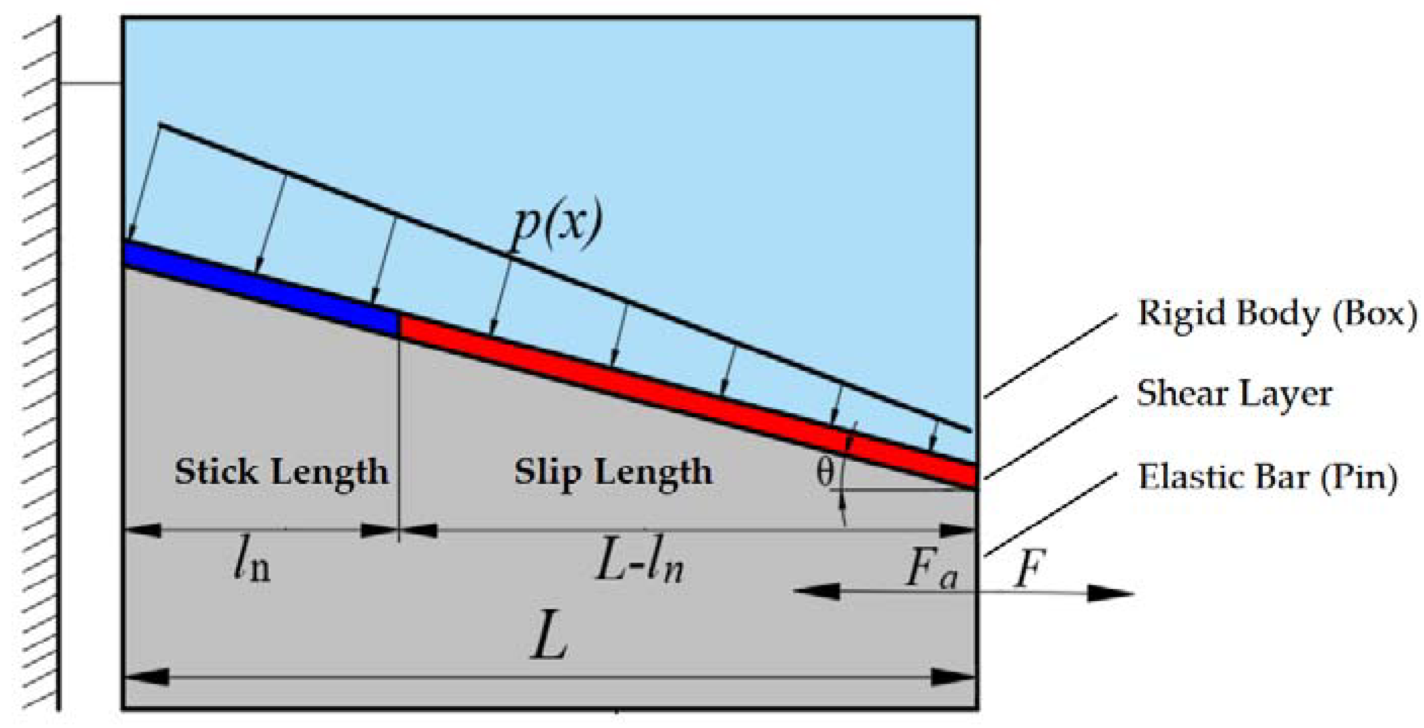
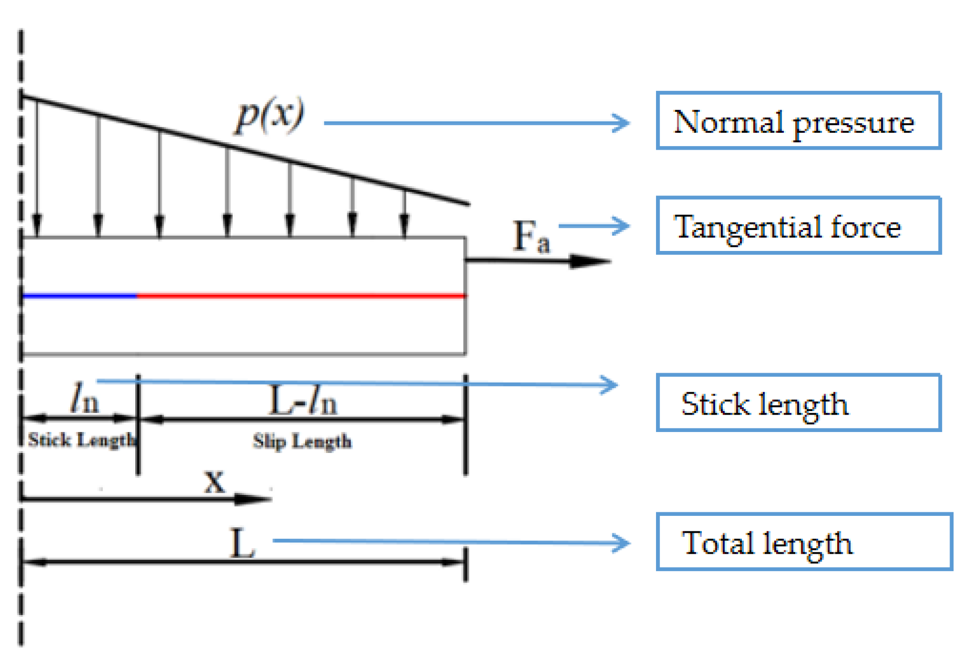
Because of the complex structure of the premium connection, it is difficult to directly measure the microslip process on the sealing surface using experiments. Therefore, the contact behavior on the sealing surface of the premium connection is simplified as a shear layer model, as shown in Figure 4. The model takes into account normal pressures, tangential forces, surface friction coefficients, and the constraints of the torque shoulders and the thread. The physical model of the shear layer consists of an elastic bar, a rigid body, and a shear layer without thickness between the elastic bar and rigid body. Through the tangential force to the right end of the elastic bar, the displacement change of each point in the shear layer model is analyzed. Fa is a thread and shoulder torque binding force, kN, for which the direction is always opposite to the tangential force F. P(x) is the normal pressure generated by the interference fit of the sealing surface when the premium connection is make-up, MPa. The total length of the shear layer is L, mm, the stick length is ln, mm, and the microslip length is L − ln, mm.
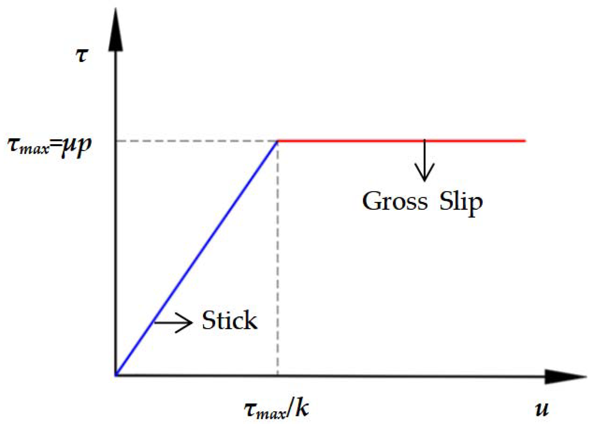
The properties of the shear layer are similar to the ideal elastic–plastic material. Figure 5 shows the force–displacement relationship of the shear layer model without thickness [9]. τ is the shear friction force per unit length, u is the tangential displacement, k is the stiffness per unit length of the shear layer, and τmax (τmax = μp) is the tangential friction force when the elastic bar gross slips. μ and p are the friction coefficient and normal pressure on the sealing surface, respectively. Based on the vibration equilibrium equation of bar [25], the governing equilibrium equations of the stick and microslip regions are obtained as follows:
Stick regions:
E A u x k u ( x ) cos θ = 0
The elastic bar has a constant cross-section area A, mm2, and a uniform Young’s modulus E, GPa.
Microslip regions:
E A u x μ p ( x ) cos θ = 0
Boundary conditions:
E A u 0 = 0 , E A u L = F F a ( L )
When x = ln, the continuity condition is as follows:
u l n = u l n + , u l n = u l n +  
The superscripts + and − denote limiting values from the right and left of x = ln, respectively. The contact surface is subjected to a linearly decreasing pressure [31],
p ( x ) = p 0 k p x
where k is the stiffness per unit length in the shear layer, MPa. P0 is the maximum value of the interface pressure, N/mm. kp is the slope of decreasing pressure.
Figure 5. Relationship between the force and displacement of the shear layer.
Energies 15 08400 g005

2.2. Stick–Microslip Critical Relationship

Using the boundary conditions, the continuity equation of Equations (4) and (5) is used to solve Equations (1) and (2), and the displacements of the elastic bar are obtained as follows [31]:
u ( x ) = μ k p L 2 l n 2 + 2 μ P 0 l n L cos θ + 2 F F a coth ( η l n ) 2 η E A 0 x l n a 1 x 3 + a 2 x 2 + a 3 x + a 4 l n x L
where:
a 1 = μ k p cos θ 6 E A ,   a 2 = μ P 0 cos θ 2 E A , a 3 = μ k p L 2 cos θ 2 μ P 0 L cos θ + 2 F F a 2 E A   a 4 = μ k p L 2 l n 2 + 2 μ P 0 l n L cos θ + 2 F F a coth ( η l n ) 2 η E A μ k p l n 3 + 3 μ p 0 l n 3 6 μ p 0 L l n + 3 μ k p L 2 l n cos θ + 6 l n F F a 6 E A
η = k E A , is a parameter related to the stiffness of the interface shear layer.
According to the stress continuity conditions at the critical point x = ln in the two regions where the stick and microslip occur in the shear layer, the following equation can be obtained:
k u ( l n ) cos θ = μ p ( l n ) + cos θ
Equation (9) describing the nonlinear relationship between the stick length ln and the tangential force F that can be obtained by simultaneously solving Equations (6) and (7):
F = μ P 0 k p l n tanh ( η l n ) η + μ P 0 L l n μ k p L 2 l n 2 2 cos θ + F a
In Equation (8), when ln = L, the minimum tangential force for microslip can be determined as follows:
F min = μ P 0 k p L tanh ( η L ) η cos θ + F a ( L )
When ln = 0, the maximum tangential force for gross slip can be obtained:
F max = μ L cos θ ( p 0 k p L 2 ) + F a ( 0 )

2.3. Force–Displacement Hysteresis Skeleton Curve

When the tangential force increases gradually, the transition between the stick and microslip will occur during the microslip process on the contact surface, which leads to the force–displacement hysteresis of the contact surface. When the elastic bar is subjected to a monotonic tangential force that increases from 0, the relationship curve between the force and displacement is called a hysteretic skeleton curve [32]. As can be seen from Figure 3, the curve is divided into three parts, namely, the linear part, nonlinear part, and constant part. Among them, the linear part is the complete stick segment, for which only elastic deformation occurs in the shear layer without energy dissipation. The nonlinear part is the microslip segment: the two states of stick and slip are converted with the change in tangential force, resulting in energy dissipation. The constant part is gross slip: sliding friction occurs at the contact surface.
By assigning x in Equation (6) to L, the relationship between the tangential force F at the right end of the elastic bar and the displacement u(L) can be obtained:
F = 2 η E A u ( x ) μ k p L 2 l n 2 + 2 μ P 0 l n L cos θ 2 coth ( η l n ) + F a   0 x l n k c u ( x ) + D c l n x L
where:
k c = η E A η L l n + coth ( η l n ) D c = 2 μ k p L 3 3 μ p 0 L 2 + 3 μ k p L 2 l n 2 6 μ p 0 L l n η tanh η l n + μ k p l n 3 3 μ p 0 l n 2 3 μ k p L 2 l n + 6 u p 0 L l n cos θ / 6 L l n + 6 η tanh η l n + F a
When the tangential force at the elastic bar is not enough to cause a microslip, then ln = L. This means the surface is in the complete stick state, so Equation (10) can be simplified as follows:
F = k u u ( L )
where
k u = η E A 2 coth ( η l n ) + F a
From the above equation, it is known that the coefficient ku is related to the stiffness of the interface shear layer and the constraint force of the shoulder, which represents the linear relationship between the tangential force and the displacement at the elastic bar when the contact surface is sticking.
When the tangential force at the elastic bar can cause gross slip, that is ln = 0, Equation (11) can be simplified as:
F = D u
where:
D u = μ L cos θ ( p 0 k p L 2 ) + F a ( 0 )
It can be seen from the Equations (12) and (13) that when the contact surface is in a microslip state, 0 < ln < L, the force–displacement relationship of the contact surface will be affected by the shear layer stiffness and friction coefficient.

2.4. Force–Displacement Hysteresis Curve and Energy Dissipation Equation

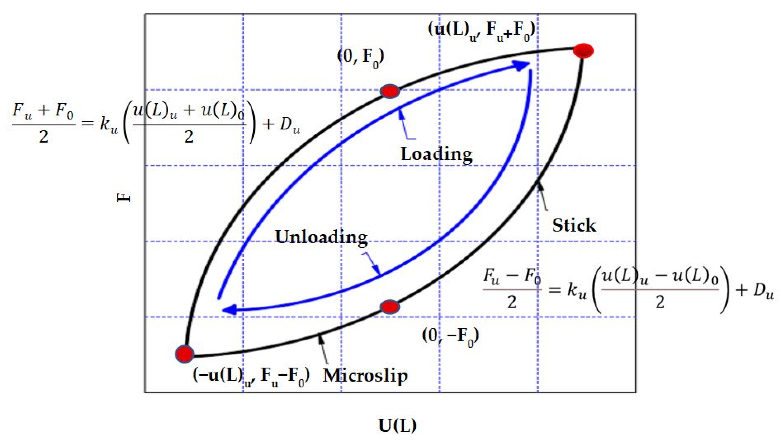
It is easy to obtain the hysteresis curve through the hysteretic skeleton curve, and the energy dissipation of different interface characteristics under the same load can be compared using the area of the hysteresis curve. Figure 6 shows the force–displacement hysteresis curve under the alternating tangential force in one cycle [11]. The area contained in the hysteresis curve is the energy dissipation in one cycle. Through Masing’s hypothesis of the steady-state cyclic hysteresis response, the force–displacement curves during unloading and loading can be derived. The mathematical expression of the unloading process of the elastic bar is as follows:
F u F 0 2 = k u u ( L ) u u ( L ) 0 2 + D u
In this case, F0 and u(L)0 are the initial force and displacement in the unloading process, N, mm, and Fu and u(L)u are the force and displacement in the unloading process, N, mm, respectively. When the unloading is completed, the mathematical expression of the reloading process is as follows:
F u + F 0 2 = k u u ( L ) u + u ( L ) 0 2 + D u
The force–displacement hysteresis curve under the alternating tangential force can be drawn from Equations (18) and (19). Then, the area of the hysteresis curve can be calculated from Equation (20), which is the energy dissipation in per cycle [33],
Δ E D = 4 l n L μ p x u s l x d x = 4 l n L μ p x u x u s t x d x
where ust(x) is the sticking displacement and usl(x) is the microslip displacement, mm.

2.5. Contact Pressure and Contact Length on the Sealing Surface

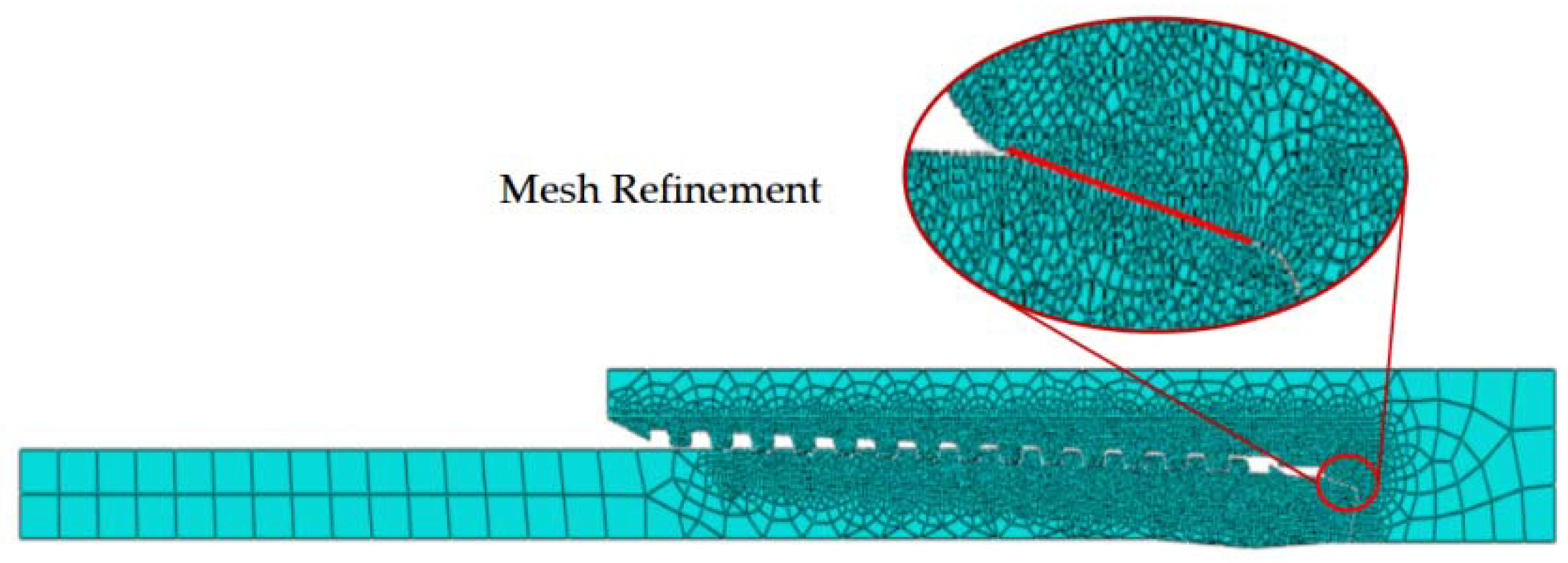
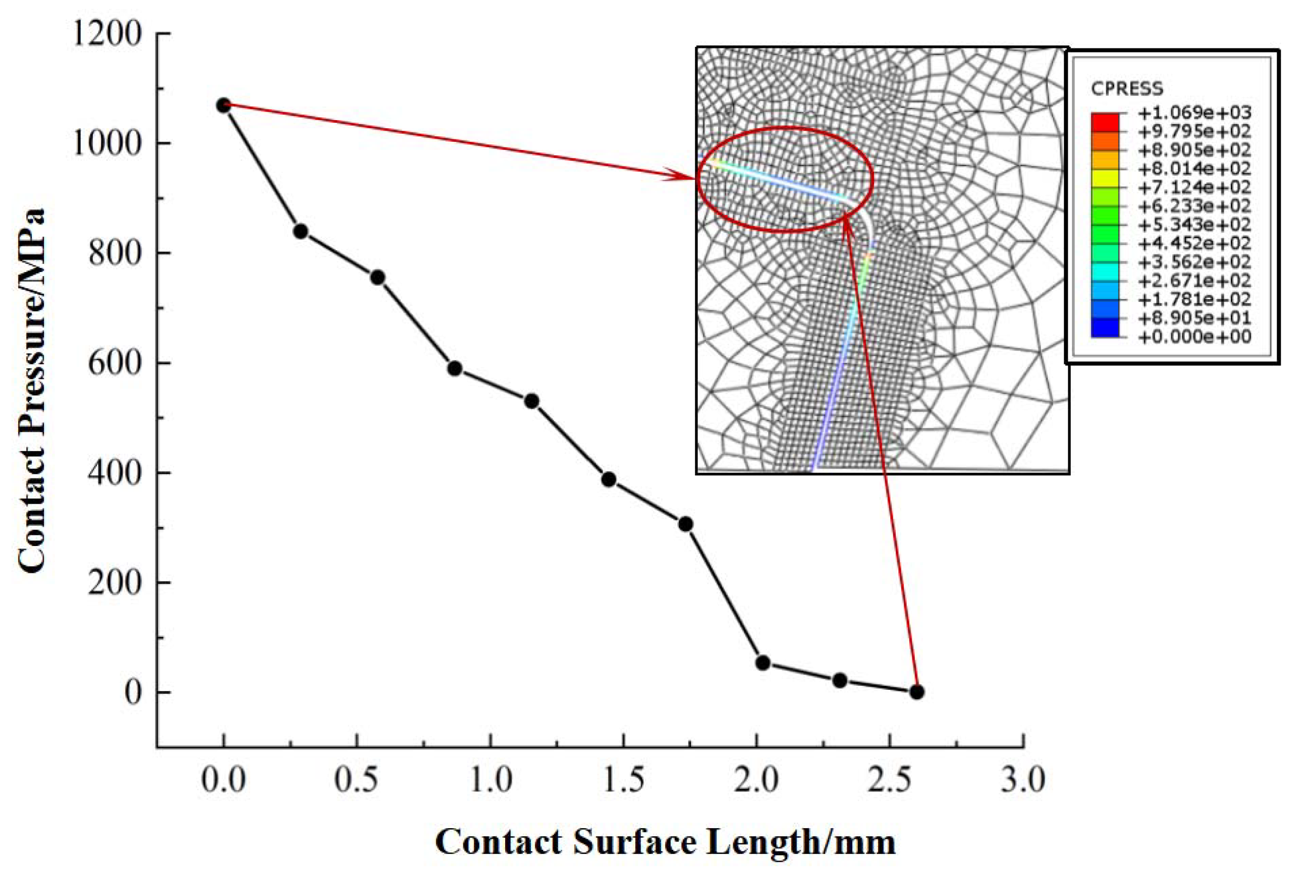
In order to obtain the maximum contact force P0, the pressure distribution slope kp and the contact length L on the sealing surface are used in Equation (6). The Φ88.9 mm × 6.45 mm P110 cone–cone premium connection is used as the research object (parameters shown in Table 1). A finite element model of the premium connection (shown in Figure 7) is established by FEM software ABAQUS, and the contact pressure and contact length distribution diagram are calculated (shown in Figure 8). The elastic modulus of the finite element model is 206 GPa and the Poisson’s ratio is 0.3. According to the contact pair setting criteria, set the sealing surface and shoulder of the coupling to slave surfaces, and set the sealing surface and shoulder of the connection to master surfaces. The mesh at the sealing surface is refined to a size of 10 μm × 10 μm.
It can be seen from Figure 8 that the maximum contact pressure on the sealing surface is 1069 MPa and the contact length L is 2.67 mm. In order to unify the dimensions with Equation (5), the contact pressure is converted to a contact force along the length of the contact surface, so the maximum contact force P0 is 1.3 × 10⁶ N/mm, and the slope of the distribution curve along the length kp is 3.

3. Results

According to Equation (8), the critical length of the stick and microslip on the contact surface is related to the normal pressure p(x), contact length L at the sealing surface, tensile stiffness EA, friction coefficient μ, and stiffness k of shear layer. According to the premium connection’s parameters and the finite element calculation results, E = 206 GPa, A = 26.7 mm2, L = 2.67 mm, p0 = 1.3 × 10⁶ N/mm, and kp = 3, θ = 13.6°. This chapter mainly discusses the influence of the two interface parameters, which are the friction coefficient μ and shear layer stiffness k. Two interface parameters are shown in Table 2.

3.1. Stick–Slip Critical Relationship Analysis

The energy dissipation is caused by the transition between the stick and slip in the microslip process, so the critical tangential force causing the transition should be obtained first. Figure 9 shows the curves of the critical stick–slip length and the critical tangential force under different interface parameters. The abscissa in the figure represents ln, which means the stick length of the contact surface, so the corresponding slip length is L−ln. The ordinate represents the tangential force causing the microslip. When ln = 2.67 mm, the entire contact surface is in a sticking state, and this tangential force is called the minimum microslip tangential force Fmin. If the tangential force continues to increase, the contact surface will change from complete stick to an initial microslip. When 2.67 > ln > 0 mm, the contact surface is in a microslip state where stick and slip coexist. At this time, with the increase in tangential force, the stick length gradually decreases, and the slip length gradually increases. When ln = 0 mm, the stick on the contact surface disappears completely. At this time, the tangential force is called the maximum microslip tangential force Fmax. If the tangential force continues to increase, the contact surface will change from microslip to gross slip.
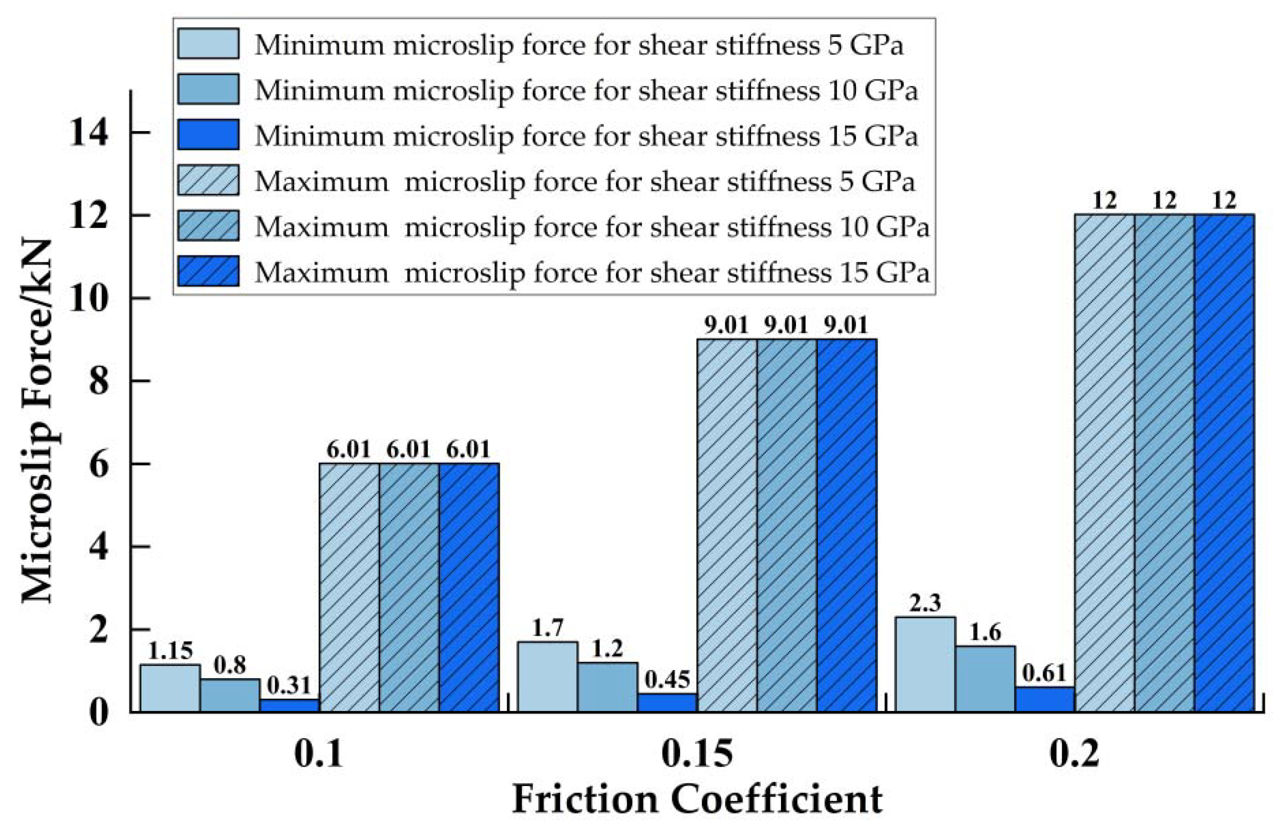
It can be seen from Figure 9 that at the same friction coefficient, the shear layer stiffness only affects the minimum microslip tangential force. With the increase in shear layer stiffness, the minimum microslip tangential force causing the initial microslip decreases, while the maximum microslip tangential force causing the initial gross slip is constant. It seems that the maximum microslip tangential force is equal to the sliding friction force on contact surfaces when the initial gross slip occurs. When the normal pressure and friction coefficient are constant, no matter how the stiffness of the shear layer changes, the sliding friction force is constant, so the maximum microslip tangential force for the initial gross slip is also constant.
The minimum and the maximum microslip tangential force in Figure 9 are used to draw the critical microslip tangential force histogram in Figure 10. It can be seen from the figure that when the friction coefficient is between 0.1 and 0.2, the tangential force causing microslip on the contact surface is 0.31–12 kN. When the friction coefficient is 0.1, the minimum microslip tangential force decreases by 0.42 kN on average when the shear layer increases by 5 GPa. When the friction coefficient is 0.15, the minimum microslip tangential force decreases by 0.63 kN on average when the shear layer increases by 5 GPa. When the friction coefficient is 0.2, the minimum microslip tangential force decreases by 0.85 kN on average when the shear layer increases by 5 GPa. For every 0.05 increase in the friction coefficient, the maximum microslip tangential force increases by 3 kN on average. Under the same shear layer stiffness, the friction coefficient has an effect on both the minimum and maximum microslip tangential forces. With the increase in the friction coefficient, the minimum microslip tangential force causing the initial microslip and the maximum microslip tangential force causing the initial gross slip also increase and they are positively correlated. We confirm that under the same normal pressure, the greater the friction coefficient, the greater the ability of the interface to hinder the microslip, and ultimately the greater the tangential force required.

3.2. Force–Displacement Hysteresis Skeleton Curve Analysis

When the elastic bar is subjected to a unidirectional increasing load, the force–displacement curve at that point is called the hysteretic skeleton curve, which is mainly used for the static nonlinear analysis. Figure 11 shows the force–displacement hysteresis skeleton curves under different interface parameters. In the figure, the abscissa u(L) represents the displacement of the elastic bar under a tangential force, and the ordinate F represents the tangential force causing the displacement. Because of the stick and slip conversion on the contact surface, force–displacement hysteresis occurs at the loading point of the elastic bar, which is manifested as the displacement response, stiffness softening, and energy dissipation of the structure [10]. It can be clearly seen from Figure 11 that the skeleton curve is composed of three parts: linear segment (stick), nonlinear segment (microslip), and horizontal segment (gross slip). Under the same friction coefficient, the slope of the skeleton curve decreases with the increase in tangential force in the microslip part, and the stiffness softening phenomenon occurs. Under the same tangential force, the larger the shear stiffness, the smaller the shear layer deformation, resulting in a decrease in the relative displacement. In the horizontal part of the hysteretic skeleton curve, the maximum microslip tangential force does not change with the shear layer stiffness.
The complete stick displacement and microslip displacement in Figure 11 were extracted, and a histogram of the complete stick displacement and microslip displacement was drawn, as shown in Figure 12. As can be seen from the figure, with the same shear layer stiffness, both the complete stick displacement and the microslip displacement increased with the increase in the friction coefficient, and the proportion of microslip displacement was basically the same. When the friction coefficient was the same, with the increase in shear layer stiffness, the complete stick displacement and microslip displacement decreased, while the proportion of microslip displacement increased (the proportion of microslip displacement was over 90%). We believe that the greater the shear layer stiffness, the smaller the tangential force causing the minimum microslip on the contact surface, and the smaller the microslip displacement, which leads to more easily generating energy dissipation.

3.3. Force–Displacement Hysteresis Curve and Energy Dissipation Analysis

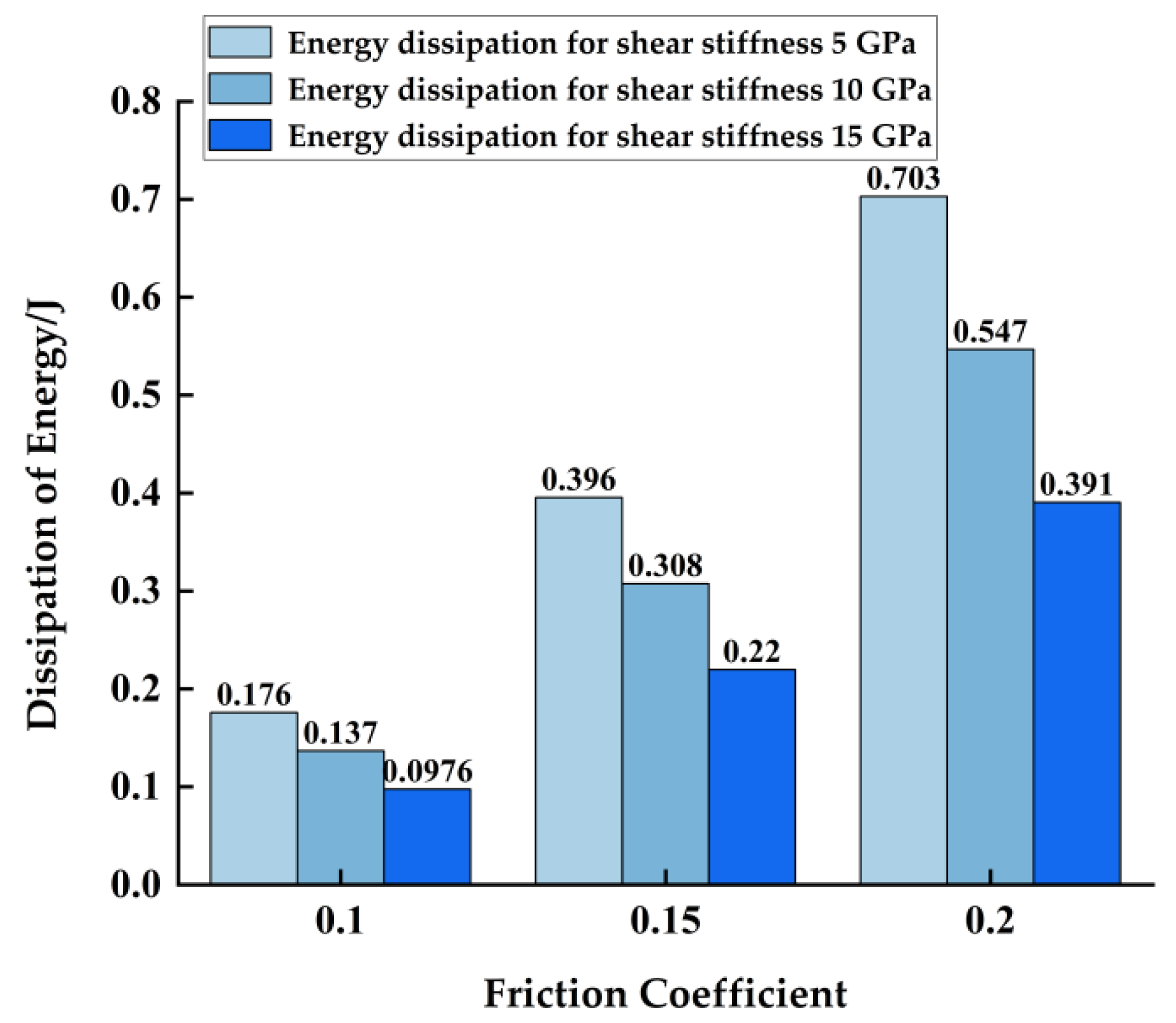
Under alternating loads with amplitude [−Fmax, Fmax], the force–displacement hysteresis curve of the microslip is shown in Figure 13. The curve is an ellipse, and the area contained in it is the energy dissipation in an alternating period. According to the literature [9,10], the elliptic curve is usually formed after a certain number of microslip cycles, and the friction surface undergoes significant plastic deformation, at which time the stiffness will soften. It can be seen from Figure 13 and Figure 14 that under the same friction coefficient, with the increase in shear layer stiffness, the energy dissipation of the contact surface decreased. Under the same shear layer stiffness, with the increase in friction coefficient, the energy dissipation of the contact surface increased. We discovered that the smaller the stiffness of the shear layer, the more severe the plastic deformation of the contact surface, and the worse the stiffness softening phenomenon, resulting in more significant energy dissipation. The larger the friction coefficient, the stronger the ability of the interface to resist slipping, resulting in greater energy dissipation. In addition, the larger the friction coefficient, the greater the energy dissipation.
Because the friction coefficient and the stiffness of the shear layer had different dimensions and orders of magnitude, their influence on energy dissipation was not comparable. In order to compare the influence of these two variables on energy dissipation, standardized regression coefficients were used. The standardized regression coefficient refers to the regression coefficient after eliminating the dimensional influence of the dependent variables and their respective variables, and its absolute value directly reflects the degree of influence of the independent variable on the dependent variable. The standardized linear regression equation is as follows:
y y ¯ s y = β 1 * x 1 x ¯ 1 s x 1 + β 2 * x 2 x ¯ 2 s x 2 + + β n * x n x ¯ n s x n , ( i = 1 , 2 , 3 n )
where y is a dependent variable, y ¯ is the mean of the dependent variable, x i is an independent variable of different dimensions, x ¯ i is the average of the independent variables, s x i is the standard deviation of the independent variable, s y is the standard deviation of the dependent variable, and β i * is the regression coefficient.
Let x1 be the friction coefficient, x2 be the shear layer stiffness, and y be the energy dissipation. Thus, the calculation results indicate that   β 1 * is 0.8848 and β 2 * is −0.4371. This means that the energy dissipation increased by 0.8848 standard units when the friction coefficient increased by 1 standard unit, and the energy dissipation decreased by 0.4371 standard units when the shear layer stiffness increased by 1 standard unit. We put forward that the effect of the friction coefficient on energy dissipation was about two times greater than the shear layer stiffness, and the friction coefficient was positively correlated with energy dissipation and the shear layer stiffness was negatively correlated with energy dissipation.

4. Discussion

From the above research, it can be found that the friction coefficient of the contact surface had a significant effect on the energy dissipation of the sealing surface of the premium connection, while the shear layer stiffness only had an effect on the minimum microslip tangential force of the contact surface. The tangential force discussed in the shear layer model was limited to the initial macro slip. When the tangential force was greater than the force of the critical macro slip, it is necessary to use the Coulomb friction model to recalculate.
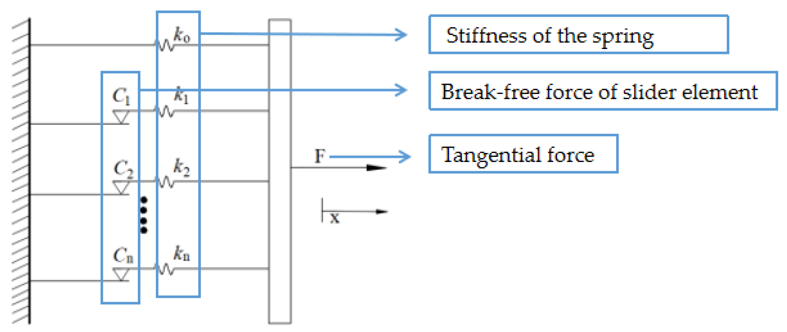
In practice, the energy dissipation of the premium connection is three-dimensional distribution, but the model established in this paper is an idealized one-dimensional model that is simplified. Firstly, the constraints of the tangential displacement at the thread and torque shoulder are simplified, resulting in the neglect of the influence of their elastoplastic deformation in the force–displacement curve. Secondly, the selected shear layer stiffness has limitations, which need to be verified by other methods. In the past research, the thread and the torque shoulder constraints are not involved in energy dissipation of the premium connection. Moreover, in the research on energy dissipation of the bolted connection, the constraint of the bolt is equivalent to a linear spring. However, by applying a tangential binding force on the elastic bar and referring to the study on shear layer stiffness in the literature [23,24], the force–displacement hysteresis curve obtained in this paper can clearly describe the stick and microslip process on the contact surface. At the same time, the energy dissipation of the premium connection can be explained. In addition, compared with the dry friction model [34], as shown in Figure 15, the shear layer model involves a nonlinear relationship between the microslip and tangential force. Compared with the discrete nonlinear Iwan model [9], as shown in Figure 16, the shear layer model is a continuous nonlinear model that is more practical.
The main purpose of this paper is to propose a new method for the energy dissipation analysis of premium connection. This method can be used to analyze the conversion between the stick and microslip, and discuss the influencing factors of energy dissipation on the sealing surface. The energy dissipation of the premium connection is generated when it is subjected to alternating loads, and the friction coefficient is the main factor affecting energy dissipation. In order to reduce the energy dissipation, it is suggested that the metal surface roughness of the premium connections should be reduced during processing, the sealing surface of the premium connections should be protected during transportation to avoid the damage on the sealing surface, and the high temperature resistant thread compound should be applied during the make-up to reduce the friction coefficient on the sealing surface. At the same time, during field operation, the construction parameters should be reasonably controlled, so as to reduce the load variation amplitude caused by the vibration of the string, and also to reduce the energy dissipation of the premium connection.
In future research, more accurate model parameters will be identified through force–displacement experiments of connectors. The shear layer model of the premium connection will be verified and optimized by finite element simulation and experiments, so as to carry out further analysis.

5. Conclusions

In this paper, based on the microslip shear layer model, the vibration equilibrium equation of the premium connection was established under the constraints of the taper of the sealing surface, the thread, and the torque shoulder of the premium connection. Then, the control equilibrium equations of the stick and microslip were derived, and the critical microslip tangential force and force displacement hysteresis curves under different interface parameters were obtained by solving the equilibrium equations. The influence of different interface parameters on the energy dissipation of the premium connection was discussed using the standardized regression coefficient method. The following conclusions were drawn:
(1)
When the tangential force is 0.31–12 kN, the sealing surface of the premium connection will produce energy dissipation caused by the microslip, and when the tangential force is more than 12 kN, the sealing surface will produce energy dissipation caused by the sliding friction.
(2)
The friction coefficient has an effect on both the minimum and maximum microslip tangential forces, while the shear layer stiffness only has an effect on the minimum microslip tangential forces. The greater the shear layer stiffness is, the smaller the minimum microslip tangential force causing the initial microslip is, the smaller the relative displacement of the contact surface is, and the easier it is to cause energy dissipation.
(3)
The influence of the friction coefficient on energy dissipation is two times greater than the shear layer stiffness by standardized regression coefficient analysis. The friction coefficient is positively correlated with energy dissipation, and the shear layer stiffness is negatively correlated with energy dissipation.

Author Contributions

Conceptualization, Y.Y. and Z.Q.; methodology, Y.Y. and Z.Q.; software, Y.Y. and Y.C.; validation, Y.C. and Y.D.; formal analysis, Y.Y.; investigation, Y.Y.; resources, Y.Y.; data curation, Y.Y.; writing—original draft preparation, Y.Y.; writing—review and editing, Y.Y., Z.Q., Y.C. and Y.D.; visualization, Y.Y.; supervision, Z.Q. and Y.D.; project administration, Y.Y.; funding acquisition, Z.Q. and Y.D. All authors have read and agreed to the published version of the manuscript.

Funding

This research was funded by the National Natural Science Foundation of China (NSFC) (nos. 52274006 and 51974246), and the Innovative Talent Promotion Program “Young Science and Technology Star Project” of Shaanxi Province of China (no. 2021KJXX-40).

Data Availability Statement

The data presented in this study are available upon request from the corresponding author.

Conflicts of Interest

The authors declare no conflict of interest.

Nomenclature

Notation
EYoung’s modulus, GPa
Aconstant cross-section area of the elastic bar, mm2
τshear friction force per unit length, N
utangential displacement, mm
kstiffness per unit length of the shear layer, GPa
μfriction coefficient
pnormal pressure on the sealing surface, MPa
P0the maximum value of a contact force along the length, N/mm
kpslope of decreasing pressure
Fathread and shoulder torque binding force, kN
Fshear force, kN
ΔEDenergy dissipation in per cycle, J
lnstick length, mm
uststicking displacement, mm
uslmicroslip displacement, mm
ydependent variable
y ¯ mean of the dependent variable
xiindependent variables of different dimensions
x ¯ i average of the independent variables
s x i standard deviation of the independent variable
s y standard deviation of the dependent variable
β i * regression coefficient

References

  1. ISO 13679; Petroleum and Natural Gas Industries -Procedures for Testing Casing and Tubing Connection. International Organization for Standardization: Geneva, Switzerland, 2002.
  2. Chen, W.; Deng, X. Structural damping caused by micro-slip along frictional interfaces. Int. J. Mech. Sci. 2005, 47, 1191–1211. [Google Scholar] [CrossRef]
  3. Kogut, L.; Etsion, I. Elastic-plastic contact analysis of a sphere and a rigid flat. J. Appl. Mech. 2002, 69, 657–662. [Google Scholar] [CrossRef] [Green Version]
  4. Jackson, R.L.; Green, I. A finite element study of elasto-plastic hemispherical contact against a rigid flat. J. Trib. 2005, 127, 343–354. [Google Scholar] [CrossRef] [Green Version]
  5. Lin, L.P.; Lin, J.F. An elastoplastic microasperity contact model for metallic materials. J. Trib. 2005, 127, 666–672. [Google Scholar]
  6. Chung, J.C.; Lin, J.F. Variation in fractal properties and non-Gaussian distributions of microcontact between elastic-plastic rough surfaces with mean surface separation. J. Appl. Mech. 2006, 73, 143–152. [Google Scholar] [CrossRef]
  7. Xueliang, Z.; Nanshan, W.; Suhua, W. Elastoplastic fractal model for tangential contact damping energy dissipation of machine joint interfaces. J. Mech. Eng. 2013, 49, 43–49. [Google Scholar]
  8. Huang, W.; Gao, D.; Liu, Y. Inter-helical and intra-helical buckling analyses of tubular strings with connectors in horizontal wellbores. J. Pet. Sci. Eng. 2017, 152, 182–192. [Google Scholar] [CrossRef] [Green Version]
  9. Segalman, D.J. A Four-Parameter Iwan Model for Lap-Type Joints. J. Appl. Mech 2005, 72, 752–760. [Google Scholar] [CrossRef] [Green Version]
  10. Fujimoto, T.; Kagami, J.; Kawaguchi, T.; Hatazawa, T. Micro-displacement characteristics under tangential force. Wear 2000, 241, 136–142. [Google Scholar] [CrossRef]
  11. Wang, D.; Zhang, Z. A four-parameter model for nonlinear stiffness of a bolted joint with non-Gaussian surfaces. Acta Mech. 2020, 231, 1963–1976. [Google Scholar] [CrossRef]
  12. Oldfield, M.; Ojyang, H.; Mottershead, J. Experimental study and analytical modelling of a bolted joint subjected to harmonic excitation. Shock. Vib. Dig. 2006, 38, 246–247. [Google Scholar]
  13. Mahmoudi, M.; Kosari, M.; Lorestani, M.; Jalili Sadr Abad, M. Effect of contact surface type on the slip resistance in bolted connections. J. Constr. Steel Res. 2020, 166, 105943. [Google Scholar] [CrossRef]
  14. Xu, W.; Liu, Z.; Cheng, Q.; Chen, H.; Zhao, Y.; Li, Y. A mathematical model of a bolted connection based on Florida contact theory to study the influence of the friction coefficient on structural performance. Adv. Mech. Eng. 2019, 11, 1687814019851398. [Google Scholar] [CrossRef]
  15. Iwan, W.D. On a Class of Models for the Yielding Behavior of Continuous and Composite Systems. J. Appl. Mech. 1967, 34, 612–617. [Google Scholar] [CrossRef]
  16. Iwan, W.D. A Distributed-Element Model for Hysteresis and Its Steady-State Dynamic Response. J. Appl. Mech. 1966, 33, 893. [Google Scholar] [CrossRef]
  17. Segalman, D.J. An Initial Overview of Iwan Modeling for Mechanical Joints; Sandia National Lab. (SNL-NM): Albuquerque, NM, USA, 2001. [Google Scholar]
  18. Yang, B.D.; Chu, M.L.; Menq, C.H. Stick–slip–separation analysis and non-linear stiffness and damping characterization of friction contacts having variable normal load. J. Sound Vib. 1998, 210, 461–481. [Google Scholar] [CrossRef]
  19. Wang, Y.; Qian, C.; Kong, L.; Zhou, Q.; Gong, J. Design optimization for the thin-walled joint thread of a coring tool used for deep boreholes. Appl. Sci. 2020, 10, 2669. [Google Scholar] [CrossRef] [Green Version]
  20. Li, D.; Li, Y.; Chen, J.; Masoumi, H. An analytical model for axial performance of rock bolts under constant confining pressure based on continuously yielding criterion. Tunn. Undergr. Space Technol. 2021, 113, 103955. [Google Scholar] [CrossRef]
  21. Ju, B.-S.; Jeon, B.-G.; Kim, S.-W.; Son, H.-Y. Validation of Seismic Performance of Stainless Press-to-Connect Piping System under Cyclic Loadings. Appl. Sci. 2022, 12, 3896. [Google Scholar] [CrossRef]
  22. Qin, Z.; Cui, D.; Yan, S.; Chu, F. Hysteresis modeling of clamp band joint with macro-slip. Mech. Syst. Signal Process. 2016, 66–67, 89–110. [Google Scholar] [CrossRef]
  23. Oldfield, M.; Ouyang, H.; Mottershead, J.E. Simplified models of bolted joints under harmonic loading. Comput. Struct. 2005, 84, 25–33. [Google Scholar] [CrossRef]
  24. Majumdar, A.; Bhushan, B. Fractal Model of Elastic-Plastic Contact Between Rough Surfaces. J. Tribol. 1991, 113, 1–11. [Google Scholar] [CrossRef]
  25. Charalampakis, A.E.; Koumousis, V.K. A Bouc–Wen model compatible with plasticity postulates. J. Sound Vib. 2009, 322, 954–968. [Google Scholar] [CrossRef]
  26. Zaman, M.A.; Sikder, U. Bouc–Wen hysteresis model identification using Modified Firefly Algorithm. J. Magn. Magn. Mater. 2015, 395, 229–233. [Google Scholar] [CrossRef]
  27. Pereira Miguel, L.; Oliveira Teloli, R.d.; Silva, S.d. Harmonic Balance of Bouc-Wen Model to Identify Hysteresis Effects in Bolted Joints. In Vibration Engineering and Technology of Machinery; Springer: Cham, Switzerland, 2021; pp. 65–79. [Google Scholar]
  28. Shetty, D.; Allen, M.S.; Schoneman, J.D. Application of the Bouc-Wen Model to Bolted Joint Dynamics. In Nonlinear Structures & Systems; Springer: Cham, Switzerland, 2021; Volume 1, pp. 35–38. [Google Scholar]
  29. Peng, Z.; Zhou, C.G. Modeling of Nonlinear Isolation System Based on the Bouc–Wen Differential Model. Strength Mater. 2017, 49, 206–211. [Google Scholar] [CrossRef]
  30. Menq, C.H.; Bielak, J.; Griffin, J.H. The influence of microslip on vibratory response, part I: A new microslip model. J. Sound Vib. 1986, 107, 279–293. [Google Scholar] [CrossRef]
  31. Sun, D. Study on Energy Dissipation Mechanism and Prediction of Bolted Joints Structure. Ph.D. Thesis, Beijing Institute of Technology, Beijing, China, 2016. [Google Scholar]
  32. Segalman, D.J. Modelling joint friction in structural dynamics. Struct. Control. Health Monit. 2006, 13, 430–453. [Google Scholar] [CrossRef]
  33. Sun, D.; Liao, R. Investigation into the Effect of Interface Characteristics on the Energy Dissipation of the Bolted Joints. J. Comput. Theor. Nanosci. 2015, 12, 2821–2829. [Google Scholar] [CrossRef]
  34. Song, Y.; McFarland, D.M.; Bergman, L.A.; Vakakis, A.F. Effect of pressure distribution on energy dissipation in a mechanical lap joint. AIAA J. 2005, 43, 420–425. [Google Scholar] [CrossRef]
Figure 1. Schematic diagram of premium connections of a tubing string.
Energies 15 08400 g001
Figure 2. Schematic diagram of premium connection.
Energies 15 08400 g002
Figure 3. Force–displacement relation curve for the premium connection.
Energies 15 08400 g003
Figure 4. Shear layer model of the sealing face of the premium connection.
Energies 15 08400 g004
Figure 6. Force–displacement hysteresis curve.
Energies 15 08400 g006
Figure 7. Finite element model of premium connection.
Energies 15 08400 g007
Figure 8. Contact pressure and contact length distribution on the sealing surface.
Energies 15 08400 g008
Figure 9. Stick–slip critical length and critical force curve.
Energies 15 08400 g009
Figure 10. Critical microslip tangential force histogram.
Energies 15 08400 g010
Figure 11. Force–displacement hysteresis skeleton curve.
Energies 15 08400 g011
Figure 12. Histogram of stick displacement and microslip displacement.
Energies 15 08400 g012
Figure 13. Force-displacement hysteresis curve.
Energies 15 08400 g013
Figure 14. Histogram of the energy dissipation.
Energies 15 08400 g014
Figure 15. Dry friction model.
Energies 15 08400 g015
Figure 16. Iwan model.
Energies 15 08400 g016
Table 1. Design parameters of the premium connection.
Sealing TaperSeal InterferenceShoulder AngleThread TaperPitch
1/20.176 MM−15°1/24.234 mm
Table 2. Interface parameters.
The Coefficient of Friction Shear Layer Stiffness
0.105 GPa
0.1510 GPa
0.2015 GPa
Publisher’s Note: MDPI stays neutral with regard to jurisdictional claims in published maps and institutional affiliations.