Abstract
According to the requirements of weak current measurement in power grid, a weak current sensor with anti-low frequency interference ability is developed. The sensor adopts the principle of fluxgate detection and adds a magnetic ring on the original basis. The structure of the magnetic ring is simulated using comsol to further improve detection sensitivity. In order to solve the problem that the electromagnetic current sensor is vulnerable to the interference of geomagnetic field and power frequency magnetic field in weak current measurement, a magnetic shielding method with low cost is selected, and the shielding shell structure is designed using a finite element analysis method. The experimental results show that the minimum measurable current is 1 mA, the measurement range is 1 mA–1 A, and the bandwidth is DC-16 kHz. The designed magnetic shielding shell can effectively reduce 97.3% of the DC magnetic field interference and 95.7% of the power frequency magnetic field interference. The sensor can realize accurate measurement of weak current in power grid.
1. Introduction
Current is an important physical quantity in the power system, and the accurate measurement of current is of great significance to equipment condition monitoring, fault detection and location, and power flow control [1]. For complicated application scenarios, different sensors need to be selected for measurement. Weak currents in the power grid mainly include leakage currents of high-voltage bushings, insulators and lightning arresters, which can reflect the insulation status of the equipment. The amplitude of the leakage current is hard to detect, typically valued at a few mA to a hundred mA [2].
Compared with various voltage measurement methods, the main methods currently used for current measurement include the following: shunt resistors, current transformers, Roche coils, Hall current sensors, fluxgate current sensors, and giant magnetoresistive sensors [3,4], each of which has its own drawbacks [5,6]. Compared to other detection methods, fluxgate current sensors are one of the most accurate ways to measure current today. Its resolution to magnetic field can reach 0.1 nT, accuracy can reach 0.26%, and stability can reach 0.4% [7], which is widely used in AC and DC small current measurements. Among them, the literature [8,9] designed an AC–DC residual current detection sensor capable of detecting AC–DC residual currents above 5 mA using the fluxgate technique. In [10], a current sensor based on fluxgate technique is proposed for measuring nonlinear currents of arbitrary waveforms and linear currents from DC to several kilohertz. However, in practical measurements, this current sensor based on weak magnetic field detection is highly susceptible to external magnetic field interference [11,12,13], which is not considered in the above literature. In order to resist the external magnetic field interference, a lot of research has been conducted by domestic and foreign scholars, among which some references [14,15,16] proposed a circular array to improve measurement accuracy and reduce external interference, and experimentally proved the suppression effect of this method on the external magnetic field. However, this method is large in size and its cost is high, which makes it difficult to be applied practically. Reference [17] added a U-shaped shield outside the fluxgate sensor to shield the external magnetic field interference, but it failed to analyze the material and structure of the shield. This paper shows that a magnetic shielding method is feasible, but it does not describe more details. According to the simulation results, the annular magnetic shielding shell has a better shielding effect. Therefore, the annular magnetic shielding method is studied in this paper.
Based on the above reasons, this paper develops a fluxgate weak current sensor with the ability to resist low-frequency interference. To realize the weak current measurement, a fluxgate sensor with high sensitivity is selected, a poly-magnetic ring is additionally added outside it, and the finite element method is used to design the magnetic ring structure to improve the sensor’s detection sensitivity. To resist the external magnetic field interference, a magnetic shielding housing is designed to realize the accurate measurement of weak current.
2. The Overall Structure and Principle of the Sensor
2.1. Fluxgate Current Sensor Structure
The structure of the fluxgate current sensor designed in this paper is shown in Figure 1. The sensor is mainly composed of four parts: a toroidal magnetic ring, a fluxgate chip, a signal processing circuit, and a magnetic shielding shell. The magnetic field generated by the measured current is amplified by the magnetic concentrating ring, measured by the fluxgate chip at the magnetic ring air gap and converted into a voltage signal, and then, through the low-pass filter and the amplification circuit, the final output is obtained. In order to shield it from the interference of external magnetic field, a shielding shell is added outside.
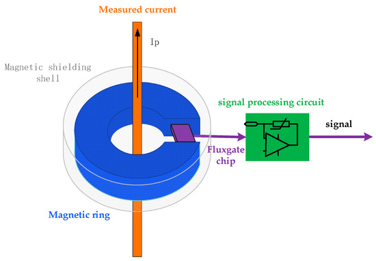
Figure 1.
Fluxgate current sensor structure.
2.2. Principle of Fluxgate Detection Current
Figure 2 shows the basic principle of a single-core fluxgate sensor [18], in which the magnetic core is a soft magnetic material, and an excitation coil and an induction coil are wound on it.
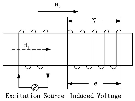
Figure 2.
Single-core fluxgate sensor structure.
The magnetic field generated by the excitation source is calculated as follows:
where is the angular frequency of the excitation source. The magnetic induction intensity inside the core is calculated as follows:
where is the magnetic permeability of the core. When is greater than the magnetic saturation strength of the core, the hysteresis line of the core is not linear and its permeability changes periodically, at which time the permeability is expressed by μ(t), and the voltage across the induction coil is based on the following equation:
where N is the number of turns of the induction coil and S is the cross-sectional area of the magnetic core. Since the magnetic permeability is constantly greater than 0, μ(t) is an even function, and μ(t) is expanded by the Fourier series to obtain its value based on the following equation:
where is the constant component of μ(t), and μ(t),, , is the amplitude of each harmonic component of μ(t). Substituting Equation (4) into Equation (3), we can obtain the following formula:
It can be seen from the formula that the induced electromotive force generated by the excitation magnetic field is the odd harmonic of the excitation frequency, and there is no even component. When considering the magnetic field H0 outside the magnetic core, the coil induced voltage is based on the following equation:
When is much smaller than the core saturation strength and the excitation field , the effect of on μ(t) can be neglected. The first two terms of the above equation are the same as the equation. The third term is the change in induced electric potential caused by the external magnetic field , which is based on the following equation:
It can be seen from Equation (7) that, when there is an external magnetic field, the even-order harmonic component of the excitation frequency will be generated in the induction coil. Usually, the second harmonic component of the induction voltage is amplified by frequency selection so as to calculate the value of the external magnetic field.
When using the fluxgate principle to measure current, the detection schematic is shown in Figure 3. The current in the measured wire is . According to the Biot’s law, the external magnetic field detected by the fluxgate sensor is based on the following formula:
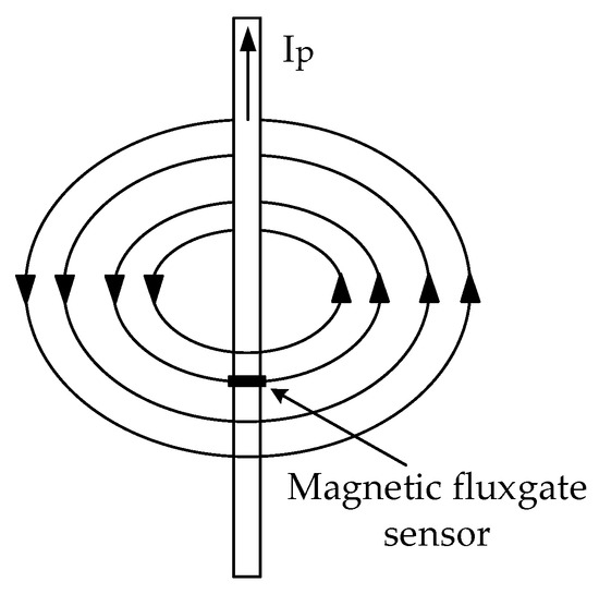
Figure 3.
Fluxgate current measurement schematic.
In the formula, μ is the permeability of the space where the wire is located, and r is the distance between the fluxgate sensor and the measured wire. According to the above relationship, the measured current Ip can be calculated.
3. Sensor Design
3.1. FluxGate Chip Selection
In order to detect small currents, the fluxgate sensing chip used should have the characteristics of high sensitivity and low noise. Among the commercially produced chips, the DRV425 fluxgate magnetic field sensor of TI company is selected. Its bandwidth is DC-47 khz, the measurement range of magnetic induction intensity is ±2 mT, and the sensitivity range is 480–1440 mV/mT. It has the characteristics of low offset, low drift and low noise.
According to the Biot–Savart law, the sensitivity of DRV425 is 0.192–0.576 V/A when it is installed 5 cm away from the measured wire, which cannot meet the requirements of 1 mA small current measurement. Therefore, a magnetic ring is added to improve the sensitivity of the sensor.
3.2. Magnetic Ring Material Selection
Table 1 shows the performance parameters of several common magnetic materials. It can be seen from the table that permalloy has the highest permeability and the lowest coercivity. Therefore, permalloy is selected as the magnetic ring material of the sensor.

Table 1.
Transformer quality and its definition.
3.3. Simulation Analysis of the Magnetic Ring Structure
The function of multiple magnetic cores is to increase the magnetic flux density and improve the sensitivity of the sensor. According to the distribution characteristics of the measured magnetic field, choosing an annular magnetic core is more conducive to reducing the reluctance [19]. In order to analyze the effect of increasing the magnetic ring on the sensor, the gain effect of the ring is analyzed in this paper using theoretical analysis and a finite element simulation software, which simulates the size of the ring, the size of the opening, and the placement of the magnetic field sensor. Figure 4a shows the 3D model of the sensor, which includes the current conductor, the magnetic ring and the fluxgate chip, and (b) shows the flux density distribution cloud.
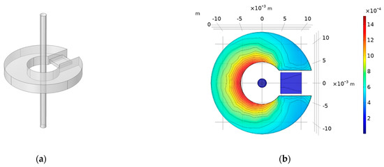
Figure 4.
Simulation diagram of the magnetic ring structure: (a) simulation model, and (b) magnetic flux density distribution cloud map.
The simulation in the figure applies 10 A current to the model. It can be found from the magnetic flux distribution density diagram in Figure 4b that, although the magnetic flux at the fluxgate chip is still less than that in the magnetic core, the introduction of the magnetic core has greatly improved the magnetic flux at the fluxgate chip. In order to make the magnetic induction intensity at the air gap of the magnetic ring as large as possible, the size and air gap width of the ring should be as small as possible while ensuring that it can be put into the tunneling reluctance sensing chip [20], so the opening width of the magnetic ring is set to 6 mm. When the equivalent distance between the magnetic ring and the wire is smaller, the magnetic field gain effect is more obvious; thus, the inner diameter of the magnetic ring should be as small as possible. Considering the size of the conductor to be measured, the inner diameter of the ring is selected as 10 mm. Figure 5 shows the variation in the average magnetic induction intensity when the core height, outer diameter and fluxgate chip mounting position are changed while other conditions are fixed.
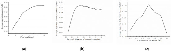
Figure 5.
Change in the average magnetic induction intensity with core structure: (a) variation in core height; (b) variation in outer diameter of magnetic ring; and (c) change in the installation height of the fluxgate chip.
According to the simulation results, the height of the magnetic ring is 8 mm, the outer diameter is 23 mm, and the fluxgate chip is installed at 1/2 height of the magnetic ring.
3.4. Simulation Analysis of Magnetic Shielding
In the classification of electromagnetic shielding, the electromagnetic shielding problem belongs to passive shielding. The main method of shielding low-frequency magnetic field is to use a high-permeability material shell for magnetic shielding. For the low-frequency magnetic shielding effect, the shielding effectiveness (SE) is [21]:
Among them, is the initial permeability, S is the thickness of the shielding magnet, and is the equivalent spherical radius of the same volume as the shielding magnet. The magnetic shielding effect is positively correlated with the permeability of the shielding material and the size and thickness of the shielding shell. Therefore, permalloy with high permeability is selected as the magnetic shielding material, and 0.2 mm of the shielding material is selected with an existing thickness of 0.05 mm, 0.1 mm and 0.2 mm.
Under conditions of the same thickness and similar size, the overall performance of the spherical shell is the best. Second are the cylindrical shell and the ellipsoidal shell. The performance of the square shell is the worst. Considering the difficulty of spherical shell processing, a relatively simple cylindrical shell with better performance is selected. According to the above conditions, the simulation model is established as shown in Figure 6a, and the shielding shell is added on the basis of Figure 4. Figure 6b is the magnetic field distribution cloud map after adding magnetic field in the external space.
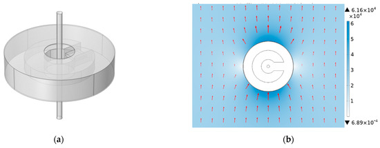
Figure 6.
Shielding shell simulation: (a) simulation model, and (b) cloud map of the magnetic field distribution.
Since the introduction of magnetic shielding will reduce the magnetic gathering effect of the magnetic core, the structural design of the magnetic shielding needs to be comprehensively considered to reduce the negative impact of the magnetic shielding on the measurement. Figure 7 shows the variation trend of magnetic shielding effectiveness (SE) by changing the radius and height of the shielding shell under the external magnetic field through finite element simulation. The simulation shows that the electric field generated is much stronger than the sensor chip offset under 10 A. According to the calculation, even under the condition of 1 mA, the generated source field strength is about 39.6 nT, which still meets the long-term measurement requirements of the sensor. Figure 7a shows the variation trend of shielding effectiveness with external diameter; Figure 7b shows the variation trend of shielding effectiveness with height.
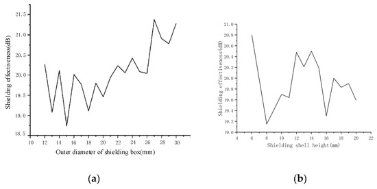
Figure 7.
Curve of shielding effectiveness of the shielding enclosure varying with size: (a) variation in shielding shell outer diameter, and (b) variation in shielding shell height.
The simulation results show that the shielding effectiveness increases with an increase in the equivalent radius of the shielding shell. When the outer diameter of the shielding shell increases to 18 mm, the shielding effectiveness reaches 20.81 dB. When the outer diameter increases to 30 mm, the shielding effectiveness only increases by 0.9 dB, so the outer diameter of the shielding shell is 18 mm. When the outer diameter of the shielding shell increases to 9 mm, the shielding effectiveness reaches 19.53 dB. Since excessive size will reduce the practicability and portability of the device, and will interfere with the magnetic concentration of the magnetic core, the outer diameter of the shielding shell is 18 mm and the height is 9 mm in order to obtain the device with the best comprehensive performance.
3.5. Filter Amplification Circuit Design
In order to reduce the interference of high-frequency components, a filter circuit is added at the back end of the sensor to filter out high-frequency interference signals. The filter circuit uses a second-order Butterworth low-pass filter as shown in Figure 8, where R1–R3 are high-precision resistors, C1 and C2 are high-frequency capacitors, and AMP is an instrument amplifier (MCP6004).
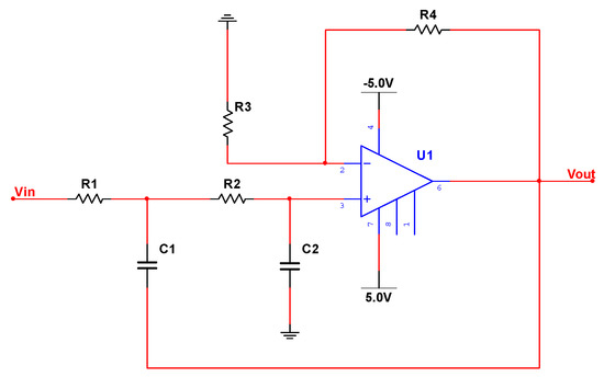
Figure 8.
Two-order low-pass filter circuit.
The objective of this paper is residual current detection. The cut-off frequency of the low-pass filter is set to 20 kHz, and the passband amplification factor is 1.5 times. The relevant parameters are calculated as follows: R1 = 6.2 kΩ, R2 = 6.2 kΩ, R3 = 10 kΩ, R4 = 5.1 kΩ, C1 = 1 nF, and C2 = 1 nF. The frequency response curve of the filter circuit is shown in Figure 9.
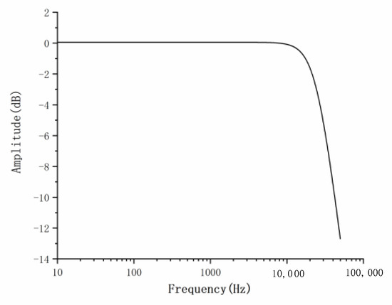
Figure 9.
Amplitude–frequency response characteristics of the filter circuit.
4. Test of Sensor Performance Parameters
Based on the above analysis, a prototype of a small current sensor based on the fluxgate principle was made, as shown in Figure 10. In order to verify the parameters of the sensor, an experimental platform was built to test the performance of the sensor.
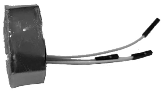
Figure 10.
Prototype sensor.
4.1. Experimental System
The experimental system established is shown in Figure 11. The signal generator is connected to the power amplifier, and the power amplifier output is connected to the current-limiting resistor to generate the current signal. The current-carrying conductor is passed through the middle of the fluxgate ring, and the output of the sensor is connected to an oscilloscope. At the same time, the voltage across the resistor is collected with a voltage probe, and the current in the conductor is calculated from the voltage and compared with the output of the sensor.
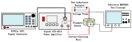
Figure 11.
Experimental system.
Among them, the signal generator is NI PXIe 1071; the bandwidth is DC-2 GHz; the power amplifier is Aigtek ATA-4014; the bandwidth is DC-1 MHz; the maximum output power is 452 W; the maximum output current is 4 A; the current-limiting resistance is 50 Ω inductanceless resistance. The oscilloscope uses Tektronix MSO3024, the bandwidth is DC-200 MHz, and the sampling rate is 2.5 GS/s. For the 8-Bit Four-Channel Digital Oscilloscope, the voltage probe is Tektronix P2220, the bandwidth is DC-100 MHz, and the maximum input voltage amplitude is 300 V.
4.2. Minimum Measurable Current
To determine the minimum measurable current value of the sensor, the output waveforms of the sensor at 1 mA, 2 mA, 3 mA, 4 mA, and 5 mA were measured respectively, and the results are shown in Figure 12. In the figure, the black curve is the current waveform converted from the voltage measured at both ends of the non-inductive resistor, and the blue curve is the sensor output waveform.
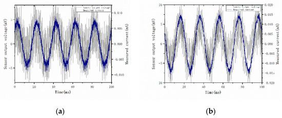
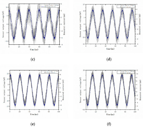
Figure 12.
Output waveform at different currents: (a) 1 mA; (b) 2 mA; (c) 3 mA; (d) 4 mA; (e) 5 mA; and (f) 6 mA.
As can be seen from the figure, the designed sensor can measure the mA level current very well. As the current amplitude increases, the output voltage trace becomes clearer, and the noise causes less impact on the sensor. The absolute value of the error of the output value of each sensor at different currents of <5% is used as the basis for determining the minimum measurable current [22]. To further determine the DC measurement capability and the bandwidth range of the sensor, the platform, as shown in Figure 11, is used to measure the waveform and the rise time of the square-wave signal under the condition of 1 mA DC. The results are shown in Figure 13.
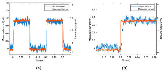
Figure 13.
Output waveform at 1 mA DC square wave: (a) output waveform, and (b) details of the output waveform.
The blue line in the figure is the sensor output, and the red line is the current value calculated at both ends of the non-inductive resistor. It can be seen that, under the condition of 1 mA, the sensor can still achieve a good function despite some interference. The sensor bandwidth BW can be calculated using the following Equation (10):
where t is the rise time. The measured rise time of the sensor is about 23 μs. The bandwidth is about 15.3 kHz. It can be seen that the sensor maintains good stability and accuracy under 1 mA, basically meeting the requirements of 16 kHz bandwidth measurement. Section 4.4 will further discuss bandwidth.
Based on the sensitivity obtained from the later fitting as a benchmark, the sensitivity of the sensor at different currents is calculated from the 50 Hz component amplitude of the output current waveform at different currents, as shown in Figure 14. In the figure, the solid line is the sensor sensitivity, the dashed line is the sensitivity ±5% error line, and the dot is the sensor sensitivity corresponding to the measured current.
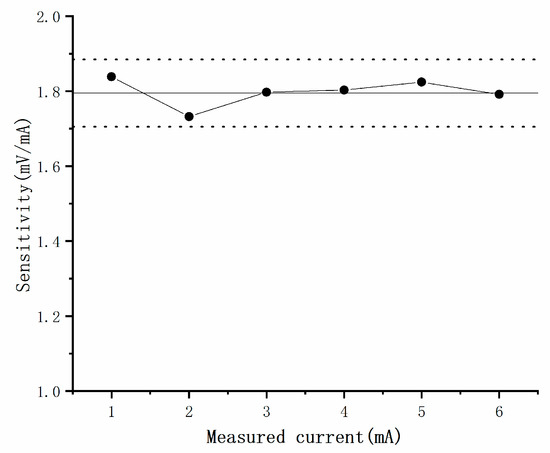
Figure 14.
Variation curve of sensor sensitivity.
It can be seen from the figure that the sensitivity at 1 mA–6 mA is within ±5% of the sensor sensitivity. According to the above criteria, the sensor can achieve accurate measurement at 1 mA current.
4.3. Range, Sensitivity and Linearity
The static characteristics of the sensor were also calibrated using the test platform shown in Figure 11, and the input and output curves of the sensor were tested at DC and 50 Hz measured currents, respectively. Due to the power supply voltage limit of the fluxgate chip, the output waveform is distorted when the measurement current is increased to 1 A, so the sensor is calibrated only in the range of 0–1 A. The input and output curves of the sensor at DC and 50 Hz are shown in Figure 15.
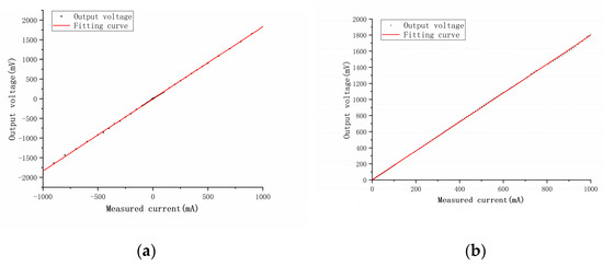
Figure 15.
Input and output curves at DC and 50 Hz: (a) output curve at DC, and (b) output curve at 50 Hz.
In the figure, the black point is the actual output voltage of the sensor, and the straight line is the fitting curve. It can be seen from the figure that the output of the sensor is linear in the range of 0–1 A, and the linearity is 99.96% at DC and 99.98% at 50 Hz. Therefore, it can be explained that the range of the sensor is −1 A–1 A in DC and 0–1 A at 50 Hz, and the sensitivity is 1.83592 V/A at DC and 1.796 V/A at 50 Hz.
4.4. Sensor Bandwidth
The frequency characteristics of the sensor were tested. The measured current was set to 100 mArms, and the output frequency of the power amplifier was adjusted to DC ~20 kHz. The frequency response characteristics of the sensor are shown in Figure 16. It can be seen from the figure that the frequency is about 16 kHz when the amplitude attenuation is −3 dB, so the frequency range of the sensor can be determined to be DC-16 kHz.
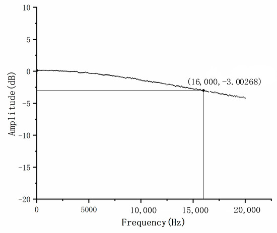
Figure 16.
Sensor frequency response characteristics.
4.5. Anti-Jamming Capability
The platform of sensor anti-interference ability testing is shown in Figure 17. The test platform increases the interference current on the basis of Figure 11. The interference current is generated by adding current-limiting resistors to the Gwinstek GPD-43003S DC power supply and the Delta IT7624 AC power supply, respectively.
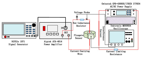
Figure 17.
Anti-interference performance test platform.
The experiment simulates the situation that the actual measurement is most susceptible to the interference of the geomagnetic field and the 50 Hz magnetic field. A current-carrying line of 2A DC and 50 Hz current is placed at a distance of 1 cm from the sensor. In the case of no external magnetic field and DC and AC interference current, the output of the sensor with and without a shielding shell is compared. The measurement current is 50 mA, and the test results are shown in Table 2.
Table 2.
Comparison of Shielding Effect under Different Interference.
It can be seen from the table that, in the case of external DC interference magnetic field, increasing the shielding shell can reduce 97.3% of the external magnetic field interference; for the power frequency interference magnetic field, increasing the shielding enclosure can reduce 95.7% of the interference. It can be seen that the designed magnetic shielding enclosure can effectively shield the interference of static magnetic field and power frequency magnetic field.
5. Conclusions
- (1)
- This paper introduces the design of a small current sensor based on the fluxgate principle, including the selection of fluxgate chip, magnetic ring structure simulation analysis, filter circuit design, and anti-interference shielding shell simulation analysis.
- (2)
- The finite element simulation of the shape of the magnetic ring was carried out. According to the simulation results, the inner diameter of the magnetic ring is 10 mm, the outer diameter is 23 mm, and the height is 8 cm. The fluxgate chip is installed at the 1/2 height of the magnetic ring. The finite element analysis of the shielding shell was also performed, and the shielding shell was determined to be 18 mm in diameter and 9 mm in height.
- (3)
- The main performance parameters of the sensor were tested. The experiments show the following: the minimum measurable current of the sensor is 1 mA; the range is 1 mA–1 A; the frequency range is DC-16 kHz; the sensitivity at DC is 1.82812 V/A and the linearity is 99.98%; and the sensitivity at 50 Hz is 1.795 V/A and the linearity is 99.99%.
- (4)
- The anti-interference performance of the sensor was tested. The results show that the influence of 97.3% of the DC interference magnetic field and 95.7% of the power frequency interference magnetic field can be reduced by increasing the shielding shell.
Author Contributions
Conceptualization, X.T.; methodology, W.L. and X.X.; validation, G.Q. and G.A.; investigation, X.T. and W.Z.; resources, R.W. and Y.K.; data curation, R.W., Y.K. and X.T.; writing—original draft preparation, X.T., W.Z. and W.L.; writing—review and editing, Y.K. and R.W.; supervision, G.Q. and G.A.; project administration, R.W. and Y.K. All authors have read and agreed to the published version of the manuscript.
Funding
This research was supported by the funding of Yunnan Academy of Science and Technology “Research and development of new smart sensor technology to promote green energy development” (202104BN050011).
Data Availability Statement
The data used to support the findings of this study are included within the article.
Acknowledgments
Not applicable.
Conflicts of Interest
The authors declare no conflict of interest.
References
- Chen, X.F.; Liu, C.W.; Wang, C. Research on Anti-interference Technology of Complex Electromagnetic Environment of TMR Current Sensor. Instrum. Tech. Sens. 2020, 1, 13–16. [Google Scholar]
- Zhou, L.Y. Study on Current Sensing Technology Based on Tunnel Magnetoresistance Effect; Chongqing University: Chongqing, China, 2019. [Google Scholar]
- Wang, L.; Zhang, W.; Tan, X.; Chen, W.; Liang, S.; Suo, C. Research and Experiments on an External Miniaturized VFTO Measurement System. Sensors 2020, 20, 244. [Google Scholar] [CrossRef] [PubMed]
- Wang, Y.; Zhou, G.; Zeng, C.; Zhang, W.; Ren, Y.; Ke, Y.; Chu, H.; Suo, C. Research on On-Line Detection Method of Transformer Winding Deformation Based on VFTO. Sensors 2021, 21, 7386. [Google Scholar] [CrossRef] [PubMed]
- Zhang, J.; Wen, Y.; Li, P. Nonintrusive current sensor for the two-wire power cords. IEEE Trans. Magn. 2015, 51, 1–4. [Google Scholar] [CrossRef] [PubMed]
- Zhang, W.; Li, P.; Zhou, N.; Suo, C.; Chen, W.; Wang, Y.; Zhao, J.; Li, Y. Method for Localization Aerial Target in AC Electric Field Based on Sensor Circular Array. Sensors 2020, 20, 1585. [Google Scholar] [CrossRef] [PubMed]
- Liu, Q. The Design of Digital Flux-Gate Sensor Based on CORTEX-M3; Harbin Engineering University: Harbin China, 2014. [Google Scholar]
- Wang, Y.; Li, K.; Ren, B.F. Study of Fluxgate Current Detecting Method for AC-DC Earth Leakage Current Based on ap FFT. Trans. China Electrotech. Soc. 2015, 30, 254–260. [Google Scholar]
- Su, C.; Xu, Y.D.; Wang, E.G.; Qiao, K.P.; Xu, H.J. Detection Method of Leakage Current of Surge Protective Device. Electr. Energy Manag. Technol. 2011, 61, 49–52. [Google Scholar]
- Li, K.; Niu, F.; Wu, Y. Nonlinear Current Detection Based on Magnetic Modulation Technology. IEEE Trans. Magn. 2015, 51, 1–4. [Google Scholar] [CrossRef]
- Yamagata, Y.; Oshi, T.; Katsukawa, H.; Kato, S.; Sakurai, Y. Development of optical current transformers andapplication to fault location systems for substation. IEEE Trans. Power Deliv. 1993, 8, 866–873. [Google Scholar] [CrossRef]
- Xu, S.Y.; Peng, Q.; Xing, F.F.; Xue, H.Y.; Sun, J.W.; Ma, L.; Li, M. A Low-Cost Current Sensor Based on Semi-Cylindrical Magnetostrictive Composite. Electronics 2020, 9, 1833. [Google Scholar] [CrossRef]
- Yang, X.G.; Guo, W.; Li, C.C.; Zhu, B.; Chen, T.G.; Ge, W.Q. Design optimization of a fluxgate current sensor with low interference. IEEE Trans. Appl. Supercond. 2016, 26, 1–5. [Google Scholar] [CrossRef]
- Yu, H.; Chang, W.Z.; Du, F. Research on Anti-Interference Principle of Current Sensor Based on Circular Array of TMR. Electr. Power Inf. Commun. Technol. 2020, 18, 7–14. [Google Scholar]
- Ripka, P.; Chirtsov, A. Influence of external current on yokeless electric current transducers. IEEE Trans. Magn. 2017, 53, 1–4. [Google Scholar] [CrossRef]
- Mlejnek, P.; Vopalensky, M.; Ripka, P. AMR current measurement device. Sens. Actuators Phys. 2008, 141, 649–653. [Google Scholar] [CrossRef]
- Yang, X.G.; Guo, W.; Li, C.C.; Zhu, B. A Fluxgate Current Sensor With a U-Shaped Magnetic Gathering Shell. IEEE Trans. Magn. 2015, 51, 1–4. [Google Scholar]
- Zhang, X.F.; Lu, Y.L. Fluxgate Technology; National Defense Industry Press: Beijing, China, 1995; pp. 1–3. [Google Scholar]
- Wang, J.; Yang, G.R. Design of the Direct Sensing Type Hall Current Sensors with 5V Power. Instrum. Technol. 2016, 12, 42–45. [Google Scholar]
- Hu, J.; Wang, B.; Sheng, F.X.; Zhao, G.; Zhao, S.; He, J.L. Design and Noise Analysis of Weak Current Sensor with Broadband Based on Tunneling Magnetoresistance Effect. High Volt. Eng. 2020, 46, 2545–2553. [Google Scholar]
- Gao, Y.G. Shielding and Grounding; Beijing University of Posts and Telecommunications Press: Beijing, China, 2004; pp. 16–17. [Google Scholar]
- Zhou, J.J.; Lin, C.S.; Hu, Y.Q. Thickness Design of Ferromagnetic Shield for Magnetic Detection. Acta Armamentarii 2012, 33, 1498–1503. [Google Scholar]


Publisher’s Note: MDPI stays neutral with regard to jurisdictional claims in published maps and institutional affiliations. |
© 2022 by the authors. Licensee MDPI, Basel, Switzerland. This article is an open access article distributed under the terms and conditions of the Creative Commons Attribution (CC BY) license (https://creativecommons.org/licenses/by/4.0/).