Article

Aerodynamic Analysis of a Low-Speed Tandem-Channel Wing for eVTOL Aircraft Considering Propeller–Wing Interaction

1
Unmanned System Research Institute, Northwestern Polytechnical University, Xi’an 710072, China
2
School of Aeronautics, Northwestern Polytechnical University, Xi’an 710072, China
3
UAV Laboratory, Institute of Engineering Thermophysics (IET), Chinese Academy of Sciences, Beijing 100190, China
*
Author to whom correspondence should be addressed.
Energies 2022, 15(22), 8616; https://doi.org/10.3390/en15228616
Submission received: 18 October 2022 / Revised: 3 November 2022 / Accepted: 8 November 2022 / Published: 17 November 2022

Abstract

:
Fixed-wing aircraft with vertical takeoff and landing capabilities need a lower speed and a higher lift during transition. To meet these needs, a tandem-channel wing layout has been developed, including a FLR (front wing lower than rear wing) configuration and a FUR (front wing upper than rear wing) configuration, which differ in height differences between the front and rear wings. Numerical simulations have been performed to investigate the aerodynamic characteristics of the two configurations. The results show that a significant increase in lift coefficient occurs when the propeller rotational speed and the angle of attack increase. The lift at a small angle of attack increases by more than 50% at a high propeller rotational speed, and the stall angle of attack increases by more than 10 degrees. For the FLR configuration, the downwash effect of the front wing impacts the rear wing, decreasing the local angle of attack and delaying airflow separation on the top surface. For the FUR configuration, the up surface of the rear wing is induced by the wake flow of the front wing propeller at a high propeller rotational speed, which increases the lift and the stall angle of attack but makes the aircraft have static instability.

1. Introduction

Uber [1], NASA [2], Airbus [3], Embraer [4], MITRE [5], EHang [6] and other organizations have introduced the concept of UAM (Urban Air Mobility) in recent years. With technology developments in electric propulsion, autonomous driving, 5G connectivity, and other fields [7], urban aircraft have achieved fundamental technological viability, expanding the options for future cities.
Powered by electric motors, an eVTOL (Electric Vertical Take-Off and Landing) aircraft is capable of vertical takeoff and landing to adapt to complex urban environments. Multirotor aircraft can adapt effectively to vertical takeoff and landing requirements, but their cruise efficiency is low. They can only fly at a low speed, and cruise time and range are short. Fixed-wing aircraft with vertical takeoff and landing capabilities are believed to offer considerable potential for enhancing aerodynamic efficiency, carrying capacity, environmental protection, and durability. During the transition from takeoff to cruise, the aircraft’s lift source progressively moves from the rotors to the wing, followed by complicated unstable aerodynamics. To finish the conversion process quickly, the aircraft should have a large stall angle of attack and a high max lift coefficient.
The channel wing, invented by W. R Custer [8] in the 1920s, has excellent lift characteristics and is an ideal choice for urban aircraft. The channel wing consists of a straight wing segment and a semiring wing segment. The semiring wing segment is equipped with a propeller in the front. The propeller can not only provide the required thrust of the aircraft, but also accelerate the air flow on the upper surface of the rear of the semiring wing through the induction of its wake to expand the low-pressure area on the upper surface of the semiring wing, so as to significantly improve the lift of the wing. In 1953, NACA [9] conducted a series of wind tunnels on channel-wing aircraft in a full-size wind tunnel at Langley to study the lift and control characteristics of channel wing aircraft. In 1973, Edgington [10] used the lift line method to study the lift and drag characteristics of a channel wing with different airfoil profiles and aspect ratios, and the results proved that the lift coefficient was higher than the conventional oval wing. In 2001, Nangia and Palmer [11] studied the difference between the channel wing and the straight wing at a low speed, and the results showed that the channel wing had an obvious lift increment, and the introduction of a sweep angle would improve the lift and pitch moment of channel wing aircraft to a certain extent. It is found that when the phase angle of the hemicyclic wing changes from 0° to 135°, the lift of the wing increases obviously, but when the phase angle changes from 135° to 180°, the lift increase is relatively limited. From 2002 to 2005, Englar and Campbell [12,13] combined trailing edge flow control with a channel wing and proposed a combined lift enhancement configuration with the help of the Coandă effect, which greatly improved the stall angle of attack and available lift coefficient of the aircraft. From 2012 to 2014, Muller [14,15,16] studied the combination of flaps and on-wing propellers in the takeoff stage, and proved that the channel wing would significantly enhance the wing lift, but the uneven inflow would cause periodic changes in the load of the propeller disc, weakening the net thrust. At the same time, increasing the depth of the semiring wing is helpful to improve the lift–drag ratio, but it will reduce the propeller efficiency to a certain extent. When the propeller is arranged near the leading edge, the drag can be effectively reduced. In 2015, Keane et al. [17] proposed a small unmanned aerial vehicle based on a channel wing, and conducted a series of numerical simulation and wind tunnel and flight tests. Tests show that the channel wing aircraft have a lower flight speed. However, the efficiency of the control surface and the stabilizer surface of the tail will be sharply reduced, which will seriously degrade the stability of the aircraft. Shafie [18] et al. conducted tests on channel wings with different chord lengths, and the test results showed that increasing the chord length of channel wings could effectively enhance the lift capacity of wings, but the static thrust of propellers would be slightly reduced.
Considering other aerodynamic simulation including rotational parts, a lot of work has been performed. Cravero et al. [19] provide a detailed analysis of the flow structures generated by the interaction between a multielement inverted wing and the wheel of an open-wheel race car. Fernandez-Gamiz et al. [20] study the aerodynamics of Gurney flaps and microtabs used passive flow control devices on wind turbines. Basso et al. [21] indicate that the Gurney flap enhances the ground effect, by redistributing the flow that interacts differently with the other components, i.e., the wheel zone.
Existing studies substitute the traditional aircraft’s main wing with a channel wing to examine its aerodynamic properties. The tandem-wing layout aircraft has front and rear wings, and replacing wings with channel wings may maximize the channel wing’s high lift characteristics. Consequently, this study proposes a tandem-channel wing layout aircraft, which can be divided into FLR (front wing lower than rear wing) and FUR (front wing upper than rear wing) configurations based on the height difference between the front and rear wings. The aerodynamic characteristics of the above configurations under different angles of attack and propeller rotational speeds are analyzed using CFD. Section 2 discusses the numerical methodology. In Section 3, two configurations of the tandem-channel wing layout are explained in detail based on the study of the propeller position. Then, the aerodynamic characteristics of the two configurations under different attack angles and propeller rotational speeds are numerically simulated, and the aerodynamic forces and moments of the two configurations without propellers are calculated. In Section 4, the characteristics of the tandem-wing layout are summarized, which provides a basis for the subsequent detailed design.

2. Numerical Simulation Approaches

2.1. Governing Equations

In this paper, the finite volume method is used to solve the Reynolds Average Navier–Stokes (RANS) equation. The equation can be written in the inertial coordinate system:
t V W d V + S ( F c F V ) n d S = 0
n = [ n x n y n z ] T
In the formula above, S is the area of the contiguous volume, and V is the volume of the contiguous volume. The vector n represents the surface normal vector of the control element. The vector Fc represents convective transport quantities, while the vector FV represents viscous fluxes. The vector W is a conserved variable. The vector Fc, FV and W can be written as:
W = [ ρ ρ u ρ v ρ w ρ E ] F = [ ρ V r ρ u V r + n x p ρ v V r + n y p ρ w V r + n z p ρ H V r + V t p ] F v = [ 0 n x τ x x + n y τ x y + n z τ x z n x τ y x + n y τ y y + n z τ y z n x τ z x + n y τ z y + n z τ z z n x Φ x + n y Φ y + n z Φ z ]
where p and ρ are the pressure and density of the gas, respectively. E and H represent the total energy and total enthalpy of the gas unit mass. The velocity components in the three directions are indicated by the letters u, v, and w. Vr is the relative velocity between body and flow field and Vt is the relative velocity of mesh unit. τij is connected to the viscous fluxes of these components, whereas Φi is related to heat conduction. When solving the RANS equation, the turbulence model is required to describe Reynolds stress in order to close this system of equations. In this research, the k-ω Shear Stress Transport (SST) model [22] is used for CFD numerical simulation. The high-resolution normalized variable (NVD) approach is used to compute the solver’s spatial difference.

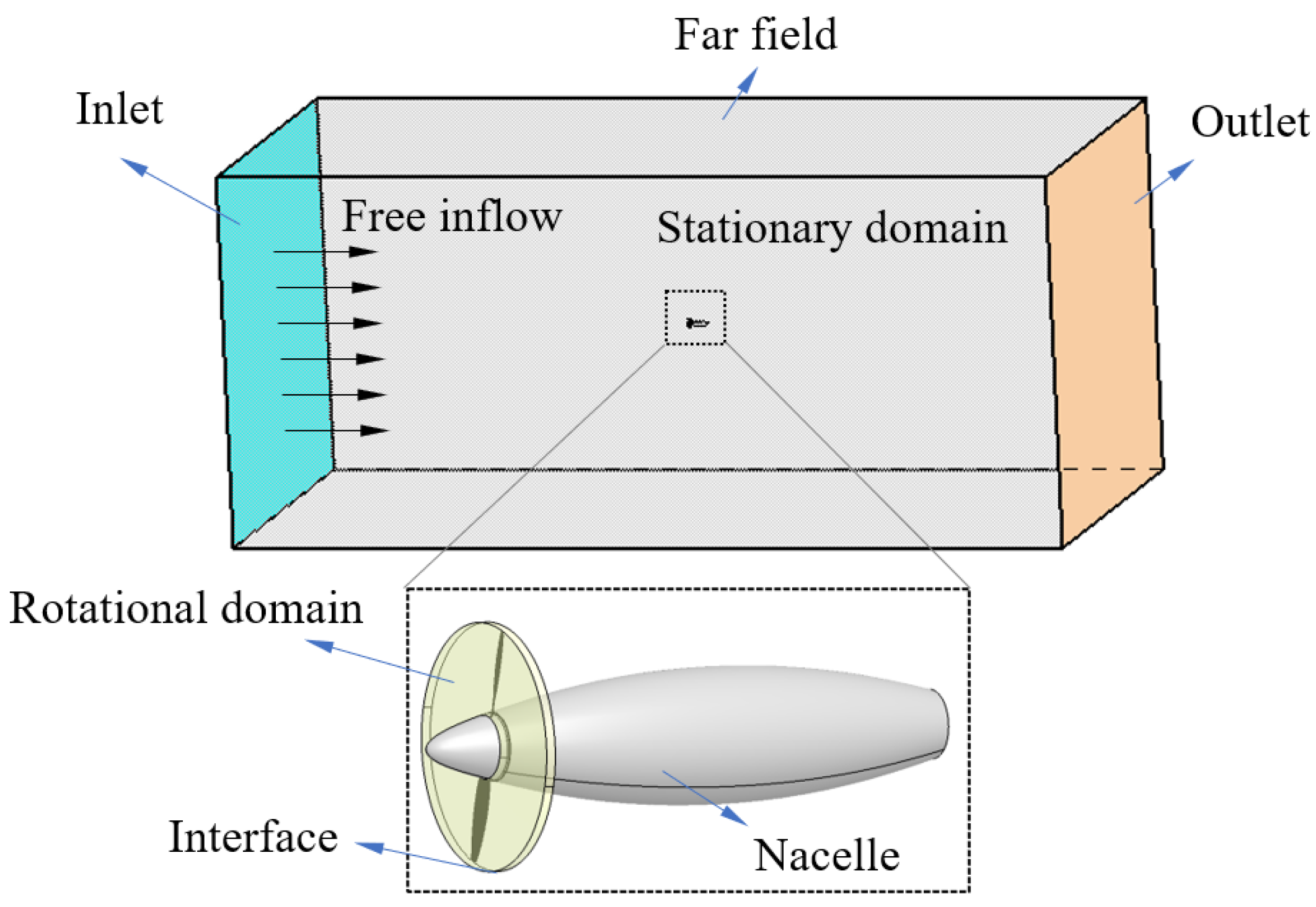
2.2. The Multiple Reference Frame Method and Boundary Condition

The quasi-steady numerical simulation approach based on the RANS method and the multiple reference frame (MRF) method [23] is used to compute propeller-related issues. The main idea of the MRF method is to establish a closed cylindrical region around the propeller, which is called the rotational domain. The rest of the region is called the stationary domain. The grid in the rotational domain is generated separately from the grid in the stationary domain. There are interfaces between the rotational domain and the stationary domain for flux transfer. The schematic diagram is shown in Figure 1.
In the rotational domain, the equation is solved in a rotating reference frame, while in the stational domain, the equation is solved in a fixed reference frame. Using a frozen rotor approach, the velocity entering the rotational domain is transferred to a rotating reference frame:
v MRF = v ω × r
where vMRF is the velocity in the rotating reference frame, v is the velocity in the stationary reference frame, ω is the rotational vector and r is the position vector in the rotational domain. The MRF method can transform the complex unsteady motion into a quasi-steady flow problem, thereby reducing the computational difficulty and improving the computational efficiency.
In viscous flow, the velocity of the fluid is the actual velocity of the body on the body surface. The wall is set as an adiabatic wall, and the wall pressure is obtained by linear interpolation:
p w a l l = p 1 ( p 2 p 1 ) 2
where p1 and p2 is the pressure of the first and the second layer grid. The pressure far-field boundary is a type of non-reflective boundary condition that is defined by using Riemann invariants under the local one-dimensional assumption. There are two Riemann invariants in subsonic flow:
R = V n 2 c γ 1 , R i = V n i 2 c i γ 1
where Vn is the normal velocity, c is the local speed of sound, and the subscript i represents the computational domain. By adding and subtracting the two equations above, it can be obtained:
V n = R + R i 2   c = γ 1 4 ( R i R )
where Vn and c are the normal and sound velocities on the boundary, respectively. The tangential velocity and entropy can be obtained by extrapolating the internal flow field on the outflow boundary. On the boundary of inflow, they are taken from the value of free inflow.

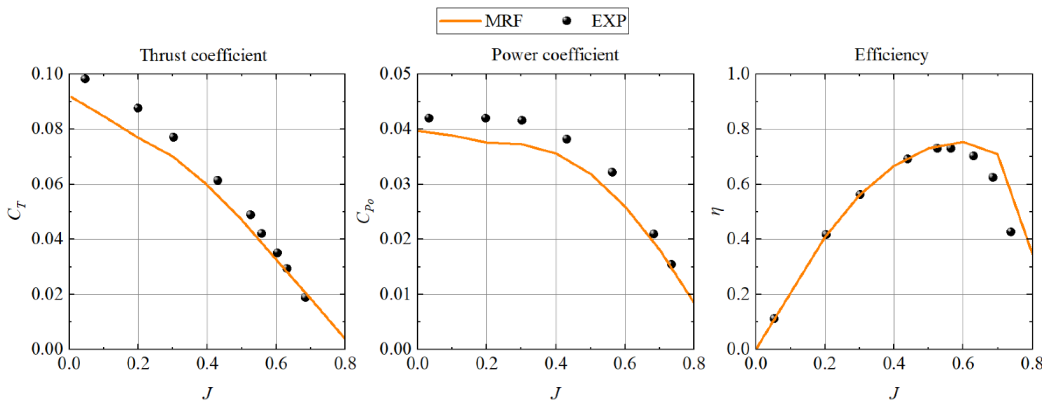
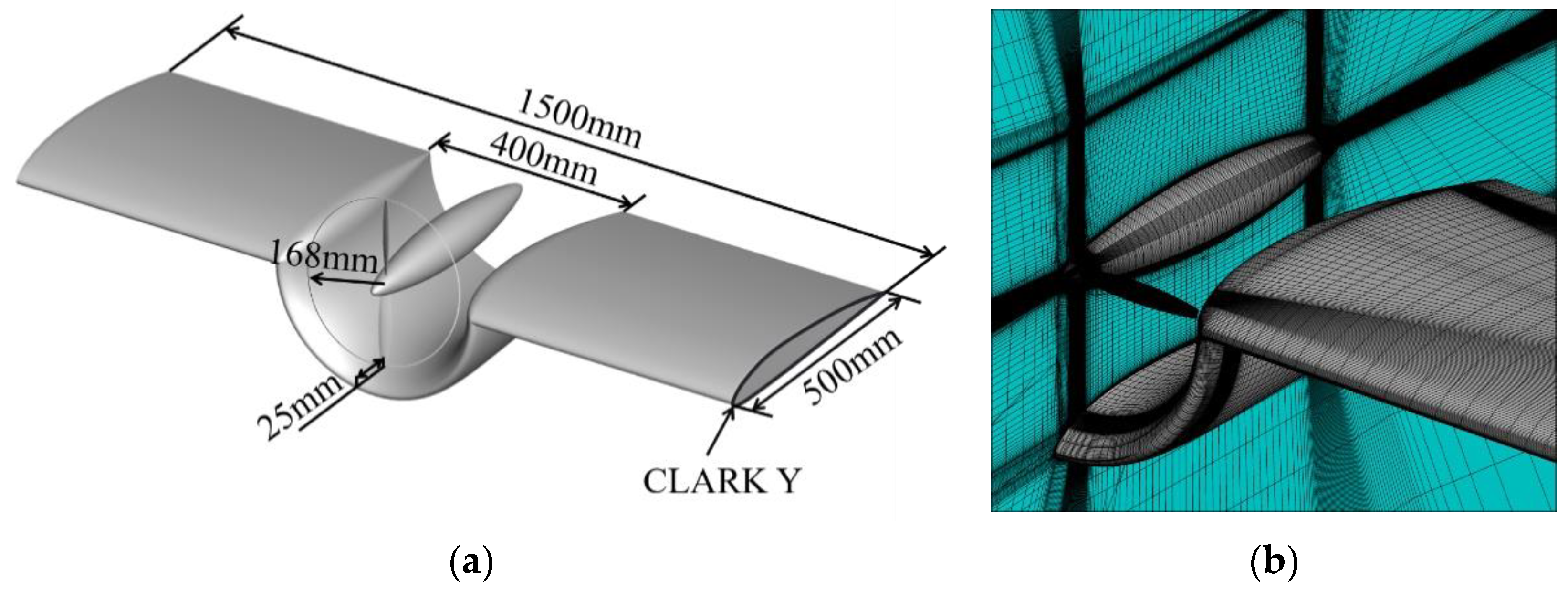
2.3. Methodology Validation

As shown in Figure 2, a standard propeller model is selected to verify the reliability of the solver. A series of wind tunnel tests have been carried out on this model at Wichita State University, Kansas, USA [24], with abundant experimental data, which can be used for verification in this paper.
Three meshes are generated to obtain grid convergence and determine the proper near-wall mesh point distribution. Table 1 shows the details of the meshes used for the evaluation. The most important quality criterion is the distribution of near-wall grid points, especially for y1+ = Δy1uτ/v where Δy1 represents the distance away from the wall of the nearest grid point and u τ = τ w / ρ stands for the shear stress velocity with τw the wall shear stress and v the kinematic viscosity. The advance ratio, J, is set to 0.73 as the propeller works at n = 6000 rpm. The advance ratio, J, is defined as:
J = V n D
where V is the velocity of the free inflow, n is the propeller rotational speed, and D is the diameter of the propeller. The pressure distribution on the upper surface of the nacelle at the vertical symmetry plane was extracted, as shown in Figure 3. The y1+ ≈ 0.4 will be the criterion in the following grid generating process.
The simulation results of the thrust coefficient, CT, the power coefficient, CPo, and efficiency, η, in different advance ratios, J, of the propeller working at n = 6000 rpm is obtained using the MRF method. The above parameters are defined as:
{ C T = T ρ n 2 D 4 C P o = P ρ n 3 D 5 η = J C T C P J = V n D
where T is the tension of the propeller, P is the power of the propeller, and ρ is the density of the free inflow. Figure 4 shows the static domain grids, rotational domain grids, and combined grids. The total number of grid points in the computational domain is 4.3 million, and the first grid distance is kept in a value of y1+ ≤ 1.
Based on Figure 5, the maximum error between the numerical simulation results of the propeller tension coefficient and the wind tunnel test data is 9.1%, the maximum error of the power coefficient is 10.1%, and the maximum error for efficiency is 5.6% when the advance ratio, J, of the propeller is less than 0.7. It can be considered that the MRF method can effectively simulate the propeller aerodynamic characteristics. The simulation accuracy of this method meets the research requirements for this paper.

3. Results and Discussion

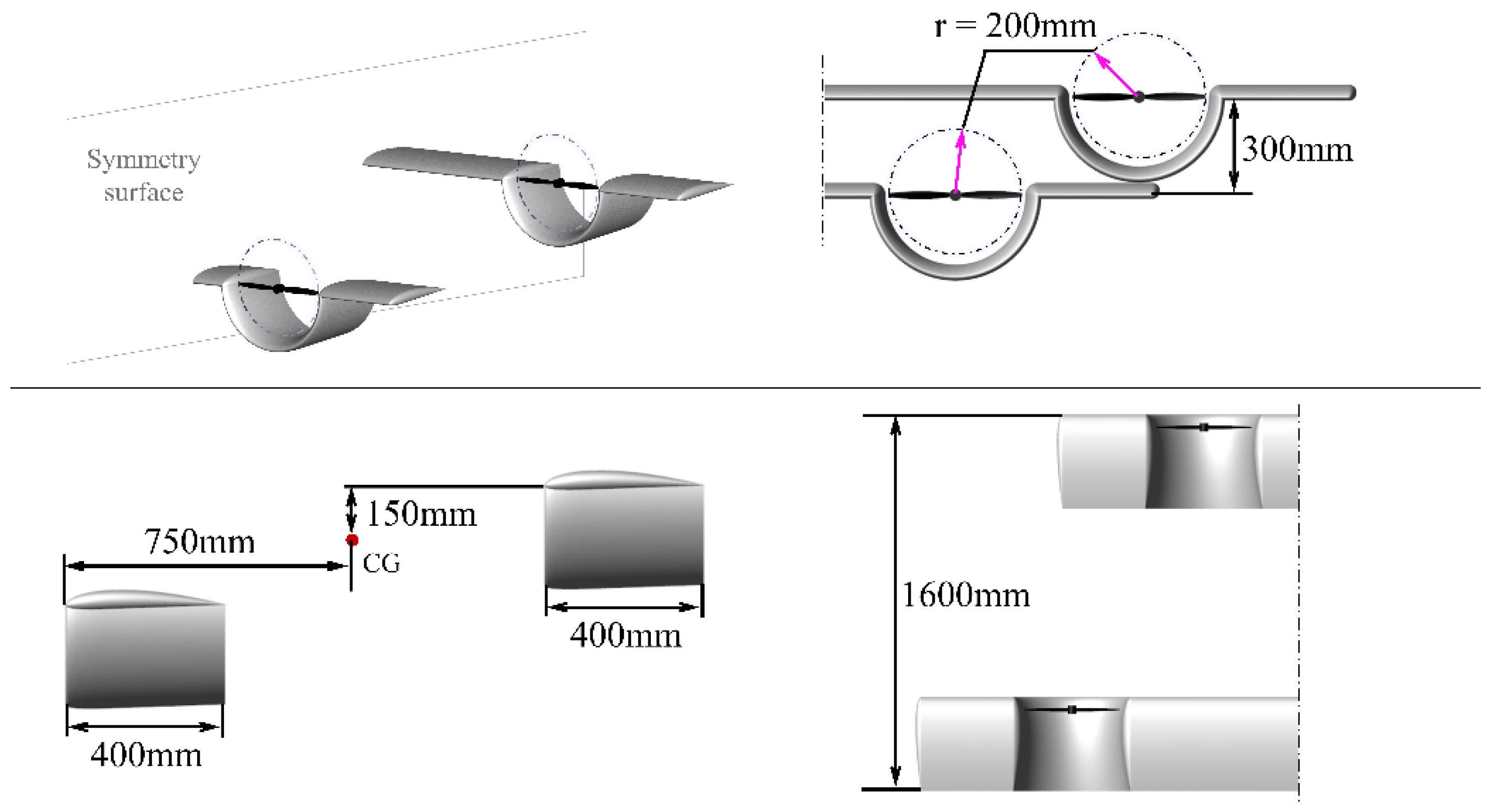
3.1. Tandem-Channel Wing Layout

A channel wing consists of a straight wing segment and a semiring wing section equipped with a propulsion system near the leading edge, as shown in Figure 6a. The advance ratio, J, is set as 0.2, the propeller speed is set as 6000 rpm, and the angle of attack is set as 0°. Figure 6b shows the grid, which satisfies y1+ ≤ 1 and is approximately 11.1 million grid points.
The upper surface of the semiring wing is in the propeller’s wake. At a high propeller rotational speed, the low-pressure zone of the top surface extends from the leading edge to the trailing edge, considerably enhancing the lift force. As shown in Figure 7, the propeller wake is concurrently driven downward by the Coandă effect at the trailing edge, resulting in a downwash effect on the rear object surface. At a distance of 4 fold the chord length of the ring wing from the propeller, the downwash velocity is 45% of the incoming flow velocity, while it remains 30% of the incoming flow velocity at a distance of 5 fold the chord length of the semiring wing.
The channel wing with the rear propeller is shown in Figure 8a. Figure 8b shows the grid, which satisfies y1+ ≤ 1 and is approximately 11.2 million grid points. The calculation conditions are the same as the simulation above. In contrast to the conventional channel wing, the downwash effect of the channel wing with the propeller at the rear of the ring wing is much less. At one chord length from the propeller, the data in Figure 9 indicate that the washing speed is near to zero.
The tandem-wing layout consists of two wings at the front and back of the aircraft. The Vahana vehicle developed by A3 by Airbus LLC [25] has used the tandem-wing layout, as shown in Figure 10. For an aircraft with the tandem-wing layout, the wake of the front wing influences the aerodynamics of the rear wing. The low front wing may minimize the downwash influence on the airflow near the rear wing by keeping the downwash wake away from the rear wing. For the tandem-channel wing layout, FLR (front wing lower than rear wing) configuration is considered to reduce interference to the rear wing, as shown in Figure 11. The wingspan of the front and rear ring wings is 500 mm, the half-span of the front wing is 1000 mm, and the half-span of the rear wing is 1600 mm. The propeller has a radius of 200 mm, and the difference in height between the straight wing segments of the front and rear wings is 300 mm. The center of gravity is taken on the symmetric plane, 750 mm from the leading edge of the front wing, 150 mm higher than the straight wing section of the front wing.
Considering the channel wing with rear propeller, the downwash effect is relatively weak and still has considerable horizontal velocity at the wake, while the straight wing segment of the rear wing is in the wake region of the front wing propeller. Therefore, the FUR (front wing upper than rear wing) configuration is considered to accelerate the air flow on the upper surface of the straight wing segment in the rear wing by the high-speed slip flow of the front wing propeller, so as to achieve the induced lift enhancement effect, as shown in Figure 12. The dimensions of each component of this configuration are identical to those of the FLR configuration, except that the straight wing segment of the front wing is 300 mm higher than that of the rear wing and the center of gravity is the same in the horizontal direction but 150 mm lower in the longitudinal direction than that of the straight wing segment of the front wing. Table 2 shows the geometric parameters of the two configurations.
The geometric parameters of the two configurations are as follows:

3.2. Aerodynamic Characteristics of the FLR Configuration

The mesh for simulation is a hybrid unstructured hexahedral mesh which converted from the structured mesh with grid size of approximately 13.6million, which is composed of the stational domain meshes (approximately 2.6 million) and the rotational domain meshes (approximately 11 million), as shown in Figure 13. The Δy1 of the mesh is 2.4 × 10⁻⁶ and y1+ ≤ 1. The velocity of free inflow is 20 m/s, and the angle of attack is set as 0°. The lift, drag and moment coefficients of this configuration at different propeller rotational speeds are calculated, and the moment reference point is the center of gravity position mentioned in Section 3.1. The result is shown in Figure 14. With the increase in the propeller rotational speed, the lift coefficient of the aircraft gradually increases, and the semiring wing of the front and rear channel wings is the main lift contributor. The lift of the inner and outer wing segments of the front wing and the outer wing segments of the rear wing increase slightly at a high propeller rotational speed, while the lift of the inner wing segments of the rear wing decrease. The lift of the front semiring wing is higher than that of the rear semiring wing, and this disparity increases as the propeller rotational speed rises. Similar to the change in lift coefficient, the change in drag and moment coefficients are focused in the ring wing. The drag coefficient decreases with the increase in the propeller rotational speed. Additionally, since the lift increment of the front ring wing is greater, the nose-up pitching moment of the aircraft steadily rises with the propeller rotational speed.
The lift distributions of the front and rear wings in the span direction under the conditions of n = 4000 rpm and n = 8000 rpm were extracted and compared with the unpowered configuration, so as to reveal the main factors leading to component force variation. The unpowered configuration means that the same configuration does not contain the propeller. As shown in Figure 15, when the propeller rotational speed is 4000 rpm, the wing lift distribution over the span is comparable to that of an unpowered version, and there is no substantial induced lift effect from the propeller. The lift of the front and rear semiring wings increases dramatically as the propeller rotational speed increases, and the lift of the semiring wings was mostly centered on the side closest the wing root. The lift peak of the front semiring wing is higher than that of the rear semiring wing, and the lift of the straight wing near the ring wing increases.
Figure 16 shows the surface pressure distribution cloud diagram for the whole aircraft for two different propeller rotational speeds. The increase in the propeller rotational speed further accelerates the air flow on the semiring wing’s upper surface, and the low-pressure region expands, resulting in an increase in lift. The propeller is in the horizontal phase and turns clockwise from nose to tail, the lift peak occurs on the side of the semiring near the root. The straight wing at the two sides of the ring wing is driven by the axial and annular velocity of the propeller, and the air flow on its upper surface is accelerated, resulting in a modest increase in lift force.
The impact of the front wing tip vortex on the rear wing is shown in Figure 17. The front wing tip overlaps the rear semiring wing in the span direction, while the wing tip vortex deviates the airflow in front of the rear ring wing propeller from the X-axis and introduces velocity components in the other directions. In addition, the velocity of incoming flow decreases after passing through the front wing and does not recover at the rear wing. The adverse interference of the aforementioned factors causes the inflow boundary conditions of the rear semiring wing to differ from the free inflow of the front semiring wing, which has a negative impact on the coupling lift increase effect of the propeller and the wing, resulting in a reduction in the lift peak of the rear ring wing and the overall lift.
For this configuration, the lift and moment at different angles of attack are calculated at propeller rotational speed n = 4000 rpm and n = 8000 rpm, and compared with the unpowered configuration. The calculation results are shown in Figure 18. When n = 4000 rpm, the lift coefficient of this configuration is comparable to that of the unpowered version at a lower angle of attack, and the stall angle of attack rises from 16° to 20° under the influence of the propeller. The nose-down pitching moment of the two configurations show a trend of increasing first and decreasing, and the inflection point is around 20°. At n = 8000 rpm, the lift coefficient increases by approximately 0.1 at each angle of attack, and the stall angle of attack rises to 24°. After the stall angle of attack, the lift coefficient drops gradually. The nose-down pitching moment rises monotonically. The center of gravity specified in Section 3.1 serves as the reference point for the pitch moment coefficient curve. The static stability margin can be obtained from: Hn = −dCm/dCL. The static stability margin is 30% calculated by linear regression. At this time, the aircraft cannot meet the requirements of cruise trim. In actual aircraft design, it is necessary to design the front and rear wing mounting angles or coordinate the elevator deflection in detail to achieve cruise moment trim.
The lift coefficient of each component is shown in Figure 19 as a function of the angle of attack. When n = 4000 rpm, the propeller power-induced lift effect is not obvious, which is similar to the lift characteristics of the unpowered configuration. When n = 8000 rpm, the power-induced lift effect is significant. With the increase in the angle of attack, the lift of the front and rear semiring wings continue to increase. The rest of the components appear stall at a high angle of attack, and the lift of the inner of the rear wing decreases slowly.
The two-dimensional flow field at the symmetry plane of the front and rear ring wings at an attack angle of 24° is extracted, while the whole plane is in a stall condition, as shown in Figure 20. At the semiring wing, with the increase in the propeller rotational speed, the stall of the semiring wing is significantly inhibited, and the flow separation point gradually approaches the backward edge. Therefore, at a high propeller rotational speed, the lift coefficient still increases when the angle of attack increases.
The flow field of the rear inner wing corresponding to the section of the symmetrical plane of the front ring wing is extracted, as shown in Figure 21. With the increase in the propeller rotational speed, the downwash effect of high-speed slipstream on the front wing is gradually enhanced, and the local angle of attack of the rear wing is gradually decreased, which maintains the attached flow of the rear wing and effectively improves the available angle of attack of the inner wing segment of the rear wing.

3.3. Aerodynamic Characteristics of the FUR Configuration

The grid size for simulation is approximately 14 million, which satisfies y1+ ≤ 1, as shown in Figure 22. The velocity of free inflow is 20 m/s, and the angle of attack is set as 0°. Figure 23 shows the aerodynamic characteristics of the FUR configuration at different propeller rotational speeds. As the speed increases, the lift of the front and rear ring wings increases significantly. The inner and outer segments of the front wing and the outer segment of the rear wing increase slightly at higher rotational speeds. In this configuration, the lift increment of the front and rear wings is comparable, hence the overall aircraft moment changes slightly with the propeller rotational speed. In addition, the drag coefficient of front semiring wing stays unchanged, while the figure for rear semiring wing decreases obviously.
As shown in Figure 24, the spanwise lift distributions of the front and rear wings of this configuration at various propeller rotational speeds are taken. The lift distribution of the rear semiring wing is not significantly disturbed because the front wing of the FUR configuration is higher, in contrast to the lift loss of the rear wing caused by the interference of the front wing of the FLR configuration. The front semiring wing’s lift peak is smaller, but its lift is greater across the whole ring wing. At higher speeds, there is a noticeable lift increase in the inner wing segment of the rear wing.
As the front wing propeller is located at the rear of the ring wing, the lift effect of the front semiring wing is generated from the suction effect in front of the propeller, which is mainly concentrated near the trailing edge. Compared with the rear semiring wing, the suction peak in the front ring wing is further back and the negative pressure recovery is more delayed, which is more significant with the increase in speed, as shown in Figure 25.
Similar to the FLR configuration, the lift increase effect of the front and rear semiring wings is reflected in the higher propeller speed, and the rear inner wing also has a significant lift increase. The spatial velocity distributions at n = 4000 rpm and n = 8000 rpm were extracted, as shown in Figure 26. At high speeds, the front ring wing’s high-speed slipstream induces the up surface of the inner wing segment of the rear wing significantly. The upper surface velocity of the inner wing segment of the rear wing increases, and the low-pressure area increases, as shown in Figure 27.
For this configuration, the lift force and moment at different angles of attack are calculated at propeller rotational speed n = 4000 rpm and n = 8000 rpm, and the results are shown in Figure 28. When the propeller rotational speed is n = 4000 rpm, this configuration approximates the lift coefficient of the corresponding unpowered configuration at a lower angle of attack. At low angles of attack, the nose-down pitching moment rises with the angle of attack, and the nose-down pitching moment of the unpowered configuration is greater, with the difference growing progressively with the angle of attack. In the vicinity of a stall angle of attack, the nose-down pitching moment of both have a decreasing trend. When the propeller rotational speed is n = 8000 rpm, the lift coefficient increases by approximately 0.15 at each angle of attack, and the stall angle of attack and the maximum lift coefficient increase significantly. However, at this time, the nose-up pitching moment has a slowly rising trend with the angle of attack, that is, the aircraft has static instability at the current propeller rotational speed.
As indicated in Figure 29, the lift of each component at various propeller rotational speeds is determined. When n = 4000 rpm, the lift and variation trends of each component are similar to the unpowered configuration, and the stall angle of attack is around 18 degrees. When n = 8000 rpm, the lift of each component of the front wing and the rear ring wing increases constantly with the angle of attack, with the increase in the front ring wing being larger than that of the rear ring wing.
The pressure distribution on the upper surface and the two-dimensional flow field at the symmetry plane of the front and rear ring wings at a 24° angle of attack are extracted, as shown in Figure 30. When n = 4000 rpm, the pressure distribution on the surface of the front and rear semiring wings is quite different due to different propeller positions. The rear propeller accelerates the fluid in front of the disc, making the low-pressure area of the front semiring wing wider, while the front propeller affects the rear semiring wing through slipstream, making the low-pressure area more concentrated and the flow more complex. However, the lift characteristics and flow characteristics are similar, and there are large separation vortices at the rear of the airfoil. When n = 8000 rpm, the position of the separation vortex moves backward significantly, while the separation vortex area of the front ring wing is smaller and the attached flow area is larger, so that the upper surface has a larger low-pressure area and thus has a larger lift force.

4. Conclusions

As eVTOL (Electric Vertical Take-Off and Landing) aircraft require a low transition speed and a high lift, this paper discusses a tandem-channel wing layout for eVTOL, including FLR (front wing lower than rear wing) and FUR (front wing upper than rear wing) configurations. The aerodynamic force and moment at various angles of attack and propeller rotational speeds are analyzed numerically. The mechanism is revealed by the pressure distribution, the velocity distribution, and the flow field distribution. Compared with the corresponding unpowered configuration, the changes of aerodynamic characteristics induced by the propeller are revealed. The following are the conclusions:
1.
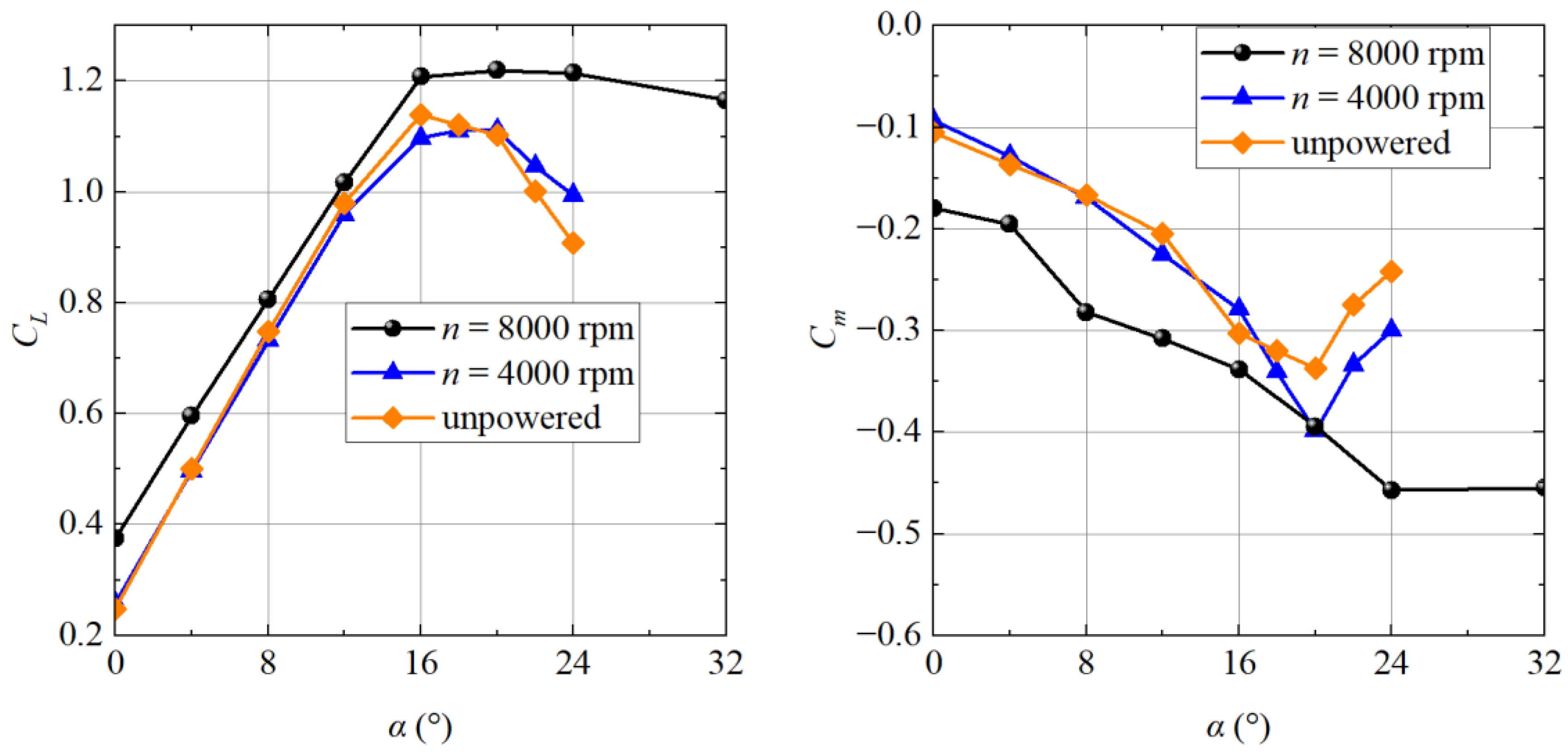
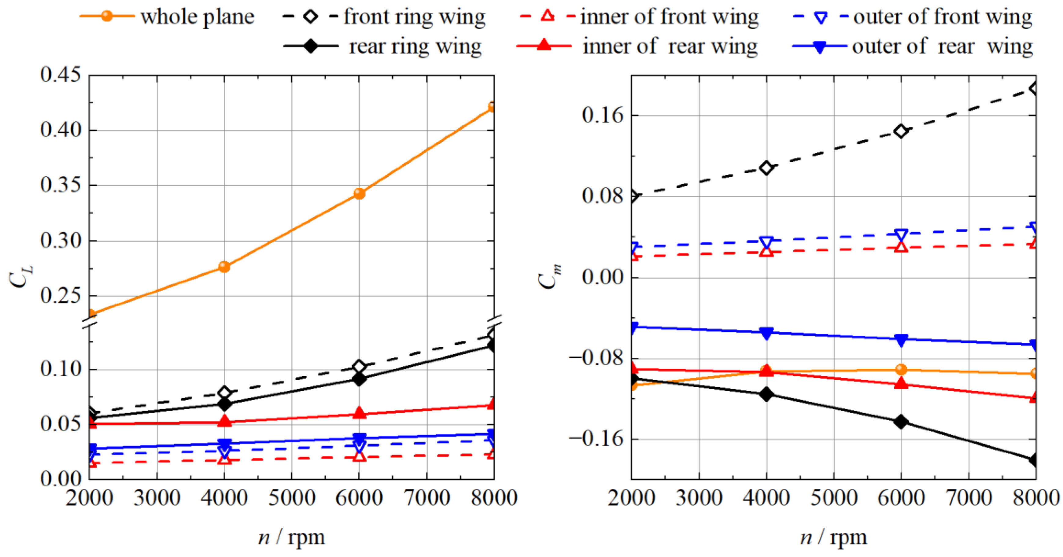
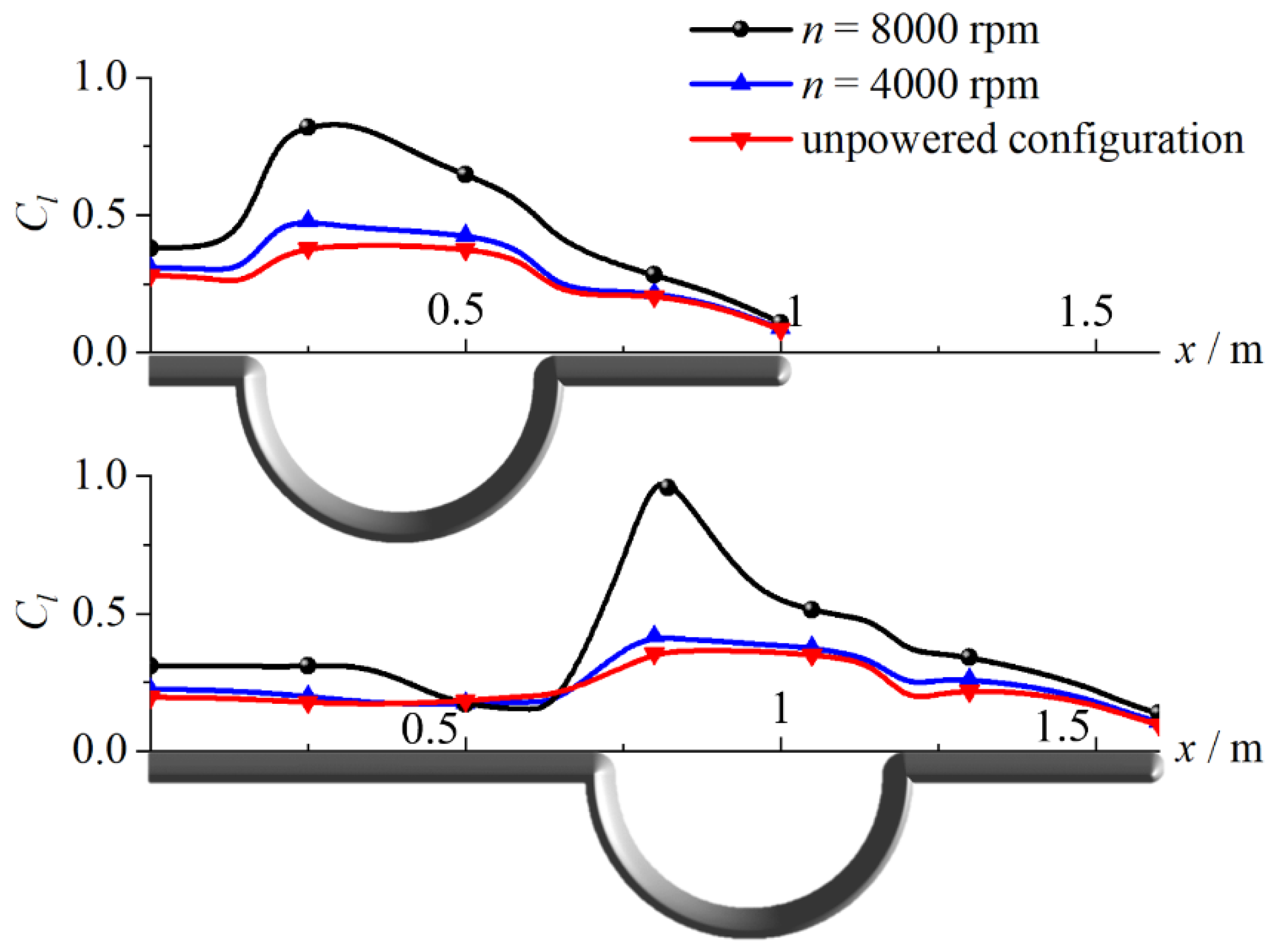
At a high propeller rotational speed, the tandem-channel wing configuration lift greatly increases. At a 0° angle of attack, the lift rises by more than 50 percent. At a stall angle of attack, the lift increases by approximately 10 percent; and at a maximum angle of attack for stalling, the lift increases by more than 10 degrees.
2.
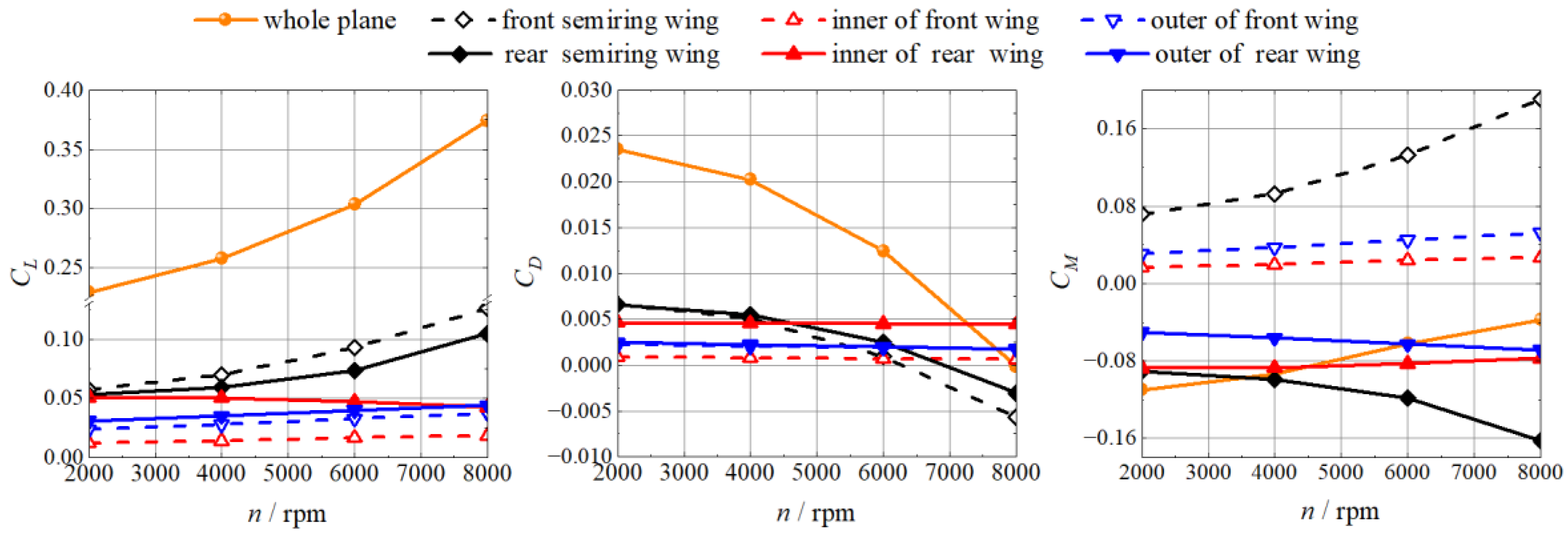
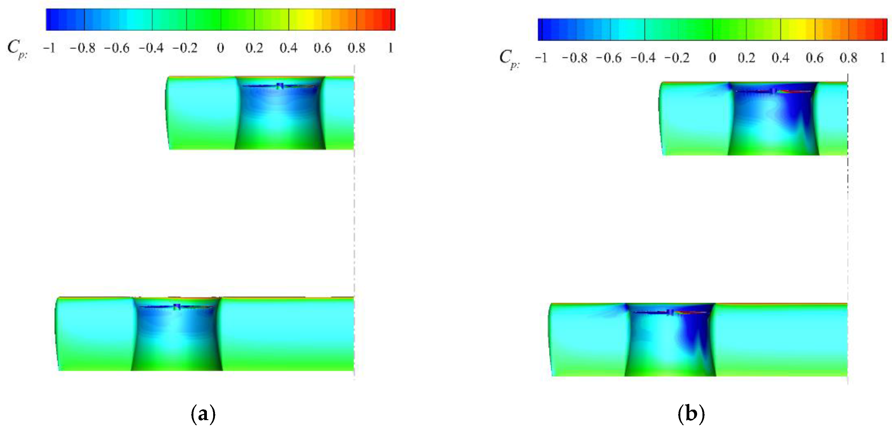
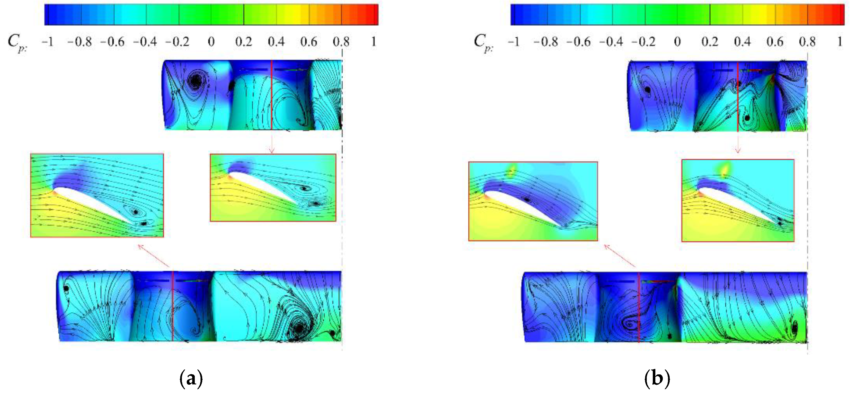
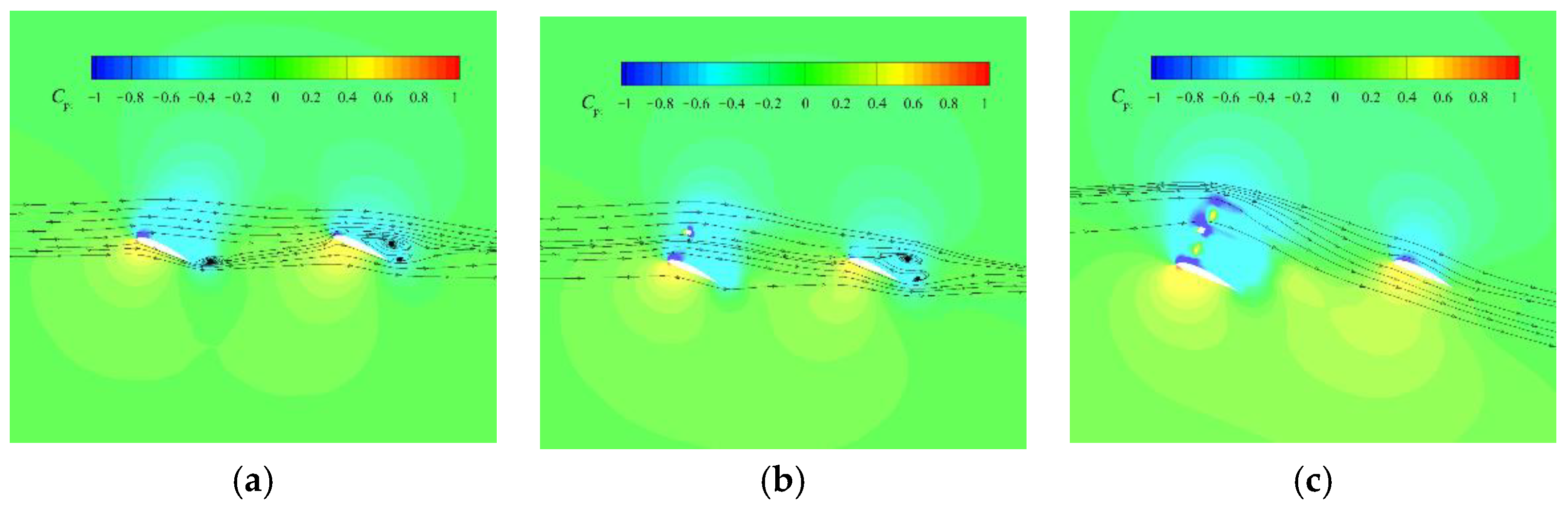
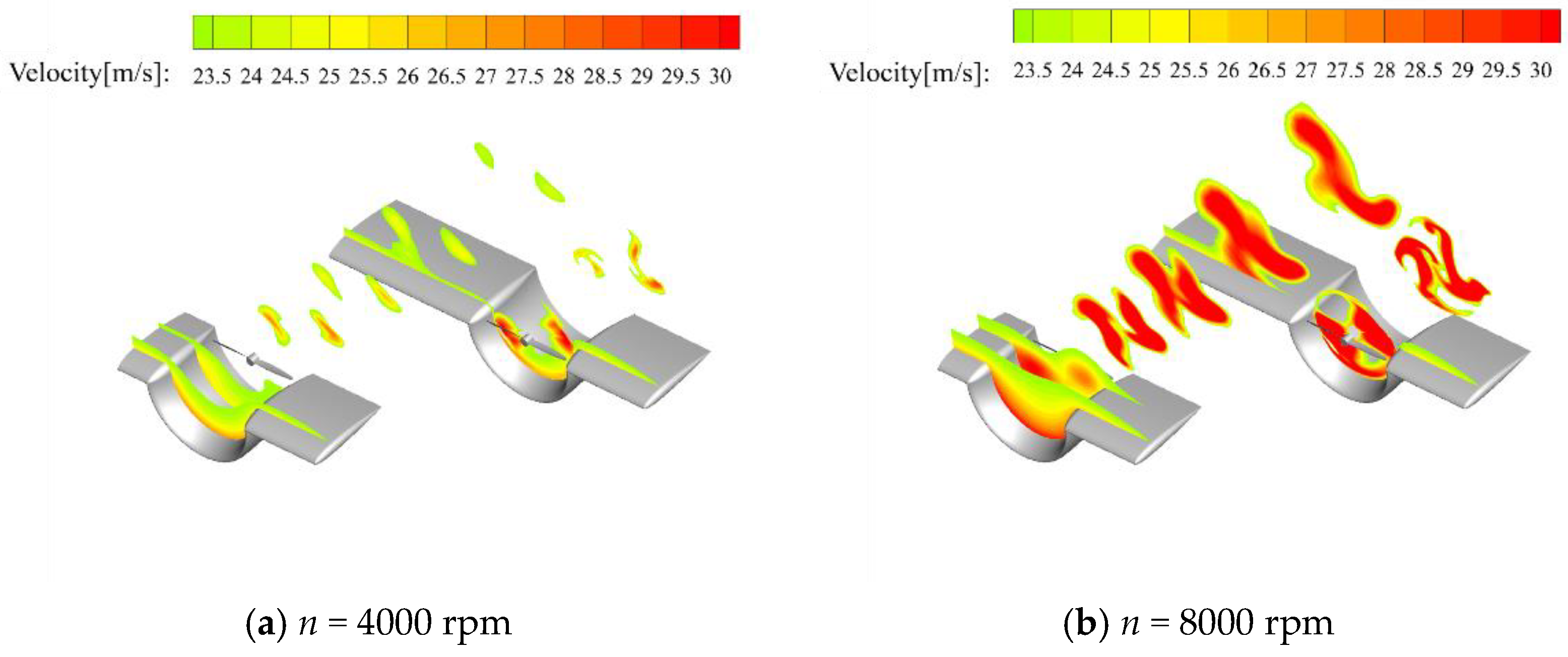
The tandem-channel wing’s increased lift is caused by the propeller’s acceleration of the air flow on the top surface of the semiring wing, which enlarges the region of low pressure on the upper surface. Simultaneously, the propeller also generates a small increase in lift on the neighboring straight wing section to the ring wing. The rear propeller is more effective than the front propeller in inducing lift rise.
3.
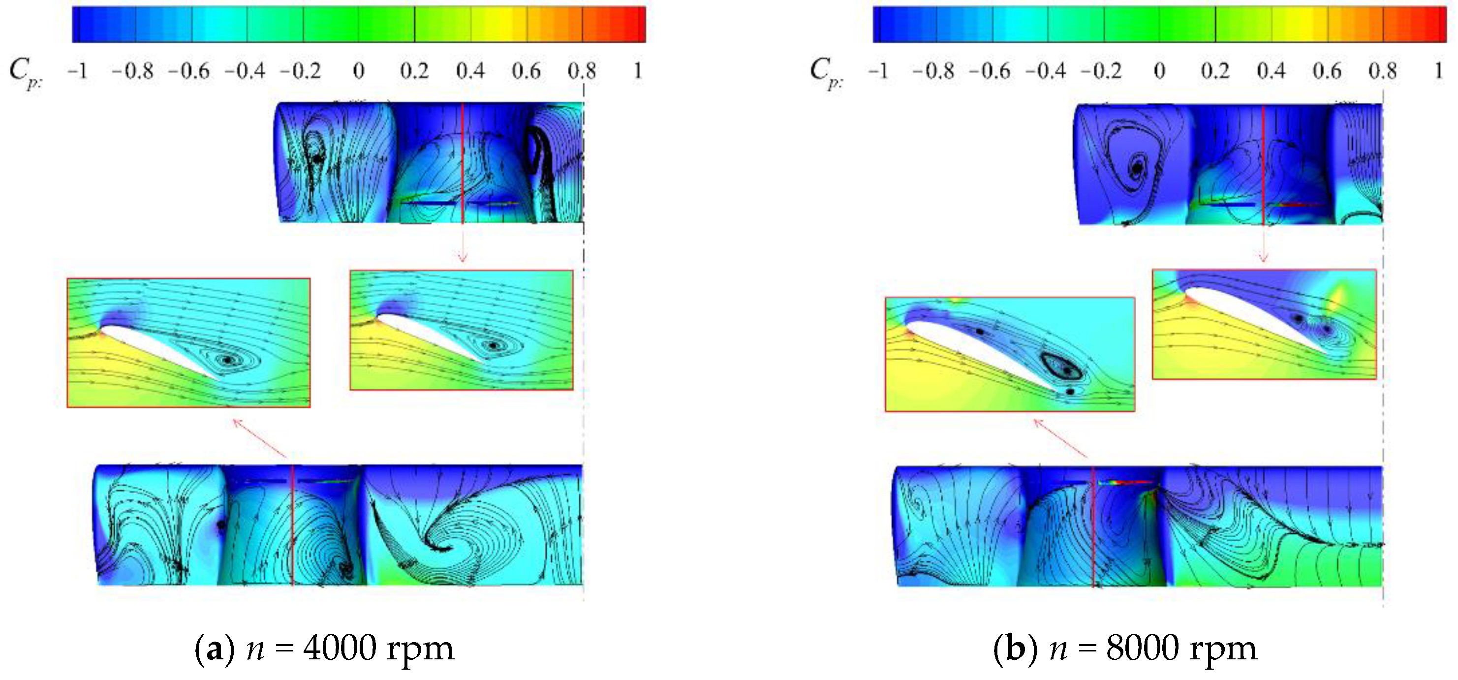
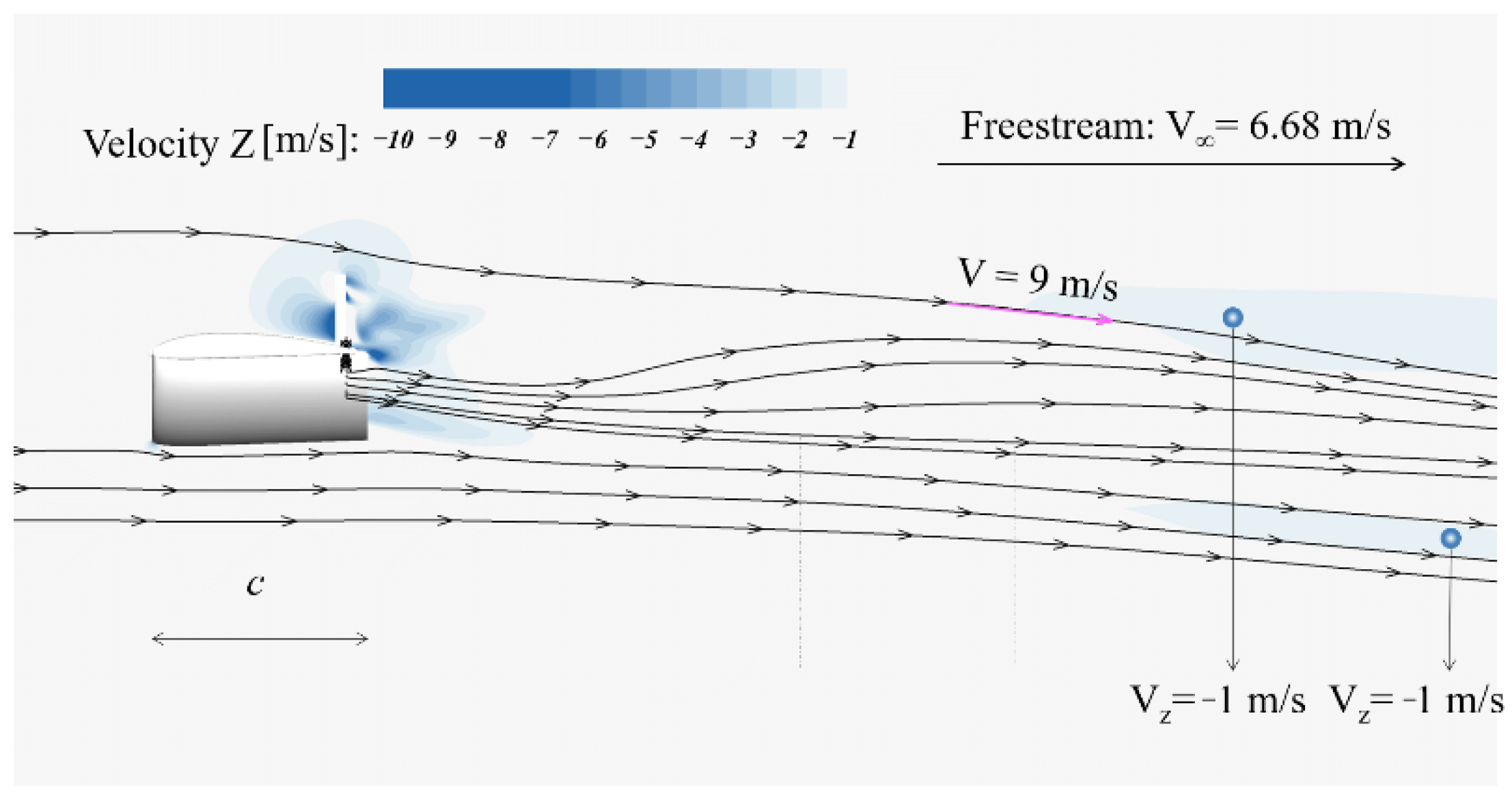
Under the FLR configuration, the rear wing is impacted by the downwash effect of the front wing, which decreases the local angle of attack and delays airflow separation on the top surface. In the FUR configuration, the rear wing top surface is induced by the wake flow of the front wing propeller at a high speed, which increases the lift force, the total lift force, and the stall angle of attack; however, the aircraft tends to be statically unstable at this moment.
eVTOL aircraft have developed rapidly, and a variety of configurations are being tested. The configurations developed in this paper and the analysis can be used as references, providing a new choice for urban aircraft. In the future, the coupling analysis between vehicle drag and propeller characteristics will be analyzed. What is more, a propeller–wing coupling aerodynamic optimization design will be determined.

Author Contributions

Conceptualization, M.C., Z.Z., X.M., J.B. and B.W.; methodology, X.M. and Z.Z.; writing—original draft preparation, Z.Z.; writing—review and editing, Z.Z. All authors have read and agreed to the published version of the manuscript.

Funding

The work is funded by National Natural Science Foundation of China (No. 11902320). The Central Government Guides Local Funds for Science and Technology Development (No. 2021Szvupl), and Youth Innovation Promotion Association CAS (No. 2020149). Additionally, the work is supported by the Fundamental Research Funds for the Central Universities.

Data Availability Statement

Not applicable.

Conflicts of Interest

The authors declare no conflict of interest. The funders had no role in the design of the study; in the collection, analyses, or interpretation of data; in the writing of the manuscript; or in the decision to publish the results.

References

  1. Holden, J.; Goel, N. Fast-Forwarding to a Future of On-Demand Urban Air Transportation; Uber Elevate: San Francisco, CA, USA, 2016. [Google Scholar]
  2. Thipphavong, P.; Apaza, R.; Barmore, B.; Battiste, V.; Burian, B.; Dao, Q.; Feary, M.; Go, S.; Goodrich, K.H.; Homola, J.; et al. Urban air mobility airspace integration concepts and considerations. In Proceedings of the 2018 Aviation Technology, Integration, and Operations Conference, Atlanta, GA, USA, 25–29 June 2018; AIAA: Reston, VA, USA, 2018; pp. 3676–3681. [Google Scholar]
  3. Balakrishnan, K.; Polastre, J.; Mooberry, J.; Golding, R.; Sachs, P. Blueprint for the Sky. The Roadmap for the Safe Integration of Autonomous Aircraft; Airbus A3: Santa Clara Valley, NC, USA, 2018. [Google Scholar]
  4. Embraer, X. Flight Plan 2030: An Air Traffic Management Concept for Urban Air Mobility; Duskamp; EmbraerX: Sao Jose Dos Campos, Brazil, 2019. [Google Scholar]
  5. Lascara, B.; Spencer, T.; DeGarmo, M.; Lacher, A.; Maroney, D.; Guterres, M. Urban Air Mobility Landscape Report; MITRE: McLean, VA, USA, 2018. [Google Scholar]
  6. Xu, H.X. The Future of Transportation: White Paper on Urban Air Mobility Systems; EHang: Guangzhou, China, 2020. [Google Scholar]
  7. Menouar, H.; Guvenc, I.; Akkaya, K.; Uluagac, A.S.; Kadri, A.; Tuncer, A. UAV-enabled intelligent transportation systems for the smart city: Applications and challenges. IEEE Commun. Mag. 2017, 55, 22–28. [Google Scholar] [CrossRef]
  8. Gokce, Z.O.; Camci, C. Channel wing as a potential VTOL/STOL aero-vehicle concept. Recent Pat. Mech. Eng. 2010, 3, 18–31. [Google Scholar]
  9. Pasamanick, J. Langley Full-Scale-Tunnel Tests of the Custer Channel Wing Airplane; National Advisory Committee for Aeronautics: Washington, DC, USA, 1953.
  10. Edgington, W. A Lifting Line Analysis of Nonplanar Wings (Numerical Relationship of Spanwise Circulation Distribution to Induced Velocity at Specific Spanwise Station). Ph.D. Thesis, Xerox University Microfilms, Ann Arbor, MI, USA, 1973. [Google Scholar]
  11. Nangia, R.; Palmer, M. “Channel” and “arc” wing aerodynamics with propeller effects for STOL application. In Proceedings of the 39th Aerospace Sciences Meeting and Exhibit, Reno, NV, USA, 8–11 January 2001. [Google Scholar]
  12. Englar, R.J.; Campbell, B.A. Development of pneumatic channel wing powered-lift advanced superSTOL aircraft. In Proceedings of the 1st Flow Control Conference, St. Louis, MO, USA, 24–26 June 2002; p. 3275. [Google Scholar]
  13. Englar, R.J.; Campbell, B.A. Experimental development and evaluation of pneumatic powered-lift super-STOL aircraft. In Proceedings of the 2004 NASA/ONR Circulation Control Workshop, Part 1; NASA: Hampton, VA, USA, 2005. [Google Scholar]
  14. Müller, L.; Kozulovic, D.; Hepperle, M.; Radespiel, R. Installation Effects of a Propeller Over a Wing with Internally Blown Flap. In Proceedings of the 30th AIAA Applied Aerodynamics Conference, New Orleans, LA, USA, 25–28 June 2012; p. 3335. [Google Scholar]
  15. Müller, L.; Kozulovic, D.; Hepperle, M.; Radespiel, R. The Influence of the propeller position on the aerodynamics of a channel wing. AIAA J. 2012, 38, 784–792. [Google Scholar]
  16. Müller, L.; Heinze, W.; Kožulović, D.; Hepperle, M.; Radespiel, R. Aerodynamic installation effects of an over-the-wing propeller on a high-lift configuration. J. Aircr. 2014, 51, 249–258. [Google Scholar] [CrossRef]
  17. Keane, P.; Keane, A.J. Use of Custer Channel Wings–Wing Ducts on Small UAVs. J. Aerosp. Eng. 2016, 29, 04015059. [Google Scholar] [CrossRef]
  18. Shafie, M.A.M.; Hamid, M.F.A.; Rafie, A.S.M. Circulation Control Aircraft Design: Assessment on the Channel-Wing Lift-Thrust Performance Characteristics. J. Adv. Res. Fluid Mech. Therm. Sci. 2019, 64, 143–151. [Google Scholar]
  19. Cravero, C.; Marsano, D. Computational Investigation of the Aerodynamics of a Wheel Installed on a Race Car with a Multi-Element Front Wing. Fluids 2022, 7, 182. [Google Scholar] [CrossRef]
  20. Fernandez-Gamiz, U.; Gomez-Mármol, M.; Chacón-Rebollo, T. Computational Modeling of Gurney Flaps and Microtabs by POD Method. Energies 2018, 11, 2091. [Google Scholar] [CrossRef] [Green Version]
  21. Basso, M.; Cravero, C.; Marsano, D. Aerodynamic Effect of the Gurney Flap on the Front Wing of a F1 Car and Flow Interactions with Car Components. Energies 2021, 14, 2059. [Google Scholar] [CrossRef]
  22. Menter, F.R. Two-Equation Eddy-Viscosity Turbulence Models for Engineering Applications. AIAA J. 1994, 32, 1598–1605. [Google Scholar] [CrossRef]
  23. Luo, J.; Gosman, A. Prediction of Impeller-Induced Flow in Mixing Vessels Using Multiple Frames of Reference. Inst. Chem. Eng. Symp. Ser. 1994, 136, 549–556. [Google Scholar]
  24. Ghoddoussi, A.; Miller, L.S. A More Comprehensive Database for Low Reynolds Number Propeller Performance Validations; American Institute of Aeronautics and Astronautics, Inc.: Washington, DC, USA, 2016; p. 3422. [Google Scholar]
  25. Droandi, G.; Syal, M.; Bower, G. Tiltwing Multi-Rotor Aerodynamic Modeling in Hover, Transition and Cruise Flight Conditions. In Proceedings of the 74th Annual Forum, Phoenix, AZ, USA, 14–17 May 2018. [Google Scholar]
Figure 1. The schematic diagram of regional division.
Energies 15 08616 g001
Figure 2. Geometry of a propeller with nacelle.
Energies 15 08616 g002
Figure 3. Pressure distribution in different meshes.
Energies 15 08616 g003
Figure 4. The grid used for simulations. (a) Static domain grids. (b) Rotational domain grids. (c) Combined grids.
Energies 15 08616 g004
Figure 5. Comparison with wind tunnel test data.
Energies 15 08616 g005
Figure 6. Sketch of a channel wing and its grid. (a) Size of a channel. (b) The grid for simulating.
Energies 15 08616 g006
Figure 7. The wake downwash velocity diagram of a channel wing.
Energies 15 08616 g007
Figure 8. Sketch of a channel wing with a rear propeller and its grid. (a) Size of a channel with a rear propeller. (b) The grid for simulating.
Energies 15 08616 g008
Figure 9. The wake downwash velocity diagram of a channel wing with rear propeller.
Energies 15 08616 g009
Figure 10. The aircraft with tandem-wing layout.
Energies 15 08616 g010
Figure 11. Sketch of the FLR configuration.
Energies 15 08616 g011
Figure 12. Sketch of the FUR configuration.
Energies 15 08616 g012
Figure 13. Mesh of the FLR configuration: (a) rotational domain; (b) stational domain.
Energies 15 08616 g013
Figure 14. Lift, drag and moment coefficients at different propeller rotational speeds.
Energies 15 08616 g014
Figure 15. Wingspan lift distribution at different propeller rotational speeds.
Energies 15 08616 g015
Figure 16. Surface pressure distribution at (a) n = 4000 rpm and (b) n = 8000 rpm.
Energies 15 08616 g016
Figure 17. Interference of the front wing wake to the rear wing.
Energies 15 08616 g017
Figure 18. Lift and moment coefficients at different angles of attack.
Energies 15 08616 g018
Figure 19. Lift coefficient of each component at different angles of attack.
Energies 15 08616 g019
Figure 20. Flow field at the symmetric plane of the ring wing corresponding to different propeller rotational speeds at a 24° angle of attack. (a) n = 4000 rpm. (b) n = 8000 rpm.
Energies 15 08616 g020
Figure 21. Flow field in the inner wing of the rear wing at the symmetry plane of the front ring wing. (a) unpowered; (b) n = 4000 rpm; (c) n = 8000 rpm.
Energies 15 08616 g021
Figure 22. Mesh of the FUR configuration: (a) rotational domain; (b) stational domain.
Energies 15 08616 g022
Figure 23. Lift and moment coefficients at different propeller rotational speeds.
Energies 15 08616 g023
Figure 24. Wingspan lift distribution at different rotational speeds.
Energies 15 08616 g024
Figure 25. Surface pressure distribution at 4000 rpm and 8000 rpm.
Energies 15 08616 g025
Figure 26. Spatial velocity distributions for n = 4000 rpm and n = 8000 rpm.
Energies 15 08616 g026
Figure 27. The velocity and pressure distribution of the rear inner wing at the symmetry plane of the front ring wing.
Energies 15 08616 g027
Figure 28. Lift and moment characteristics at different angles of attack.
Energies 15 08616 g028
Figure 29. Lift coefficient of each component at different angles of attack.
Energies 15 08616 g029
Figure 30. Pressure distribution on the upper surface and the two-dimensional flow field at the symmetry plane of the semiring wing.
Energies 15 08616 g030
Table 1. Mesh description.
MeshΔy1y1+Grid Cells
A3 × 10−611,000,000
B1 × 10−60.44,000,000
C3 × 10−70.1132,000,000
Table 2. Geometric parameters of the two configurations.
ParameterFLR ConfigurationFUR Configuration
Span of front wing2000 mm2000 mm
Span of rear wing3200 mm3200 mm
Radius of propeller200 mm200 mm
Distance along chordwise1600 mm1600 mm
Distance along vertical−300 mm300 mm
Publisher’s Note: MDPI stays neutral with regard to jurisdictional claims in published maps and institutional affiliations.

