Article

Magnet Slotting Design to Reduce High Order Electromagnetic Force and Vibration of Permanent Magnet Motor

School of Electrical and Information Engineering, Jiangsu University, Zhenjiang 212013, China
*
Author to whom correspondence should be addressed.
Energies 2022, 15(22), 8684; https://doi.org/10.3390/en15228684
Submission received: 22 September 2022 / Revised: 13 November 2022 / Accepted: 15 November 2022 / Published: 18 November 2022

Abstract

:
In this paper, a new method is proposed to suppress the vibration caused by the modulation effect of high-order electromagnetic forces in permanent magnet (PM) motors. Firstly, the modulation effect of the radial force was investigated, which indicated that the higher-order electromagnetic force could cause modulated vibrations through the modulation effect. Then, auxiliary slots on the magnet surface and their effect on vibration reduction were investigated. The optimal shape of the auxiliary slot was found to minimize the noise of motor vibration. Finally, the method was verified experimentally.

1. Introduction

The vibration and noise performance of permanent magnet (PM) motors directly affects their operational performance indicators, with consequences for, e.g., the stealth and reliability of submarines [1]. In recent years, new nanotechnologies have been widely applied in the electrical field [2]. Nanotechnology motors are unique devices that can be used to create incredibly powerful movement. They are small enough to travel through the smallest spaces and can be controlled using electrical impulses. This technology is still in its early stages, but it has the potential to revolutionize many industries. For example, the thick film ultrasonic micromotors proposed in [3] have promising applications in aerospace, intelligent robotics and other fields. Motors with lower vibration and noise can be applied to various nanomotors, thus promoting the development of each other [4,5]. Therefore, it is of great significance to reduce noise in the design process of PM motors.
The noise of PM motors mainly comes from three aspects: the electromagnetic, aerodynamic and mechanical characteristics. Among them, the latter is mainly caused by poor machining accuracy and improper assembly. Aerodynamic noise is mainly caused by the rotor and fan alternating eddy currents generated by cooling air turbulence on the rotating surface. The most common noise in motors is electromagnetic noise, which is caused by the electromagnetic forces applied to the stator teeth [6]. Since the amplitude of the tangential electromagnetic force is much smaller than that of the radial electromagnetic force in PM motors, the former is usually neglected in noise analyses.
In traditional analyses, the vibration response of PM motors is inversely proportional to the fourth power of the harmonic order of the electromagnetic force; in other words, the lower order electromagnetic force is the main source of acoustic noise. For three-phase winding motors, the lowest order of the electromagnetic force is the greatest common divisor of the number of slots and the number of poles. However, in recent years, with new insights into the modulation effect of the air-gap magnetic field of motors [7], it is believed that the higher-order electromagnetic force of PM motors has a non-negligible effect on motor noise, even surpassing the lower-order electromagnetic force [8,9].
Currently, there are many methods to reduce the vibration noise of permanent magnet motors by reducing the low-order electromagnetic forces [10,11,12,13,14]. In the literature [15,16], slotting on the stator was proposed to reduce noise. The slots changed the distribution of the air-gap magnetic field to reduce the low-order electromagnetic forces. Although higher-order electromagnetic forces were not mentioned, this observation illustrated that noise can be optimized by modifying the magnetic structure of the motor. The authors of [17] analyzed various methods to enhance the performance of motors through magnetic pole optimization and modification of magnetic steel; however, they did not mention any reduction in high-order electromagnetic force. A method was proposed in [18] to improve voice coil motors, which are used in the nano-stage in lithographic equipment, by improving the part of the magnet or the back iron in the motor structure. The authors of [19] proposed the use of slots on the surface of the rotor magnets to reduce the cogging torque but did not apply this method to study vibration and noise. The authors of [20] showed that reducing the higher-order electromagnetic forces can greatly improve the electromagnetic noise of motors. Those authors also proposed a targeted step skewing of rotor segments to reduce the higher-order electromagnetic forces. However, it was shown that the machining of such a rotor is difficult, and that it leads to a decrease in power density. There are few methods to reduce the higher-order electromagnetic forces, most of which reduce the output performance of the motor. In view of the above research, we propose a new method which can not only reduce the vibration noise caused by the high-order electromagnetic force of the motor, but which also brings about no reduction in the output torque.
In this paper, the effect of the higher-order electromagnetic force of PM motors on vibrations is analyzed. Additionally, a 12-slot/14-pole PM motor is taken as an example to study the slotting method of the magnet surface. Thereafter, a sensitivity analysis of various parameters is carried out and the optimal slot type is found by response surface optimization to reduce the higher-order electromagnetic force of the motor, thus greatly reducing noise. The main contribution of this paper is to propose a new method to effectively reduce the higher-order electromagnetic force and ensure satisfactory output performance.

2. Modulated Vibration Source Analysis

In this section, a 12-slot/14-pole motor is taken as a prototype to build a finite element model in order to help visualize the source of modulated vibration and thus verify the mechanism of modulated action of electromagnetic force.
The prototype is a fractional-slot surface-mount PM motor with a housing made of magnesium-aluminum alloy. The PM motor has a rated power of 200 W, a rated speed of 2500 rpm, and a rated output torque of 0.76 Nm. The overall mechanical structure of the PM motor is shown in Figure 1, and its main parameters are shown in Table 1.
Figure 2 shows a schematic diagram of the vibration acceleration on the surface of the permanent magnet motor housing. A model with a load of 0.76 Nm was built based on the parameters of the PM motor, and the PM motor was operated under the rated operating conditions. Then, the nonlinear vibration was analyzed and calculated to obtain the vibration acceleration simulations for the PM motor. Figure 2 shows that the vibration acceleration of the motor at 10fe frequency was much higher than other frequencies, regardless of load, which is the largest source of vibration noise. The most sensitive frequency range of the human ear is about 1 kHz~8 kHz; the 10fe of the PM motor was exactly 2910 Hz, which is within this range.

2.1. Analysis of Radial Electromagnetic Force

In this section, the Maxwell tensor method is used to solve the electromagnetic force, which is analyzed and derived according to the modulation effect of motor slotting. Then, the principle of modulated vibration generation is explained.
Neglecting the tangential electromagnetic force which is much smaller than the radial electromagnetic force, the latter can be expressed according to the Maxwell tensor method as:
F r = B r 2 2 μ 0
where Fr is the radial electromagnetic force, Br is the radial flux density, and μ0 is the vacuum permeability. After introducing the modulation effect of the air-gap magnetic field, the whole air-gap magnetic field can be represented by the modulation function, in accordance with the multiplication method. The final expression of the modulation function of the air-gap magnetic field is:
M θ = M 0 + M k cos kz θ
where M0 is the DC component of the modulation function, the second term in Formula (2) is the AC component, and Mk is the amplitude of the AC component of each order.
The air-gap modulation function interacts with the original magnetic field in a multiplicative manner. Since the electromagnetic force satisfies the Dirichlet condition, for further analysis, a Fourier decomposition of Formula (1) was performed, and then Formula (2) is substituted to obtain:
F r = B r 2 2 μ 0 = 1 2 μ 0 { [ n F n M 0 cos np θ n ω t + k n F n M k 2 cos np θ n ω t ± kz θ ] + [ v F v M 0 cos v p θ ω t φ v + k v F v M k 2 cos v p θ ± k z θ ω t φ v ] } 2
By further extending Formula (3), the source of electromagnetic force can be divided into three parts: the self-interaction of the permanent magnetic field, the self-interaction of the armature magnetic field, and the interaction between the armature magnetic field and the permanent magnetic field. These three electromagnetic force harmonics were extracted to obtain the Table 2:
According to the electromagnetic force frequency formula (vR1 ± vR2) fe in the above table, the electromagnetic force generating a vibration which is 10 times the fundamental frequency requires the difference or the sum of two orders of the magnetic density harmonic is 70. For the spatial order of the radial electromagnetic force, Table 1 shows that the harmonic components of the 10fe/70th order electromagnetic force in the motor mainly come from the (vR1 ± vR2)p harmonics when the PM density acts on itself and the armature magnetic density and (vR1 ± vS) p order harmonics when the armature magnetic density interacts with the PM density. These two kinds of harmonics are also produced by the interaction of flux density harmonics whose order difference or sum is 70. Therefore, the 70th order electromagnetic force is the one that contributes the most to the amplitude at 10 times the frequency.
Figure 3 shows the Fourier decomposition of the air gap flux density. It can be seen that the PM flux density is much higher than the armature flux density, and as such, that the former is the main source of the electromagnetic force. It also can be seen that the interaction between the 7th and 77th order, 7th and 63rd order, 21st and 49th order, and 35th order flux density of the motor is the main cause of the 70th order electromagnetic force at 10 times the frequency. Therefore, in order to achieve a good noise reduction effect, it is necessary to reduce these harmonic components substantially while also ensuring that the fundamental components are not reduced.

2.2. Generation of Modulation Vibrations

In a motor comprising a hollow cylinder without slotting, the vibration response can be expressed as:
A m F m m 2 1 2 1 1 f f c 2 ¯
According to Equation (4), the vibration response of a motor is inversely proportional to the fourth power of the spatial harmonic order of the electromagnetic force. However, as described in Section 2.1, the motor vibrates maximally at 10fe. According to the 2DFFT of the radial electromagnetic force shown in Figure 4, the maximum amplitude of the electromagnetic force at 10 times the frequency is much smaller than those at 2fe, 4fe and 6fe. The small amplitude of the electromagnetic force causes large vibrations, which seems to violate Equation (4).
The reason for this is that the effect of the slotting should be considered in the analysis. According to the Nyquist Shannon sampling theorem, if the sampling frequency is greater than half of the fundamental frequency, an aliasing effect will occur. If the motor stator is slotted, and if the harmonic order of the electromagnetic force is greater than half the number of slots in the motor, the higher-order electromagnetic force will be sampled by each stator tooth and modulated into a lower-order vibration response. As shown in Figure 5, the 14th-order electromagnetic force will be modulated into second-order vibrations after being sampled by 12 stator slots. In Figure 5, the red line represents the second-order electromagnetic force, and the blue line represents the 14th-order electromagnetic force.
The electromagnetic force of higher order (vR1 ± vR2) p, (vS1 ± vS2) p and (vR ± vS) p will change to (vR1 ± vR2) P ± kZ, (vS1 ± vS2) P ± kZ, and (vR ± vS) P ± kZ. At the same frequency, the amplitude of these electromagnetic forces is the maximum, so the contribution of these forces on the vibrations will be amplified after being modulated.

3. Research on Modulation Vibration Optimization Method

From the above analysis, it can be seen that modulated vibration has the greatest effect on the vibration noise of PM motors, and that the PM flux of the motor has the greatest effect on the electromagnetic force. Therefore, a method needs to be proposed to reduce the higher-order electromagnetic force generated by the interaction of PM fluxes. In this section, a new method to reduce the modulated vibration is presented.

3.1. Principle of Analysis

In this section, the principle of air-gap magnetic density harmonic reduction by the permanent magnet slotting method is qualitatively analyzed based on the source of the magnetomotive force (MMF) generated by permanent magnets.
Figure 6 shows a schematic diagram of the slotting on the surface of permanent magnets. The source of the air-gap magnetic density in the motor is mainly the MMF of the permanent magnet [21]. In order to fundamentally change the harmonics of the air-gap magnetic density, it is necessary to change the MMF of the permanent magnets. To conveniently study the changes in the permanent magnets after slotting, the magnetic circuit components of the motor were equivalent to those in the circuit diagram. As shown in Figure 7, the magnetic circuit of the motor can be viewed as MMF source Fm and the external magnetic circuit. MMF source Fm can be viewed as constant MMF source Fc and an internal permeability λ0.
A permanent magnet MMF source can be expressed as
F m = F c Φ m Λ 0
A constant MMF source can be expressed as
F c = H c h Mp × 10 2
The magnetic conductivity in the permanent magnet can be expressed as:
Λ 0 = μ r μ 0 A m h Mp × 10 2
where hMp is the magnetizing length of the permanent magnet and Am is the cross-sectional area of the magnetic flux of each permanent magnet pole:
F c = μ F μ cos ( μ ω t μ p θ )
where the MMF amplitude is:
F μ = 4 μ π Bh Mp μ 0 sin ( μ α p π 2 )
In the above formula, μr is the relative recovery permeability, μ0 is the vacuum permeability, B is the remanence of the permanent magnet, and αp is the polar arc coefficient. Obviously, the amplitude of the MMF is proportional to the magnetization length. As shown in Figure 8, after slotting, the amplitude of the MMF at the slotting will decrease, thus affecting the distribution of harmonics of all orders. In Figure 8, the orange, red, and blue lines represent the first harmonic, third harmonic, and fifth harmonic, respectively, and the numbers represent their harmonic orders. The dotted line represents the decrease in harmonics of different orders after slotting.
Since the permanent magnets of the motor are magnetized in parallel, different slots will lead to uneven variations in the magnetization length of the magnets, which will affect the reduction of the harmonic order of the magneto-motor and consequently the magnetic density, as shown in Figure 9.
It can be clearly seen that the variation of the magnetizing length at h1 is different and asymmetrical from that at h2. Therefore, the shape of the slots is of great importance to the harmonic of the magnetomotive force. The formula for PM flux density is:
B m = F r × Λ
Since the permeability of the permanent magnet is approximately the same as that of the air gap, changes therein can be neglected after slotting, and the harmonics of the air gap flux density will increase or decrease with changes in MMF. As shown in the electromagnetic force analysis in Section 2.1, the variation of air-gap flux density harmonics affects the distribution of electromagnetic force.
According to the qualitative analysis above, the most suitable approach may be to reduce the air-gap flux density harmonics which significantly affect the vibration by changing the position and width of auxiliary slot on the surface of the permanent magnet while also ensuring that the flux density harmonic which contributes the most to the output torque does not decrease significantly. To improve the feasibility of the method, two auxiliary slots were cut into the surface of the permanent magnet. The shape of the auxiliary slots was semi-circular in order to facilitate processing. Since the theory of the slotting equation is complex, the response surface optimization algorithm is presented below to determine the most appropriate slot shape to minimize the electromagnetic force harmonics with the greatest effect on vibration noise.

3.2. Auxiliary Slot Shape Optimization

To further optimize the motor, the following procedure was applied. The electromagnetic force calculated by the finite element method was used as the excitation source for the harmonic response analysis, which was applied to the top of the stator teeth, and the vibration acceleration of the motor shell surface was used as the response. During the finite element calculation of the electromagnetic force, the average output torque of the motor could be calculated at the same time.
The main process of the optimization simulation is shown in Figure 10. In order to obtain better optimization results, an optimization algorithm can be used [22]. The width and position of the auxiliary slot were extracted as independent variables. The vibration acceleration and output torque of the permanent magnet motor were used as optimization target parameters. All the above parameters were added to the response surface parameter construction and optimized by the response surface.
To make the response surface more accurate, it was optimized iteratively by continuously adding validation points. Inaccurate validation points then served as refinement points. Finally, a response surface with a more accurate response effect for the given parameters could be fitted as shown in Figure 11.
After the iterative optimization of the response surface, the optimal solutions were simulated separately, and the results were basically consistent. This indicated that the response surface was well fitted and that the optimal solutions obtained were plausible.
The optimal auxiliary slot shape parameters obtained from the response surface were as follows: the inclusion angle of slot 1 was 10.75° and the width of slot 1 was 0.37 mm; the inclusion angle of slot 2 was 12.44° and the width of the slot was 0.46 mm. The shape of the auxiliary slot is shown in Figure 12.

3.3. Results Analysis

As shown in Figure 13, the harmonic reduction in the flux density of the permanent magnets at each order was obvious after optimizing the slotting on the surface of the permanent magnets. The reduction was 9.4% for the 21st order, 33.88% for the 35th order, 67.9% for the 49th order, 68.1% for the 63rd order, and 29.5% for the 77th order.
Figure 14 shows a harmonic comparison of the electromagnetic force of each order at 10fe with slotting on the surface of the permanent magnet. As shown, the 70th order electromagnetic force was reduced by 69%, which is in line with the analysis in Section 2.1, in the sense that the radial electromagnetic force mainly comes from the magnetic flux density of the motor permanent magnet.
Figure 15 shows that the vibration acceleration decreased substantially at the 10fe frequency. This result verifies the correctness of the analysis in Section 2.2, i.e., the higher-order electromagnetic force was modulated into a lower-order vibration response, resulting in modulated vibration. Therefore, weakening the higher-order electromagnetic force wave can reduce the vibration noise. As shown in Figure 16, the output torque of the motor did not decrease. The advantage of this method is that the noise is greatly reduced while the output torque is guaranteed. In addition, this result also verified our theoretical analysis.

3.4. Comparison of the Proposed and Traditional Methods

Traditional methods to improve motor noise by reducing electromagnetic force, such as targeted step skewing of the rotor segments and skewing the slot, have some shortcomings.
Although the high order electromagnetic force of the motor can be greatly reduced, the machining technology for the targeted step skewing of rotor segments is very complex, resulting in a significant increase in machining costs.
The processing and winding of the stator skew teeth are difficult, and there is a significant loss of output torque performance. Additionally, the performance characteristics of the stator teeth from the same batch of motors are often inconsistent after skewing.
The method proposed in this paper is applicable to any slot-pole matching motor, especially for noise reduction improvement of existing motors. The processing method is simple and easy to implement. In addition, the method can partly reduce the weight of the motor and requires the use of fewer materials. Other elements of the method merit study, such as slotting magnets of different shapes, variations in the number of slotted magnets, simultaneous slotting of the stator and rotor, etc., all of which should explored in the future.

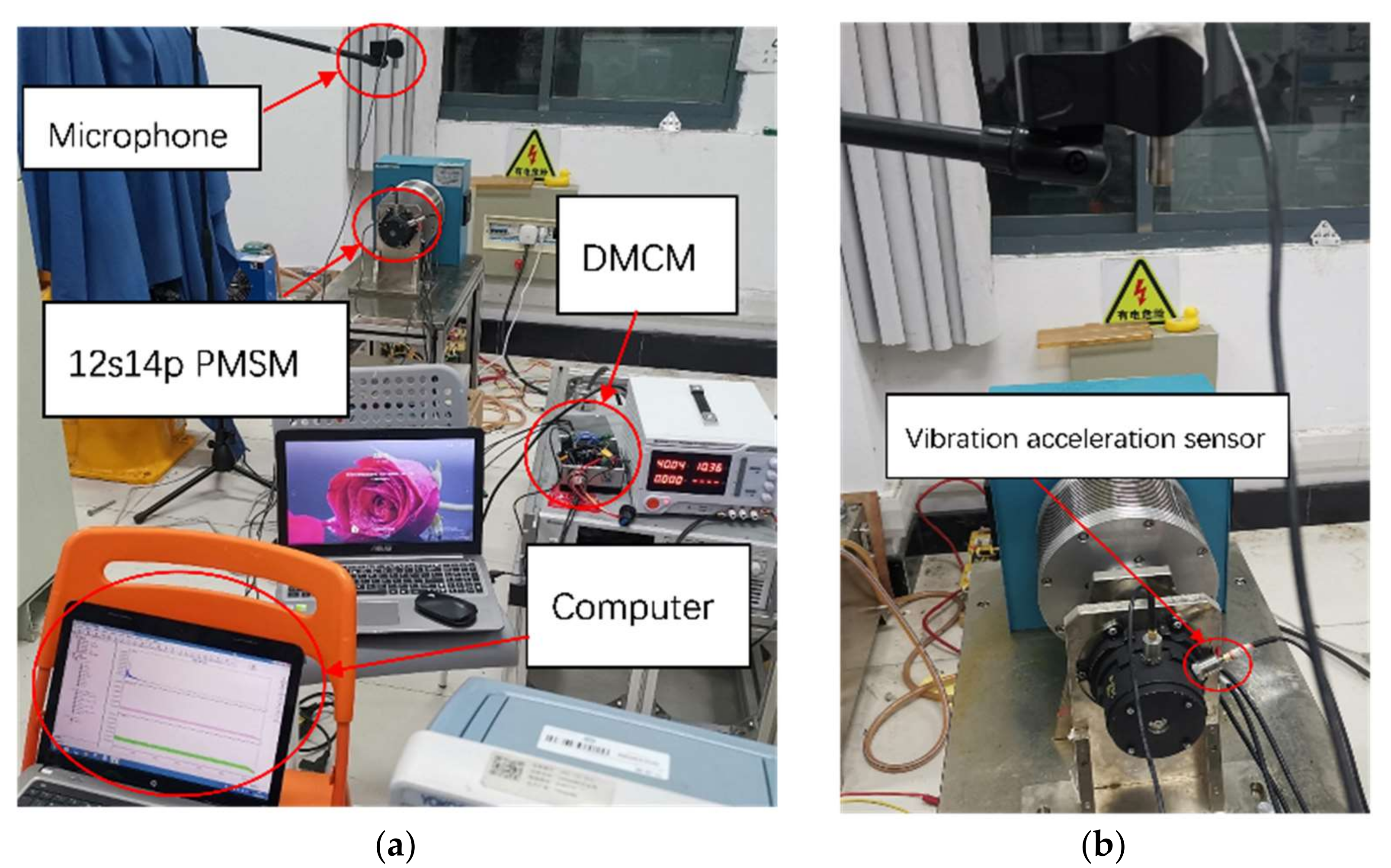
4. Experimental Verification

In order to verify the accuracy of the above analysis and optimization method, the noise and vibration acceleration of the prototype were measured. Figure 17 shows a picture of the PM motor used in this study, and Figure 18 shows field pictures of the noise and vibration acceleration of that motor. A vibration acceleration sensor was fixed to the surface of the motor and the motor was fixed to an eddy current dynamometer. Then, a load of 0.76 Nm was applied, and a microphone was placed more than 20 cm above the motor. The motor was run under rated conditions and the signals from the microphone and accelerometer were transmitted to a computer and recorded in real time.

5. Conclusions

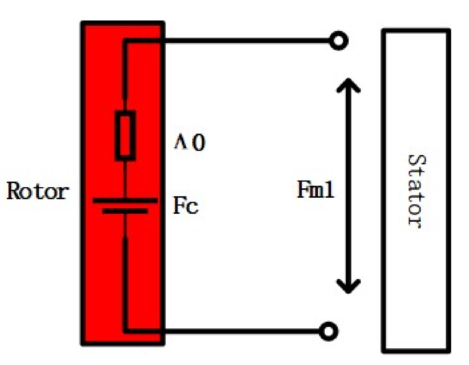
  • The source of the electromagnetic force may be classified into three parts: the self-interaction of the permanent magnetic field, the self-interaction of the armature magnetic field, and the interaction between the armature magnetic field and the permanent magnetic field.The modulation effect of the electromagnetic force was investigated and the results showed that after adding slots to the motor stator, the higher-order electromagnetic force modulated to a lower-order vibration response, leading to significant vibrations.
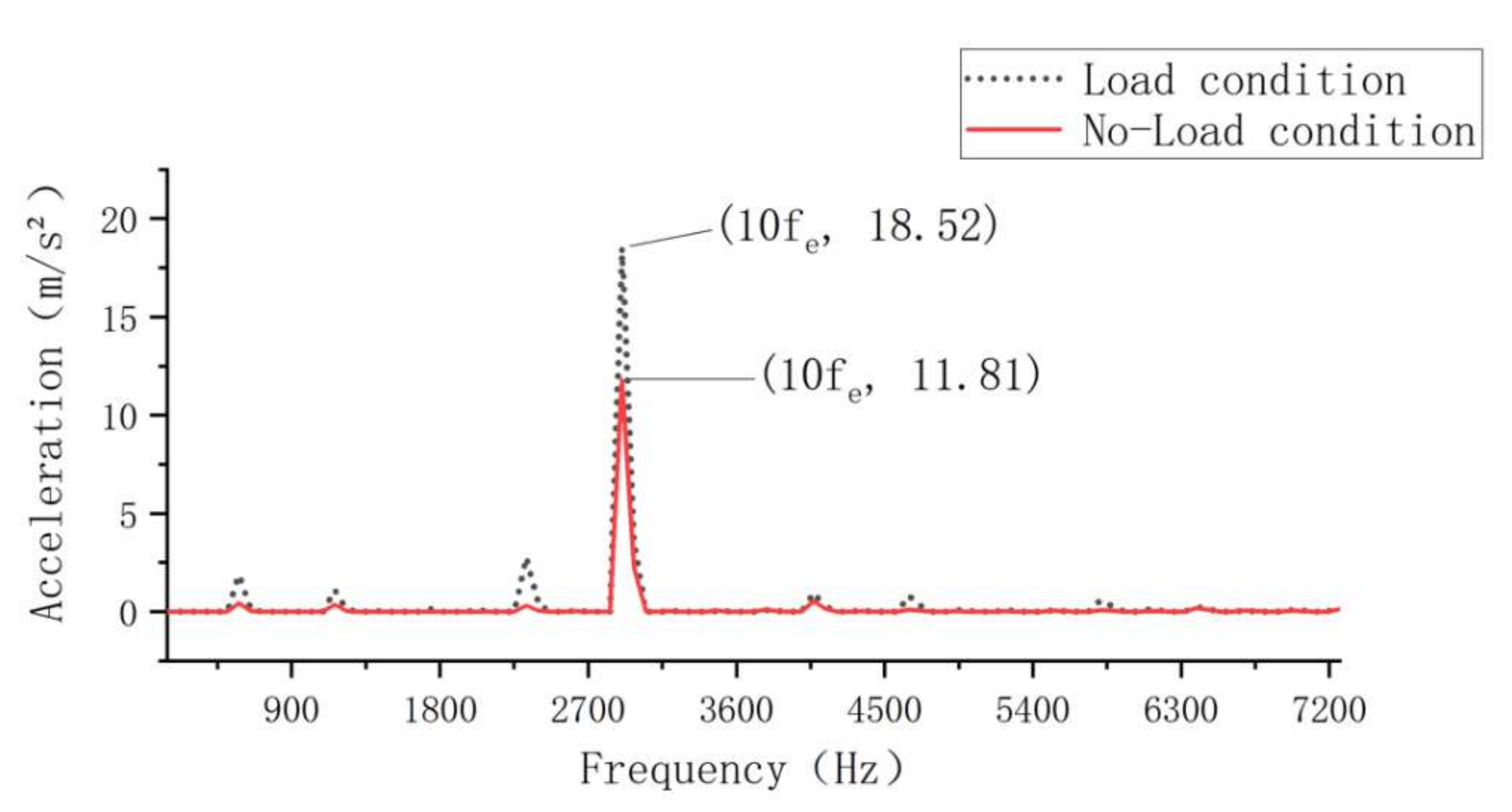
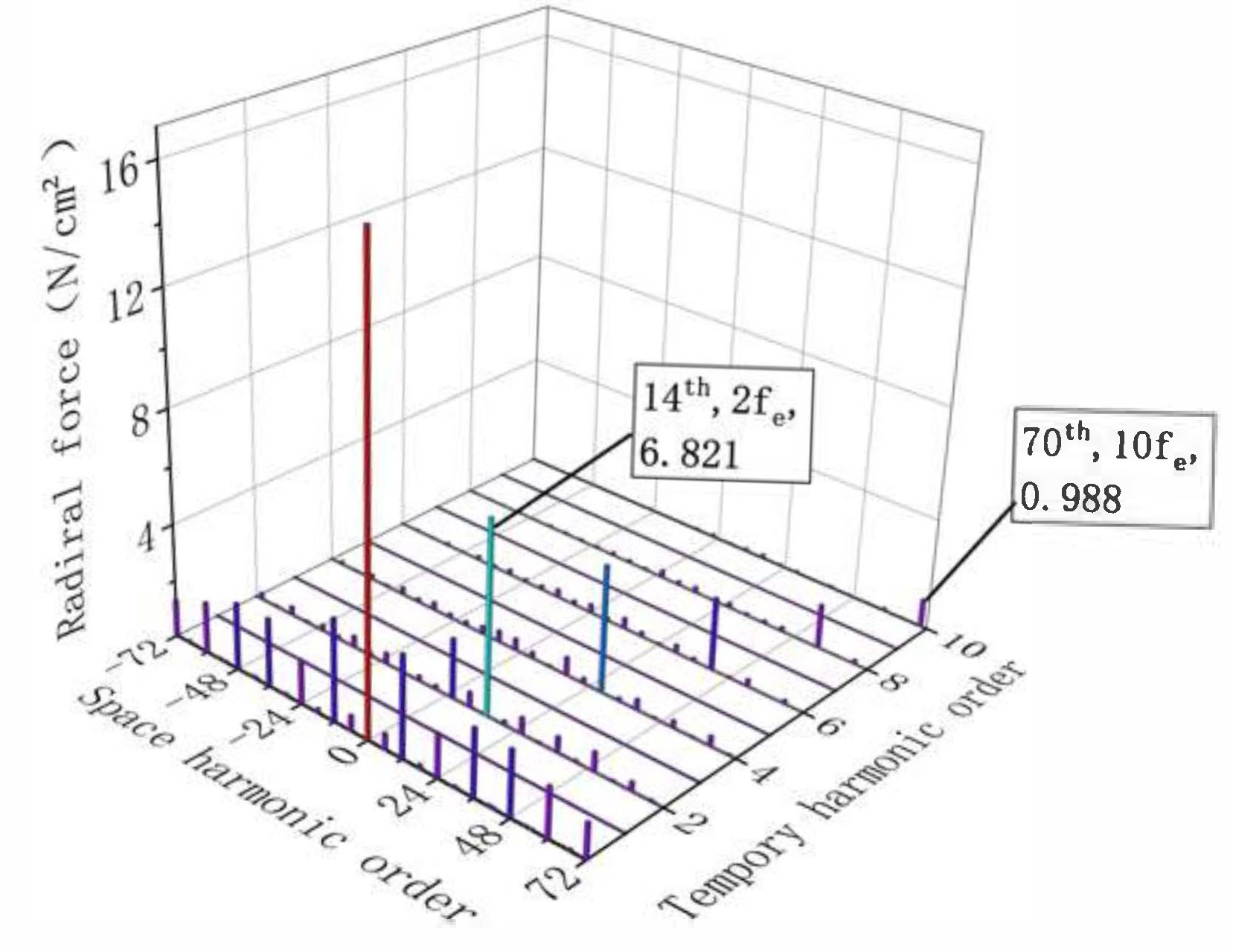
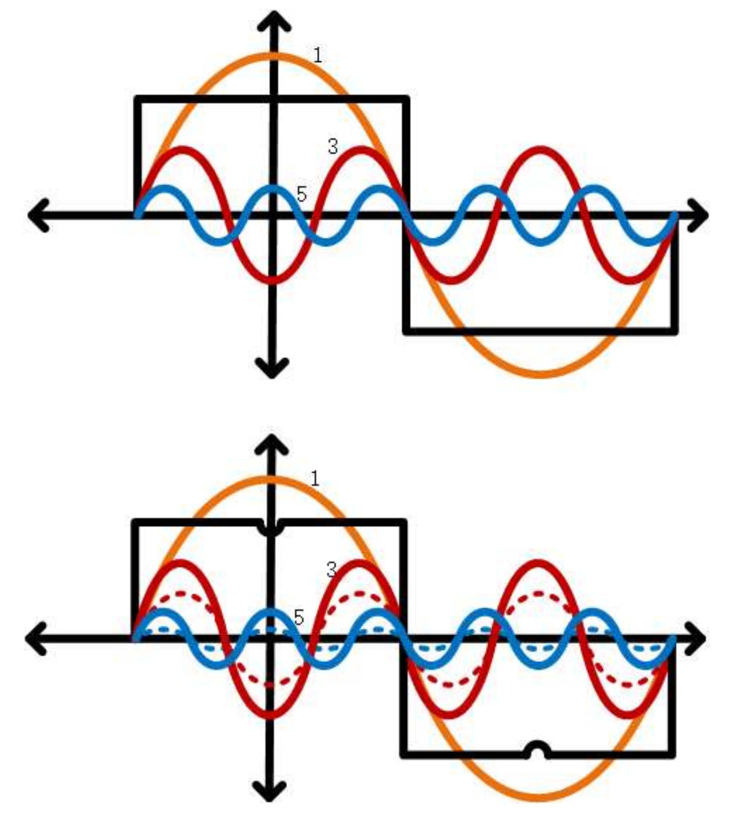
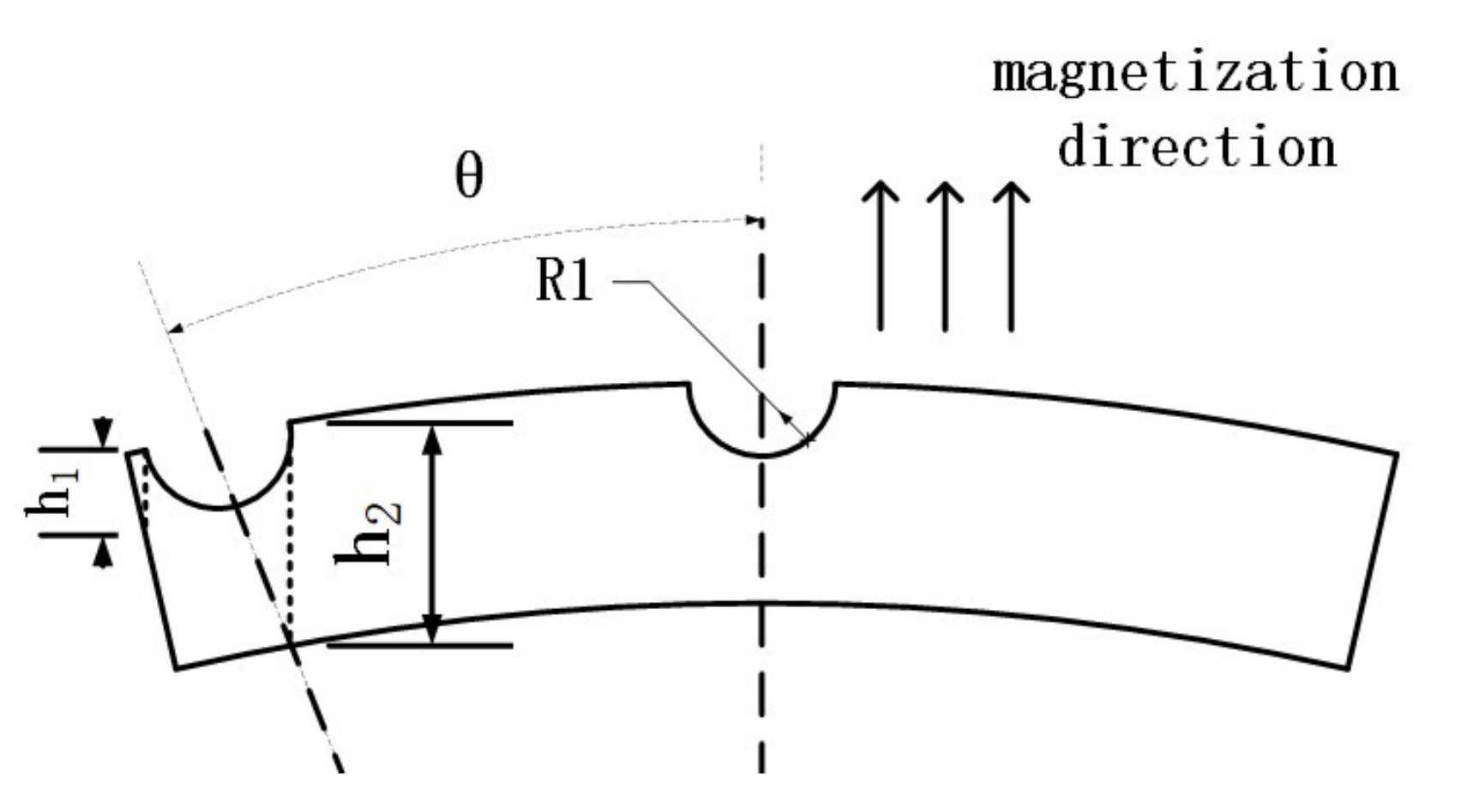
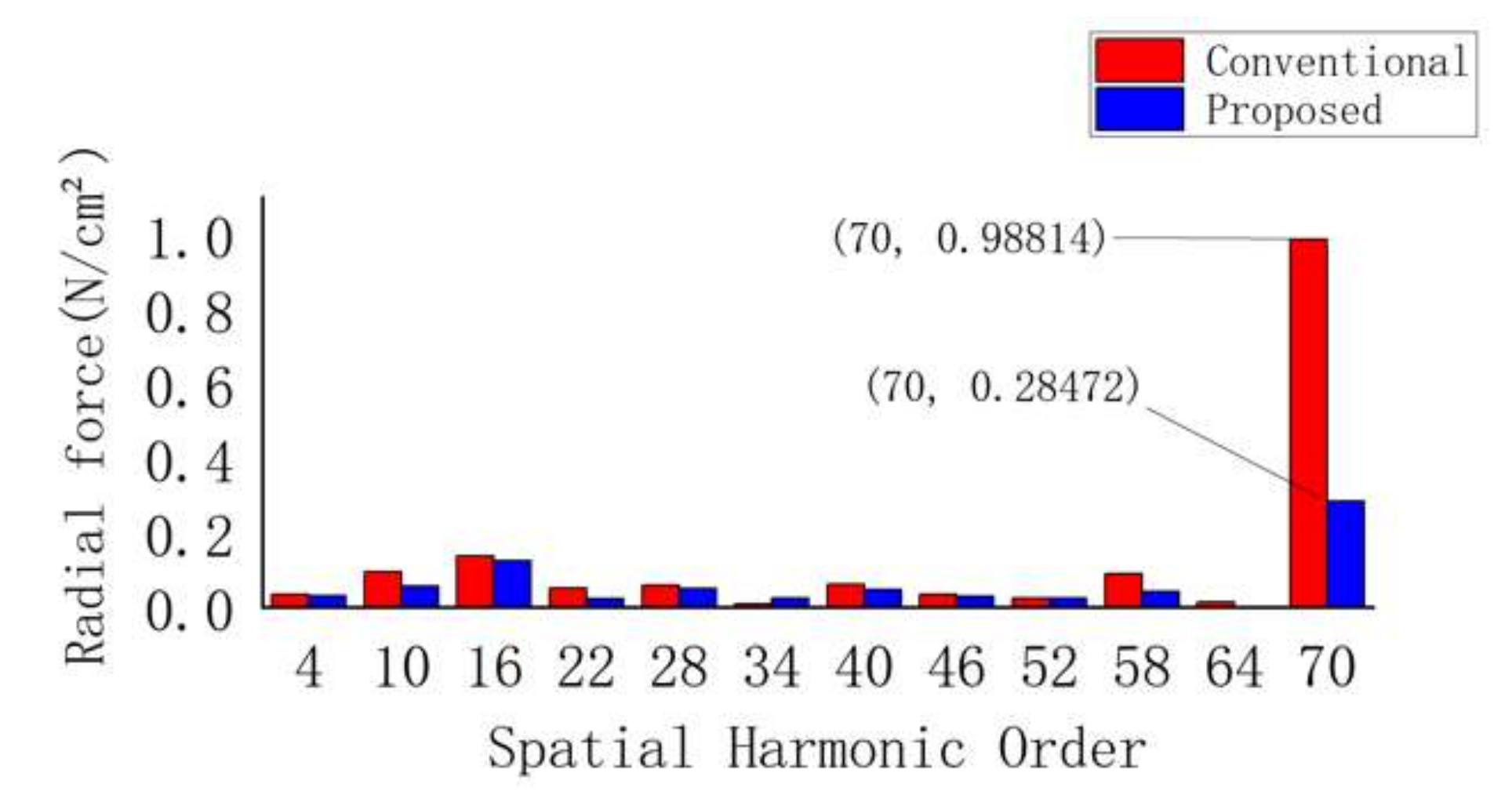
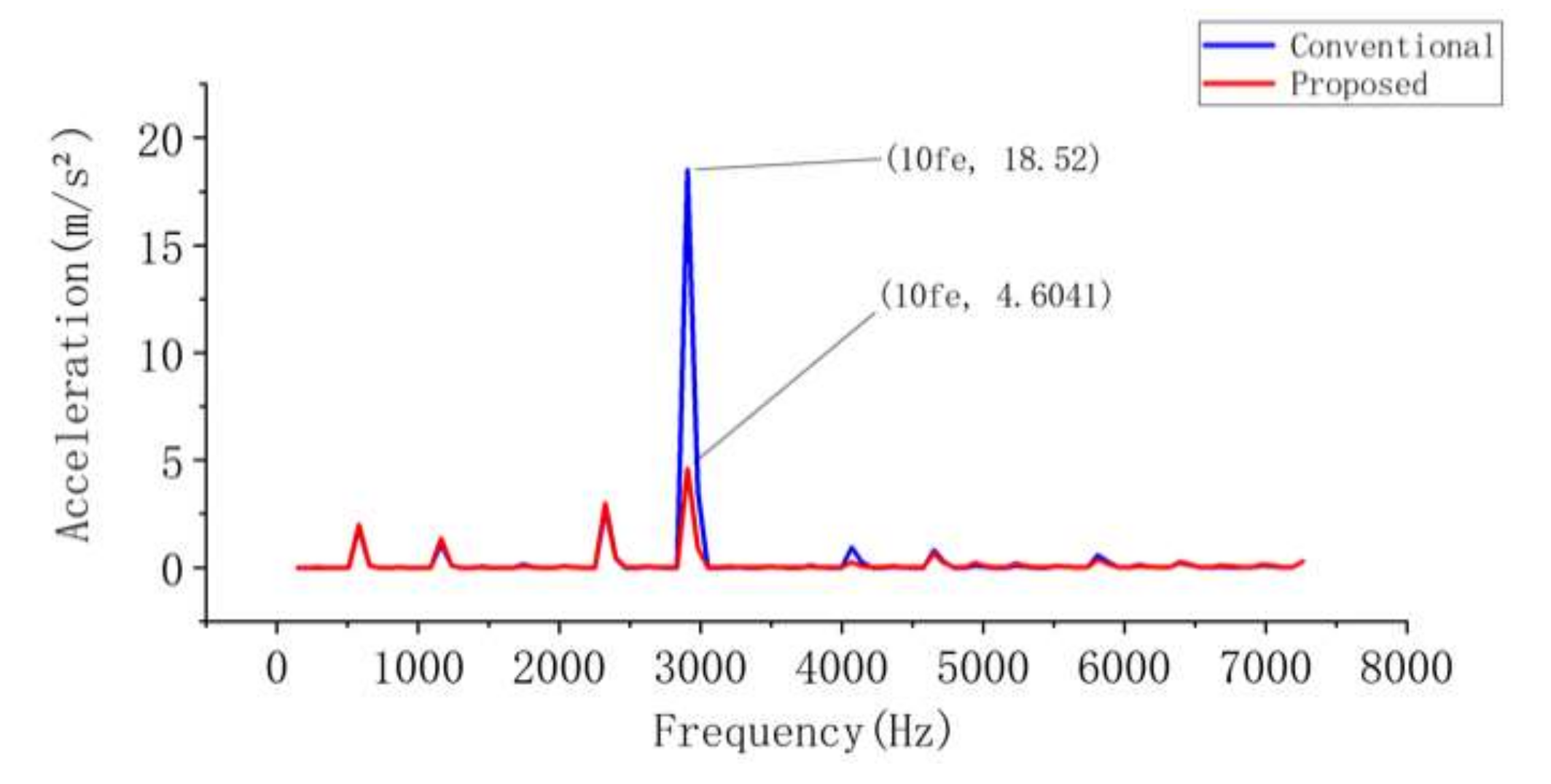
  • A new method of slotting on the surface of permanent magnets was proposed to reduce the higher order electromagnetic force of PM motors. Further, the principle of permanent magnet slotting to reduce flux density harmonics was qualitatively analyzed. It was found that varying the auxiliary slotting parameters leads to variations of each order of flux density harmonics. Finally, the optimal slotting noise reduction method was found by optimizing the slotting parameters. After slotting, the 70th-order electromagnetic force wave at 10fe was greatly reduced, thus reducing the vibration acceleration at 10fe, which has the greatest influence on the motor noise. In addition, this method ensures that the output torque is not significantly decreased.
  • The accuracy of our finite element analysis and the correctness of the noise reduction method were empirically verified.

Author Contributions

Conceptualization, Z.W. and W.T.; methodology, W.Z.; software, Z.W.; validation, W.Z.; formal analysis, W.T.; investigation, Z.W., W.Z. and W.T.; resources, W.Z. and W.T.; data curation, Z.W.; writing—original draft preparation, Z.W.; writing—review and editing, W.Z. and W.T. All authors have read and agreed to the published version of the manuscript.

Funding

This research received no external funding.

Data Availability Statement

Not applicable.

Conflicts of Interest

The authors declare no conflict of interest.

References

  1. Song, C.; Liu, R.; Zheng, W.; Liu, Y. Research on the stealth technology of foreign underwater unmanned mobile vehicle. Ship Sci. Technol. 2021, 43, 186–189. [Google Scholar]
  2. Mohamed, A.T. Emerging Nanotechnology Applications in Electrical Engineering; IGI Global, Publisher of Timely Knowledge: Hershey, PA, USA, 2021. [Google Scholar]
  3. Zhang, P.; Niu, J.; Zhang, X.; Mao, S.; Liu, J.; Yang, B. Thick Film Ultrasonic Micromotor Based on Chemical Mechanical Thinning and Polishing Process. IEEE Electron. Device Lett. 2022, 43, 1547–1550. [Google Scholar] [CrossRef]
  4. Mohamed, A.T. Design and Investment of High Voltage NanoDielectrics; IGI Global, Publisher of Timely Knowledge: Hershey, PA, USA, 2020. [Google Scholar]
  5. Mohamed, A.T. Theoretical analysis for effects of nanoparticles on dielectric characterization of electrical industrial materials. Electr. Eng. ELEN 2017, 99, 487–493. [Google Scholar] [CrossRef]
  6. Dziechciarz, A.; Popp, A.; Marțiș, C.; Sułowicz, M. Analysis of NVH Behavior of Synchronous Reluctance Machine for EV Applications. Energies 2022, 15, 2785. [Google Scholar] [CrossRef]
  7. Cheng, M.; Han, P.; Hua, W. General Airgap Field Modulation Theory for Electrical Machines. IEEE Trans. Ind. Electron. 2018, 64, 6063–6074. [Google Scholar] [CrossRef]
  8. Fang, H.; Li, D.; Qu, R.; Yan, P. Modulation Effect of Slotted Structure on Vibration Response in Electrical Machines. IEEE Trans. Transp. Electron. 2019, 66, 2998–3007. [Google Scholar] [CrossRef]
  9. Zhu, S.; Zhao, W.; Ji, J.; Liu, G.; Mao, Y.; Liu, T. Investigation of Bread-Loaf Magnet on Vibration Performance in FSCW PMSM Considering Force Modulation Effect. IEEE Trans. Transp. Electron. 2021, 7, 1379–1389. [Google Scholar] [CrossRef]
  10. Yang, I.; Lee, S.; Lee, K.; Lee, J.; Kim, W.; Jang, I. A Process to Reduce the Electromagnetic Vibration by Reducing the Spatial Harmonics of Air Gap Magnetic Flux Density. IEEE Trans. Mag. 2021, 57, 1–6. [Google Scholar] [CrossRef]
  11. Hong, J.; Wang, S.; Sun, Y.; Sun, X.; Cao, H. Piecewise Stagger Poles with Continuous Skew Edge for Vibration Reduction in Surface-Mounted PM Synchronous Machines. IEEE Trans. Ind. Electron. 2021, 68, 8498–8506. [Google Scholar] [CrossRef]
  12. Kim, D.; Park, M.; Sim, J.; Hong, J. Advanced Method of Selecting Number of Poles and Slots for Low-Frequency Vibration Reduction of Traction Motor for Elevator. IEEE/ASME Trans. Mech. 2017, 22, 1554–1562. [Google Scholar] [CrossRef]
  13. Zuo, S.; Lin, F.; Wu, X. Noise Analysis, Calculation, and Reduction of External Rotor Permanent-Magnet Synchronous Motor. IEEE Trans. Ind. Electron. 2015, 62, 6204–6212. [Google Scholar] [CrossRef]
  14. Zhu, S.; Zhao, W.; Liu, G.; Mao, Y.; Sun, Y. Effect of Phase Shift Angle on Radial Force and Vibration Behavior in Dual Three-Phase PMSM. IEEE Trans. Ind. Electron. 2021, 68, 2988–2998. [Google Scholar] [CrossRef]
  15. Wu, Z.; Fan, Y.; Lee, C.H.T.; Gao, D.; Yu, K. Vibration Optimization of FSCW-IPM Motor Based on Iron-Core Modification for Electric Vehicles. IEEE Trans. Veh. Technol. 2020, 69, 14834–14845. [Google Scholar] [CrossRef]
  16. Dong, T.; Wang, R.; Zhang, J.; Liu, K. Influence of auxiliary slot on electromagnetic vibration in PMSM with similar slot and pole number. In Proceedings of the 2017 20th International Conference on Electrical Machines and Systems (ICEMS), Sydney, NSW, Australia, 11–14 August 2017; pp. 1–5. [Google Scholar]
  17. Wang, K.; Sun, H.; Zhang, L.; Liu, C.; Zhu, Z. An Overview of Rotor Pole Optimization Techniques for Permanent Magnet Synchronous Machines. Proc. CSEE 2017, 37, 7304–7317+7445. [Google Scholar]
  18. Chi, F.; Wu, L.; Yang, X. Optimum design of voice coil motor using for nano-stage in lithographic equipment. In Proceedings of the 11th World Congress on Intelligent Control and Automation, Shenyang, China, 27–30 June 2014; pp. 2540–2543. [Google Scholar]
  19. Yu, H.; Yu, B.; Yu, J.; Lin, C. A Dual Notched Design of Radial-Flux Permanent Magnet Motors with Low Cogging Torque and Rare Earth Material. IEEE Trans. Mag. 2014, 50, 1–4. [Google Scholar] [CrossRef]
  20. Zhou, Y.; Ji, J.; Zhao, W.; Zhu, S.; Liu, H. Modulated Vibration Reduction Design for Integral-Slot Interior Permanent Magnet Synchronous Machines. IEEE Trans. Ind. Electron. 2022, 69, 12249–12260. [Google Scholar] [CrossRef]
  21. Tang, R. Modern Permanent Magnet Machines: Theory and Design; China Machine Press: Beijing, China, 2016. [Google Scholar]
  22. Wang, Q.; Zhao, P.; Du, X.; Lin, F.; Li, X. Electromagnetic Vibration Analysis and Slot–Pole Structural Optimization for a Novel Integrated Permanent Magnet in-Wheel Motor. Energies 2020, 13, 3488. [Google Scholar] [CrossRef]
Figure 1. 3d internal structure of the PM motor.
Energies 15 08684 g001
Figure 2. Vibration acceleration of the motor under no-load and load conditions.
Energies 15 08684 g002
Figure 3. FFT of the PM motor: (a) PM flux density. (b) Armature flux density.
Energies 15 08684 g003
Figure 4. 2DFFT of radial electromagnetic force.
Energies 15 08684 g004
Figure 5. Schematic diagram of electromagnetic force sampling by stator slot.
Energies 15 08684 g005
Figure 6. Schematic diagram of slotting rotor magnetic steel.
Energies 15 08684 g006
Figure 7. Equivalent magnetic circuit.
Energies 15 08684 g007
Figure 8. Schematic diagram of harmonic changes in magnetomotive force.
Energies 15 08684 g008
Figure 9. Schematic diagram of magnetization length change after slotting.
Energies 15 08684 g009
Figure 10. Optimization flow chart.
Energies 15 08684 g010
Figure 11. Response surface of the PM motor.
Energies 15 08684 g011
Figure 12. Schematic diagram of the final slotting result.
Energies 15 08684 g012
Figure 13. Comparison of flux density harmonics of a permanent magnet.
Energies 15 08684 g013
Figure 14. Electromagnetic force at 10fe frequency of a conventional and the proposed motor.
Energies 15 08684 g014
Figure 15. Vibration acceleration of conventional and proposed machine.
Energies 15 08684 g015
Figure 16. Output torque comparison of conventional and proposed machine.
Energies 15 08684 g016
Figure 17. Picture of the PM motor.
Energies 15 08684 g017
Figure 18. Experimental platform. (a) The arrangement of the experimental equipment. (b) The position of the vibration acceleration sensor. Figure 19 shows a comparison of the vibration acceleration on the surface of the motor housing in the finite element simulation and the actual test. In the simulation, the motor torque was exactly the same as the actual test torque. On this basis, the appropriate damping coefficient was set. In this case, the simulation results agreed with the actual test results, which verified the accuracy of the simulation and ensured the accuracy of the optimization method proposed in this paper.
Energies 15 08684 g018
Figure 19. Comparison between measured vibration acceleration and finite element simulation acceleration.
Energies 15 08684 g019
Table 1. Main parameters of the PM motor.
Items (Unit)Value
Number of pole-pairs7
Number of slots12
Stator outer diameter (mm)68
Stator inner diameter (mm)10
Air-gap length (mm)1.2
PM thickness (mm)3.4
Core length (mm)22
PM length(mm)24
Table 2. Sources of radial electromagnetic force.
PMArmature WindingPM& Armature Winding
Spatial OrderFrequencySpatial OrderFrequencySpatial OrderFrequency
(vR1 − vR2) p(vR1 − vR2) fe(vS1 − vS2) p0(vR − vS) p(vR − 1) fe
(vR1 + vR2) p(vR1 + vR2) fe(vS1 + vS2) p2fe(vR + vS) p(vR + 1) fe
(vR1 − vR2) p ± 2z(vR1 − vR2) fe(vS1 − vS2) p ± 2Z0(vR − vS) p ± Z(vR − 1) fe
(vR1 + vR2) p ± 2z(vR1 + vR2) fe(vS1 + vS2) p ± 2Z2fe(vR + vS) p ± Z(vR + 1) fe
(vR1 − vR2) p ± z(vR1 − vR2) fe(vS1 − vS2) p ± Z0(vR − vS) p ± 2Z(vR − 1) fe
(vR1 + vR2) p ± z(vR1 + vR2) fe(vS1 + vS2) p ± Z2fe(vR + vS) p ± 2Z(vR + 1) fe
Publisher’s Note: MDPI stays neutral with regard to jurisdictional claims in published maps and institutional affiliations.

