Review

Single Phase T-Type Multilevel Inverters for Renewable Energy Systems, Topology, Modulation, and Control Techniques: A Review

by
Mustafa F. Mohammed
1 and
Mohammed A. Qasim
2,*
1
Department of Business Information Technology, College of Business Informatics, University of Information Technology and Communications, Baghdad 10069, Iraq
2
Nuclear Power Plants and Renewable Energy Sources Department, Ural Federal University, 620002 Yekaterinburg, Russia
*
Author to whom correspondence should be addressed.
Energies 2022, 15(22), 8720; https://doi.org/10.3390/en15228720
Submission received: 13 October 2022 / Revised: 13 November 2022 / Accepted: 17 November 2022 / Published: 20 November 2022

Abstract

:
Multilevel inverters (MLI) consist of a wide range of power converters. They have many designs and have been introduced with different circuit topologies such as neutral point clamped, diode clamped, cascaded H-bridges, and flying capacitors. Some of these MLIs have disadvantages, including design complexity, size, and losses due to the large number of switching devices required when they produce many output voltage levels. They are also bulky in size and may require several DC power sources. This paper presents a review of the various topologies of single-phase T-Type MLIs (T-MLIs). These MLIs are used to convert DC power from renewable energy sources (RES)” into AC with a near-sine waveform and low total harmonic distortion (THD). Simple and complex MLI designs are discussed. The major types of modulation techniques are discussed, including sinusoidal pulse width modulation (SPWM), selective harmonic elimination (SHE), and preprogrammed PWM. Various methods of output voltage control are taken into consideration as well. The aim of this comprehensive survey is to identify T-MLIs for researchers and those interested in the power conversion field, as well as to discuss the many topologies, identifying designs with superior characteristics that can be efficiently implemented with RESs to obtain better AC voltage with enhanced power quality.

1. Introduction

Recently, solar and wind energy have been considered the most important renewable energy systems (RES) [1,2]. A wind turbine converts the force of the wind that moves the blades into electrical energy by rotating a generator. Photovoltaic (PV) modules convert solar energy directly into electrical energy [3]. In most cases, it is difficult to power electrical equipment directly from RES without using power conditioning circuits such as inverters or DC/DC converters. The power converted from RES is usually in the form of DC voltage and DC current. It was determined that the DC voltage and current should be converted to AC voltage using an inverter [4,5]. A common type of single-phase inverter produces three levels of output voltage: ±V_dc and 0 volts. These inverters are known as 2-level or 3-level inverters, depending on whether 0 is considered a voltage level [6]. These inverters use a high switching frequency with the use of “pulse width modulation (PWM)” technology to minimize ripple and achieve a nearly sinusoidal waveform of the output voltage. Furthermore, at high voltages, switching elements such as BJTs, IGBTs, or MOSFETs are subjected to high voltage stress in various modes of operation [7,8,9]. During switching, power transistors can be exposed to high voltage spikes. Therefore, soft-switching techniques should be used to overcome these problems. This can increase losses and reduce inverter efficiency. In addition, the filter requirements for these types of inverters are high because the shape of the output voltage at the inverter output terminals is either square wave or quasi-square wave. To overcome these problems, multilevel inverters were introduced [10]. The purpose of MLI is to synthesize an approximately sinusoidal waveform in the output voltage. Its output voltage is therefore formed from several parts of the supplied DC voltage. Increasing the number of voltage levels reduces harmonic distortion, filtering requirements, and voltage stress on each switching element. However, the design topologies of multilevel inverters, PWM, and their voltage control are more complex, resulting in higher inverter costs [11,12]. Therefore, researchers in this field have long worked to balance the cost, complexity, and size of multilevel inverters [13].
The advantages of single-phase MLI over two-level inverters (2LI) contribute to RES integration in low-, medium-, and even high-voltage grids, eliminating bulky power transformers [14,15,16]. Many PWM techniques are possible to properly use MLI. The main types of PWM techniques are selective harmonic rejection (SHE), sinusoidal PWM (SPWM), and variants thereof. The purpose of such a PWM scheme in MLI is to reduce the harmonic content of the output voltage and reduce filtering requirements [17,18]. The choice of PWM technology depends on the specific MLI topology and the number of output voltage levels on its terminals [19,20]. ML can be used for both high-power and low-power applications. Diode-clamped flying-capacitor, neutral-point-clamped (NPC), and cascaded H-bridge (HB) MLIs can be used for high-power applications [21,22]. For low-power applications, T-MLI can be used. The purpose of the current work is to comprehensively review single-phase T-type MLI (T-MLI) used for RES, considering their topology, PWM technology, and output voltage regulation method. This document is organized as follows: an introduction is given, then MLI topologies, modulation techniques, output voltage control, connecting T-MLIs to RES, output voltage filter design, list of challenges of Using T-MLIs, and conclusions.

2. Similarity between Neutral Point Clamped (NPC)

A T-type MLI is similar to a three-level NPC MLI. In a three-level T-type MLI, a zero-voltage level is added, which in turn improves harmonic performance over a typical 2LI. Compared to an NPC MLI, a T-MLI MLI has fewer components since only one switching device is utilized instead of two in a series. This eliminates clamp diodes and reduces conduction losses in external switching devices. [23]. The disadvantage is that the external switching device is no longer connected in series, so the reverse voltage is reduced compared to the NPC MLI [24,25]. The trends for NPC inverters have been published previously [26]. A three-level NPC inverter is shown in Figure 1a [27], whereas the same number of levels of a T-MLI is shown in Figure 1b.
In both NPC and T-MLIs, only a single DC source is used. Increasing the number of levels requires several DC-linked capacitors that are normally connected in series. All these capacitors are mounted in parallel with the inverter switching devices [28,29,30].

3. Topologies of T-Type MLIs

3.1. Simple Designs

T-MLIs are considered simplified NPC MLI. Per phase, a T-MLI consists of two conventional switching devices and one bidirectional switching device, as shown in Figure 1b. Figure 2 shows how a T-MLI single-phase MLI is originated from a traditional two-level full-bridge inverter. This is performed by substituting the two-level switching device arm with a three-level T-type arm. The T-branch consists of S1, S2, S3, and S4 IGBTs. Switching is performed at high frequency to perform SPWM modulation, and the two-stage branch (S5 to S6) switches at the fundamental frequency, which is either 60 or 50 Hz, to change the polarity of the output voltage. Since the structure is symmetric, only the positive half-wave of the power supply is analyzed [31].
C1 and C2 should be balanced in capacitance and voltage. Thus, usually, they are selected with high values. Each capacitance is responsible for feeding the full or an equal portion of the supplied DC voltage to the load. S2 and S3 are responsible for the ±   1 2 V dc   levels, where S2 is ON for the positive part and S3 is ON for the negative part. S1 and S5 are responsible for the ±   V dc   levels, where S1 is ON for the positive part and S5 is ON for the negative part. S4 and S6 can be ON or OFF when supplying ±   1 2 V dc   or ±   V dc where S6 Is ON for the positive part and S4 is ON for the negative part of the full or half DC voltage. The MLI in Figure 2 is a five-level inverter since the voltage levels are arranged as ( +   V dc , + 1 2   V dc ,   0   V dc , 1 2   V dc ,   and   V dc ) . For a seven-level type, the number of DC side capacitors is increased to three. Also, there will be two S2 and S3 branches, or (T-branches) where each is connected between two capacitors. The HB side remains the same. Thus, the number of switching devices is increased by two. The voltage levels for the seven-level T-MLI are ( +   V dc , + 2 3   V dc , + 1 3   V dc ,   0   V dc , 1 3   V dc , 2 3   V dc ,   and   V dc ) .
A small modification of the seven-level T-MLI was previously performed, where five levels were proposed by [32,33]. In this design, blocking diodes D5 to D8 are added to secure unwanted current flow and reduce the output voltage ripple as well as its harmonics, as shown in Figure 3. The operation modes are illustrated in Figure 4.
For a seven-level T-MLI, another design is shown in Figure 5 [34,35]. This design is similar to the five-level inverter in Figure 1. The difference is that the HB portion is connected to the S3 and S4 branches. In this scheme, only two capacitors on the DC bus are needed instead of three as compared to [32]. Both designs have the same number of switching devices.
The T-branch of the five-level inverter of Figure 2 can be replaced with a bidirectional switch known as a transistor-clamped inverter. The switch is constructed from a single switching device bounded by four diodes [36,37]. This type of inverter was formerly known as a modified HB MLI [38]. In this design, the number of switching devices is reduced by 16.66%. In the case of a seven-level inverter, the number of IGBT switches is decreased by 25% since only six will be needed instead of eight.
A modified converter similar to the structure of the MLI in Figure 3 was proposed [39]. This MLI has two isolated DC sources or capacitors and uses eight bidirectional conduction switching devices. A bidirectional conduction scheme is used for switching devices, but due to the presence of an anti-parallel diode, it only blocks voltage in one direction. The proposed topology allows the use of two separate DC sources, either from PV systems, battery banks, or rectifier circuits. An improved five-level T-MLI was developed based on the method of hysteresis current (HC) to control the inverter [40]. The hysteresis levels are used to provide switching signals for the transistors in T-MLIs. This design is similar to those in Figure 2 and Figure 6, but the T-branch contains only one bidirectional switch consisting of two IGBTs connected at their gates. This inverter has only two balancing capacitors on its DC link side. The switches in the T-branch of a five-level inverter can be replaced by a short circuit and are not connected to the HB [35]. There are two switching transistors connected in parallel to the HB, and the T-branch is connected to both switching transistors. Also, there are two transistors connected in series with the DC source at their ends. In this inverter, the number of switching devices is increased by 33.33% for the MLI in Figure 2 and by 60% for the MLI in Figure 6.
The topology of the three-level inverter includes an HB inverter and two bidirectional switching devices, as shown in Figure 7. Its five-level version is included as well [41]. The bidirectional switches are linked to the HB to generate the third stage of the inverter output. Other IGBTs are incorporated into the inverter circuit to increase the number of levels. The two portions of this MLI operate at high and low frequencies, resulting in a multi-level hybrid switching frequency T-MLI. Here, the switching devices in the HB work at a 50 Hz switching frequency. The bidirectional switching devices can work at frequencies up to 10 kHz [42].
A five-level inverter structure is illustrated in Figure 8. This inverter includes four capacitors (C1–C4), eight power switches, and two diodes (D1, D2) [43]. The mechanism of this topology is according to the switched capacitor principle. The T-structure of the inverter topology has four switches (S1, S2, S21, and S22). Output voltage polarity is determined through switches S1 and S2. SU1, SU2, SL1, and SL2 are responsible for increasing the number of levels of the output voltage from three to five. In comparison with the inverter in Figure 2, the number of switching elements is increased by 33.33%.
Another modified T-MLI topology is presented in Figure 9 [43]. The basic module is illustrated in Figure 9a, whereas the construction of a five-level inverter is shown in Figure 9b. There are four DC sources, which can be substituted by balancing capacitors, and the number of switching devices is eight. From this design, the neutral is located at point N. Point (A) represents the output side, which is connected to the load when the switching devices   SH , S 0 ,   or   SL are in the ON state. The performance of this five-level inverter modification is due to the SH 1 and SL 1 switches. When SH 2   or   SL 2 are in the ON state, they must tolerate negative voltages.

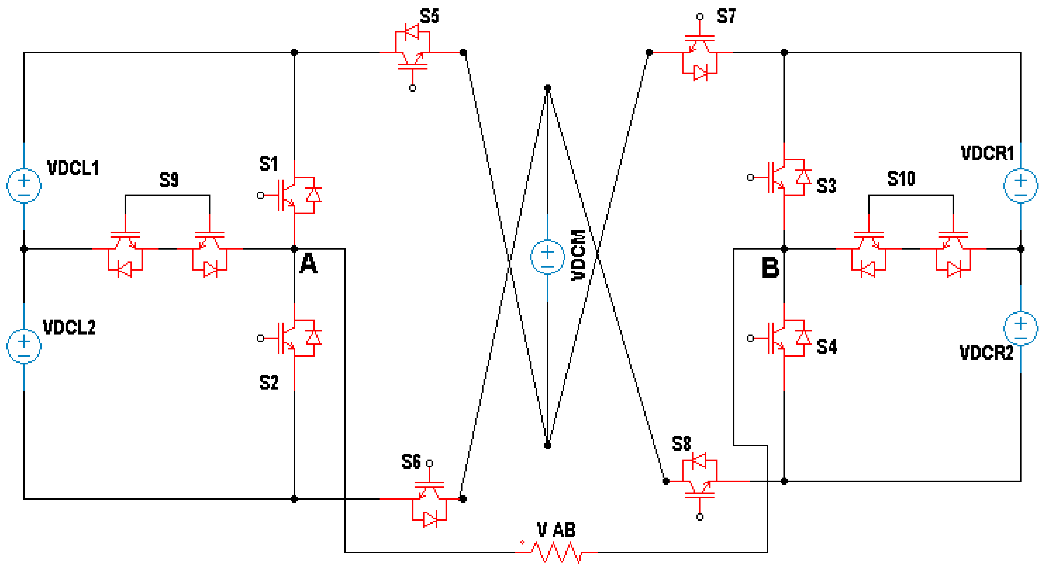
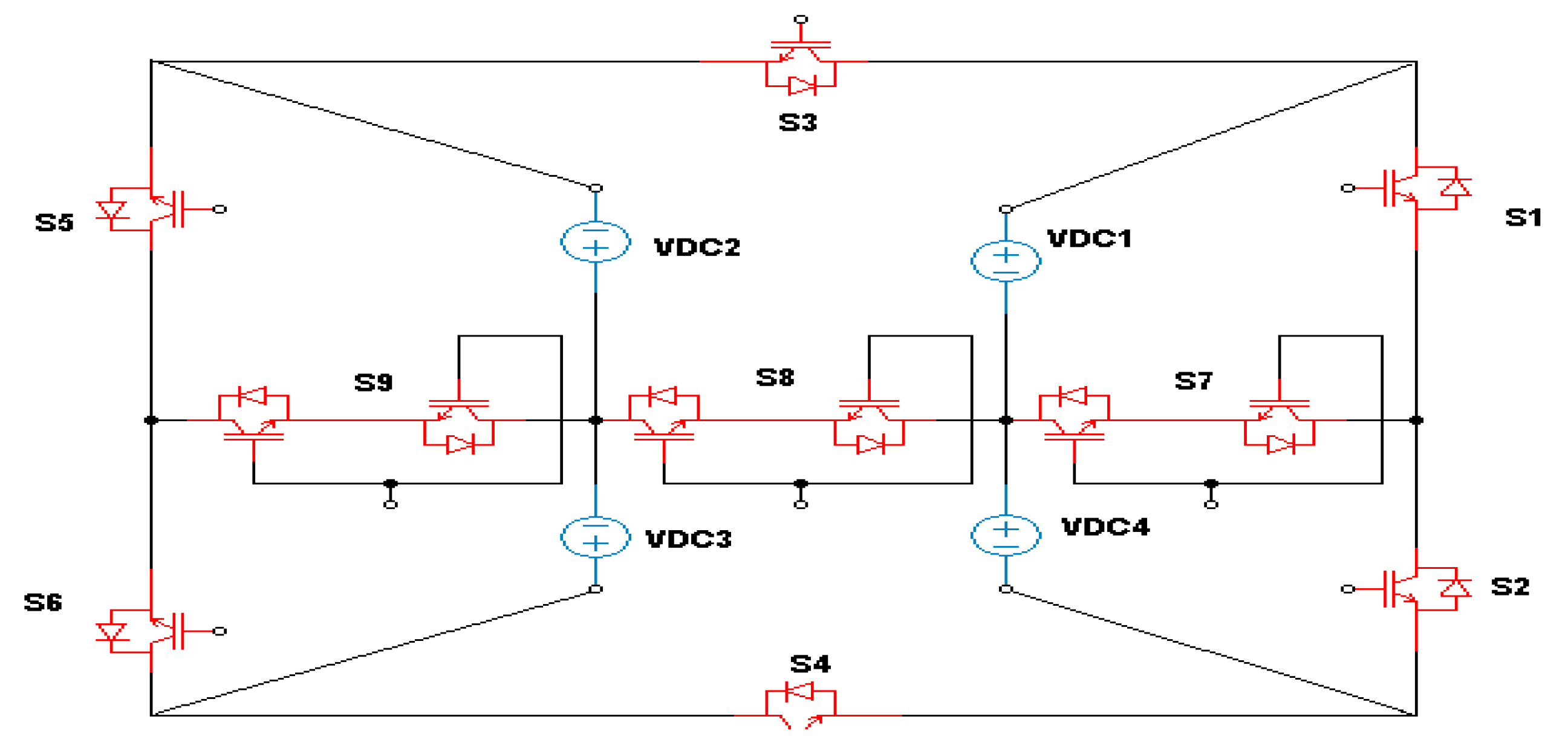
3.2. Complex Designs

Normally, the complex designs of T-MLIs are accompanied with an increase in the number of levels of the MLI output voltage to more than seven. Generally, most of the simple topologies of Section 3.1 can be maximized as nine-level inverters or even more levels [44]. A nine-level inverter is proposed in [45] and shown in Figure 10. It is based on the cascading modules of a T-type switched capacitor. The switched capacitors are enabled by a step-by-step charging method to attain voltage gain and high levels of output voltage. Furthermore, the inversion process is achieved without using an HB portion, which greatly decreases the number of switches. The proposed topology of this nine-level inverter can be constructed using only ten switches. Voltage gain is increased by two times. The nine levels of the output voltage are arranged as ( + 2   V dc , + 1.5   V dc   , +   V dc   , + 0.5   V dc ,   0   V dc , 0.5   V dc ,   V dc , 1.5   V dc     and 2   V dc ) .
A basic segment is formed by a back-to-back (BTB) connection with a modified T-shaped and half-bridge inverter (BBTHB), as shown in Figure 11a [46]. The HB portion of an inverter is linked to points A and B, which are shown in Figure 11b. There are five DC power sources at different voltage levels. The concept of this topology is to fabricate a new MLI structure with more output voltage levels but utilizing fewer switching devices. The proposed power circuit of the BBTHB module is shown in Figure 11c. This inverter topology can generate up to 31 voltage levels with five DC power sources using 12 power switches. It can provide negative levels without involving an HB. Table 1 illustrates the possible ON and OFF states of this T-type inverter. This topology exhibits in both the negative and positive voltage levels through switches   S 1 , S 1 _ 1   , S 2 and S 2 _ 2 . Simply, the voltage drop at the switches is due to a conduction process. Unidirectional switches S 1   ,   S 1 _ 1   S 2 ,   S 2 _ 2 ,   S 3 ,   S 3 _ 3 ,   S 4 ,   S 4 _ 4 ,   T 1 ,   T 1 _ 1 ,   T 2 , and are activated in the reverse modes to avoid shorting the DC power supply.
The topology proposed by [47] introduces a hybrid T-Type (HT) type MLI. This topology consists of 12 diodes and switching devices and five DC power sources. Eleven voltage levels can be generated by this MLI, which are (one zero-level, five negative-levels, and five positive-levels) in a symmetric configuration with no HB module.
The concept of this topology utilizes different sides of the DC power sources to create different routes that are coupled with the other DC sources, as shown in Figure 12. The switch set ( S 5 ,   S 6 ,   S 7 ,   and   S 8 ) is coupled with the (VC3M) DC source. Nearby switches ( S 1 S 4 ,   S 9 ,   and   S 10 ) work together for different levels of voltage generation. S9 and S10 are bidirectional switches mounted in both T-type modules at each side to prevent short-circuiting between the four DC sources (VDC1L, VDC2L, VDC1R, and VDC2R).
In [48], there is an MLI that shows some structural similarity to the proposed topology in [47], but using three modules. T-type modules are located at each end of the topology, denoted as T and T’. Switching devices, Sti and Sti’ where (i = 1...5), are utilized in these modules. Other modules, or switching devices, are positioned between the T-type configurations using interconnecting structures for scalable topologies. To step up the MLI AC voltage N times, several DC sources are required, [(N/2) − 1], with a cross module for each module and two capacitors.
The work of [49] presents a new and different module for asymmetric MLI inverters with fewer elements. This involves a square arrangement of two BTB T-MLIs with other switching devices. A square T-type (ST-type) portion creates seventeen levels using twelve switching devices and four different DC supplies having two voltage levels (three VDC and one VDC). The two strategies can also be expanded in a cascading arrangement to achieve even more levels. ST-type modules can be formed by connecting two T-connectors BTB from points A, B, and C. This means one bidirectional switch from point B, and two unidirectional switching devices should be added from points C and A, as shown in Figure 13. The intermediate circuits are assumed to have respective voltages of one VDC and three VDC for the first and second T-connections. This design is used for an MLI (with different ratios of intermediate circuits) to produce various numbers of output voltage levels and fewer switching devices.
Table 2 represents a comparison among the different T-Type MLIs that are discussed. A comparison is made between the number of switching devices for each MLI topology, the number of DC sources, the number of DC-link capacitors, the availability of switching modules, and blocking diodes. Some of the topologies can be extended for a higher number of levels (N) as in [31,32,34,36,41], but others are intended for the proposed number of levels [43,44,45,46,47,49]. Also, most of them have to balance the voltage across DC capacitors connected with a single DC source. In the rest of the topologies, DC capacitors are replaced by several DC sources. Few of them have switching modules, which are a combination of two opposite switching devices triggered by a single pulse at the same time. Each switch is an IGBT connected with an anti-parallel diode. Blocking diodes are also employed in most of the topologies to control the current path for the required instantaneous voltage level. The efficient inverter topology is that which has a low number of components and provides a possibly high number of levels for its output voltage. The selection of the efficient inverter topology is tied to that which has a low number of components and provides a possibly high number of levels for its output voltage.

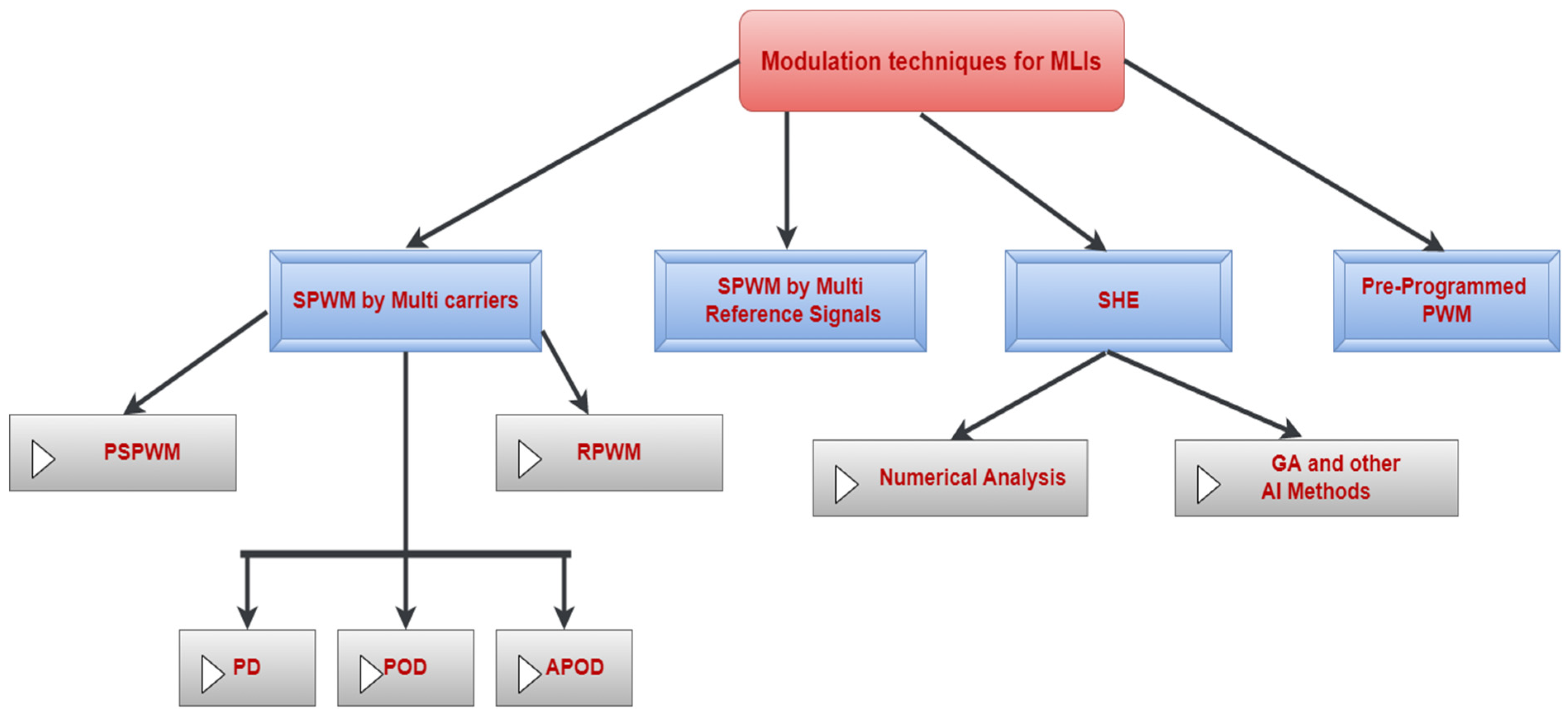
4. Modulation Techniques

The essential aim of a modulation technique is to provide synchronized pulses for each switching device of an MLI [50]. Also, they are used to decrease the harmonic content of the output current and voltage waveforms. Normally, the application of modulation techniques is made to every class of MLIs, not only T-MLIs. Figure 14 presents the modulation techniques that most researchers and manufacturers have followed in their MLI designs for many years [51,52,53,54].

4.1. SPWM by Multi-Carriers

Sinusoidal PWM or SPWM is the modulation technique most used for single- and three-phase inverters. SPWM can be used for MLIs in many ways. In this section, the SPWM is used based on a comparison among several saw-tooth or triangular carriers at high frequency and one sine wave as a reference (modulating) signal at a fundamental frequency. Normally, for a three-level MLI, two carriers are required. For a five-level inverter, four carriers are needed, and for a seven-level inverter, six carriers are required, i.e., for an N-level inverter, N−1 carriers are required [55,56]. Then the number of carriers can be reduced to N 1 2 if a sine wave reference signal is replaced by its absolute function, i.e., a reference signal of |sin(x)|. SPWM by multiple carriers can be classified as follows.

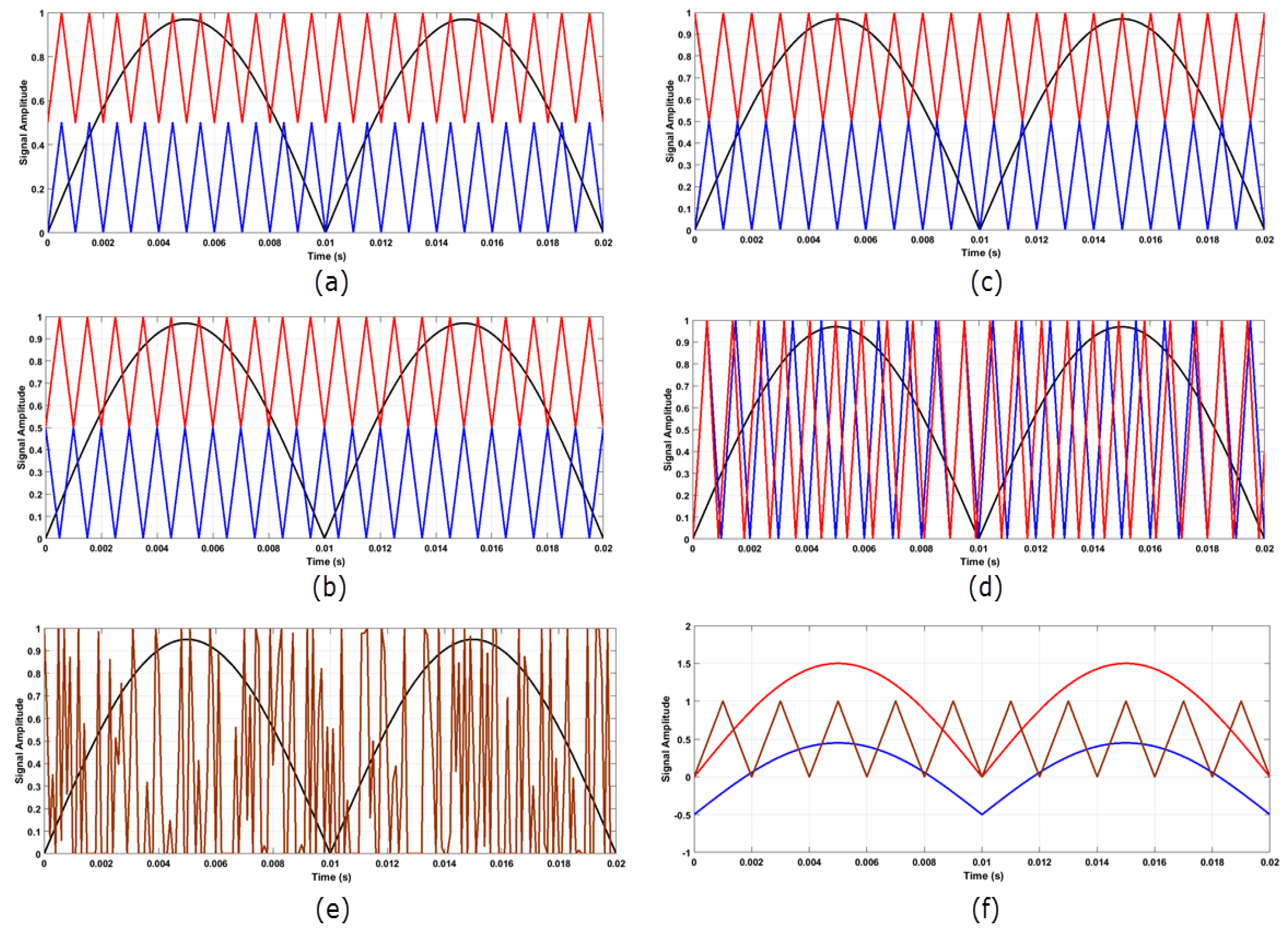
4.1.1. PD, POD, and APOD

In the phase disposition (PD) technique, all the triangular waveform carriers have the same phase, frequency, and waveform amplitude but they are set at different locations, as shown in Figure 15a. The major harmonic contents are induced at the carrier frequency [57,58]. In this method, only odd harmonics result [10]. Modulation in the PD technique can be used for an MLI with asymmetric topology as well [59,60]. In the phase opposition disposition (POD) technique, all the triangular waveform carriers are out of phase by (180°). The frequency and waveform amplitude are the same for all carriers, but they are at different locations, as shown in Figure 15b [61]. In the alternative phase opposition disposition (APOD) technique, the carrier’s waveform is alternatively displaced in phase by 180°, as shown in Figure 15c.

4.1.2. PSPWM

The phase-shifted (PSPWM) is an SPWM technique that uses multicarrier modulation. In this technique, each triangular carrier waveform has the same peak amplitude and frequency, but between any two adjacent carrier waves, there is a phase shift given by Φcr = 360 N 1 where N is the voltage level of an MLI [62,63,64]. For a five-level inverter, there is a phase displacement of 90° for any two adjacent carriers since four triangular carriers are required, as shown in Figure 15d.

4.1.3. RPWM

Random pulse width modulation (RPWM) is an SPWM technique that has become an essential tool for the mitigation of the harmonic effects of PWM inverters. This is a major improvement in the electromagnetic and acoustic noise from the output of RPWM inverters [65,66,67,68]. In this technique, a random number is compared with the sine wave signal or its absolute function, as shown in Figure 15e.

4.2. SPWM by Multi Reference Signals

In this modulation technique, there are only one or two triangular carrier waveforms and multi-reference signals that have the same frequency and phase, but their position is displaced. For a five-level inverter, there are two required sine wave references. For N-levels of the output voltage, N 1 2 sine wave reference signals are required, as shown in Figure 15f [69,70].

4.3. Selective Harmonics Elimination (SHE)

The PWM by SHE technique is made using a selective harmonic suppression scheme that relies on voltage waveforms in Fourier analysis. SHE determines an interval of the switching process that filters out unwanted output voltage harmonics and at the same time leaves the switching frequency unchanged.
For N-level MLIs, the mathematical expression of the eliminated harmonics is   N 3 2 For instance, to control a seven-level cascaded HB to reject the 5th and 7th harmonics, set the output phase voltages of each harmonic order to zero. A typical odd harmonic component and output phase voltage are expressed mathematically by Equations (1) and (2), respectively, and the odd harmonics and switching angles are as follows [71]:
For general output voltage,
V ( ω t ) = n = 1 , 3 , 5 , V n sin ( n ω t )
The odd harmonic components,
V n = 4   V d c n   π   i = 1 n cos ( n   ϑ i )  
For a seven-level inverter, the PWM by conventional SHE includes three switching angles. So, the nonlinear mathematical expressions are as follows:
{ c o s   α 1 + c o s   α 2 + c o s   α 3 3   π 4   M = 0 c o s   5   α 1 + c o s 5   α 2 + c o s   5   α 3 = 0 c o s   7   α 1 + c o s 7   α 2 + c o s   7   α 3 = 0  
Also, the condition that the switching angles must fulfill is as follows:
0 < α 1 < α 2 < α 3 < π 2
The optimal solutions of Equation (3) are found by taking into the consideration the constraints of Equation (4) through minimization of the objective function   F 1 as follows:
  F 1 = V 5 2 + V 7 2 V 1
where   α 1 , , α 3 are the switching angles,   V 1 ,   V 5 , and V 7 represent the fundamental component, fifth component, and seventh component of the output voltage, respectively.
In comparison with the other modulation schemes, the use of SHEPWM technology in MLIs provides a higher-quality output voltage. In the output voltage waveform, tight control and a high output harmonic voltage are achieved while keeping the frequency of switching devices at a minimum. The projected drawback of SHE is the high amplitude of the first set of unwanted harmonics [72,73,74,75]. The usage of numerical analysis for SHE for MLIs with a high number of levels is inefficient [76,77,78]. Optimization techniques using artificial intelligence (AI) techniques have been used directly to solve these problems. The primary reason for using these algorithms is that they do not have long ranges and do not rely on any initial assumptions. Thus, they can reduce computational effort. Moreover, these optimization techniques easily work on low-cost DSPs. Some of the bioinspired algorithms include the genetic algorithm (GA), bee algorithm (BA), particle swarm optimization (PSO), and differential evolution (DE), among other techniques [79]. Nonlinearities in low-order harmonic equations can originate using objective functions. Typically, researchers utilize various objective functions to reduce harmonics. Various methods have been proposed to solve harmonic suppression problems [80,81].

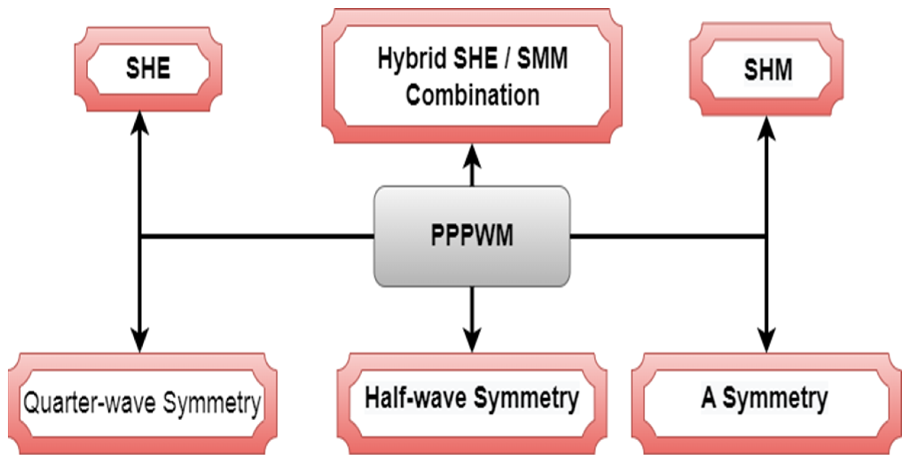
4.4. Pre-Programmed PPPWM

The PPPWM formulation usually depends on certain waveform characteristics, such as unipolar, bipolar, step, multistep, symmetric, and asymmetric waveforms [82,83,84,85,86,87]. All of these properties play the same significant role in analyzing and determining the shape and difficulty of a specific solution space. Figure 16 illustrates the common classification of PPPWM-type solutions. The SHE technique can be framed as a minimization function that seeks to eliminate the selected harmonics. The problem of selective harmonics mitigation (SHM) is often expressed as a minimization function that attempts to discover a global or local minimum rather than eliminating selected harmonics. It is sometimes formulated as a minimization function that provides a solution to create harmonic values and voltage/current so that the total harmonic distortion (THD) is below the limits of the applicable grid code [88,89,90,91,92,93,94].

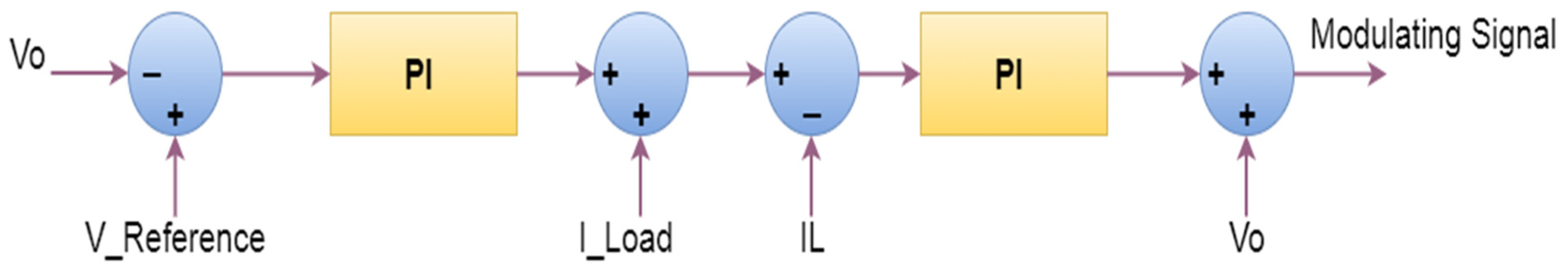
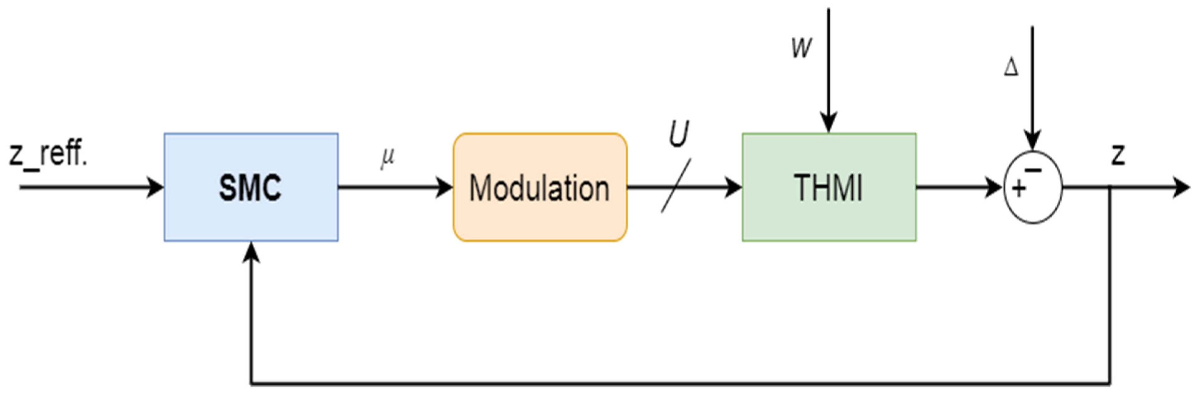
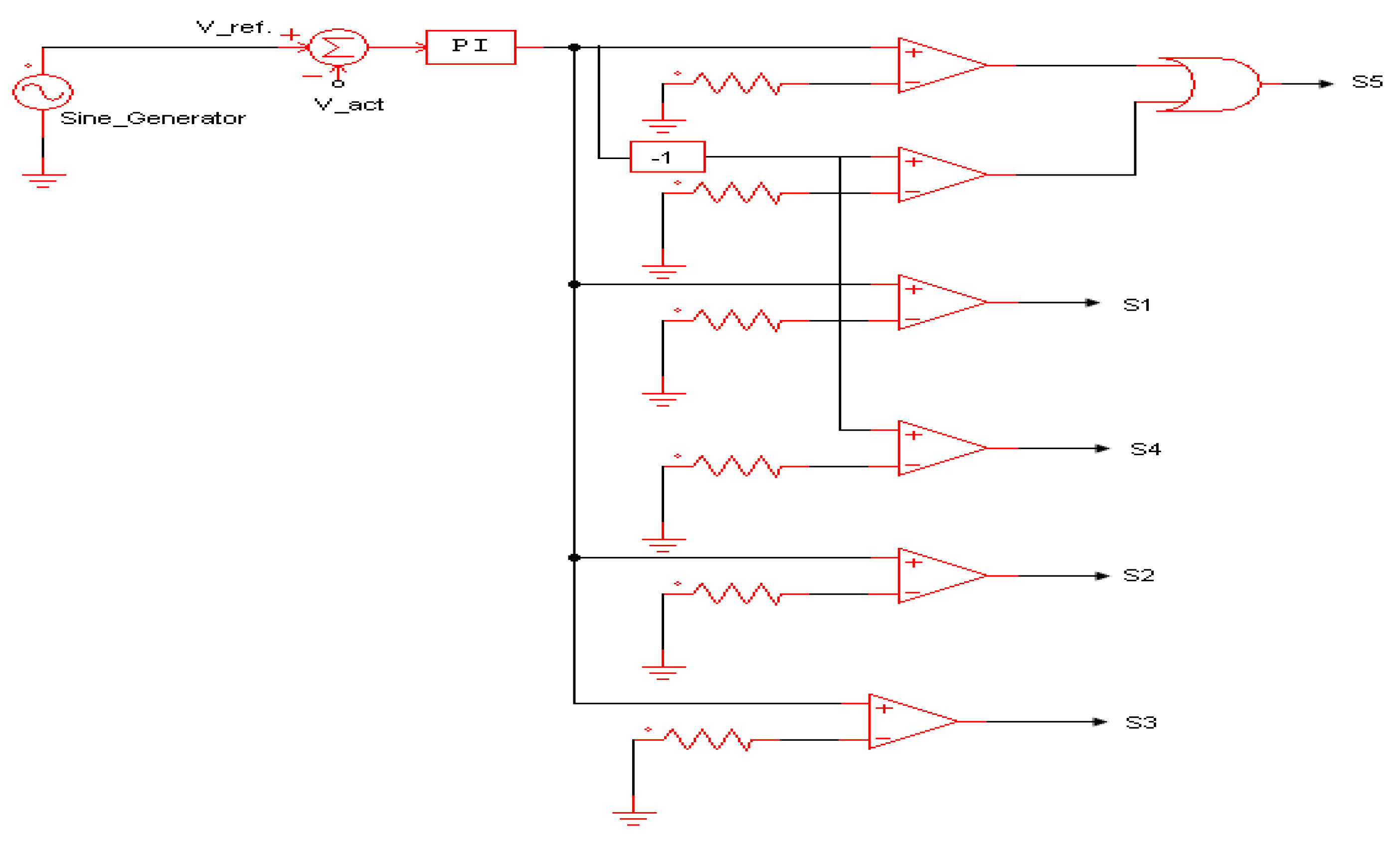
5. Output Voltage Control

The role of any modulation technique is to form the shape of the inverter output voltage so that it is as nearly a sinusoidal waveform as possible. However, these techniques and control methods can be merged to regulate the MLI output voltage. For MLIs, it is required that their output voltages have a constant root mean square (RMS) value at any load condition.
In most cases where an MLI is connected to a RES, during the normal operation of a wind turbine or PV system, the RES is variable in nature. Thus, maximum power point tracking (MPPT) methods [95,96,97] are employed to extract the maximum power from a RES, as depicted in Figure 17.
To reach the maximum power point (MPP) during changes in weather conditions, the V d c   of the MLIs is not fixed at a single value. To overcome this issue, voltage control methods are employed to regulate the MLI output voltage and achieve a constant-rated RMS voltage [98]. The common type of voltage control is performed using a proportional-integral (PI) controller. The value of the PI controller output (t) is fed to a boost converter circuit, and an error signal, e ( t ) is employed as follows [99]:
e ( t ) = S P P V
u ( t ) = e ( t ) × K P + K I T I   ʃ   e ( t ) d t            
where PV and   S P are the process variable and set point, respectively. u ( t ) represents the controlling signal which is resulted from the operation of the PI controller.   K P represents the proportional gain, K P is the integral gain, and T I represents the integration time constant. As shown in Figure 18, control of the output voltage (Vo) is performed by the feedback of Vo, load current (I_load), and inverter current (IL). A reference voltage signal is set and compared to Vo [100]. The error produced from the comparison is sent to the first PI controller. This PI controller is tuned, and its gain is set. Then, it sends a conditioned signal and adds it to the I_load. The collected signal is compared with the IL to produce the output current error. This error is sent to a second PI controller. The produced control signal is added with the Vo feedback signal to produce the main modulated signal.
Another method of controlling the Vo of an MLI is a sliding mode control (SMC). This was first presented in the 1950s by Russian engineers. It is a nonlinear controller primarily designed for the control of systems with variable geometry [101]. Its switching system time-dependent equation is as follows:
x ˙ ( t ) = g ( x ( t ) ) + φ ( x ( t ) ) × u ( t )
where x ( t ) is a state variable, u ( t ) is the controller input variable, g ( x ( t ) ) and φ ( x ( t ) ) are smooth vector fields in the same space [102]. In the case of a state-space environment, SMC can slide state variables of the system on a particular sliding surface. There are many kinds of slide mode controllers such as first order, second order, integral, and super-twisting, among others [101]. In the case of a first order SMC, the sliding surface is identified as follows:
σ = x 1 + c   x ˙ 1  
where σ is a as sliding variable, x 1 and x 2 are state variables, and c is a constant, where c > 1.
In a first order SMC, the controlling variable (u) is determined as follows:
u = ρ   s i g n ( σ )  
where
s i g n ( x ) = { 1   i f   x > 0 1   i f   x < 0
In a second order SMC, the sliding variable ( σ ) is calculated via the following formula:
σ = x ˙ 1 + c   | x 1 |   1 2   s i g n   ( x 1 )  
There is a new curved sliding surface for single-phase UPS. This rotary sliding-mode controller is a combination of a traditional SMC and fuzzy logic controllers. The main advantages of the proposed technique are lower THD and better dynamic response of inverter output voltage and current compared to a conventional SMC [102]. A variant of SMC of a trinary hybrid MLI was implemented [103,104]. Figure 19 is a diagram of a trinary hybrid MLI. A dynamic performance investigation was performed in which the MLI output current almost instantly reached the reference current. In a second test, input voltages from 130 V to 170 V were used. The output current did not vary from the reference current, but the voltage changed occasionally. The results of this SMC are compared with those of a PI controller. SMC has a significantly lower relative error, better SMC tuning response, and a larger perturbation clearance than a PI controller.
Another voltage control method was presented [105] for a five-level inverter. The stand-alone control scheme is separated into the following two parts: a power circuit and a control circuit. The former circuit consists of five power switches (S1-S5) and a power switch (D1) acting as a diode. The modulation technique is SPWM for power switching in the control circuit. A control circuit utilizes a reference sinusoidal signal and the actual signal from a voltage sensor. A reference signal is subtracted from the actual signal to generate an error signal. The error signal is input to a PI controller to generate a PI signal. Multiplying the PI signal by −1 produces a minimum signal shifted by 180°. The reference PI and minimum signals are modulated using a carrier signal employing a comparator circuit in a control circuit that generates an SPWM signal for each power switch. A schematic of the power supply and control is shown in Figure 20.
AI methods are used to control the voltage of an MLI either with the integration of multiple control methods or individually, such as a fuzzy logic controller (FLC), interval type 2 FLC (IT2FLC), neural networks, PSO, or GA, among others [106,107,108,109,110,111,112].

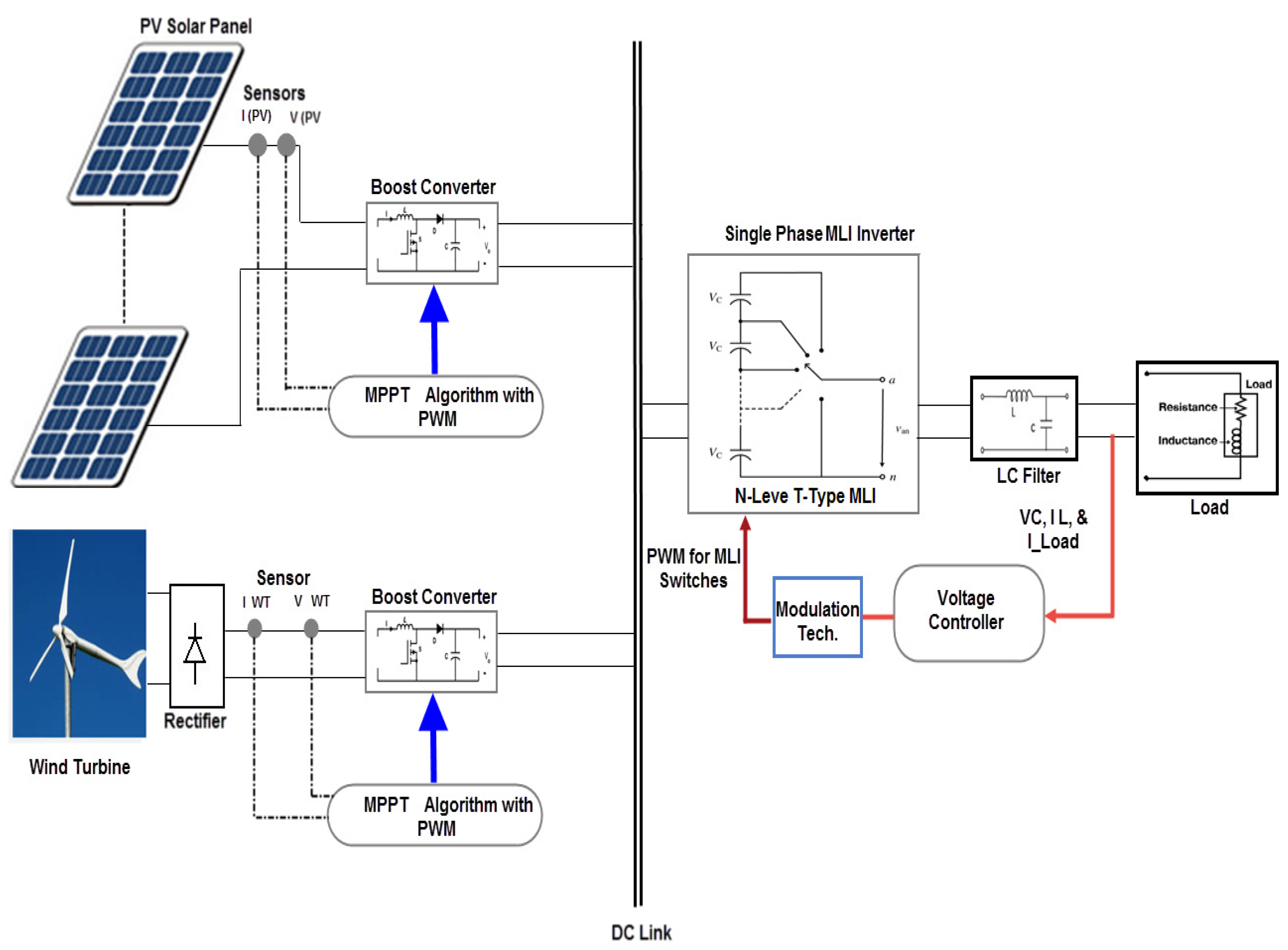
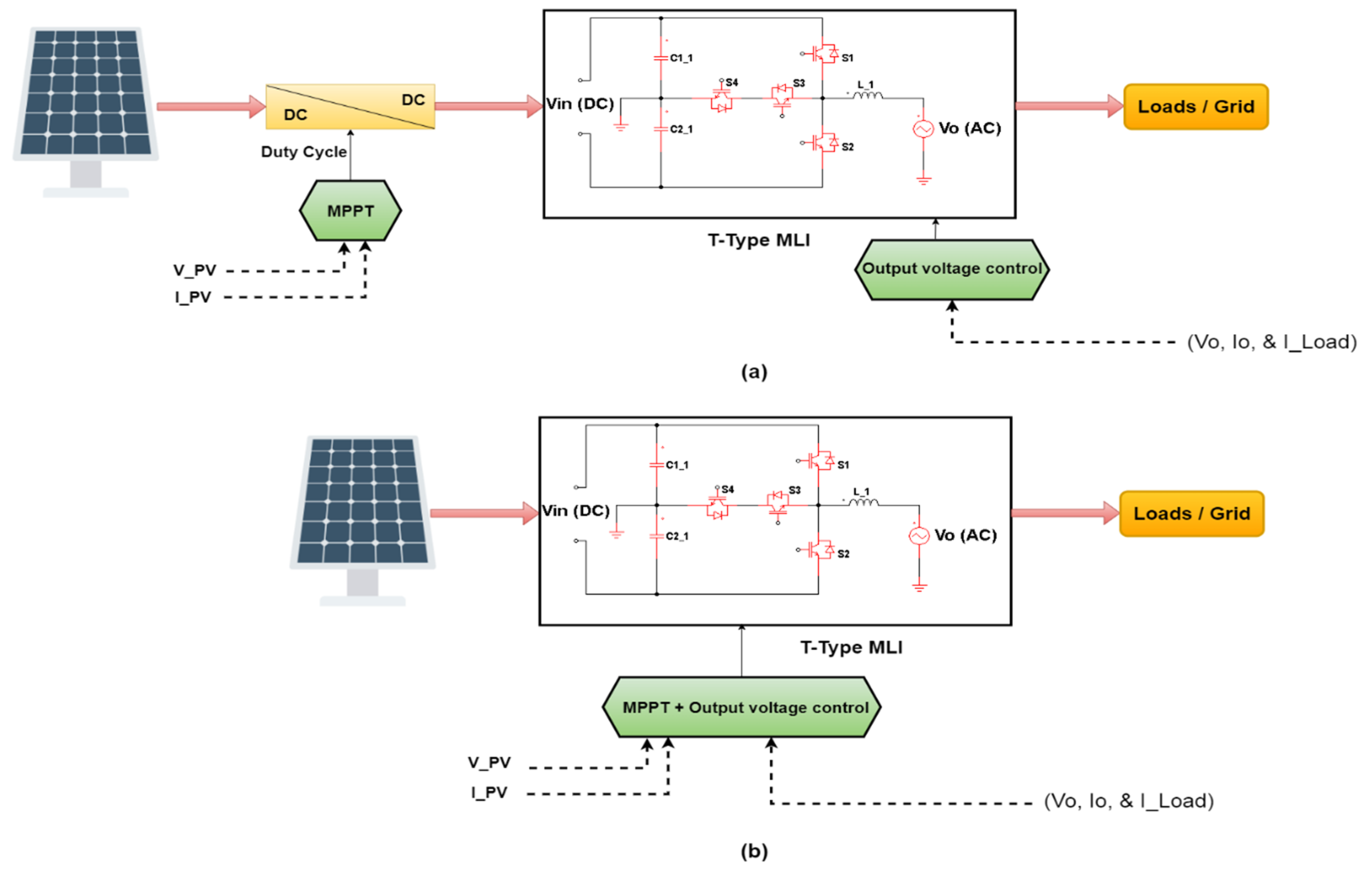
6. Connecting T-MLIs to RES

As discussed above, the RES may be wind or solar energy, where electrical energy can be extracted by wind turbines or PV panels, respectively. Recently, the use of thermoelectric generators (TEG) in conjunction with solar PV panels has attracted interest in using infrared waves in the solar spectrum that are converted to heat in solar panels. They convert this heat into electricity by the Seebeck effect. TEG modules can operate autonomously or be integrated with solar panels, which leads to an increased system efficiency and reduced environmental impact [113,114,115]. The T-MLIs can be connected to RES to either supply loads or grids with AC voltage. In both cases, an MPPT method should be employed due to the intermittent nature of RES. There are the following two kinds of MPPT implementation: either by adding a DC/DC converter such as a boot, buck, or SEPIC converter, among others [116,117,118,119,120], or directly using an inverter, as shown in Figure 21. If DC/DC converters are involved, then the role of the inverter is to provide a constant AC voltage to loads or a grid. In this way, control of the inverter voltage is simple. However, if they are not involved, it is crucial to perform MPPT as well to control the inverter output voltage, and the control technique will be more complex [121,122,123,124,125].

7. Output Voltage Filter Design

It is well established that the output voltage of MLIs has a staircase shape that is not a sinusoidal waveform. The role of an output voltage filter is to smooth the stairs and to produce a sinusoidal or semi-sinusoidal waveform. There are many kinds of passive filters that perform this function, such as LC, LCL, PI, or LLCL, among others. Their purpose is to reduce the THD % from the output voltage [126,127]. There are many ways to design filters. The design itself depends on the selection of the filter type, the modulation process, and the number of output voltage levels [128,129,130]. For the LC filter design, an inductor L is used to filter current harmonics, and a capacitor C is used to filter voltage harmonics. For L and C calculation purposes, the peak output voltage value is selected depending on the number of levels appropriate for the DC source voltage [128]. The cutoff frequency f c should be 10% of the switching frequency f s where:
f c = 10 %   f s
L = 0.03   V d c 2 π f c   I L   m a x
C = 1 ( 2 π f c ) 2 L
Before practical implementation, the design should be checked using a simulation software package to determine if slight modifications are required.

8. Challenges of Using T-MLIs

There are the following several challenges when using T-MLIs:
  • The main challenge of using T-MLI is in selecting their voltage-balancing capacitors on the DC link side. With an increasing number of output voltage levels, it is difficult to have the same voltage for all capacitors. In the case of unbalanced voltage levels of DC link capacitors, the output voltages will not be similar at all levels, which may lead to increased harmonics;
  • DC link capacitors should be of the type that is charged on both sides since the current can flow in either direction by changing the voltage from a positive value to one that is negative. Using unidirectional charging of capacitors or DC capacitors should be avoided since negative charging may overheat the capacitors and cause them to explode;
  • Selecting a proper voltage controller to regulate output voltage is important since, in most cases, these MLIs are supplied from a RES through DC/DC converters employing MPPT methods. Due to the variable nature of RES voltage, the DC link voltage should be sufficiently high, i.e., more than 1.5 times the rated DC link value. If the inverter provides 220 V AC, its DC link voltage is 311 V so, the DC link voltage should be 1.5 times this value. This is to allow flexible voltage control to regulate the output voltage level;
  • To increase the efficiency of a T-MLI, fewer switching devices should be used, which reflects the proper design topology of an MLI. Also, each switching device must be selected for low d v d t   and d i d t   properties;
  • The reliability of power converters is highly dependent on the reliable operation of semiconductor components. For each MLI topology, the switching device voltage and current stresses should be tested and analyzed during switching transients under different load conditions. Peak device current, peak device voltage, peak rate of change of device current   d i d t   , and peak rate of change of device voltage d v d t during turn-on and turn-off transients are measured over a wide range of operating conditions. To reduce the heavy d i d t     a n d   d v   d t   , it is helpful to design a damping circuit suitable for this purpose;
  • Since these MLIs are practically implemented to reduce their size, microcontrollers can be inserted into their circuitry to perform modulation techniques and regulate output voltage without depending on ICs and sub-circuits that could, in turn, increase losses and hence increase device temperature, as well as increase its size. For higher numbers of levels and at high switching frequencies, the MLIs will suffer from several thermal issues due to switching losses. Also, during normal operation, MLIs are subject to many variations in electrical loadings, which, through the Joule effect, create cyclic thermal stresses within the assembly. Thermally induced failure modes are the main causes of power inverter reliability issues. Due to the fact that the module contains a stack of various materials, cyclic thermal variations may drive mechanical strains, which are reduced by the mechanical cohesion of the assembly. Through the aging of the switching modules, these thermal effects may cause failure to it. The analysis of the thermal cycling frequency for the IGBT switching modules of the specific MLI topology can extend the time to failure by providing adequate cooling to the IGBT power modules [131,132,133]. Thus, the design of a good cooling and ventilation system is required where thermal cycling and ripples of temperature in low-frequency applications should be taken into consideration in the practical implementation of T-type MLIs.

9. Conclusions

A comprehensive survey of T-MLI topologies, modulation techniques, and their output voltage methods is presented. The aim of the present paper is to explore and compare the topologies of various simple and complex designs. For such MLIs, the selection of topology should be according to the system voltage (low or medium), types of loads, and whether the system is stand-alone or connected to the grid, as well as design complexity, as these impact physical size and cost. It is important to address the problems that face T-MLI for voltage balancing at DC link capacitors, the nature of the RES employed, the number of required levels, output voltage filtering requirements, PWM switching frequency, modulation techniques, and output voltage control method. From all the topologies, it can be concluded that T-MLIs with five or seven levels can be used for low-power applications, while nine levels and more can be used for higher-power applications. Under these scenarios, the MLI power losses will be low compared with the output loading power, which in turn increases its efficiency. The selection of a modulation technique is related to the design topology. Researchers must examine a variety of modulation techniques and compare them to determine which have low THD values.

Author Contributions

Conceptualization, M.F.M. and M.A.Q.; methodology, M.A.Q.; software, M.F.M.; validation M.F.M. and M.A.Q.; formal analysis, M.F.M.; investigation, M.A.Q.; resources, M.A.Q.; data curation, M.F.M.; writing—original draft preparation, M.F.M.; writing—review and editing, M.A.Q.; visualization, M.F.M.; supervision, M.A.Q.; project administration, M.F.M.; funding acquisition, M.A.Q. All authors have read and agreed to the published version of the manuscript.

Funding

Funding from the Ministry of Science and Higher Education of the Russian Federation (Ural Federal University Program of Development within the Priority-2030 Program) is gratefully acknowledged: Grant Number FEUZ-2022-0031.

Conflicts of Interest

The authors declare no conflict of interest.

References

  1. Thakre, K.; Mohanty, K.B.; Kommukuri, V.S.; Chatterjee, A.; Nigam, P.; Gupta, S.K. Modified cascaded multilevel inverter for renewable energy systems with less number of unidirectional switches. Energy Rep. 2022, 8, 5296–5304. [Google Scholar] [CrossRef]
  2. Obrecht, M.; Denac, M. Technologyforecast of sustainable energy development prospects. Futures 2016, 84, 12–22. [Google Scholar] [CrossRef]
  3. Emrani, A.; Berrada, A.; Arechkik, A.; Bakhouya, M. Improved techno-economic optimization of an off-grid hybrid solar/wind/gravity energy storage system based on performance indicators. J. Energy Storage 2022, 49, 104163. [Google Scholar] [CrossRef]
  4. Abu-Rub, H.; Malinowski, M.; Al-Haddad, K. Power Electronics for Renewable Energy Systems, Transportation and Industrial Applications; John Wiley & Sons Ltd.: Hoboken, NJ, USA, 2014. [Google Scholar]
  5. Suntio, T.; Messo, T. Power Electronics in Renewable Energy Systems. Energies 2019, 12, 1852. [Google Scholar] [CrossRef] [Green Version]
  6. Ikonen, M.; Laakkonen, O.; Kettunen, M. Two-Level and Three-Level Converter Comparison. In Wind Power Application; Citeseer: Princeton, NJ, USA, 2005. [Google Scholar]
  7. Srinivasan, G.K.; Rivera, M.; Loganathan, V.; Ravikumar, D.; Mohan, B. Trends and Challenges in Multi-Level Inverter with Reduced Switches. Electronics 2021, 10, 368. [Google Scholar] [CrossRef]
  8. Qin, H.; Xie, S.; Xun, Q.; Zhang, F.; Xu, Z.; Wang, L. An optimized parameter design method of SiC/Si hybrid switch considering turn-off current spike. Energy Rep. 2022, 8 (Suppl. S13), 789–797. [Google Scholar] [CrossRef]
  9. Li, L.L.; Liu, Z.F.; Tseng, M.L.; Zhou, L.; Qi, F.D. Prediction of IGBT power module remaining lifetime using the aging state approach. Microelectron. Reliab. 2019, 102, 113476. [Google Scholar] [CrossRef]
  10. Khomfoi, S.; Tolbert, L.M. Chapter 13-Multilevel Power Converters. In Power Electronics Handbook, 4th ed.; Rashid, M.H., Ed.; Butterworth-Heinemann: Oxford, UK, 2018; pp. 385–416. [Google Scholar]
  11. Mali, R.; Adam, N.; Satpaise, A.; Vaidya, A.P. Performance Comparison of Two Level Inverter with Classical Multilevel Inverter Topologies. In Proceedings of the 2019 IEEE International Conference on Electrical, Computer and Communication Technologies (ICECCT), Coimbatore, India, 20–22 February 2019; pp. 1–7. [Google Scholar]
  12. Jaouad, N.C.; Chaikhy, H.; Belhora, F.; Hajjaji, A. Comparison between two levels and multi-level (NPC and Cascade) inverters. Mater. Today Proc. 2022, 66, 162–180. [Google Scholar] [CrossRef]
  13. Venkataramanaiah, J.; Suresh, Y.; Panda, A.K. A review on symmetric, asymmetric, hybrid and single DC sources based multilevel inverter topologies. Renew. Sustain. Energy Rev. 2017, 76, 788–812. [Google Scholar] [CrossRef]
  14. Dhanamjayulu, C.; Sanjeevikumar, P.; Muyeen, S.M. A structural overview on transformer and transformer-less multilevel inverters for renewable energy applications. Energy Rep. 2022, 8, 10299–10333. [Google Scholar] [CrossRef]
  15. Ngo, B.B.; Nguyen, M.K.; Kim, J.H.; Zare, F. Single-phase multilevel inverter based on switched-capacitor structure. IET Power Electron. 2018, 11, 1858–1865. [Google Scholar] [CrossRef]
  16. Vo, D.-V.; Nguyen, M.-K.; Do, D.-T.; Choi, Y.-O. A Single-Phase Nine-Level Boost Inverter. Energies 2019, 12, 394. [Google Scholar] [CrossRef] [Green Version]
  17. Mohammed, M.F.; Ahmad, A.H.; Humod, A.T. New Switching Technique for The Modified Cascade Five Levels Inverter. ARPN J. Eng. Appl. Sci. 2018, 13, 4346–4350. [Google Scholar]
  18. Han, D.; Peng, F.Z.; Dwari, S. Advanced PWM Techniques for Multi-level Inverters with a Multi-level Active CM Noise Filter. IEEE J. Emerg. Sel. Top. Power Electron. 2021. [Google Scholar] [CrossRef]
  19. Farias, F.; Abdulla, W. A method for selecting a proper modulation technique for the parametric acoustic array. IOP Conf. Ser. J. Phys. 2018, 1075, 012035. [Google Scholar] [CrossRef]
  20. António-Ferreira, A.; Collados-Rodríguez, C.; Gomis-Bellmunt, O. Modulation techniques applied to medium voltage modular multilevel converters for renewable energy integration: A review. Electr. Power Syst. Res. 2018, 155, 21–39. [Google Scholar] [CrossRef] [Green Version]
  21. Rashid, M.H. Power Electronics Circuits, Devices, and Applications, 3rd ed.; Pearson Education Inc.: New York, NY, USA, 2007; pp. 248–270. [Google Scholar]
  22. Bimbhra, P.S. Power Electronics, 4th ed.; Khanna Publishers: Bangalore, India, 2010; pp. 455–456. [Google Scholar]
  23. Schweizer, M.; Kolar, J.W. Design and Implementation of a Highly Efficient Three-Level TType Converter for Low-Voltage Applications. IEEE Trans. Power Electron. 2013, 28, 899–907. [Google Scholar] [CrossRef]
  24. “Three-Phase T-Type Inverter”, PLECS DEMO MODEL, Last updated in PLECS 4.6.1. Available online: https://www.plexim.com/sites/default/files/demo_models_categorized/plecs/three_phase_t_type_inverter.pdf (accessed on 15 September 2022).
  25. Zhou, L.; Gao, F.; Yang, T. Neutral-point-clamped circuits of single-phase PV inverters: Generalized principle and implementation. In Proceedings of the 2015 IEEE Energy Conversion Congress and Exposition (ECCE), Montreal, QC, Canada, 20–24 September 2015; pp. 442–449. [Google Scholar]
  26. Nabae, A.; Takahashi, I.; Akagi, H. A New Neutral-Point-Clamped PWM Inverter. IEEE Trans. Ind. Appl. 1981, IA-17, 518–523. [Google Scholar] [CrossRef]
  27. Faraji, F.; Hajirayat, A.; Birjandi, A.A.M.; Al-Haddad, K. Single-stage single-phase three-level neutral-point-clamped transformerless grid-connected photovoltaic inverters: Topology review. Renew. Sustain. Energy Rev. 2017, 80, 197–214. [Google Scholar] [CrossRef]
  28. Sinha, G.; Lipo, T.A. A new modulation strategy for improved DC bus utilization in hard and soft switched multilevel inverters. In Proceedings of the IECON’97 23rd International Conference on Industrial Electronics, Control, and Instrumentation (Cat. No.97CH36066), New Orleans, LA, USA, 14 November 1997; Volume 2, pp. 670–675. [Google Scholar] [CrossRef]
  29. Alepuz, S.; Busquets- Monge, S.; Nicolás-Apruzzese, J.; Filbà-Martínez, À.; Bordonau, J.; Yuan, X.; Kouro, S. A Survey on Capacitor Voltage Control in Neutral-Point-Clamped Multilevel Converters. Electronics 2022, 11, 527. [Google Scholar] [CrossRef]
  30. Gurpinar, E.; Castellazzi, A. Single-Phase T-Type Inverter Performance Benchmark Using Si IGBTs, SiC MOSFETs, and GaN HEMTs. IEEE Trans. Power Electron. 2016, 31, 7148–7160. [Google Scholar] [CrossRef]
  31. Zhang, Z.; Zhang, J.; Wu, X. A single phase T-type inverter operating in boundary conduction mode. In Proceedings of the 2016 IEEE Energy Conversion Congress and Exposition (ECCE), Milwaukee, WI, USA, 18–22 September 2016; pp. 1–6. [Google Scholar]
  32. Mohammed, M.F.; Ahmad, A.H.; Humod, A.T. Design and Simulation of a New Seven Levels Inverter for Renewable Energy Sources. J. Eng. Appl. Sci. 2018, 13, 6866–6872. [Google Scholar]
  33. Mohammed, M.F.; Ahmad, A.H.; Humod, A.T. Harmonics reduction of a five-level inverter by unbalanced carriers and over-modulation techniques. Int. J. Eng. Technol. 2018, 7, 1059–1063. [Google Scholar] [CrossRef]
  34. Yu, H.; Chen, B.; Yao, W.; Lu, Z. Hybrid Seven-Level Converter Based on T-Type Converter and H-Bridge Cascaded Under SPWM and SVM. IEEE Trans. Power Electron. 2018, 33, 689–702. [Google Scholar] [CrossRef]
  35. Jacob, J.T.; Kirubakaran, D. A Hybrid T-Type Multilevel Inverter with A Novel Modulation Strategy for Isolated Supply Electric Systems. J. Eng. Sci. Technol. 2019, 14, 1614–1638. [Google Scholar]
  36. Ceglia, G.; Guzman, V.; Sanchez, C.; Ibanez, F.; Walter, J.; Gimenez, M.I. A New Simplified Multilevel Inverter Topology for DC–AC Conversion. IEEE Trans. Power Electron. 2006, 21, 1311–1319. [Google Scholar] [CrossRef]
  37. Bhaskar, M.S.; Almakhles, D.; Padmanaban, S.; Ionel, D.M.; Blaabjerg, F.; He, J.; Kumar, A.R. Investigation of a Transistor Clamped T-Type Multilevel H-Bridge Inverter With Inverted Double Reference Single Carrier PWM Technique for Renewable Energy Applications. IEEE Access 2020, 8, 161787–161804. [Google Scholar] [CrossRef]
  38. Rahim, N.A.; Chaniago, K.C.; Selvarage, J. A modified H Bridge Multilevel Inverter for Photovoltaic System. IEICE Elecronic Express 2010, 7, 751–758. [Google Scholar] [CrossRef] [Green Version]
  39. Sudheer, D.S.; Reddy, S.; Kumar, J.S.; Ayyapparaju, C.B.; Reddy, M.S. A Single-Phase Inverter Topology with Seven-Level Output based on T-type Structure. In Proceedings of the 2021 6th International Conference for Convergence in Technology (I2CT), Maharashtra, India, 2–4 April 2021; pp. 1–4. [Google Scholar]
  40. Mustafa, I.N.C.I. Performance Analysis of T-type Inverter Based on Improved Hysteresis Current Controller. Balk. J. Electr. Comput. Eng. 2019, 7, 147–155. [Google Scholar]
  41. Karthik, K.I.N.; Srinivasa Rao, S. Five-Level Inverter Using POD PWM Technique. In Proceedings of the International Conference on Electrical, Electronics, Signals, Communication and Optimization (EESCO), Visakhapatnam, India, 24–25 January 2015; pp. 1–6. [Google Scholar]
  42. Sunddararaj, S.P.; Rangarajan, S.S.; Subashini, N.; Subramaniam, U.; Collins, E.R.; Senjyu, T. A novel T-Type Multilevel Inverter for Electric Vehicle and Grid-connected applications. In Proceedings of the 2021 7th International Conference on Electrical Energy Systems (ICEES), Chennai, India, 11–13 February 2021; pp. 166–170. [Google Scholar]
  43. Dhara, S.; Hota, A.; Jain, S.; Agarwal, V. A Novel Single-Phase T-Type PV Inverter with Improved DC Utilization. In Proceedings of the 2018 IEEE International Conference on Power Electronics, Drives and Energy Systems (PEDES), Chennai, India, 18–21 December 2018; pp. 1–5. [Google Scholar]
  44. Ouchatti, A.; Majdoul, R.; Moutabir, A.; Taouni, A.; Touati, A. Modified T-type topology of three-phase multi-level inverter for photovoltaic systems. Int. J. Electr. Comput. Eng. 2022, 12, 262–268. [Google Scholar] [CrossRef]
  45. Wang, Y.; Yuan, Y.; Li, G.; Chen, T.; Wang, K.; Liang, J. A Generalized Multilevel Inverter Based on T-Type Switched Capacitor Module with Reduced Devices. Energies 2020, 13, 4406. [Google Scholar] [CrossRef]
  46. Hosseinzadeh, M.A.; Sarbanzadeh, M.; Sarebanzadeh, E.; Rivera, M.; Munoz, J. Reduced modified T-type topology for cascaded multilevel inverters. In Proceedings of the 2018 IEEE International Conference on Automation/XXIII Congress of the Chilean Association of Automatic Control (ICA-ACCA), Concepcion, Chile, 17–19 October 2018; pp. 1–6. [Google Scholar]
  47. Meraj, S.T.; Yahaya, N.Z.; Hasan, K.; Masaoud, A. A hybrid T-type (HT-type) multilevel inverter with reduced components. Ain Shams Eng. J. 2021, 12, 1959–1971. [Google Scholar] [CrossRef]
  48. Khenar, M.; Taghvaie, A.; Adabi, J. Multi-level inverter with combined T-type and cross-connected modules. IET Power Electron. 2018, 11, 1407–1415. [Google Scholar] [CrossRef]
  49. Samadaei, E.; Sheikholeslami, A.; Gholamian, S.A.; Adabi, J. A Square T-Type (ST-Type) Module for Asymmetrical Multilevel Inverters. IEEE Trans. Power Electron. 2018, 33, 987–996. [Google Scholar] [CrossRef]
  50. Chandwani, H.B.; Matnani, M.K. A review of modulation techniques for hybrid multilevel inverter. In Proceedings of the 2012 1st International Conference on Emerging Technology Trends in Electronics, Communication & Networking, Surat, India, 19–21 December 2012; pp. 1–7. [Google Scholar]
  51. Balamurugan, C.R.; Natarajan, S.P.; Bensraj, R.; Shanthi, B. A Review on Modulation Strategies of Multi Level Inverter. Indones. J. Electr. Eng. Comput. Sci. 2016, 3, 681–705. [Google Scholar] [CrossRef]
  52. Hasan, N.S.; Rosmin, N.; Osman, D.A.A.; Musta’amal, A.H. Reviews on multilevel converter and modulation techniques. Enewable Sustain. Energy Rev. 2017, 80, 163–174. [Google Scholar] [CrossRef]
  53. Kumar, M.S.; Ramani, K. Comparative Review of Modulation Techniques for Harmonic Minimization in Multilevel Inverter. Int. J. Electr. Comput. Eng. 2014, 8, 1938–1945. [Google Scholar]
  54. Poorfakhraei, A.; Narimani, M.; Emadi, A. A Review of Modulation and Control Techniques for Multilevel Inverters in Traction Applications. IEEE Access 2021, 9, 24187–24204. [Google Scholar] [CrossRef]
  55. Rodriguez, J.; Lai, J.-S.; Peng, F.Z. Multilevel inverters: A survey of topologies, controls, and applications. IEEE Trans. Ind. Electron. 2002, 49, 724–738. [Google Scholar] [CrossRef] [Green Version]
  56. McGrath, B.P.; Holmes, D.G. Multicarrier PWM Strategies for Multilevel Inverters. IEEE Trans. Ind. Electron. 2002, 49, 858–867. [Google Scholar] [CrossRef]
  57. Rathore, S.; Kirar, M.K.; Bhardwaj, S.K. Simulation of cascaded h- bridge multilevel inverter using pd, pod, apod techniques. Electr. Comput. Eng. Int. J. 2015, 4, 27–41. [Google Scholar] [CrossRef]
  58. Suresh, S.R.K. Analysis of pd, pod, apod, co and vf pwm techniques for cascaded inverter. South Asian J. Eng. Technol. 2016, 2, 46–55. [Google Scholar]
  59. Aghdam, M.G.H.; Fathi, S.H.; Gharehpetian, G.B. Analysis of multi-carrier PWM methods for asymmetric multi-level inverter. In Proceedings of the 2008 3rd IEEE Conference on Industrial Electronics and Applications ICIEA, Singapore, 3–5 June 2008; pp. 2057–2062. [Google Scholar]
  60. İnci, M. Performance Evaluation of Multi-carrier PWM Techniques: PD, POD and APOD. Int. J. Appl. Math. Electron. Comput. 2019, 7, 38–43. [Google Scholar] [CrossRef]
  61. Kumar, K.V.; Thulasiram, I. Comparison Of APOD And POD Control Techniques For A Cascaded H-Bridge Multi Level Inverter. Int. J. Eng. Res. Technol. 2013, 2, 1–5. [Google Scholar]
  62. Venkatakrishna, A.; Somanatham, R.; Reddy, M.S. Phase Shifted and Level Shifted PWM Based Cascaded Multilevel Inverter Fed Induction Motor Drive. Int. J. Curr. Eng. Technol. 2014, 4, 350–354. [Google Scholar]
  63. Xiao, M.; Xu, Q.; Ouyang, H. An Improved Modulation Strategy Combining Phase Shifted PWM and Phase Disposition PWM for Cascaded H-Bridge Inverters. Energies 2017, 10, 1327. [Google Scholar] [CrossRef] [Green Version]
  64. Radan, A.; Shahirinia, A.H.; Falahi, M. Evaluation of carrier-based PWM methods for multi-level inverters. In Proceedings of the IEEE International Symposium on Industrial Electronics, Vigo, Spain, 4–7 June 2007; pp. 389–394. [Google Scholar]
  65. Cheng, Q.; Wang, C.; Wang, J. Analysis on Displacement Angle of Phase-Shifted Carrier PWM for Modular Multilevel Converter. Energies 2020, 13, 6743. [Google Scholar] [CrossRef]
  66. Mardaneh, M.; Hashemi, Z. A random switching method for PWM cascaded H-bridge multi-level inverter. In Proceedings of the 2012 IEEE International Conference on Circuits and Systems (ICCAS), Kuala Lumpur, Malaysia, 3–4 October 2012; pp. 76–79. [Google Scholar]
  67. George, D.S.; Shiny, G. Random pulsewidth modulation technique for a 4-level inverter. Int. J. Adv. Res. Eng. Technol. 2015, 6, 24–33. [Google Scholar]
  68. Jadeja, R.; Ved, A.; Chauhan, S. An Investigation on the Performance of Random PWM Controlled Converters. Eng. Technol. Appl. Sci. Res. 2015, 5, 876–884. [Google Scholar] [CrossRef]
  69. Rahim, N.A.; Selvaraj, J. A novel multi-string five-level PWM inverter for photovoltaic application. In Proceedings of the 2011 IEEE International Electric Machines & Drives Conference (IEMDC), Niagara Falls, ON, Canada, 15–18 May 2011; pp. 510–514. [Google Scholar]
  70. Vemuganti, H.P.; Sreenivasarao, D.; Kumar, G.S. Improved pulse-width modulation scheme for T-type multilevel inverter. IET Power Electron. 2017, 10, 968–976. [Google Scholar] [CrossRef]
  71. Fakhry, M.G.; Massoud, A.; Ahmed, S. Quasi seven-level operation of multilevel converters with selective harmonic elimination. In Proceedings of the 26th International Conference on Microelectronics (ICM), Doha, Qatar, 14–17 December 2014. [Google Scholar]
  72. Konstantinou, G.; Ciobotaru, M.; Agelidis, V. Selective harmonic elimination pulse width modulation of modular multilevel converters. IET Power Electron. 2013, 6, 96–107. [Google Scholar] [CrossRef]
  73. Guzman, J.I.; Melin, P.E.; Espinoza, J.R.; Moran, L.A.; Baier, C.R.; Munoz, J.A.; Guinez, G.A. Digital implementation of selective harmonic elimination techniques in modular current source rectifiers. IEEE Trans. Ind. Inform. 2013, 9, 1167–1177. [Google Scholar] [CrossRef]
  74. Gabour, N.E.H.; Boudissa, E.G.; Bounekhla, M.H. Optimal HSE-PWM based on genetic algorithm for seven levels diode clamped multilevel inverter. Period. Eng. Nat. Sci. 2020, 8, 859–869. [Google Scholar]
  75. Yang, K.; Yuan, Z.; Yuan, R.; Yu, W.; Yuan, J.; Wang, J. A Groebner Bases Theory-Based Method for Selective Harmonic Elimination. IEEE Trans. Power Electron. 2015, 30, 6581–6592. [Google Scholar] [CrossRef]
  76. Salas, V.; Olías, E. An analysis of the technical exigencies and CE marking relative to low voltage (less than 5 kW) photovoltaic inverters marketed in Spain. Renew. Sustain. Energy Rev. 2009, 13, 1635–1640. [Google Scholar] [CrossRef]
  77. Abdelaziz, E.A.; Saidur, R.; Mekhilef, S. A review on energy saving strategies in industrial sector. Renew. Sustain. Energy Rev. 2011, 15, 150–168. [Google Scholar] [CrossRef]
  78. Meral, M.E.; Diner, F. A review of the factors affecting operation and efficiency of photovoltaic based electricity generation systems. Renew. Sustain. Energy Rev. 2011, 15, 2176–2184. [Google Scholar] [CrossRef]
  79. Sallama, A.; Abbod, M.; Khan, S.M. Applying sequential particle swarm optimization algorithm to improve power generation quality. Int. J. Eng. Technol. Innov. 2014, 4, 223–233. [Google Scholar]
  80. Rasheed, M.; Omar, R.; Sulaiman, M.; Halim, W.A.; Majeda, M.M.A.A. Artificial Intelligence Technique to Real-Time Based on Selective Harmonic Elimination in Modified Multilevel Inverter. J. Eng. Appl. Sci. 2019, 14, 9692–9700. [Google Scholar] [CrossRef] [Green Version]
  81. Rasheed, M.; Alakkad, M.M.A.; Omar, R.; Sulaiman, M.; Halim, W.A. Enhance the accuracy of control algorithm for multilevel inverter based on artificial neural network. J. Electr. Eng. Comput. Sci. 2020, 20, 1148–1158. [Google Scholar] [CrossRef]
  82. Dahidah, M.S.A.; Konstantinou, G.; Agelidis, V.G. A review of multilevel selective harmonic elimination PWM: Formulations, solving algorithms, implementation and applications. IEEE Trans. Power Electron. 2015, 30, 4091–4106. [Google Scholar] [CrossRef]
  83. Konstantinou, G.; Agelidis, V.G. Bipolar Switching Waveform: Novel Solution Sets to the Selective Harmonic Elimination Problem. In Proceedings of the IEEE International Conference on Industrial Technology, Via del Mar, Chile, 14–17 March 2010. [Google Scholar]
  84. Agelidis, V.G.; Balouktsis, A.; Balouktsis, I. On applying a minimization technique to the harmonic elimination PWM control:The bipolar waveform. IEEE Trans. Power Electron. 2004, 2, 41–44. [Google Scholar]
  85. Konstantinou, G.; Agelidis, V.G. On re-examining symmetry of two-level selective harmonic elimination PWM: Novel formulations, solutions and performance evaluation. Electr. Power Syst. Res. 2014, 108, 185–197. [Google Scholar] [CrossRef]
  86. Agelidis, V.G.; Balouktsis, A.; Balouktsis, I.; Cossar, C. Multiple sets of solutions for harmonic elimination PWM bipolar waveforms: Analysis and experimental verification. IEEE Trans. Power Electron. 2006, 21, 415–421. [Google Scholar] [CrossRef] [Green Version]
  87. Dahidah, M.S.A.; Konstantinou, G.; Flourentzou, N.; Agelidis, V.G. On comparing the symmetrical and non-symmetrical selective harmonic elimination pulse-width modulation technique for two-level three-phase voltage source converters. IET Power Electron. 2010, 3, 829–842. [Google Scholar] [CrossRef]
  88. El-Bakry, M. Selective Harmonics Minimization for Multilevel Inverters. In Proceedings of the IEEE International Conference on Computer and Electrical Engineering, Dubai, United Arab Emirates, 28–30 December 2009. [Google Scholar]
  89. Sahali, Y.; Fellah, M.K. Application of the Optimal Minimization of The THD Technique to The Multilevel Symmetrical Inverters and Study of Its Performance in Comparison with the Selective Harmonic Elimination Technique. In Proceedings of the IEEE International Symposium on Power Electronics, Electrical Drives, Automation and Motion, Taormina, Italy, 23–26 May 2006. [Google Scholar]
  90. Naderi, Y.; Hosseini, S.H.; Mahari, A.; Naderi, R. A New Strategy for Harmonic Minimization Based on Triple Switching of Multilevel Converters. In Proceedings of the Iranian Conference on Electrical Engineering, Mashhad, Iran, 1–6 December 2013. [Google Scholar]
  91. Liu, Y.; Hong, H.; Huang, A.Q. Real-time calculation of switching angles minimizing THD for multilevel inverters with step modulation. IEEE Trans. Ind. Electron. 2009, 56, 285–293. [Google Scholar] [CrossRef]
  92. Liu, Y.; Hong, H.; Huang, A.Q. Real-time algorithm for minimizing THD in multilevel inverters with unequal or varying voltage steps under staircase modulation. IEEE Trans. Ind. Electron. 2009, 56, 2249–2258. [Google Scholar] [CrossRef]
  93. Ahmad, S.; Khan, I.; Iqbal, A.; Rahman, S. A Novel Pulse Width Amplitude Modulation for Elimination of Multiple Harmonics In Asymmetrical Multilevel Inverter. In Proceedings of the 2021 IEEE Texas Power and Energy Conference (TPEC), College Station, TX, USA, 2–5 February 2021; pp. 1–6. [Google Scholar]
  94. Jing, T.; Maklakov, A.; Radionov, A.; Gasiyarov, V.; Liang, Y. Formulations, Solving Algorithms, Existing Problems and Future Challenges of Pre-Programmed PWM Techniques for High-Power AFE Converters: A Comprehensive Review. Energies 2022, 15, 1696. [Google Scholar] [CrossRef]
  95. Qasim, M.A.; Velkin, V.I. Maximum Power Point Tracking Techniques for Micro-Grid Hybrid Wind and Solar Energy Systems—A Review. Int. J. Energy Convers. (IRECON) 2020, 8, 223–234. [Google Scholar] [CrossRef]
  96. Qasim, M.A.; TAlwan, N.; PraveenKumar, S.; Velkin, V.I.; Agyekum, E.B. A New Maximum Power Point Tracking Technique for Thermoelectric Generator Modules. Inventions 2021, 6, 88. [Google Scholar] [CrossRef]
  97. Köse, F.; Aksoy, M.H.; Özgören, M.B. Experimental Investigation of Solar/Wind Hybrid System for Irrigation in Konya, Turkey. Therm. Sci. 2019, 23, 4129–4139. [Google Scholar] [CrossRef]
  98. Qasim, M.A. PWM effect on MPPT for hybrid PV solar and wind turbine generating systems at various loading conditions. Period. Eng. Nat. Sci. 2021, 9, 581–592. [Google Scholar] [CrossRef]
  99. Mohammed, M.F.; Ahmad, A.H.; Humod, A.T. Design of isolated IGBT driving and control circuits for an interleaved boost converter. Eng. Appl. Sci. Res. 2021, 48, 48–55. [Google Scholar]
  100. Sivagamasundari, M.S.; Mary, P.M. Real Time Implementation of PI and PID Controlled Cascaded H-Bridge Eleven Level Inverter using SPWM. J. Microelectron. Electron. Compon. Mater. 2016, 46, 65–73. [Google Scholar]
  101. Shtessel, Y. Christopher Edwards, Leonid Fridman, and Arie Levant. In Sliding Mode Control and Observation; Springer Science+Business Media: New York, NY, USA, 2014. [Google Scholar]
  102. Tan, S.C.; Lai, Y.M.; Tse, C.K. Sliding Mode Control of Switching Power Converters Techniques and Implementation; Taylor & Francis Group: Abingdon, UK, 2012. [Google Scholar]
  103. Vivert, M.; Patino, D.; Diez, R. Variation of a sliding mode control applied to a trinary hybrid multilevel inverter. In Proceedings of the 2017 IEEE 3rd Colombian Conference on Automatic Control (CCAC), Cartagena, Colombia, 18–20 October 2017; pp. 1–6. [Google Scholar]
  104. Chenchireddy, K.; Jegathesan, V. Multilevel Inverter Topologies with Sliding Mode Control: A Review. Int. J. Adv. Sci. Technol. 2020, 29, 8449–8460. [Google Scholar]
  105. Santoso, D.; Pratomo, L.H. The Voltage Control in Single-Phase Five-Level Inverter for a Stand-Alone Power Supply Application. J. Robot. Control. 2021, 2, 421–428. [Google Scholar]
  106. Alabbasi, R.H.; Salih, S.M. Control of cascade multilevel inverter using fuzzy logic technique. In Proceedings of the 2nd International Symposium on Power Electronics for Distributed Generation Systems, Hefei, China, 16–18 June 2010; pp. 96–101. [Google Scholar]
  107. Srinivasan, B.; Gotivada, N.R. Mathematical Modelling of Fuzzy Controlled Multilevel Inverter for Unified Power Quality Conditioner. J. Algebraic Stat. 2022, 13, 1562–1568. [Google Scholar]
  108. Rashag, H.F. Optimization of Three Level Inverter based on Fuzzy Logic Control to Improve the System Performance. Int. J. Appl. Eng. Res. 2018, 13, 1982–1987. [Google Scholar]
  109. Suresh, D.; Singh, S.P. Type-2 Fuzzy Logic Controlled Three-level Shunt Active Power Filter for Power Quality Improvement. Electr. Power Compon. Syst. 2016, 44, 873–882. [Google Scholar] [CrossRef]
  110. Hagh, M.T.; Taghizadeh, H.; Razi, K. Optimum control of multilevel inverters using Artificial Neural Networks. In Proceedings of the 2008 IEEE International Symposium on Industrial Electronics, Cambridge, UK, 30 June–2 July 2008; pp. 2336–2341. [Google Scholar]
  111. Padmasuresh, L.; Muthukumar, P. Genetic algorithm based 15 level multilevel inverter with SHE PWM. Int. J. Eng. Technol. 2018, 7, 893–897. [Google Scholar]
  112. Barkat, S.; Berkouk, E.M.; Boucherit, M.S. Particle swarm optimization for harmonic elimination in multilevel inverters. Electron. Eng. 2009, 91, 221–228. [Google Scholar] [CrossRef]
  113. Qasim, M.A.; Velkin, V.I.; Shcheklein, S.E. Experimental and Implementation of a 15 × 10 TEG Array of a Thermoelectric Power Generation System Using Two-Pass Flow of a Tap Water Pipeline Based on Renewable Energy. Appl. Sci. 2022, 12, 7948. [Google Scholar] [CrossRef]
  114. Qasim, M.A.; Velkin, V.I.; Shcheklein, S.E. The Experimental Investigation of a New Panel Design for Thermoelectric Power Generation to Maximize Output Power Using Solar Radiation. Energies 2022, 15, 3124. [Google Scholar] [CrossRef]
  115. Qasim, M.A.; Velkin, V.I.; Hassan, A.K. Seebeck Generators and Their Performance in Generating Electricity. J. Oper. Autom. Power Eng. 2022, 10, 200–205. [Google Scholar] [CrossRef]
  116. Nandhini Gayathri, M. A DC–DC Converter for Green Energy Applications. In DC—DC Converters for Future Renewable Energy Systems. Energy Systems in Electrical Engineering; Priyadarshi, N., Bhoi, A.K., Bansal, R.C., Kalam, A., Eds.; Springer: Singapore, 2022. [Google Scholar] [CrossRef]
  117. Khoramikia, H.; Heydari, M.; Dehghan, S.M. A New Three-Port Non-Isolated DC-DC Converter for Renewable Energy Sources Application. In Proceedings of the Electrical Engineering (ICEE), Iranian Conference on, Mashhad, Iran, 8–10 May 2018; pp. 1101–1106. [Google Scholar] [CrossRef]
  118. Mansour, A.S.; Amer, A.H.H.; El-Kholy, E.E.; Zaky, M.S. High gain DC/DC converter with continuous input current for renewable energy applications. Sci. Rep. 2022, 12, 12138. [Google Scholar] [CrossRef]
  119. Sivakumar, S.; Sathik, M.J.; Manoj, P.S.; Sundararajan, G. An assessment on performance of DC–DC converters for renewable energy applications. Renew. Sustain. Energy Rev. 2016, 58, 1475–1485. [Google Scholar] [CrossRef]
  120. Prabaharan, N.; Palanisamy, K. A Single Phase Grid Connected Hybrid Multilevel Inverter for Interfacing Photo-voltaic System. Energy Procedia 2016, 103, 250–255. [Google Scholar] [CrossRef]
  121. Janardhan, K.; Mittal, A.; Ojha, A. Performance investigation of stand-alone solar photovoltaic system with single phase micro multilevel inverter. Energy Rep. 2020, 6, 2044–2055. [Google Scholar] [CrossRef]
  122. Shimi, S.L.; Thakur, T.; Kumar, J.; Chatterji, S.; Karanjkar, D. MPPT based solar powered cascade multilevel inverter. In Proceedings of the 2013 Annual International Conference on Emerging Research Areas and 2013 International Conference on Microelectronics, Communications and Renewable Energy, Kanjirapally, India, 4–6 June 2013; pp. 1–5. [Google Scholar]
  123. Thiagarajan, M.; Pavunraj, P. Multilevel Inverter For PV System Employing MPPT Technique. Int. J. Eng. Res. Technol. 2012, 1, 1–6. [Google Scholar]
  124. Santhiya, R.; Senthilnathan, A.; Kumar Chinnaiyan, V.; Nithya Priya, R. Grid Connected Multilevel Inverter and MPPT for Photovoltaic System. In Power Electronics and Renewable Energy Systems; Lecture Notes in Electrical Engineering; Kamalakannan, C., Suresh, L., Dash, S., Panigrahi, B., Eds.; Springer: New Delhi, India, 2015; Volume 326. [Google Scholar] [CrossRef]
  125. Princy, K.; Gowri, M.S. A Multilevel Inverter For PV System Using Adaptive MPPT Control With Reduced Harmonics. Int. Res. J. Eng. Technol. 2016, 3, 2679–2684. [Google Scholar]
  126. Chi, Z.; Dragicevic, T.; Vasquez, J.; Guerrero, J. Resonance damping techniques for grid-connected voltage source converters with LCL filters—A review. In Proceedings of the 2014 IEEE International Energy Conference (ENERGYCON), Cavtat, Croatia, 13–16 May 2014; pp. 169–176. [Google Scholar]
  127. Wu, W.; Huang, M.; Blaajberg, F. Efficiency comparison between the LLCL and LCL-filters based single-phase grid-tied inverters. Arch. Electr. Eng. 2014, 63, 1674–1689. [Google Scholar] [CrossRef] [Green Version]
  128. Qureshi, M.R.; Mahar, M.A.; Larik, A. Harmonic Analysis and Design of LC Filter for a Seven-level Asymmetric Cascaded Half Bridge Multilevel Inverter. Int. J. Electr. Eng. Emerg. Technol. 2020, 3, 52–58. [Google Scholar]
  129. Ramteke, R.G.; Patil, U.V. Design and comparative study of filters for multilevel inverter for grid interface. In Proceedings of the 2014 International Conference on Power, Automation and Communication (INPAC), Amravati, India, 6–8 October 2014; pp. 39–44. [Google Scholar]
  130. Jayaraman, M.; VT, S. Power Quality Improvement in a Cascaded Multilevel Inverter Interfaced Grid Connected System Using a Modified Inductive–Capacitive–Inductive Filter with Reduced Power Loss and Improved Harmonic Attenuation. Energies 2017, 10, 1834. [Google Scholar] [CrossRef] [Green Version]
  131. Wani, F.; Shipurkar, U.; Dong, J.; Polinder, H. Thermal Cycling in Converter IGBT Modules with Different Cooling Systems in Pitch- and Active Stall-Controlled Tidal Turbines. Energies 2021, 14, 6457. [Google Scholar] [CrossRef]
  132. Pellecuer, G.; Huselstein, J.J.; Martiré, T.; Forest, F.; Chrysochoos, A.; Arnould, O. Impact of Thermal Cycling Frequency on IGBT Power Module Lifetime. In Proceedings of the International Exhiition and Conference for Power Electronics, Intelligent Motion, Renewable Energy and Energy Management, PCIM Europe, Nuremberg, Germany, 10–12 May 2022; pp. 1–8. [Google Scholar]
  133. Górecki, P. Electrothermal Averaged Model of a Diode–IGBT Switch for a Fast Analysis of DC–DC Converters. IEEE Trans. Power Electron. 2022, 37, 13003–13013. [Google Scholar] [CrossRef]
Figure 1. Single-phase three-level (a) NPC MLI (b) T-MLI.
Energies 15 08720 g001
Figure 2. A single-phase T-type five-level inverter.
Energies 15 08720 g002
Figure 3. T-type seven-level inverter with blocking diodes.
Energies 15 08720 g003
Figure 4. Modes of operation of a seven-level inverter for the modes: (a) +   V dc   mode , (b) + 2 3   V dc   mode , ( c ) + 1 3   V dc   mode , ( d )   0   V dc   mode , ( e )   V dc   mode , ( f ) 2 3   V dc   mode ,   ( g ) 1 3   V dc   mode , ( h )   0   V dc   mode .
Energies 15 08720 g004
Figure 5. Another Seven-level inverter topology.
Energies 15 08720 g005
Figure 6. Five-level inverter with a bidirectional switch.
Energies 15 08720 g006
Figure 7. Three-level inverter.
Energies 15 08720 g007
Figure 8. A five-level inverter with eight switches.
Energies 15 08720 g008
Figure 9. Modified T-MLI, (a) the proposed module, and (b) a five-level version.
Energies 15 08720 g009
Figure 10. A nine-level inverter based on cascading of T-Type modules.
Energies 15 08720 g010
Figure 11. A modified T-MLI, (a) modified T-type converter, (b) modified T-type inverter, and (c) BBTHB proposed structure.
Energies 15 08720 g011
Figure 12. A single-phase 11-level HT-type multilevel inverter.
Energies 15 08720 g012
Figure 13. ST-Type module of multilevel inverter.
Energies 15 08720 g013
Figure 14. Modulation techniques of single-phase MLIs.
Energies 15 08720 g014
Figure 15. SPWM modulation techniques for five-level inverter: (a) PD, (b) POD, (c) APOD, (d) PSPWM, (e) RPWM, and (f) multi references PWM.
Energies 15 08720 g015
Figure 16. PPPWM common classification types and formulations.
Energies 15 08720 g016
Figure 17. Voltage control for a T-MLI with a RES system.
Energies 15 08720 g017
Figure 18. Output voltage control of an MLI by PI controller.
Energies 15 08720 g018
Figure 19. Block diagram of a closed-loop variant of SMC of a trinary hybrid MLI.
Energies 15 08720 g019
Figure 20. Control circuit of a five-level inverter.
Energies 15 08720 g020
Figure 21. Connection of T-MLI to RES by: (a) two stages (b) a single stage.
Energies 15 08720 g021
Table 1. Output voltage and switch status for a modified 15-level T-MLI.
Level of the Output VoltageS1S2S3T1T1_1T2T2_2
V dc 1 + V dc 2 + V dc 3 1111000
V dc 2 + V dc 3 1011000
V dc 1 + V dc 3 1101000
V dc 3 1001000
V dc 1 + V dc 2 1110100
V dc 2 1010100
V dc 1 1100100
01000100
V dc 1 0100101
V dc 2 0010001
V dc 1 V dc 2 0111101
V dc 3 1000010
V dc 1 V dc 3 0100010
V dc 2 V dc 3 1010010
V dc 1 V dc 2 V dc 3 0110010
Table 2. Comparison between different T-Type MLI topologies.
Ref. No.Number of Switching DevicesNumber of
Voltage Sources
Number of DC-Link CapacitorsSwitching ModulesBlocking Diodes
[31] 1 + N 1 N 1 2 NoNo
[32] 1 + N 1 N 1 2 NoYes
[34] 1 + N 1 N 1 2 NoNo
[36] 2.5 + 0.5   N 1 N 1 2 YesYes
[41] 3 + N N 1 2 NoNoNo
[42]8 for five-level12NoYes
[43]8 for five-level4 for five-levelNoYesYes
[45]10 for nine-level14 for nine-levelNoNo
[46]12 for fifteen-level4 for fifteen-levelNoNoYes
[47]12 for eleven-level4 for eleven-levelNoNoNo
[49]12 for seventeen-level4 for seventeen-levelNoYesYes
Publisher’s Note: MDPI stays neutral with regard to jurisdictional claims in published maps and institutional affiliations.

