Article

Energy Recovery from Natural Gas Pressure Reduction Stations with the Use of Turboexpanders: Static and Dynamic Simulations

1
Independent Expert, 47-330 Zdzieszowice, Poland
2
Gas Engineering Department, Drilling, Oil and Gas Faculty, AGH University of Science and Technology, 30 Av., 30-059 Kraków, Poland
*
Author to whom correspondence should be addressed.
Energies 2022, 15(23), 8890; https://doi.org/10.3390/en15238890
Submission received: 31 October 2022 / Revised: 19 November 2022 / Accepted: 21 November 2022 / Published: 24 November 2022
(This article belongs to the Section A: Sustainable Energy)

Abstract

:
The application of expansion turbines at natural gas pressure reduction stations (PRS) is considered in order to recover energy contained in the natural gas. This energy is irretrievably lost at the reduction stations which use the traditional pressure reducer. Expanders allow for the electricity production for PRS own needs and for resale. The paper presents an analysis of the possibility of using turboexpanders at PRS in Poland. Authors performed static simulations for the assumed data sets and dynamic simulations for annual data from selected representative natural gas reduction and measurement stations. Energy balances are presented for the discussed scenarios that compare the energy requirements of natural gas pressure reduction stations which use a classic pressure reducer or turboexpander (TE). Using static simulations, authors investigated whether the use of a turboexpander is economically justified for the case if it is used only to supply the reduction station with electricity. Dynamic analyses were carried out using real data. In addition, static analyses were performed for a natural gas reduction and measurement station using a PEM fuel cell for the production of electricity in a combined gas heating system. At higher inlet temperatures and pressures, the expansion process was more economical due to the lower heat power requirement and the greater amount of produced electricity. The PRS with the turboexpander compared to the PRS with the reducer required the supply of thermal energy which did not allow the PRS to lower operating costs for the assumed prices of heat and electricity. The reduction system with the PEM fuel cell in the combined heating system positively achieved lower operating costs of the PRS (without taking into account the investment costs). Total annual costs for PRS with a reducer was PLN 1,593,167.04, and for PRS with TE + PEM PLN 1,430,595.60—the difference was PLN 108,571.44 in favor of the arrangement with TE and PEM. The payback time should be investigated, although the use of such a system gives the impression of oversizing. An increase in the electricity purchase price and a decrease in the natural gas purchase price may contribute to the investment in the future.

1. Introduction

Natural gas plays a key role as a transition fuel in achieving zero emissions and climate neutrality goals. When transporting natural gas over longer distances, energy is used to compress or condense it, which reduces the volume of the transported medium. Supplying natural gas to local distribution systems and the end user requires reducing its pressure, i.e., re-supplying energy for its decompression [1]. A commonly used method for natural gas pressure reduction in gas stations is the use of a reducer, in which, by rapidly reducing the cross-section of the gas stream and izentalp choke occurs [2].
By lowering the natural gas pressure on the reducer (the gas does not work), the energy contained in the gas is irretrievably dissipated—irreversible exergy losses occur [3]. Moreover, the process requires additional energy to heat the gas in order to prevent the formation of hydrates and to prevent frosting of the pipeline at the outlet of the station.
Due to the irreversible energy dissipation during izentalp choking, variant solutions are considered that will allow to use the energy lost [4]. An alternative to the use of reducers/choking valves is the application of a turboexpander that uses pressure drops to generate electricity, which can be used for: (i) station purposes, (ii) locally stored or (iii) returned to the electricity grid. The pressure drop in the reducer is caused by the flow resistance, whereas the TE uses the force exerted by the rotor blades, which allows some of the exergy to be recovered in the form of electricity after integration of the TE with the generator. The expansion of the natural gas in the turboexpander follows the irreversible adiabatic process, and the electricity produced by the generator is equal to the external technical work performed per unit time caused by the enthalpy drop [2]. Turboexpanders have been used successfully in industry for over a century, and the first TE application at a pressure reduction station for energy recovery was designed and installed in the early 1960s [5].
Currently, turboexpanders are used in installations that use renewable energy sources in order to increase the efficiency of the process and to create an ecological energy system. Ardali and Heybatian [6] investigated the potential for the use of TE on Iranian reduction stations. For a representative Shahrekord PRS with an inlet pressure of approx. 45 bar and an average annual inlet temperature of 8–10.4 °C, the maximum value of electricity produced was 1,118,716 kWhe in January of the analyzed calendar year, with the expander efficiency assumed as 85%. Energy cost savings were estimated at $463,000/year with a capital cost of $730,000 (calculation for 2009).
Galyas et al. [7] conducted a similar analysis for Hungarian reduction and measurement stations. The study conducted simulations using various input sets, thus allowing to determine the impact of changes in individual parameters on the amount of generated power and profitability. It has been noticed that the amount of energy produced increases in proportion to the gas volume flow. While for 10,000 m3/h it is possible to recover 433 kWe of energy, with a flow of 22,000 m3/h, electricity production with a turbocharger is already 953 kWe. The energy required for heating the inlet gas also increases proportionally, and for the tested data sets it was assumed that TEs are implementable.
Similar estimates were made for selected Pakistani reduction stations [8]. The authors considered one-stage natural gas heating at the inlet. For small gas flows and small number of reduction stages, a small amount of electricity was produced to make the system cost effective. In the case of higher gas flows, most of the stations showed high power production in the range of 1100–1500 kWe. The authors concluded that Pakistan has great potential to develop power generation systems using TE.
Howard et al. [9] conducted studies on the performance of a hybrid turboexpander system and fuel cells for energy recovery at natural gas reduction stations and created simulations showing the efficiencies for different system configurations. The maximum efficiency of the system has been increased by about 10% due to the use of a fuel cell for a flow of 12,000 m3/h. The highest average power was generated for the gas flow of 15,000 m3/h. The process itself was the most profitable for 12,000 m3/h—the highest net income.
The Polish gas transmission network consists of almost 11,400 km of gas pipelines through which approximately 19.3 billion m3 of natural gas was transported in 2021 [10]. The system has 68 entry points and 925 exit points, and there are 15 gas compressor stations in the network. The continuous expansion of gas networks, both transmission and distribution, prompts to consider every possibility to increase energy efficiency and studies for new technological solutions that allow better energy management and a reduction of the operating costs of the transmission and distribution system or network facilities. The use of turboexpanders for Polish reduction and measurement stations is being considered. Currently, in Poland, analyses are being carried out on the profitability of installations using TE at reduction stations, but the first pilot installation has not yet been initiated. So far, turbine expanders have been successfully used in cogeneration systems of gas-steam units at underground gas storage facilities in Odolanów and Wierzchowice, which increased electricity production [11].
Until 2019, the Polish Gas Transmission Operator performed analyses of the potential use of expansion units at reduction stations from high pressure to medium pressure, but they did not provide justification for the investment [12]. According to regulations, the use of turboexpanders on PRS and PRMS is limited to generating electricity for the station’s own needs. The scope of activity of the transmission system operator (TSO) is defined in Art. 9d. paragraph 1 of the Energy Law Act and limits it to the transmission of gaseous fuels in accordance with the license granted for the transmission of gaseous fuels, which is the only license it has. TSO cannot perform economic activity in the field of: (i) electricity generation or trade, (ii) gaseous fuels generation, production, or trade. TSO do not hold a license to perform the above-mentioned types of economic activity.
In this study, the possibilities of using the generated electricity to meet the needs of the reduction and measurement stations were analyzed. Analyses were also carried out, taking into account the possibility of reselling excess electricity.

2. Methodology

2.1. Development of Calculation Model

In order to analyze the applicability of TE at Polish reduction and measurement stations, models of reduction systems were developed, to allow the comparison of the energy balance of the system with the pressure reducer or turboexpander. A gas boiler was considered as a source of gas preheating. The average electricity consumption in the Polish GRMS was analyzed. The list of devices running at GRMS which are powered by electricity was created on the basis of a representative pressure reduction and measurement station. Electricity consumption at selected gas stations was studied on the basis of monthly meter readings.
Static and dynamic energy analyses were carried out for the developed reduction systems. In the case of the static analysis, various input parameters were assumed with an appropriate step to demonstrate the relationship. To carry out dynamic simulations, data from selected reduction and measurement stations characterized by various parameters were used, including stations with the highest available gas flow rate and reduction.
The possibility of using heat and electricity cogeneration with the use of a PEM fuel cell was analyzed on the basis of the assumed static calculation models.
Simulation calculations were carried out in the BR&E ProMax 5.0 software [13] based on the Peng–Robinson equation of state [8], expressed by the Equation (1):
p = R T v ^ b a v ^ v ^ + b + b v ^ b · 10 5
where:
  • p —pressure, bar;
  • v ^ —specific volume, m3/kg;
  • R—individual gas constant, J/kgK;
  • T—temperature, °C;
  • a ,   b —characteristic constants of the equations of state, -.

2.1.1. PRS with Pressure Reducer

A technological scheme of a reduction system with a classic pressure reducer was developed (Figure 1). It takes into account the structure of the gas boiler, including the burner (BURNER-I), the air compressor (COMP-I), the water circulating pump (PUMP-I) and the individual heat exchangers (XHG-I/II/III/IV). The efficiency of the circulation pump and air compressor was taken as 0.65.
The main criterion for assessing the possibility of using a turboexpander at a reduction and metering station is to carry out an energy balance of the installation, including the amount of energy needed to heat the gas before expansion and the energy generated by the turboexpander.
In order to optimize the calculations, an equation was developed that allows to determine the quantity of natural gas directed to the gas boiler after reduction (2). The equation of gas volume flow supplied to the burner ( V ˙ p ) was modified. It is presented as the ratio of the thermal power supplied in the fuel Pd (kWheat) to the calorific value of the gas Hi (kJ/m3). Thermal energy losses in gas boilers and their values were assumed on the basis of characteristic values:
V ˙ p = P d H i · 1 + S w + S n + Q x + q b η g
where:
  • V ˙ p —gas volume flow, m3/s;
  • Pd—thermal power, kWheat;
  • Hi—calorific value of the natural gas, kJ/m3;
  • S w —chimney loss, -;
  • S n —combustion loss, -;
  • Q x —heat loss, -;
  • q b —standstill loss, -;
  • η g —efficiency of the heating system, -.
For gas boilers used on PRSs, the chimney loss S w was assumed as 5% [14]. The incomplete combustion loss S n for most gas boilers does not exceed 0.01%, and the heat loss to the environment Q x can be assumed in the range of 2–6%, depending on the technological parameters of the boiler used (4% was assumed). The standstill loss q b for the largest boilers with good insulation is around 1 to 5% (1% assumed). The efficiency of the heating system η g was estimated as 0.85.
Equation (2) was used in the calculation model. For example, for the assumed data of P d = 555 kWheat and H i = 34,861 kJ/m3, the amount of gas needed for technological purposes was equal to 74.84 m3/h (3).
V ˙ p = 555 34,681 · 1 + 5 100 + 0.01 100 + 4 100 + 0.01 100 0.85 = 0.02079 m 3 s = 74.84 m 3 h  
Differences in the obtained quantity of gas needed for preheating by means of the extended technological scheme (Figure 1—Heating-I stream) and Formula (2) for different input data do not exceed 1%, and thus the time of performing dynamic simulations was shortened by about 80%. The solution was implemented in a simplified diagram of a reduction system (Figure 2) used to simulation (calculates the values of the gas stream (i) Heating-I).
To check the calculation methodology of the created technological scheme, the value of the thermal power demand of a single-stage heating installation before pressure reduction with a traditional reducer was calculated for the assumed data. Obtained results were compared with the results obtained in the simulator. Assumed data:
  • nominal gas flow rate through the reducer Q n —22,000 m3/h;
  • gas temperature at inlet/outlet of PRS T i n / T o u t —4/5 °C;
  • gas pressure at inlet/outlet of PRS p i n / p o u t —25/8 bar;
  • gas density (normal conditions) ρ n —0.829 kg/m3.
The demand for thermal power can be calculated from the Equation (4) [2]:
N = ρ n · Q n · c p · T o u t + p i n p o u t · μ T i n
where:
  • N —demand for thermal power, kWheat;
  • c p —average value of specific heat at constant pressure, J/kg °C;
  • μ —average value of the Joule Thomson coefficient, -;
The German technical standard DVGW-Merkblatt G499:1997 Erdgas-Vorwaermung in Gasanlagen describes the algorithm for determining the average value of the JT coefficient for calculating the heat power demand. It assumes the value of the JT coefficient for the first iterative step as μ i = 0.5 °C/bar.
Then, the average values of the absolute pressure (5) and the temperature of the natural gas (6) should be determined, and for the obtained values, the values of the specific heat and the JT coefficient should be read from the appropriate nomograms (Figure 3a,b). For the determined values of temperature and pressure, the iterative steps should be repeated until the required accuracy ε (7) is reached, which is assumed to be ε = 0.1 according to the technical standard mentioned above.
p ¯ a = p n + p i n + p o u t 2
where:
  • p ¯ a —average value of absolute gas pressure, bar;
  • p n —natural gas pressure in normal conditions, bar (adopted 1 bar).
T ¯ i = T o u t + p i n + p o u t · μ i 2
where: T ¯ i —average gas temperature, °C.
| μ i μ i + 1 | ε
where: ε—required calculation accuracy, -.
Figure 3. Nomograms used to determine: (a) specific heat at constant pressure for high-methane natural gas; (b) JT factor for high-methane natural gas.
Energies 15 08890 g003
Subsequent iteration steps were carried out for the parameters listed above, and the results obtained are presented in Table 1.
Based on the calculations, the value of the JT coefficient was adopted as 0.585 °C/bar, because it meets the required accuracy of the calculations. The calculated values were substituted into the Formula (4), and the obtained results were compared with the values calculated by the simulator for the same data (Table 2).
The demand for heat power according to the above calculation algorithm was 20.73 kWheat and taking into account the efficiency of the heating system 20.73/0.85 = 24.39 kWheat. The value of the JT coefficient was 0.59 °C/bar. For the same calculation data, the ProMax simulation indicated the demand value for the same data set as 22.135 kWheat and the JT value as 0.592 °C/bar. This difference may result from the use of specific heat values and the JT coefficient in the approximate calculations, which were read from the nomograms, and from the use of a different calculation model of the JT coefficient in the simulator. The comparison shows the similarity of the obtained results, and thus their correctness.

2.1.2. PRS with Turboexpander

A diagram of the reduction system with a turbo expander was created (Figure 4), similarly to the diagram for the reduction system with a reducer (Figure 1).
To calculate the power of the electricity produced by the generator, the following formula (8) was used [1,15]:
N g = η 0 · η m · η g · Q m · Δ h
where:
  • N g —power generated at the generator terminals, We;
  • η 0 —adiabatic efficiency coefficient of turbine, -;
  • η m —mechanical efficiency coefficient of turbine, -;
  • η g —power generator efficiency, -;
  • Q m —gas mass flow, kg/s;
  • Δ h —gas enthalpy change in the turbine, J/kg.
The values of the turbine efficiency coefficients were adopted as η 0 = 0.80 and η m = 0.98. The value of the power generator efficiency was η g = 0.95. The enthalpy drop in the expander can be calculated with the Equation (9) for the ideal gas model [1]:
Δ h = c p · T 1 T 2
where:
  • c p —average value of specific heat at constant pressure, J/kg °C;
  • T 1 —temperature at the inlet to the turbine, °C;
  • T 2 —temperature at the outlet from the turbine, °C.
The calculation was performed for selected real data from the reduction and measurement station (10):
  • c p —22,000 m3/h;
  • T 1 —36 °C;
  • T 2 —5 °C;
  • Q m —15,388 kg/h.
N g = 0.80 · 0.98 · 0.95 · 0.753 × 15 , 388 3600 · 2.509 · 36 5 = 186   k W e
It is assumed that the amount of electricity that can be generated at the terminals of the current generator connected to the TE is about 0.85 of the energy generated by the TE [16]. The amount of energy generated by the turboexpander in the BR&E ProMax simulator software was 225 kWe. The result of N g = 186 kWe obtained by the above calculation methodology is 0.83 of the energy generated by TE in the simulation program. This is consistent with the presented assumption, and thus indicates the correctness of the assumed calculation model.

2.1.3. PRS with TE and PEM Fuel Cell

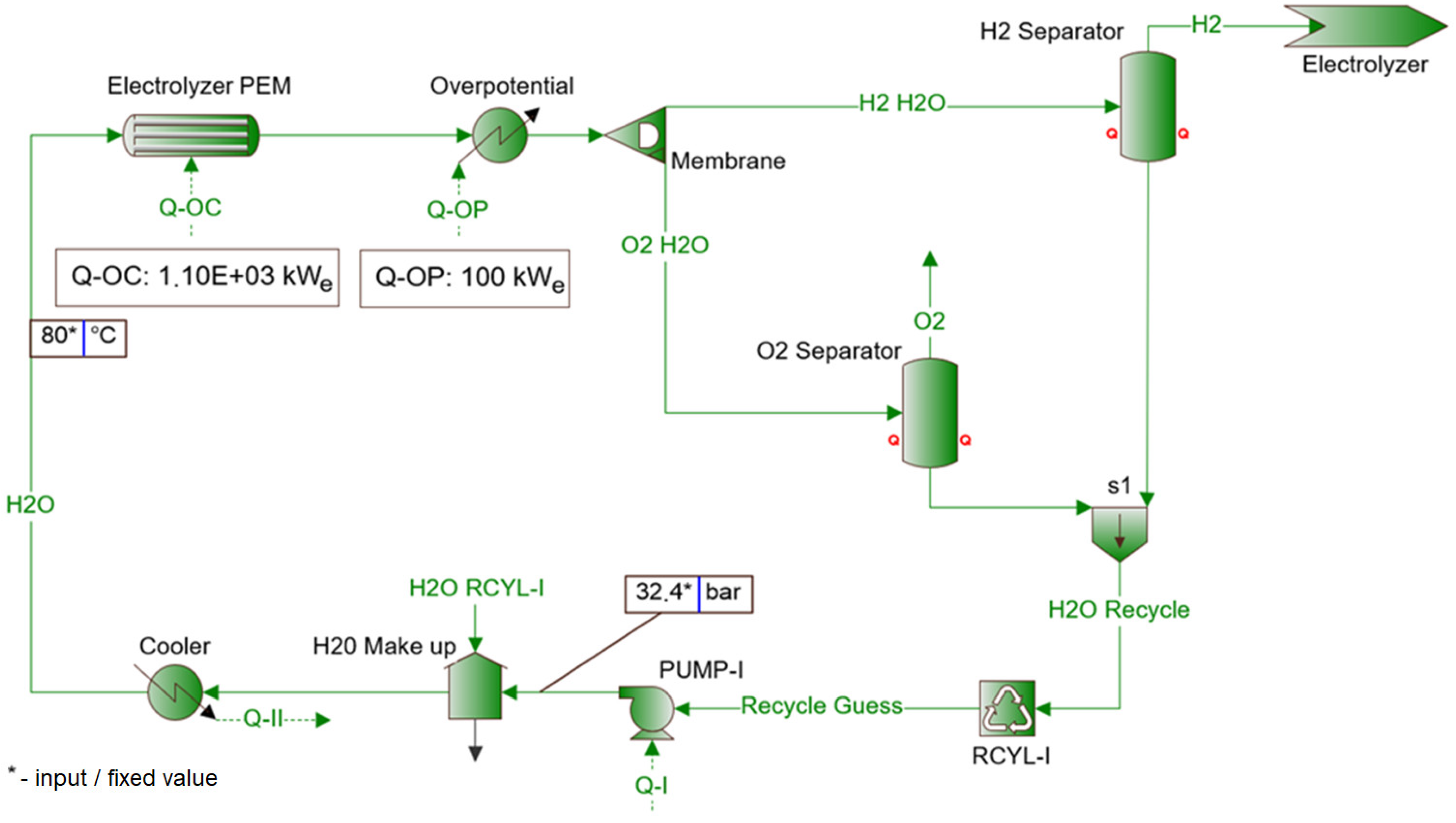
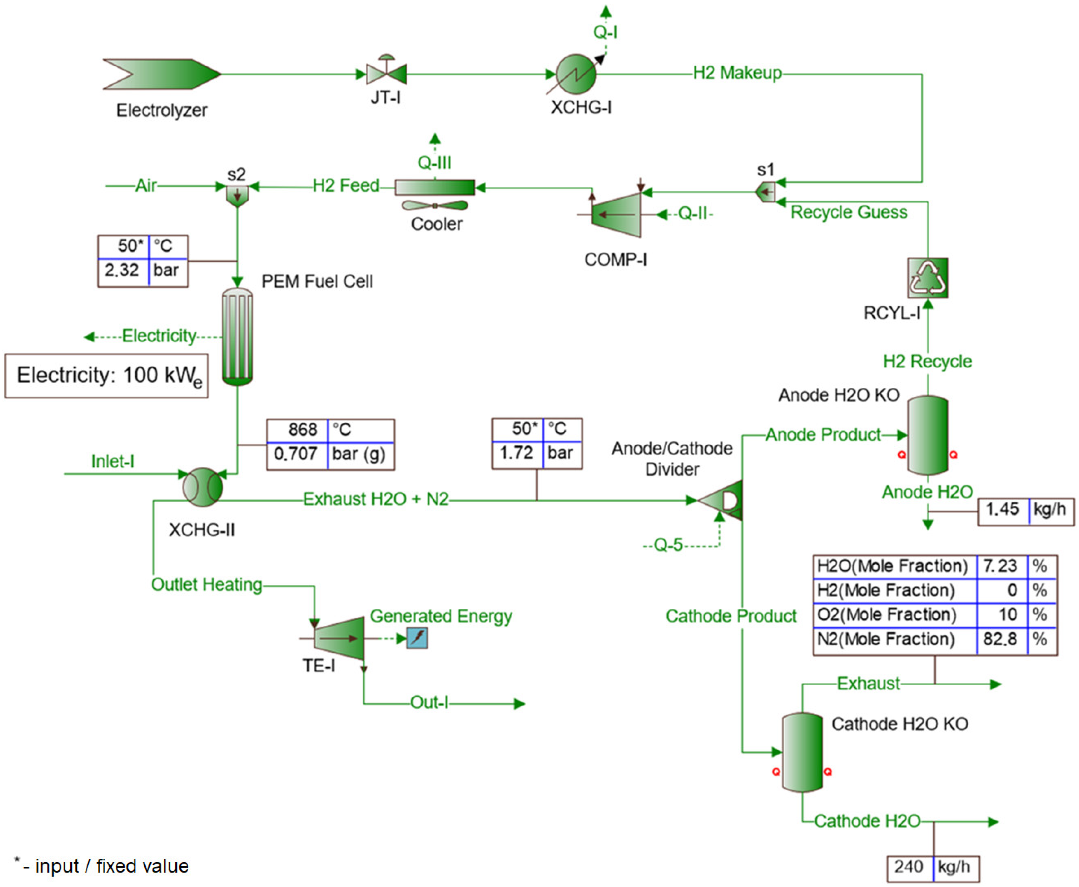
The use of a PEM fuel cell in a combined gas heating system prior to its expansion was considered. The generated electricity was used to produce hydrogen in the electrolyser (Figure 5), which is directed to the fuel cell (Figure 6).

2.2. PRS Input Parameters

In the Section 2.2.1 and Section 2.2.2 the results of the energy balances of the respective reduction stations were compared based on: (i) applied expansion element and (ii) type of input data (static/dynamic). In Section 2.2.3 the results for static simulation of the reduction station with the PEM cell are presented.

2.2.1. Static Simulation Data—PRS with Pressure Reducer/TE

Static simulations were carried out on the basis of four different groups of considered natural gas stations, depending on the gas flow rate and inlet pressure, assuming:
  • Inlet gas temperature ranges from 4 °C to 12 °C with a step 2;
  • Inlet gas pressure ranges from 25 to 55 bar with a step 10;
  • Gas flow rates range from 4000 m3/h to 22,000 m3/h with a step 4000;
  • Constant temperature at the outlet, 5 °C;
  • Constant pressure at the outlet, 8 bar.
Input data are summarized in Table 3.

2.2.2. Dynamic Simulation Data—PRS with Pressure Reducer/TE

Dynamic simulations were performed for five representative reduction and measurement stations, named as A, B, C, D, and E. This PRS is characterized by various operational parameters listed in Table 4 and Table 5. Due to the lack of information, the outlet gas temperature 5 °C at each PRS was assumed to be the most pessimistic from the energy point-of-view.
In practice, turboexpanders are characterized by the minimum gas flow rate through the expander, below which the reduction system with TE is automatically shut down and switched to the line with a reducer. The minimum value is 3000 m3/h, therefore stations with lower nominal gas flow rate values are not included in further analyses (Table 4 and Table 5—B, C and D stations) [1,15,16]. The simulations were carried out for stations with higher gas flow rates marked as A and E.

2.2.3. Static Simulation Data—PRS with TE and PEM Fuel Cell

A static simulation was performed for a period of one year, characterized by constant values: expansion from 45 bar to 15 bar; inlet gas temperature 6 °C; gas flow rate through the station 22,000 m3/h; the composition of the inlet gas is the same as for strings without the fuel cell. Water stream parameters directed to the electrolyser are kept at a constant level—the flow is 25,000 kg/h; the temperature is 80 °C, and the pressure is 32.4 bar. It was assumed that the fuel cell would generate a constant power of 100 kWe. The hydrogen temperature on the inlet to electrolyser was assumed as 50 °C and the pressure as 2.32 bar.

3. Results

3.1. Static Simulation Results—PRS with Pressure Reducer/TE

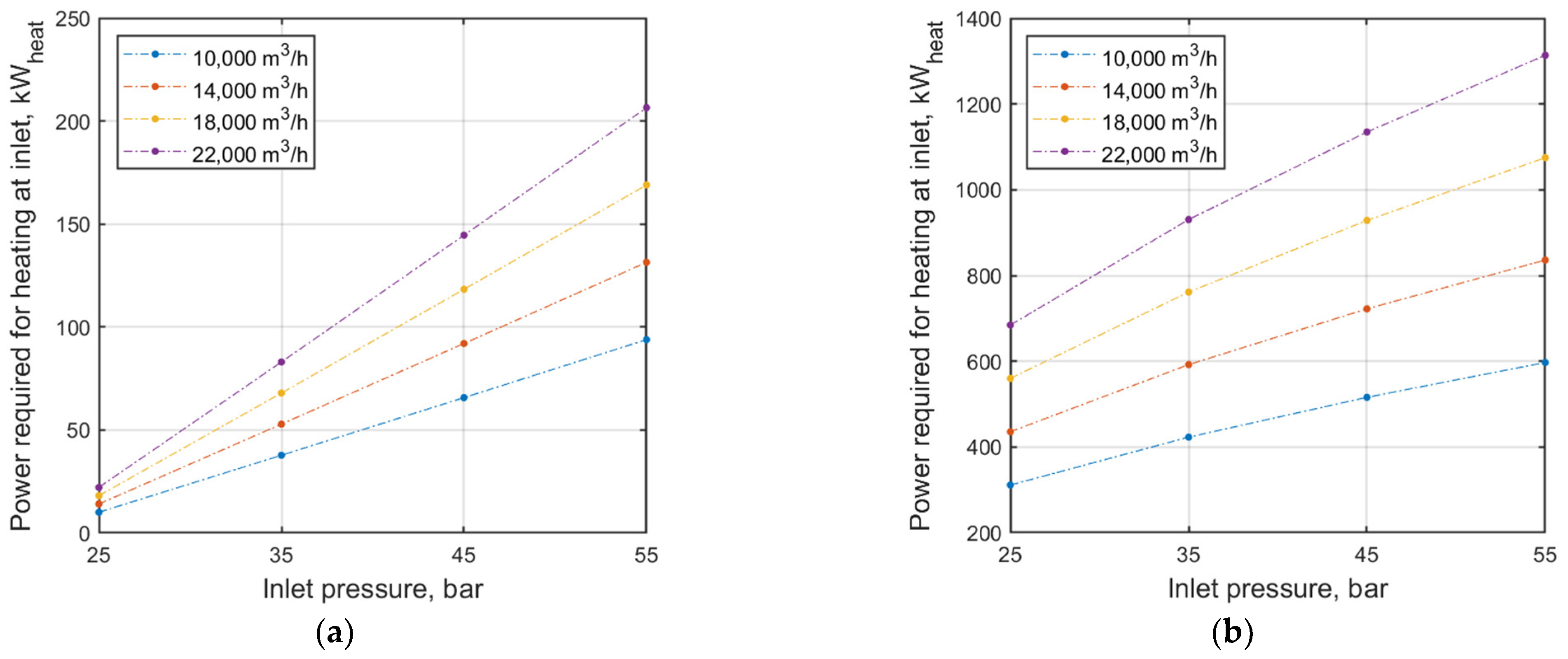
For static input parameters (Section 2.2.1), the analysis shows the change in energy demand for variant gas flow rates of the PRS with a reducer (Figure 7a) and turboexpander (Figure 7b). The analysis of the results shows that the energy consumption increases with the increase of the gas flow through the PRS. The PRS with a turboexpander requires about 30 times more thermal energy to heat the gas at a low inlet pressure (25 bar) and a gas flow rate through the station of 10,000 m3/h compared to the PRS with a pressure reducer. For the highest inlet pressure tested (55 bar) and the highest gas flow rate through the station of 22,000 m3/h, this value is approximately six times higher than for the PRS with a reducer.
In addition, changes in energy demand for variant inlet gas temperature to the PRS with a reducer (Figure 8a) and turboexpander (Figure 8b) were analyzed.
As the temperature of the natural gas at the inlet to the PRS increases, the energy demand for gas preheating decreases. For a natural gas inlet pressure of 55 bar and a gas temperature of 4 °C, the amount of thermal energy that must be supplied to the system with TE is ~1320 kWheat. For the system with the pressure reducer, the supplied thermal energy is ~210 kWheat. With the pressure drop, this difference becomes larger. For higher temperatures and lower gas pressures at the inlet to the PRS with a reducer, the inlet temperature can by high enough that it will not be necessary to heat the natural gas, and thus it will not be required to supply thermal energy. It can be necessary when using TE.
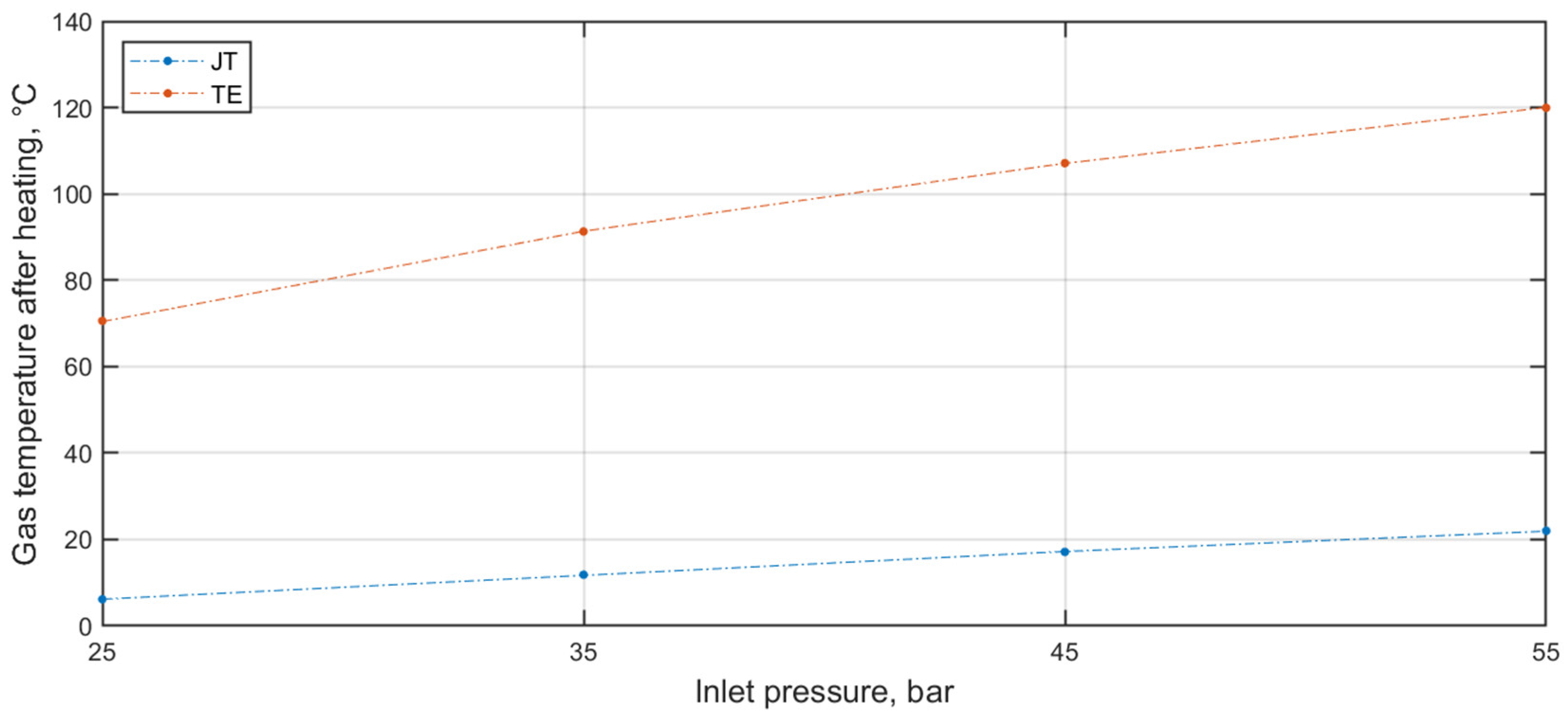
The temperature to which the gas should be heated depends, among other things, on the gas pressure at the inlet. This relationship is shown in Figure 9. The temperature increases with inlet pressure increase. The difference in the preheated gas temperature in both systems decreases with increasing pressure.
The electric energy generated by the turboexpander increases with the increase in the gas flow rate through the PRS, which results directly from the construction and principle of operation of the turboexpander (Figure 10).
Figure 10 shows that with a gas flow of 10,000 m3/h and an inlet pressure of 25 bar, the TE generated 260 kWe. After increasing the inlet pressure to 55 bar, for the same gas flow rates, the TE generated almost twice as much energy; 580 kWe. For the gas flow of 22,000 m3/h and the inlet pressure of 25 bar, 460 kWe were generated, and after increasing the inlet pressure to 55 bar,1020 kWe of electric energy was generated. The amount of energy generated increases with gas inlet pressure and gas flow rate increase. The energy demand for gas preheating also increases proportionally.
The analysis of the scenarios presented in Figure 7, Figure 8, Figure 9 and Figure 10, shows that the inlet gas pressure increase resulted in an increase in both (i) the power needed to preheat the gas and (ii) the power generated by the turboexpander. In the case of natural gas, which has a higher inlet temperature, there is less need to heat it up. As a result, for pressure regulation, the power and energy requirements are reduced. It can be concluded that for higher temperatures and pressures of natural gas at the inlet, the expansion process with TE is more economical.
The annual electricity consumption of the selected PRS was analyzed, considering the use of the produced electricity only for the station’s own needs. The list of devices installed on the representative PRS is presented in Table 6.
Not all equipment installed at the station works continuously. Table 7 presents exemplary values of electricity consumption for selected (variant) gas stations (PRS I and PRS II) developed on the basis of the meter readings in individual months.
Assuming that the equipment listed in Table 6 operates continuously, it is possible to calculate the annual electricity consumption according to the total peak power of all devices at the station (11):
24   h · 365 · 17 , 492   kW e = 153 , 230   kWh e
Based on the data presented in Table 7, for PRS I and PRS II equipped with devices similar to those listed in Table 6, the actual electricity consumption of a gas station with high capacity (~10,000 m3/h) can be estimated at about 15,000 kWhe per year, i.e., with an average installation power per year of 1.71 kWe. For the analyzed scenarios, the PRS with turboexpander was characterized by the lowest power of generated electricity (260.64 kWe) in the case of pressure reduction from 25 to 8 bar (at 10,000 m3/h).
The electricity demand of the station’s equipment is ~1% of the electricity generated by the generator at the PRS with a turboexpander, which excludes justification and profitability of its installation for the sole purpose of the station’s own needs.

3.2. Dynamic Simulation Results—PRS with Pressure Reducer/TE

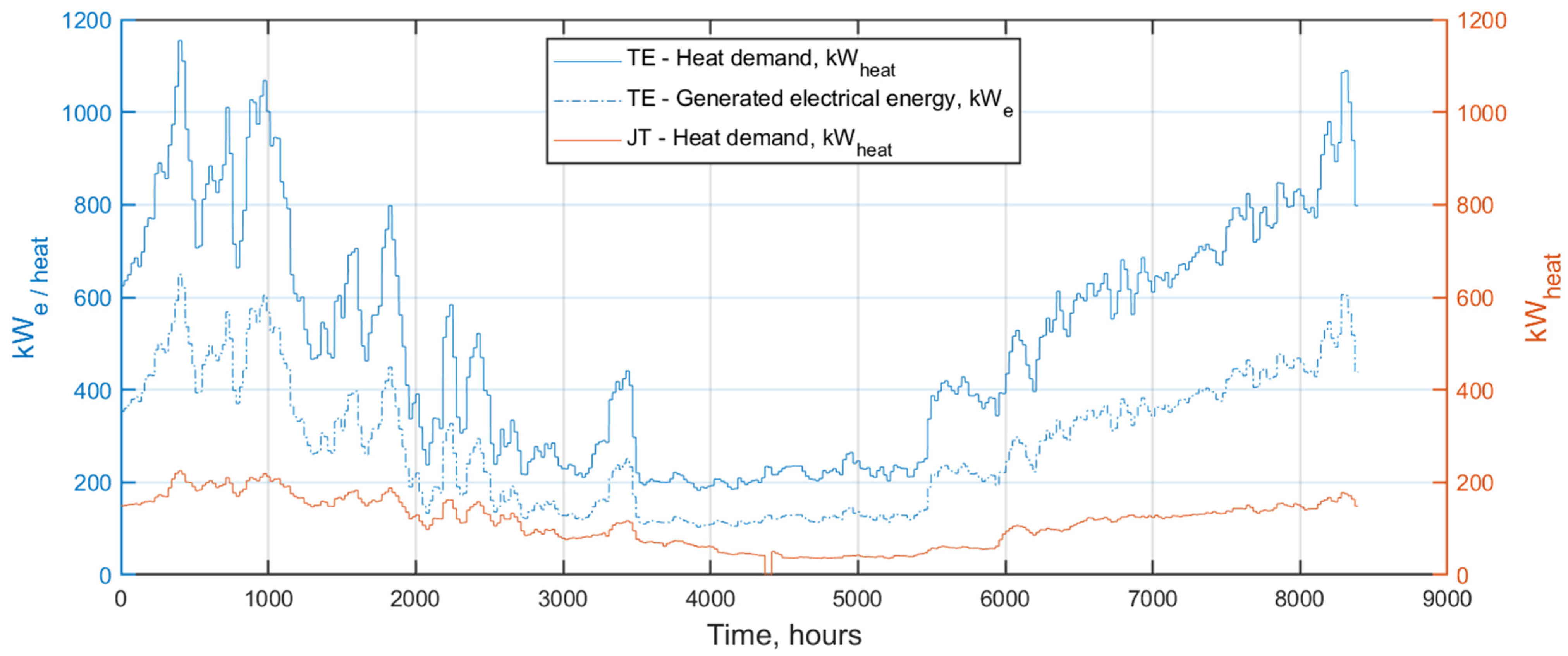
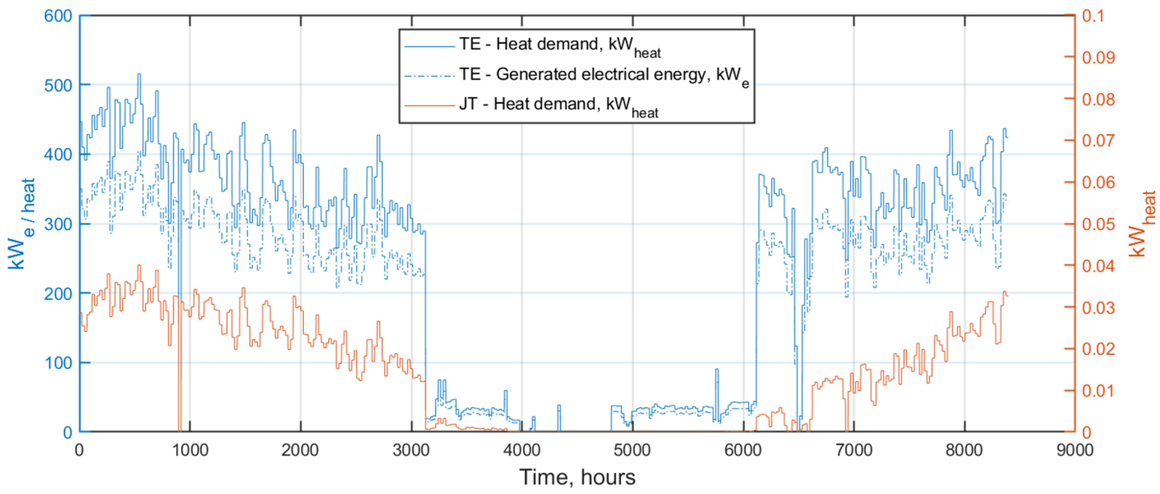
In this section, the sale of the generated electricity was considered. The amount of heat energy required for technological purposes at PRS with a reducer and turboexpander was calculated. Additionally, for the PRS with TE, the amount of generated electricity was calculated. The required thermal energy for preheating and the generated electricity are presented at Figure 11 (Station A) and Figure 12 (Station E).
Natural gas consumption for preheating is subject to seasonal fluctuations. In case of TE application at station A, NG consumption increases during the heating season, which has a major impact on the investment economic balance. The annual demand for natural gas at station A (i) with a pressure reducer is 94,028 m3 (992.00 MWhheat) and (ii) with TE is 418,606 m3 (4416.30 MWhheat). At station A, the pressure was reduced from 30 bar to 8 bar in the heating season. In the off-season, at lower gas flow rates, the pressure was reduced from 30 bar to 16 bar so that electricity production was lower in this period. During the year, TE was operating 8760 h without interruption due to the pressure values at the inlet and outlet of the PRS. The generator produced 2479.303 MWe of electricity during the year (Figure 11).
For the Station E (Figure 12), TE was operating 8760 h without interruption due to the pressure values at the inlet and outlet of the PRS. The generator produced 1656.96 MWe of electricity during the year. Due to the high temperature of the inlet gas and the low expansion rate at station E, it was not necessary to heat the gas before expansion in the case of a system with a reducer. Annually, the PRS with the pressure reducer required 0.12 MWhheat of thermal energy. The PRS with TE required 2089.09 MWhheat. The summarized energy balance is presented in Table 8.
The obtained energy balance results (Table 8) shows that the investment is unprofitable, as the price of resale of electricity to the grid would have to be almost twice as high as the price of natural gas used for technological purposes at the PRS. The possibility of reducing the amount of natural gas needed to heat the gas before expansion by changing the heating source or cogeneration application should be considered.

3.3. Static Simulation Results—PRS with TE and PEM Fuel Cell

Assuming the uninterrupted operation of the electrolyser and the PEM fuel cell, static simulation was performed for such a case (Figure 4 and Figure 5).
For the assumed generated power (100 kWe), the electrolyser required 1100 kWe of power to carry out the electrolysis and 329 kWe to keep a high temperature needed for the reaction. The electrolyser generated 28 kg of hydrogen per hour (245,280 kg/year). The waste heat of water cooling was 80.4 kWheat. The generated hydrogen, after expansion and cooling for injection into the fuel cell, released a thermal power of 1040 kWheat.
During the year, 6570 MWhe of electricity was generated, and the fuel cell generated 876 MWhe. The electrolyser required 10,512 MWhe of electricity.
The comparison of annual energy balances for PRS with a traditional pressure reducer and PRS with TE and PEM fuel cell are presented in Table 9.
In the analyzed scenario, the difference in annual operating costs was PLN 108,571.44 in favor of the system using TE. However, this is a static analysis for optimistically adopted data and it does not take into account the high investment costs—the fuel cell, turboexpander, and the entire additional installation. It is recommended to investigate the payback time, but there is a risk of unnecessarily oversizing the installation.

4. Discussion

In this study, authors compared the selected parameters of PRS with the reducer and turboexpander, with preheating with gas boiler for the same input data.
Energy balances were created, covering pressure ranges from 25 bar to 55 bar, flow rates from 4000 m3/h to 22,000 m3/h and temperatures from 4 °C to 12 °C, assuming a constant pressure value at the station outlet—8 bar. The required energy needed to heat the gas increased with the increase in the set value of the gas flow through the gas station. For an inlet pressure of 55 bar, the system with TE required about 6.5 times more thermal energy than the system with a classic reducer. As the inlet pressure decreased, this difference increased. Required thermal energy also depends on the natural gas temperature at the inlet to the station. The decrease in the inlet temperature is associated with a decrease in the demand for thermal energy. As the pressure of the directed reduction gas increases, the demand for thermal power for its heating increases. It can be concluded that at higher temperatures and pressures of natural gas at the inlet to the PRS, the expansion process will run more economically due to the lower heat demand and the higher amount of electricity produced.
Within this study, a dynamic simulation was developed for the real data of selected stations (A and E) which were characterized with highest flow values among the five analyzed. Station A with a reducer needed 992.00 MWhheat of thermal energy per year for preheating the gas, with the use of a turboexpander it was a value of 4416.30 MWhheat. The power generator produced a total of 2,479,303 MWhe of electricity at station A. In the case of E station with a reducer, the station required 0.12 MWhheat of heat energy due to the high gas temperature at the inlet and a slight reduction. The use of the turboexpander required the supply of 2089.09 MWhheat of thermal energy, and the electric power generator produced 1656.96 MWhe of electric energy.
Due to the dynamic change of natural gas and electricity prices, caused by the current geopolitical situation (war in Ukraine, etc.), the application of TE at both selected stations is not profitable (in Polish conditions). Additionally, the expansion of the natural gas at a temperature of 6 °C from 45 bar to 15 bar at a gas flow of 22,000 m3/h using turboexpander and a PEM fuel cell was considered. During the year, the installation generated 6570 MWhe of electricity with the generator coupled to the TE and 876 MWhe with a PEM fuel cell. The system required 10,512 MWhe of electricity to be supplied to perform the electrolysis process. It is necessary to compare the costs of electricity which is required to run the electrolyser (TE + PEM) with the costs of thermal energy required for preheating in the scenario with a reducer (JT) which required 3504 MWhheat of thermal energy. Comparing the costs of electricity to be purchased to make up for the deficit of electricity needed to power the electrolyser and compare them with the costs of thermal energy needed for pre-heating in the case of a line with a reducer (required 3504 MWhheat of thermal energy). However, the operating costs of the stations are linked to energy prices, and the current geopolitical situation affects the disadvantage of applying such a reduction system.

5. Conclusions

The growing demand for natural gas and the expansion of the transmission and distribution system requires constant improvement of the energy efficiency of the processes which occurs i.e., during pressure reduction of the natural gas transported to the end user and reduction of the operating costs of PRS.
One of the solutions used in the industry is the use of turboexpanders in reduction lines of PRS, which allows for the recovery of energy contained in the natural gas and production of electricity for resale and/or supply to the station’s own needs.
The use of the turboexpander in the reduction line only to obtain energy to meet the own needs of the gas station with the currently available minimum flow values is economically unjustified due to the high investment costs and the production of too much electricity that cannot be used (in Polish conditions).
The obtained results are consistent with the results presented in the studies performed by Osiadacz [17], which present the economic failure of the project for gas prices before the geopolitical changes in 2021. Currently, this value is more than four times higher, electricity prices are also incomparably higher, and electricity resale prices have not increased enough to make the project profitable.
Further profitability analyses for PRS with the application of fuel cells for Polish reduction and metering stations should be considered. The rationale has increased the production of electricity that can be sold, as well as lowered the demand for thermal energy due to the applied cogeneration of preheating with waste heat from the fuel cell.
The most important factor for the profitability of turboexpanders application, instead of traditional natural gas pressure reducers, is the price of electricity and gas (purchase/resale) needed for technological purposes at the PRS. An increase in the resale price of electricity and a decrease in the purchase price of natural gas may contribute to the investment in the future.
It is recommended to perform analyses for the use of turboexpanders at the Polish regasification terminal and gas compressor stations due to the input and output parameters characteristic of these facilities, and thus the high content of energy contained in the natural gas.

Author Contributions

Conceptualization, S.K. and P.B.; methodology, S.K. and P.B.; validation, S.K.; formal analysis, S.K. and P.B.; investigation, S.K. and P.B.; writing—original draft preparation, S.K. and P.B.; writing—review and editing, S.K. and P.B.; visualization, S.K. and P.B.; supervision, S.K. All authors have read and agreed to the published version of the manuscript.

Funding

This work has received funding from the Natural Gas Department at Drilling Oil & Gas Faculty, no. 16.16.190.779.

Conflicts of Interest

The authors declare no conflict of interest.

Nomenclature

Symbols
c p average value of specific heat at constant pressure, J/kg °C
Δ h gas enthalpy change, J/kg
Δ p X H G pressure drop in the exchanger, bar
Hicalorific value of the gas, kJ/m3
Ndemand for thermal power, kWe
N g power generated, We
p ¯ a average value of absolute gas pressure, bar
p n natural gas pressure in normal conditions, bar
Pdthermal power, kWheat
p i n / o u t gas pressure at inlet/outlet of PRS, bar
q b standstill loss, -
Q m gas mass flow, kg/s
Qnnominal gas flow rate through the reducer/turboexpander, m3/h
Q x heat loss, -
S n combustion loss, -
S w chimney loss, -
T 1 , 2 temperature at the inlet/outlet of turbine, °C
T i n / o u t gas temperature at inlet/outlet of PRS, °C
T ¯ i average gas temperature, °C
V p amount of gas used for preheating, m3/h
V ˙ p gas volume flow, m3/h
Greek Letters
η 0 adiabatic efficiency coefficient, -
η g efficiency of the heating system, -
η i z e isentropic efficiency of TE, -
η m mechanical efficiency coefficient, -
η n heating system efficiency, -
ρ n gas density (normal conditions), kg/m3
μ average value of the Joule Thomson coefficient, -
εrequired calculation accuracy, -
Acronyms
ACair conditioner
CaMAaAcontrol and Measurement Apparatus and Automation
CCTVclosed-Circuit TeleVision
EOSequation of state
GCgas chromatography
PEMFCproton-exchange membrane fuell cell
PRSnatural gas regulation stations/natural gas reducing and metering station
SSWiNburglary and panic signaling system
TSOtransmission system operator

References

  1. Chaczykowski, M.; Osiadacz, A.J.; Uilhoorn, F.E. Exergy-Based Analysis of Gas Transmission System with Application to Yamal-Europe Pipeline. Appl. Energy 2011, 88, 2219–2230. [Google Scholar] [CrossRef]
  2. Osiadacz, A.; Chaczykowski, M. Stacje Gazowe: Teoria, Projektowanie, Eksploatacja; Fluid Systems: Warsaw, Poland, 2010. [Google Scholar]
  3. Szargut, J.; Ziębik, A. Podstawy Energetyki Cieplnej; Wydawnictwo Naukowe PWN SA: Warsaw, Poland, 1998. [Google Scholar]
  4. Cascio, E.L.; Ma, Z.; Schenone, C. Performance Assessment of a Novel Natural Gas Pressure Reduction Station Equipped with Parabolic Trough Solar Collectors. Renew. Energy 2018, 128, 177–187. [Google Scholar] [CrossRef]
  5. Rheuban, J. Turboexpanders: Harnessing the Hidden Potential of Our Natural Gas Distribution System. Available online: https://jacobrheuban.com/2009/03/09/turboexpanders-harnessing-the-hidden-potential-of-our-natural-gas-distribution-system/#more-442 (accessed on 16 September 2022).
  6. Ardali, E.K.; Heybatian, E. Energy Regeneration in Natural Gas Pressure Reduction Stations by Use of Gas Turbo Expander; Evaluation of Available Potential in Iran. In Proceedings of the 24th World Gas Conference, Buenos Aires, Argentina, 5–9 October 2009. [Google Scholar]
  7. Galyas, A.B.; Tihanyi, L.; Szunyog, I.; Kis, L. Investigation of Pressure Regulator Replacement by TurboExpander in Hungarian Gas Transfer Stations. Acta Technol. 2018, 4, 5–13. [Google Scholar]
  8. Unar, I.N.; Aftab, A.; Abro, M. Estimation of Power Production Potential from Natural Gas Pressure Reduction Stations in Pakistan Using ASPEN HYSYS. Mehran Univ. Res. J. Eng. Technol. 2015, 34, 301–308. [Google Scholar]
  9. Howard, C.R. Hybrid Turbo Expander and Fuel Cell System for Power Recovery at Natural Gas Pressure Reduction Stations. Master’s Thesis, Mechanical and Materials Engineering Queen’s University, Kingston, ON, Canada, 12 November 2009. [Google Scholar]
  10. WGospodarce.pl. PAP/KG Polski System Przesyłowy Gazu–Ponad 11 Tys. Km Gazociągów. Available online: https://wgospodarce.pl/informacje/111107-polski-system-przesylowy-gazu-ponad-11-tys-km-gazociagow (accessed on 11 September 2022).
  11. pgnig.pl. PGNiG Broszura Informacyjna Wierzchowice. Available online: https://pgnig.pl/documents/29748/961630/PMG+wierzchowice_folder.pdf/c601d1f3-7bfa-46e0-8eed-201926094ff3 (accessed on 20 September 2022).
  12. igg.pl. Izba Gospodarcza Gazownictwa. Available online: https://www.igg.pl/node/264 (accessed on 13 September 2022).
  13. BRE Promax, version 5.0; Bryan Research & Engineering, LLC: Bryan, TX, USA, 2022.
  14. Kowalski, C. Kotły Gazowe Centralnego Ogrzewania Wodne Niskotemperaturowe; Wydawictwo Naukowo-Techniczne WNT: Warsaw, Poland, 1994; pp. 32–35. [Google Scholar]
  15. Kuczyński, S.; Łaciak, M.; Olijnyk, A.; Szurlej, A.; Włodek, T. Techno-Economic Assessment of Turboexpander Application at Natural Gas Regulation Stations. Energies 2019, 12, 755. [Google Scholar] [CrossRef] [Green Version]
  16. Bloch, H.P.; Soares, C. Turboexpanders and Process Applications; Gulf Professional Publishing: Woburn, MA, USA, 2001. [Google Scholar]
  17. Osiadacz, A.; Chaczykowski, M.; Kwestarz, M. An Evaluation of the Possibilities of Using Turboexpanders at Pressure Regulator Stations. J. Power Technol. 2017, 97, 289. [Google Scholar]
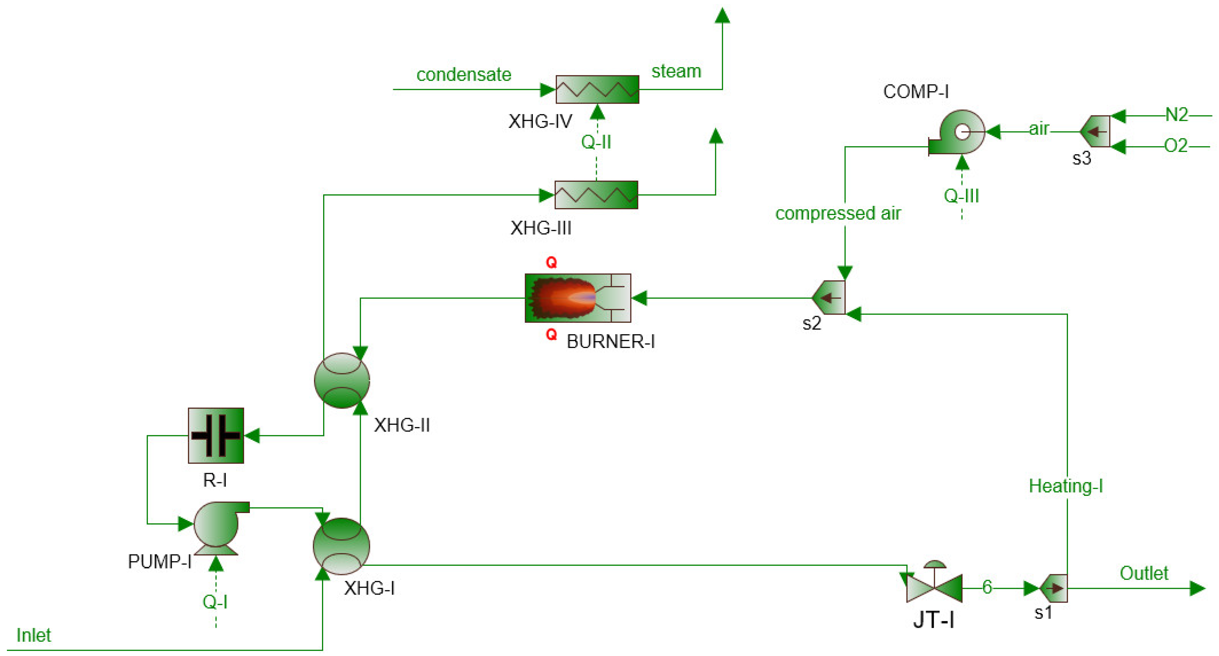
Figure 1. Pressure reduction system with a classic pressure reducer and a gas heating circuit.
Energies 15 08890 g001
Figure 2. Reduction system with pressure reducer (JT-I).
Energies 15 08890 g002
Figure 4. Reduction system with turboexpander (TE-I).
Energies 15 08890 g004
Figure 5. Hydrogen generation with electrolyzer scheme.
Energies 15 08890 g005
Figure 6. Designed PEM fuel cell in a reduction system with a turboexpander (TE-I).
Energies 15 08890 g006
Figure 7. Thermal energy required to heat the natural gas at the inlet to the PRS vs. inlet pressure and gas flow rate: (a) system with a reducer; (b) turboexpander.
Energies 15 08890 g007
Figure 8. Thermal energy required to heat the natural gas at the inlet to the PRS vs. inlet temperature and gas flow rate through the station for: (a) system with a reducer; (b) turboexpander.
Energies 15 08890 g008
Figure 9. Preheated natural gas inlet temperature vs. inlet pressure.
Energies 15 08890 g009
Figure 10. Electric energy produced by TE vs. inlet pressure.
Energies 15 08890 g010
Figure 11. Energy demand for PRS with JT and TE and generated electricity for PRS with TE—Station A.
Energies 15 08890 g011
Figure 12. Energy demand for PRS with JT and TE and generated electricity for PRS with TE—Station E.
Energies 15 08890 g012
Table 1. Iterative determination of JT coefficient μ and specific heat c p .
ParameterSymbolUnitIteration Step
12
JT coefficient μ i °C/bar0.50.59
Average value of absolute gas pressure p bar17.517.5
Average gas temperature T i °C9.2514.75
Calculated JT coefficient μ i + 1 -0.590.585
Calculated specific heat c p J/kg °C2.42.7
| μ i μ i + 1 | -0.90.05 < 0.1
Table 2. Comparison of the obtained results of heat power demand.
ParameterSymbolUnitCalculationsSimulation Results
JT coefficient μ i °C/bar0.5850.592
Thermal power demand P d kWheat20.7322.135
Table 3. Input data.
ParametrSymbolValueUnit
Natural gas compositionCH496.5%mol
C2H60.9
C3H81.8
N20.2
O20.6
Gas density (normal conditions)ρn0.829kg/m3
Heating system efficiencyηn0.85-
Pressure drop in the exchangerΔpXHG0.02bar
Isentropic efficiency of TEηize0.8-
Table 4. Selected monthly averaged values of gas temperature at the inlet to the station and the inlet/outlet gas pressure.
MonthStation
ABCDE
TinpinpoutTinpinpoutTinpinpoutTinpinpoutTinpinpout
°Cbar°Cbar°Cbar°Cbar°Cbar
I5.9129.877.835.1931.512.964.8334.555.595.015.992.506.9943.6925.47
II4.4031.817.714.0231.012.973.6339.835.615.015.342.506.5542.1825.54
III4.1430.987.824.6230.682.964.5537.425.585.014.842.506.6740.9825.56
IV6.0331.177.926.6728.492.946.3435.275.585.014.452.508.1941.7925.62
V8.2729.697.9310.3730.092.939.9433.185.575.011.792.5010.6644.0126.03
VI10.8227.317.8514.7827.852.9314.0236.385.585.011.792.5013.8744.8726.36
VII16.3128.097.8817.4133.082.9217.1135.015.575.011.732.5115.7444.0426.09
VIII18.0034.227.8518.2232.172.9216.9937.755.565.011.712.5216.5544.0026.03
IX15.9029.767.8315.6130.162.9315.4137.655.555.011.792.5116.3345.8325.97
X14.1131.197.8112.8729.962.9412.5937.955.565.012.102.5014.5946.1425.48
XI10.7928.577.789.9430.482.949.8738.005.565.012.602.5211.5444.6526.34
XII8.5231.407.687.3231.532.956.2634.025.615.012.832.588.4843.6326.31
Table 5. Selected monthly averaged values of the gas flow rate Qn and the gas stream used for preheating V p .
MonthStation
ABCDE
QnVpQnVpQnVpQnVpQnVp
m3/hm3/hm3/hm3/hm3/h
I13,40514.1428474.857961.715000.8322,7530.00308
II17,06118.2529925.107501.945520.8557,3890.00279
III11,27915.0825044.248781.763880.7921,2980.00244
IV561210.1120723.277661.362640.6419,6740.00189
V47068.0514392.327401.031160.2110,9550.00087
VI10,26511.0512911.836820.58930.0318300.00005
VII43254.2812351.566880.44640.0024590.00000
VIII42683.4611381.436720.5220.0124590.00000
IX83015.4813731.714830.59140.0842520.00004
X81378.1017802.345610.98660.2717,8940.00059
XI13,47311.8821293.055141.172180.5520,6070.00123
XII15,99413.6127384.447181.865000.9220,8740.00214
Table 6. Power data of the equipment installed at the representative PRS with a gas flow rate of 10,000 m3/h.
EquipmentQuantity
[pcs]
Unit Power
[kWe]
Installed Power
[kWe]
Coefficient of Simultaneity
[-]
Peak Power
[kWe]
CaMAaA cabinet11.201.200.800.96
CCTV and SSWiN cabinet11.001.000.800.80
GC11.501.501.001.50
Higrometers30.300.901.000.90
Boiler12.002.000.601.20
Sockets11.501.500.100.15
Area lighting10.120.120.200.02
Automatic valves20.501.001.001.00
Heating cables32.507.500.806.00
Cathodic protection station12.002.001.002.00
CaMAaA lighting20.120.240.200.05
Area lighting100.121.200.300.36
Measuring cabinets heating60.503.000.601.80
CaMAaA AC11.501.500.500.75
TOTAL 24.660 17.492
Table 7. Monthly electricity consumption for selected 1st stage pressure reduction and measurement station.
Electricity Consumption [kWe]Pressure
Reduction Station
Month
XIIXIXIXVIIIVIIVIVIVIIIIIITOTAL
PRS I1.7431.3641.5191.3961.4431.1221.4871.9100.4742.3951.4111.12417.388
PRS II1.8140.9490.9910.8400.7391.1571.0051.0301.3441.1720.5350.55012.126
Table 8. Energy balance for PRS A and PRS E with variant considered variants: (i) with the use of a reducer (JT) and (ii) turboexpander (TE).
PRS APRS E
JTTEJTTE
Annual natural gas demand for own needs, MWhheat9924416.300.122089.09
Electricity produced, MWhe-2479.30-1656.96
Table 9. Annual energy balance for PRS with a traditional pressure reducer and PRS with PEM fuel cell.
PRS
JTTE + PEM
Annual demand for gas for heating, MWheat3504.00-
Electricity produced (TE), MWhe-6570.00
Produced electricity (PEM), MWhe-876.00
Electricity demand of the electrolyser, MWhe-10,512.00
Total annual costs, PLN1,539,167.041,430,595.60
Publisher’s Note: MDPI stays neutral with regard to jurisdictional claims in published maps and institutional affiliations.