Article

Thermodynamic and Economic Performance Assessment of Double-Effect Absorption Chiller Systems with Series and Parallel Connections

1
PowerChina Huadong Engineering Co., Ltd., No. 201 Gaojiao Road, Hangzhou 311122, China
2
Management School, University of Liverpool, Liverpool L69 3BX, UK
3
Jiangsu Provincial Key Laboratory of Solar Energy Science and Technology, School of Energy & Environment, Southeast University, Nanjing 210096, China
4
School of Science, Aalto University, Aalto, FI-00076 Espoo, Finland
*
Authors to whom correspondence should be addressed.
Energies 2022, 15(23), 9105; https://doi.org/10.3390/en15239105
Submission received: 12 October 2022 / Revised: 14 November 2022 / Accepted: 24 November 2022 / Published: 1 December 2022
(This article belongs to the Special Issue Advances in Solar Photovoltaic Power Generation)

Abstract

:
Absorption cooling technologies converting excess heat and renewable heat resources to cooling energy have shown progress in recent years. In this study, two 400 kW LiBr solution absorption chiller types with series and parallel connected are analyzed over a range of parameter values to better understand their applicability for different uses. Thermodynamic models for the components were constructed and validated. The performance of the chillers related to heat transfer, energy, exergy, and economy performance was comprehensively analyzed. The operating performance was investigated by considering the external variables, including inlet cooling water, chilled water, and inlet steam temperatures and the solution allocation ratio. The results indicate that the parallel connected chiller reaches higher energy and exergy performance than the series-connected chiller, but the heat transfer and economic performance was lower. The coefficient of performance and the exergy efficiency of the parallel chiller were for the reference system 1.30 and 24.42%, respectively. Except for the exergy efficiency, the inlet steam and inlet chilled water temperature had positive impact on the heat transfer, energy, and economic performance, while the inlet cooling water temperature trends the opposite. The sensitivity analysis on solution allocation ratio showed that a higher ratio decreases the heat transfer and economic performance, but considering the energy and exergy performance, a suitable allocation ratio would be 0.54.

1. Introduction

Compared to a conventional vapor compression refrigeration technology, which utilizes high-value energy [1] such as electricity or steam at high temperature and pressure, alternative methods utilizing low-value energy such as waste heat or renewable heat sources are emerging [2]. These include desiccant cooling [3], ejector refrigeration [4], absorption [5], and adsorption [6] cooling technologies.
Powered by thermal energy, solid and liquid desiccant materials are often used in a desiccant cooling cycle to absorb water from incoming air steam, and the cooling effect is obtained by spraying the water to the dehumidified air steam [7]. The ejector cooling cycle works using a thermal compression process realized with a nozzle, chamber, diffuser, and other components [8]. The adsorption cooling system often consists of an adsorbent bed, reservoir, condenser, evaporator, and other components [9]. Recent work on the adsorption cooling cycle has mainly focused on novel adsorbent bed structures [10], adsorbents [11], and total performance [12]. However, the aforementioned three cooling technologies often suffer from the following shortcomings: (1) long recycle period, (2) low cooling capacity, (3) poor energy performance, and (4) limited utilization conditions [13]. Compared to these cooling processes, the absorption cooling approach is an attractive alternative through its following benefits: (1) maturity and reliability, with higher performance, (2) availability for large-scale use, and (3) it is cheaper than other cooling technologies powered by heat [14].
The absorption chillers can be characterized by the operating medium used, e.g., ammonia–water (NH3–H2O) and lithium bromide–water (LiBr–H2O) [15]. Because of its lower evaporation temperature, NH3–H2O refrigeration technology is often utilized in quick freezing and cold storage [16], whereas LiBr–H2O absorption technology has a higher refrigeration temperature and is utilized, e.g., for building cooling with chilled water temperatures >0 °C [17]. In this study, the focus will be on the LiBr–H2O absorption technology.
The absorption cooling processes are further categorized by the driving temperature to single-effect [18], double-effect [19], and triple-effect chillers [20]. Compared to single and double chiller types, the triple effect chiller has a higher energy performance, but would require a high-temperature heat/steam source often based on fossil fuels, e.g., natural gas [21]. The single-effect chiller can operate with lower-grade heat sources, e.g., with solar thermal collectors [22]. The double-effect chiller would require a somewhat higher temperature for operation, e.g., concentrating solar [23] or geothermal energy [24], but would also reach a better economic and environmental performance level than the single-effect chiller [25]. Therefore, a double-effect chiller is employed in this study.
Recent work [26] on double-effect chillers include a range of modeling studies [27] to improve their operating strategy [28], thermodynamic and economic performance analysis [25] including optimization [29], and coupling with different energy systems, e.g., district energy systems [30]. Avanessian et al. [29] investigated series and parallel chillers and found a strong relation between the inlet temperature and mass flow rate on the energy performance. Sergio et al. [31] optimized the structure of double-effect chillers by setting the exergy, heat-transfer area, and cost as single objective function. Comprehensive multi-objective optimization against energy, exergy, and economy have also been carried out [32].
Though the present literature on double-effect chillers is ample [31] the analyses have been incomplete in terms of understanding the effects of chiller interconnections. The present paper therefore incorporates new system features to double-effect chillers by investigating their series and parallel connections by providing new insights into double-effect chillers. Their performance is evaluated against a set of multiple criteria (heat transfer, energy, exergy, economy), but also performing a detailed impact analysis against essential external technical parameters such as chilled water temperature, cooling temperature, driving steam temperature, and solution allocation ratio.
This paper is constructed as follows: Section 2 illustrates the energy flowchart of the chiller and the thermodynamic models of the two types of absorption chillers considered here. Section 3 sets the evaluation criteria including energy, exergy, and economy aspects. Section 4 gives the main results of the analyses and a discussion on the sensitivity of the results against the key parameters. Section 5 gives the conclusions.

2. Energy Flows and Thermodynamic Models of Absorption Chillers

The series and parallel connected chillers are described in the next through energy flowcharts and constructing the corresponding thermodynamic models.

2.1. Energy Flowchart of Absorption Chillers

The energy flowcharts of two absorption chiller types are shown in Figure 1.
In Figure 1a, showing the series-connected chiller, a dilute LiBr solution is fed to the HG (high-pressure generator, state 13) to absorb the heat from the heat source (state 21) after preheating in LTX (low-temperature heat exchanger, state 2) and HTX (high-temperature heat exchanger, state 3). Then, a strong solution (state 16) flows to LG (low-pressure generator) after releasing heat in the HTX (state 14). The first part of the refrigeration vapor from HG (state 17) is condensed in condenser 2, and the heat is totally utilized by the LG to produce a strong solution (state 4) and the second part of the refrigeration vapor (state 7). The strong solution (state 4) is delivered to LTX to release heat and is finally absorbed in the absorber (state 6). The first part of the refrigeration vapor (state 19) and the second part (state 7) are cooled together in condenser 1 by the cooling water (state 25). After throttling (state 8 and 9), the vapor with a lower pressure and temperature can absorb the heat from the returned chilled water (state 27). The refrigeration water is then absorbed by the strong solution in absorber (state 10), and the additional heat is brought out by the cooling water (state 23). Furthermore, the chilled water (state 28) is generated in the evaporator of the absorption chiller.
The main difference of the parallel-connected chiller in Figure 1b and the series-connected chiller is as follows: The dilute LiBr solution from the HTX is divided into two parts; one part is fed to LG (state 30) and the other (state 11) flows to HG, which is similar to the series-connected chiller. Considering the other components of the parallel connected chiller, the energy flowchart in Figure 1b is similar to that of the series-connected one in Figure 1a.

2.2. Thermodynamic Models and Their Validation

The thermal models of the chiller components are described by their mass, solution, energy, and exergy balances. The main energy principles of components are displayed in Table 1 [26].
The heat capacity of components is related to the heat transfer coefficient (U), heat-transfer area (A), and logarithmic mean temperature difference ( ζ ) [33]:
Q i = U i A i ζ i
where i is the ith component of AC. In this study, U is related to heat conduction and heat convection between fluid and wall surface, and the values summarized in Table 2 are based on the references [33,34].
Additionally, the solution allocation ratio (D) defined as the ratio of mass rate of state 11 to state 3 has a huge impact on the performance of the LiBr chiller:
D = m 11 / m 3

3. Evaluation Criteria

For a more detailed evaluation of the performance of the proposed absorption chiller types, a set of indicators related to heat-transfer area, energy, exergy, and economic performance are defined next.

3.1. Heat-Transfer Area

The total heat-transfer area of the AC ( H T A t o t a l ) is the sum of the heat-transfer area for each component ( H T A i ):
H T A t o t a l = 1 i H T A i

3.2. Energy

The coefficient of performance (COP) describes the energy performance of the AC. The COP is calculated as the ratio of the cooling output from the evaporator to the thermal energy input into the HG, and the electricity consumption of the solution pump ( E p u m p ):
COP = Q e v a / ( Q H G + E p u m p )
E p u m p = { ( m 1 ( h 2 h 1 ) ) / η p u m p , ( Series - chiller ) ( m 1 ( h 2 h 1 ) + m 11 ( h 12 h 11 ) ) / η p u m p , ( Parallel - chiller )
where Q e v a and Q H G are the chilled water output of the evaporator and thermal input of HG, respectively. η p u m p is the efficiency of the pump.

3.3. Exergy

The exergy efficiency ( η e x ) is employed to examine the exergetic performance of the AC by considering the energy quality of fuels and the products which are easily affected by temperatures.
η e x = E x e v a / ( E p u m p + E x H G )
E x e v a = Q e v a ( T 0 T 28 1 )
E x H G = Q H G ( 1 T 0 T 21 )
where E x e v a and E x H G are the exergy output of evaporator and exergy input of HG, respectively. T0 is the temperature in standard conditions (25 °C).

3.4. Economy

The annual total cost (ATC) is often used to evaluate the economic performance of AC [34]. The following assumptions are used in the economic analysis: (1) The service lifetime (n) is 25 years; (2) the interest rate (j) is 10.33% [31]; (3) the daily operation time is 6 h [34].
The ATC is related to the annual capital cost (ACC) and annual operation cost (AOC) as follows:
ATC = ACC + AOC
ACC = CRF 1 i Z i
where CRF and Z i are the capital recovery factor and initial investment cost for the ith component, respectively. The initial investment cost for each component is summarized in Table 3.
The CRF is determined by the following equation:
CRF = j ( 1 + j ) n ( 1 + j ) n 1
The AOC is calculated by the consumption of cooling water in the condenser and the absorber (CW), and heating water in HG (HW):
AOC = C H W HW + C C W CW
where C H W and C C W are the unit costs of heating and cooling water, 3.0 USD/t and 0.0195 USD/t in this study, respectively [31].
During the simulation process, the Engineering Equation Solver software (EES) is selected to evaluate the performance of two chiller types, due to the defaulted thermodynamic properties of LiBr solution, steam, and other working media [36].
For validation of the present simulation model, its results were compared to those in [33], with similar initial conditions (Table 4), heat-transfer coefficients (Table 2), and operating details in [33]. The relative errors of heat capacities of components are given in Table 5, and the average relative error is <4%, which demonstrates adequate accuracy of the present thermal model.

4. Results

Based on the thermodynamic models and evaluation criteria, the performance of Acs is discussed next. The inlet and outlet temperatures of solar steam are 150 °C and 140 °C, while other working parameters are listed in Table 4, and the solution allocation ratio for the parallel-connected chiller is determined as 0.54, as discussed in Section 4.2.3 (sensitivity analysis of the solution allocation ratio).

4.1. Main Results

The performance results of the two AC types are shown in Table 6. Compared to the series-connected absorption chiller, the energy and exergy performance of the parallel connected AC is better: its COP is 1.30 and the exergy efficiency is 24.4%. However, the total heat-transfer area of the parallel one, calculated by Equation (1), is higher, which results in a higher annual investment cost (Table 5) and total annual cost. The annual total cost of the series-connected chiller is 84% of the cost of the parallel one. The performance of each state is summarized in Table A1.
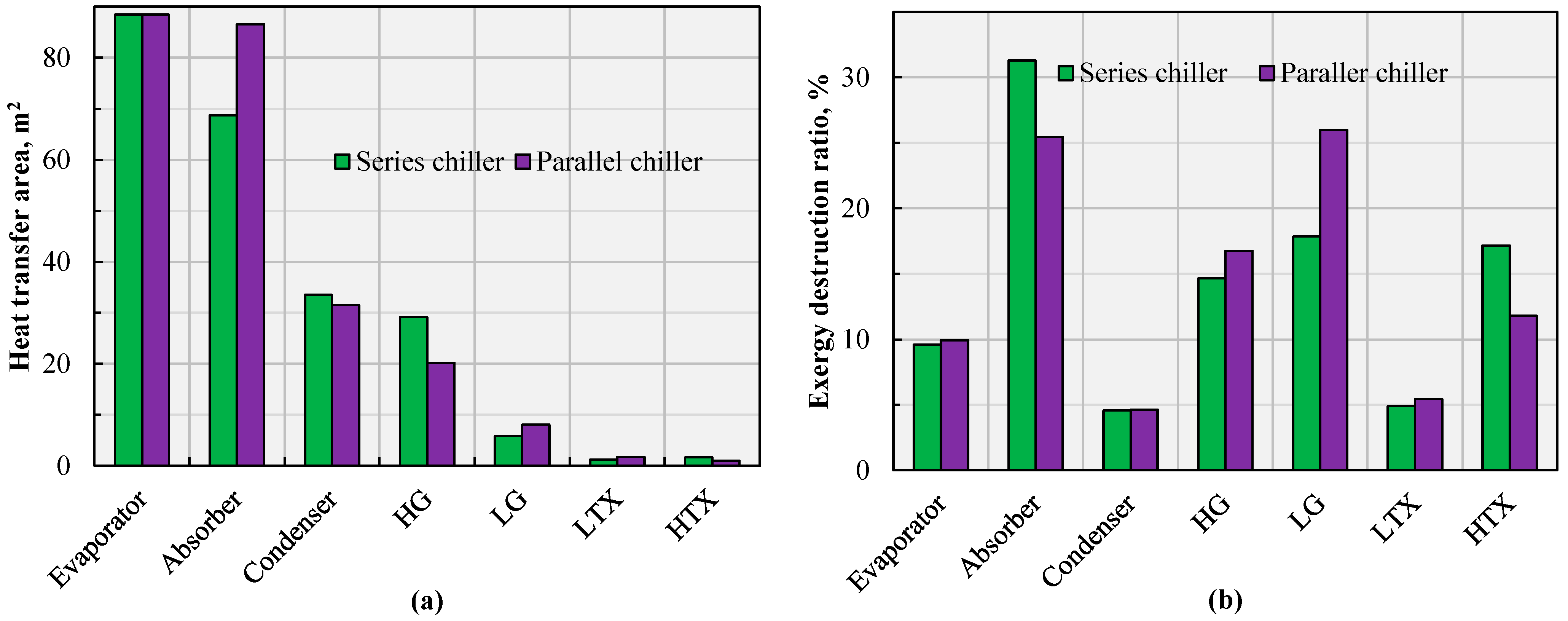
The heat-transfer area and the exergy destruction ratio for the components in the chiller is shown in Figure 2. The size of the heat-transfer areas (Equation (1) and Table 1) shown in Figure 2a descend in the following order for both chillers: evaporator, absorber, condenser, HG, LG, LTX, and HTX. In the parallel chiller, a part of the solution is fed to the LG, leading to a smaller HTX than in the series-connected one, while the series chiller needs more heat-transfer area. On the other hand, the evaporator and absorber area takes the highest proportion of the total heat-transfer area, or, 68.74% and 73.65% for series and parallel chillers, respectively.
Regarding the exergy losses in Figure 2b, the largest loss in the series-connected chiller occurred in the absorber, at 26.01% of the total exergy loss, but in the parallel chiller, the largest loss was in the LG (31.29%). The lowest exergy losses were found in the condenser, being almost the same for the two chiller types (4.56% and 4.64%). The exergy destruction ratios in the LG and HG are higher for the parallel type than for the series type.

4.2. Effect of External Parameters

The performance of the chiller is affected by external parameters such as the cooling temperature, inlet solar steam temperature, and solution allocation ratio. Below, we have examined the impacts of cooling and inlet heating temperatures on the heat-transfer area, COP, exergy efficiency, and annual total cost. With the 400 kW cooling capacity, the external parameters in Section 4.2 are summarized in Table 7. To ensure the normal operating of LiBr solution, the solar steam temperature is varied from 114 °C to 192 °C, when T23 and T25 range from 25 °C to 35 °C, and in Section 4.2.2, the range of the solar steam temperature is 98 °C to 158 °C.

4.2.1. Impact of Cooling Water Temperature (T23, T25)

(1)
Heat-transfer area
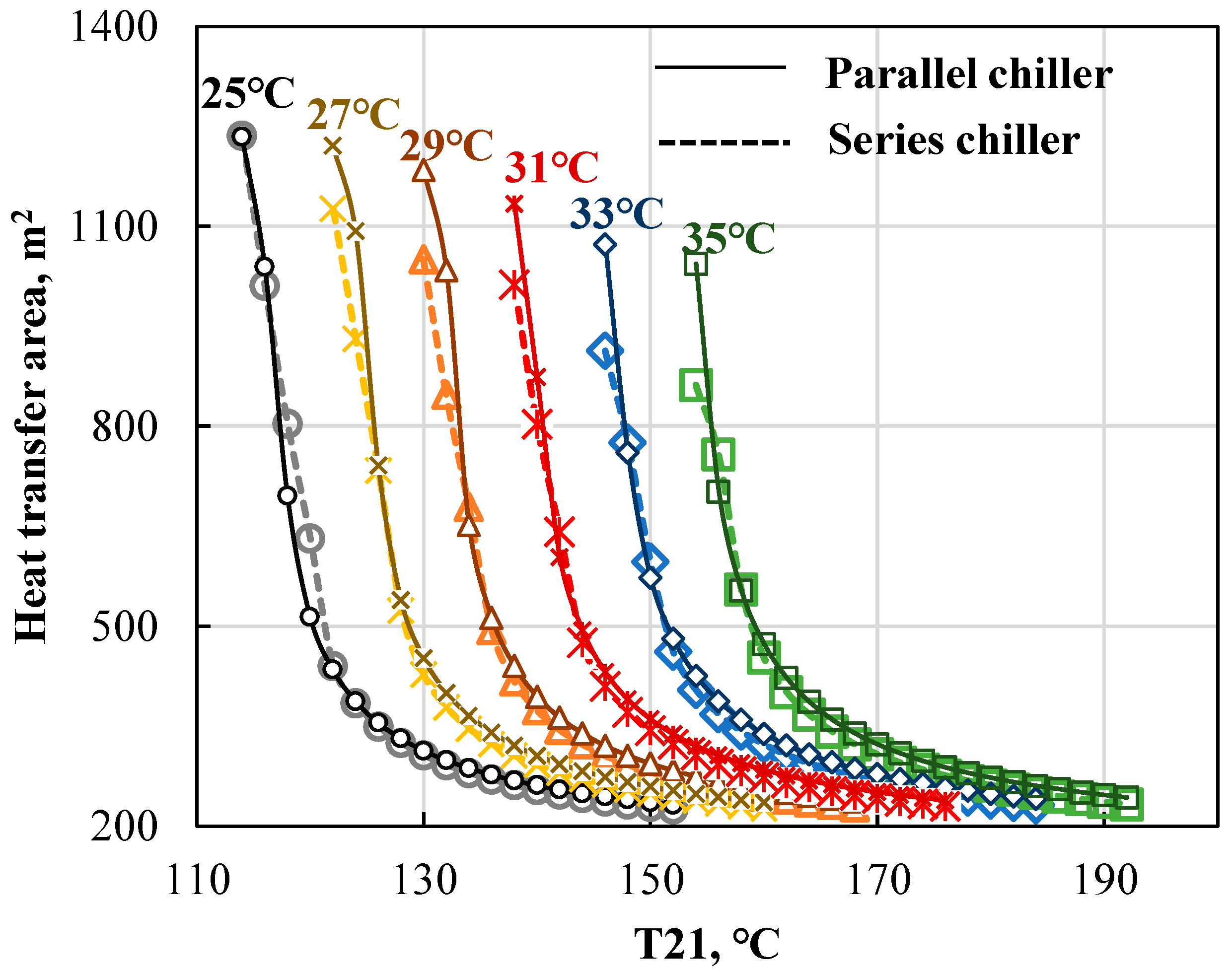
Figure 3 shows the sensitivity of the total heat-transfer area required with the two types of absorption chillers against the cooling temperature and inlet steam temperature. For each curve shown in Figure 3, the HTA drops close to 60% within the first 25% change of the inlet steam temperature (T21). For the next 75% change of T21, the heat-transfer area decreases slowly, varying from 400 m2 to 200 m2.
With constant chilled water output of 400 kW, the higher inlet steam temperature reduces the required heat-transfer area, while a higher cooling water temperature has a negative influence. A higher inlet steam temperature yields a larger temperature difference, leading to higher heat efficiency, while the heat in the absorber and condenser is difficult to release at a higher cooling temperature. Compared to the other five curves, when the cooling temperature is 35 °C, the heat-transfer area variation is lowest, at 1.92%, when the inlet steam temperature increases by 1 °C. Compared to the chiller connected in series, the parallel connected absorption chiller needs more HTA with the same external parameters: for example, when the cooling temperature is 35 °C, the HTA for the parallel one is 4.61% higher than that for the series-connected one.
(2)
COP
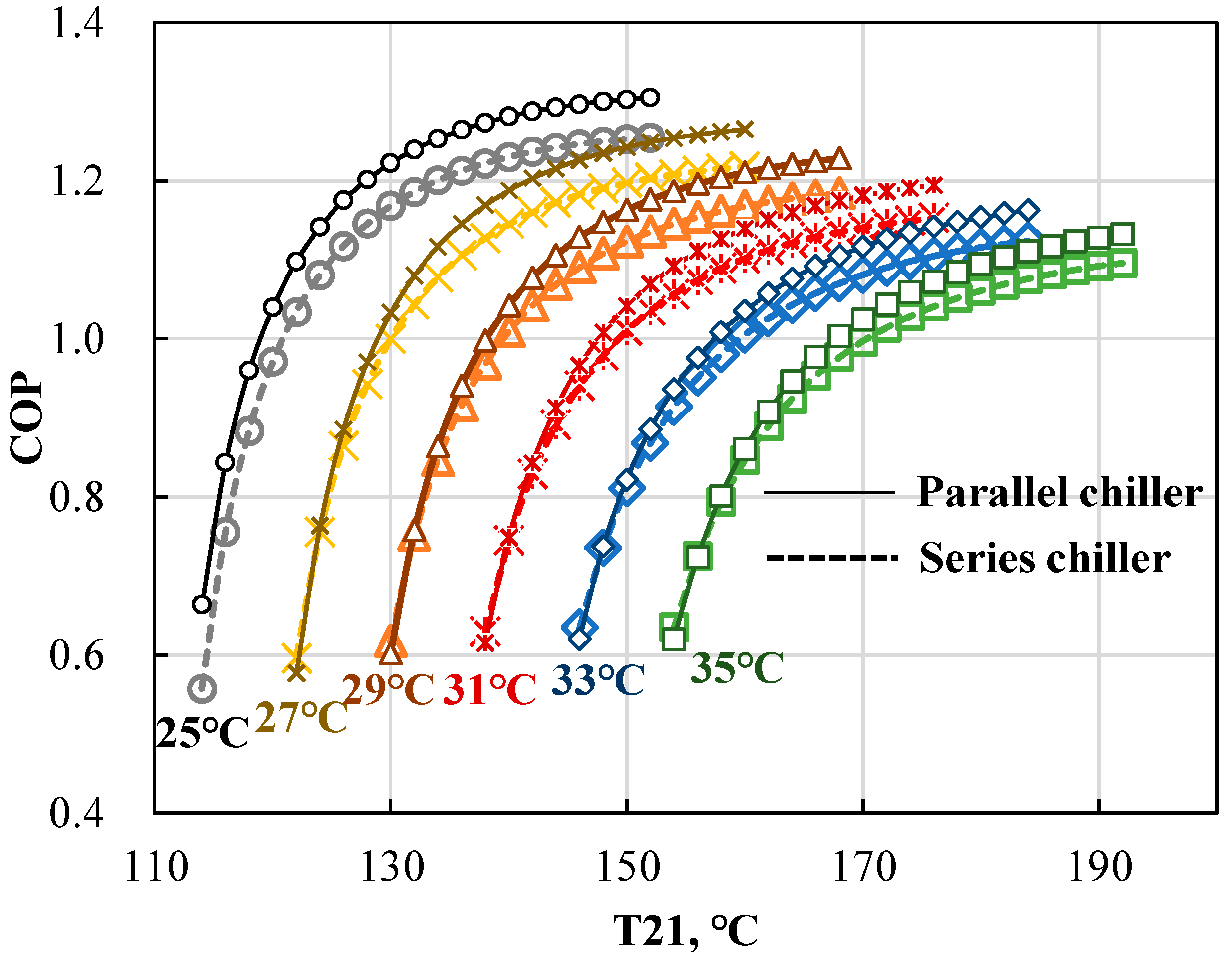
The variation in the energy performance described by the COP as a function of the cooling temperature and inlet steam temperature is shown in Figure 4. The inlet steam temperature and cooling water temperature have the opposite effects on the COP: a higher steam temperature improves the COP, while a higher cooling water temperature leads to lower energy performance. Increasing the cooling water temperature from 25 °C to 35 °C for the series chiller increases the COPs by up to 125%. The variation range of the COP with the inlet steam temperature is highest, with a low cooling water temperature (e.g., 25 °C).
Comparing the series and parallel chillers, the maximum COP for the parallel type is 1.30, when the cooling water temperature is 25 °C, which is slightly higher than the COP of the series chiller (1.25). Because of a higher heat-transfer area, the peak value of the COP of the parallel-connected chiller is always higher than that of the series-connected chiller for different cooling water temperatures.
(3)
Exergy efficiency
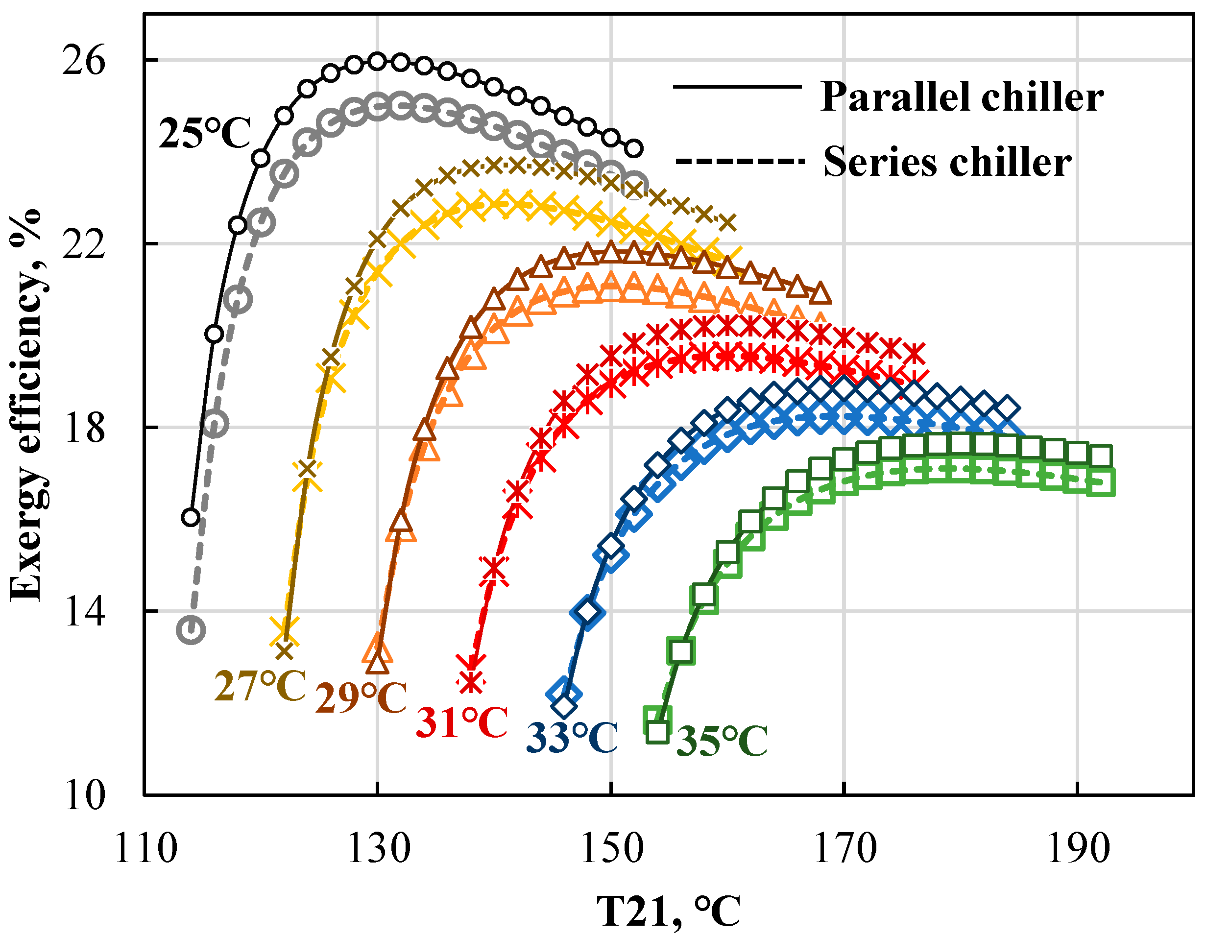
The exergy efficiency as a function of the cooling temperature and inlet steam temperature is displayed in Figure 5. As the inlet steam temperature increases, the exergy efficiency of the absorption chiller first increases to a maximum value, then starts to decline. This is because the COP increases quickly at first as the inlet temperature increases, but starts to level out at higher inlet temperature. For the range of the series chiller, the exergy efficiencies rise by 71.25%, 59.50%, 52.76%, 48.61%, 46.01%, and 44.45%, respectively, when the cooling water temperature rises from 25 °C to 35 °C.
Maintaining constant exergy efficiency would require a higher inlet steam temperature as the cooling water temperature raises. With a higher cooling water temperature, the heat release in the absorber and condenser components is less effective, which requires a higher inlet steam temperature to overcome this negative impact. Compared to the exergy efficiency values of the series chiller, the parallel-connected one has a higher exergy efficiency than the series-connected one due to its superior energy performance. The maximum exergy efficiency was at best: almost one percent/unit better in the range shown in Figure 5.
(4)
Annual cost
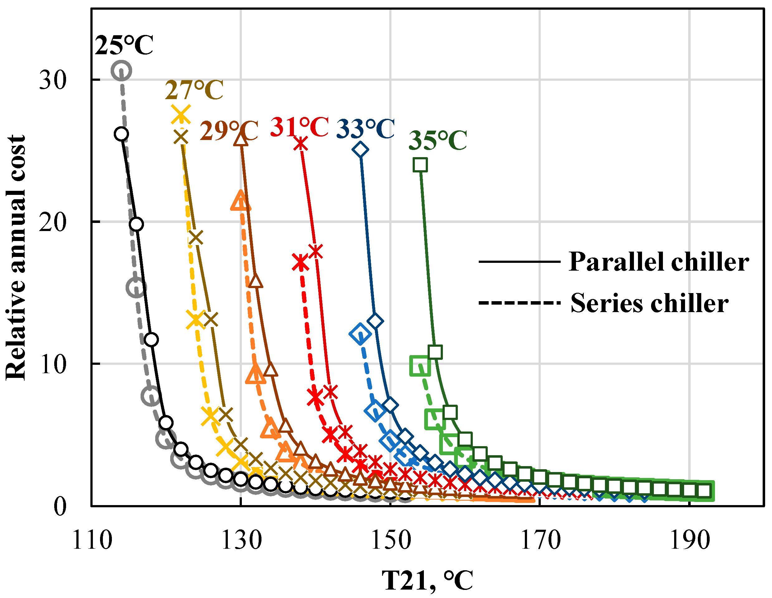
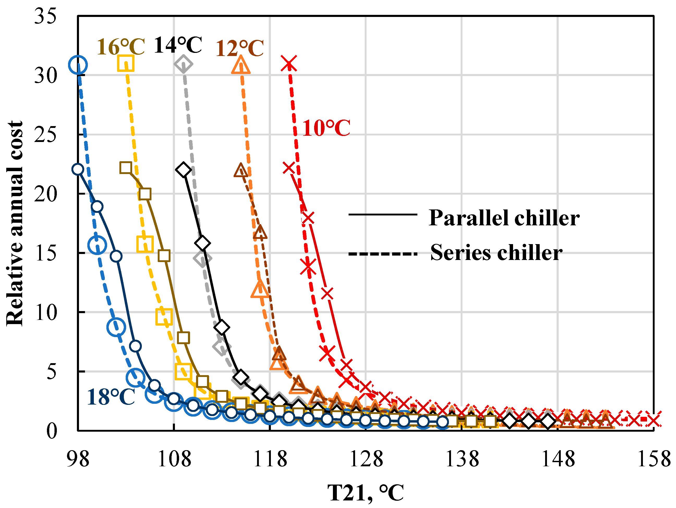
Figure 6 shows the economic performance of the chillers as a function of the cooling temperature and inlet steam temperature. The relative annual cost is calculated based on the ratio of the total annual cost to annual cost with the design condition in Table 6. The relative annual total cost follows the same trend as the total heat-transfer area in Figure 3. This can be explained by the decreasing HTA with increasing steam temperature, and hence lower costs. Additionally, the operating cost decreases due to a higher COP and lower mass flow rate.
Because of the lower cooling water temperature (25 °C), the annual cost in Figure 6 decreases fastest, 96.83%, while the cost decreases 89.18%, when the cooling water temperature is 35 °C. On the other hand, the annual capital cost accounts for a higher proportion of annual total cost, due to the higher investment cost for the components and the lower operation cost. When the cooling water temperature is 25 °C and 35 °C, the proportion varies from 96.75% to 54.93%, and 91.30% to 54.62%, respectively. The relative annual cost of the parallel chiller is lower than that of the series-connected one, but the parallel-connected one has higher cost. This is because the basic annual cost for parallel-type (T21 = 150 °C, T23 = 25 °C), USD 541,939, is higher than the basic annual cost for series type, which is USD 455,428. Due to the higher heat-transfer area, the parallel connected chiller has a lower economic performance than the series connected one, although the energy and exergy performance is higher.

4.2.2. Impact of Inlet Chilled Water Temperature (T27)

(1)
Heat-transfer area
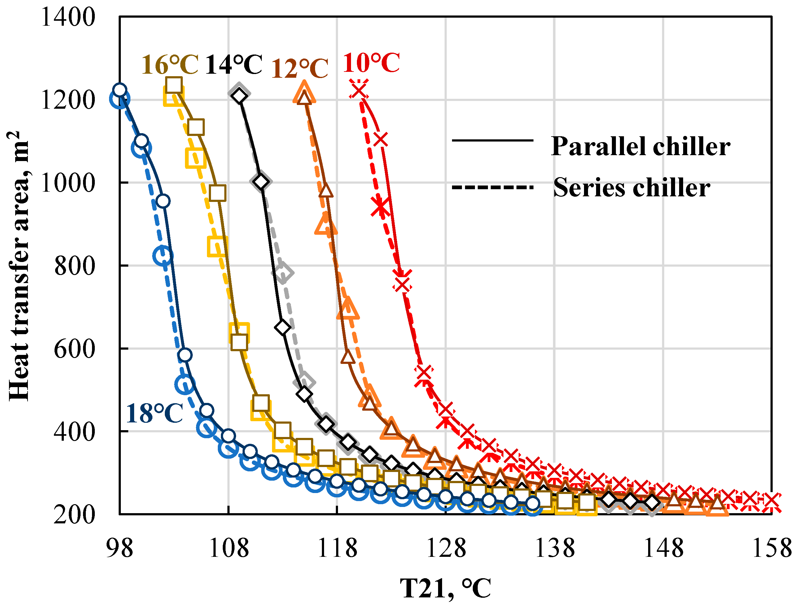
The effect of the chilled water temperature and steam temperature on the heat-transfer area with a constant cooling water temperature of 25 °C is shown in Figure 7. Increasing the inlet steam temperature decreases the required HTA. For example, when the inlet chilled water is set to 18 °C, the heat-transfer area would decline 2.15% for 1 °C of increase in the steam temperature.
The chilled water has an opposite impact on the HTA to the cooling water temperature in Figure 7. With a fixed heat-transfer area, if the chilled water temperature decreases, the inlet steam temperature need to be raised to ensure the set value of the chiller output (400-kW) is met. When the heat-transfer area is set to 250 m2, and if the chilled water temperature is decreased from 18 °C to 10 °C, the inlet steam temperature needs to be increased by 21.3% from 122 °C to 148 °C as a lower temperature difference in the evaporator reduced the heat transfer. Comparing two chiller types, the parallel connected chiller requires slightly more heat-transfer area, the difference being less than 25 m2 in the worst case.
(2)
COP
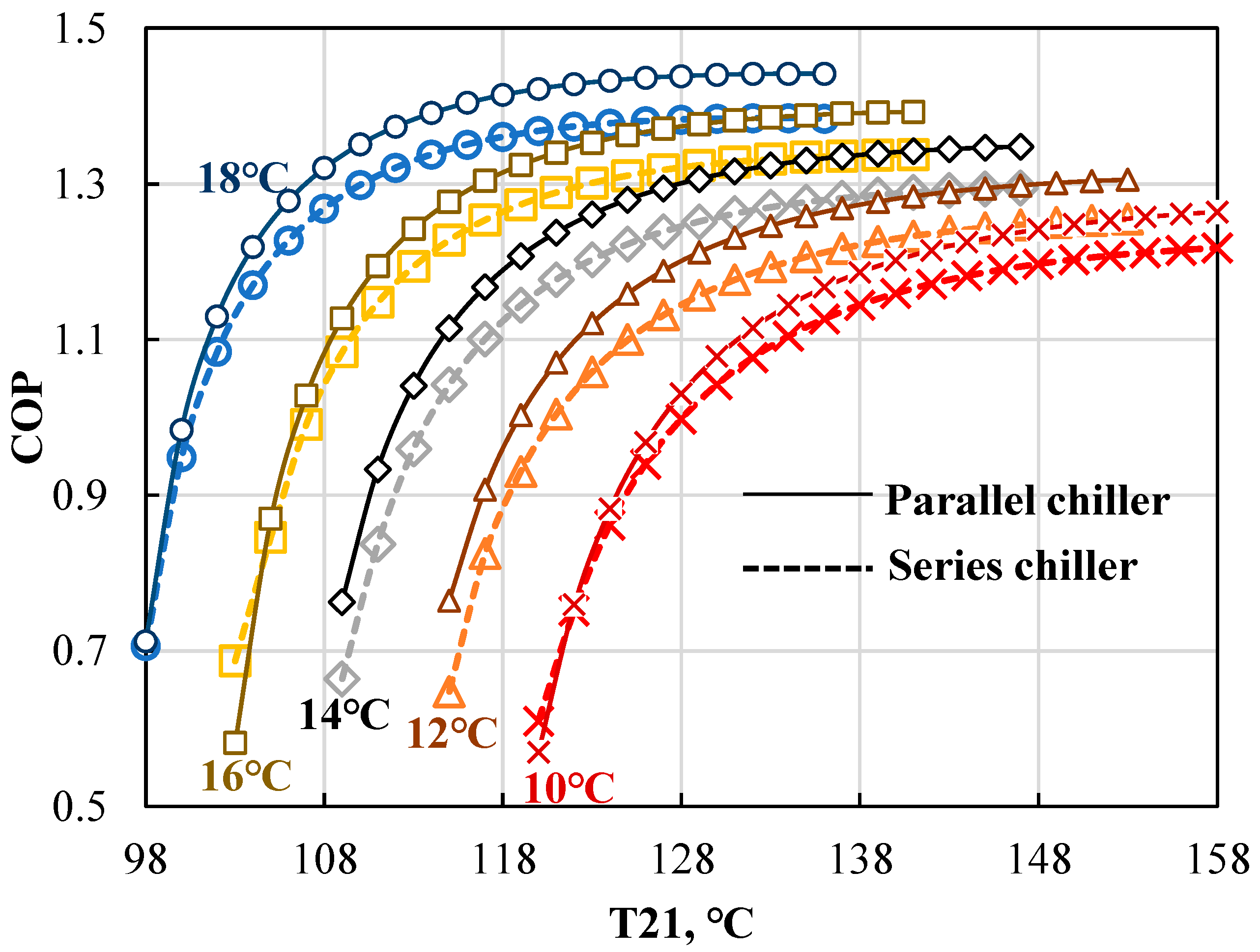
Figure 8 shows that with a constant chilled water temperature, increasing the steam temperature improves the COP. In higher chilled water conditions, the heat contained in the chilled return water is easier to release in the evaporator due to the higher temperature, thus increasing the COP.
Because of the lower heat-transfer area in the series connected chiller, the COP is lower with a fixed inlet chilled water and steam temperature. For example, when the inlet chilled water temperature is 18 °C, the average COP for the parallel chiller is 0.05 units higher.
(3)
Exergy efficiency
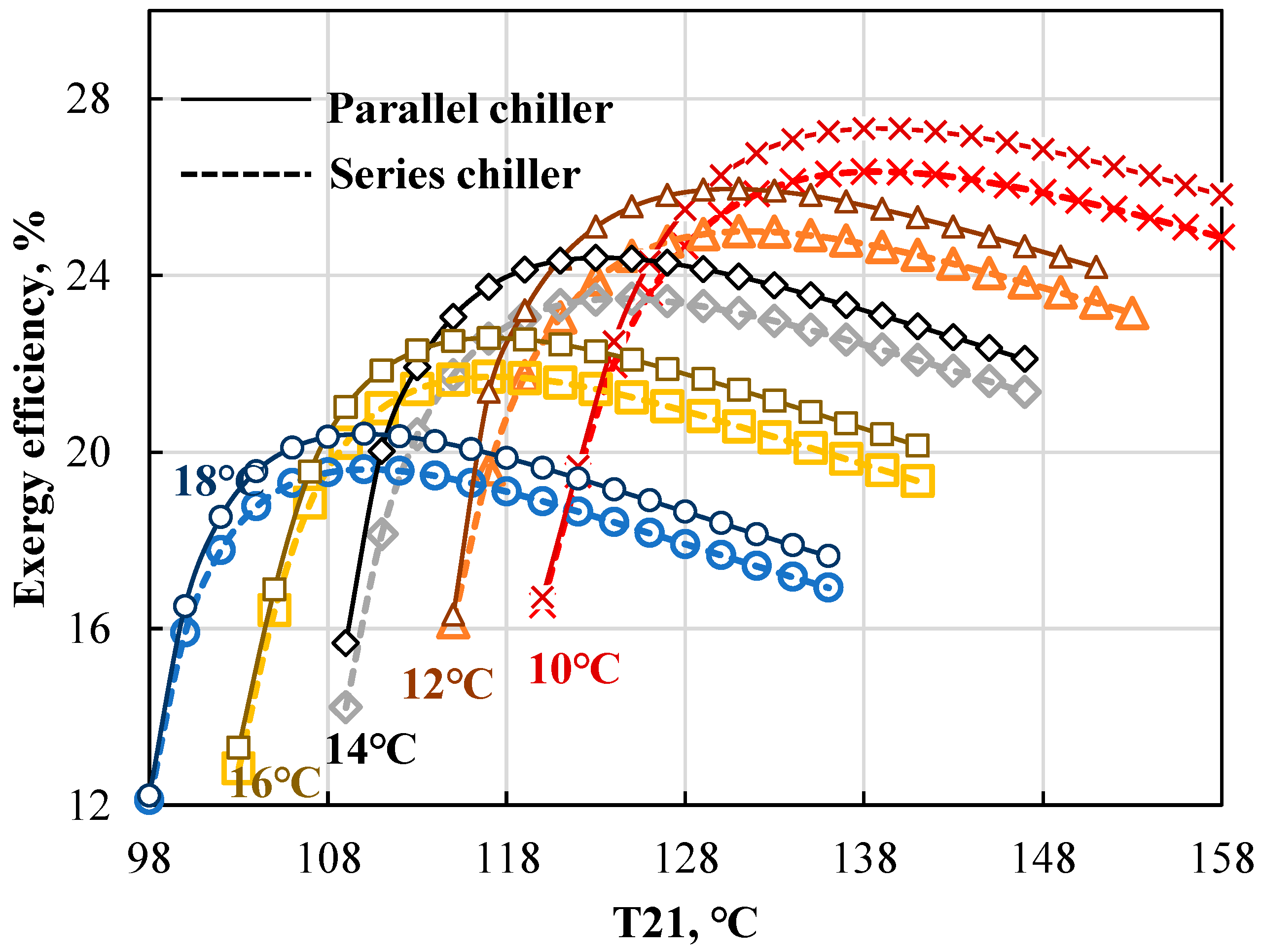
Figure 9 shows the variation of the exergy efficiency with external parameters, including the inlet chilled water temperature and inlet steam temperature.
The exergy efficiency increases to the critical point with a decreasing rate as the inlet steam temperature improves, and then the efficiency declines slightly. On the other hand, as the inlet chilled water increases, the critical point of the exergy efficiency drops: the critical values of the series connected chiller are 26.35%, 25.00%, 23.47%, 21.70%, and 19.61%, respectively, when the chilled water increases for the series chiller. As the chilled water temperature increases, the difference between the chilled water temperature and the standard temperature (25°C) is low, which corresponds a lower energy level.
Because of the higher COP of the parallel connected chiller, the thermal energy needed is also lower. Thus, the exergy efficiency of the parallel chiller is higher than that of the series connected, in practice 1% at most.
(4)
Annual cost
Figure 10 shows the variation of the relative annual cost with inlet chilled water temperature and inlet steam temperature. Keeping the same annual cost, the required inlet steam temperature declines as the chilled water temperature increases due to the higher heat transfer efficiency caused by higher temperature differences in the evaporator. Due to the higher heat-transfer area, the parallel chiller has a higher annual capital cost (Table 5), and it takes a higher share of the annual cost, or 42.23%, 31.49%, 25.65%, 42.64%, and 43.73% of the annual total cost, when the chilled water temperature varies from 10 °C to 18 °C, respectively.

4.2.3. Effect of Solution Allocation Ratio

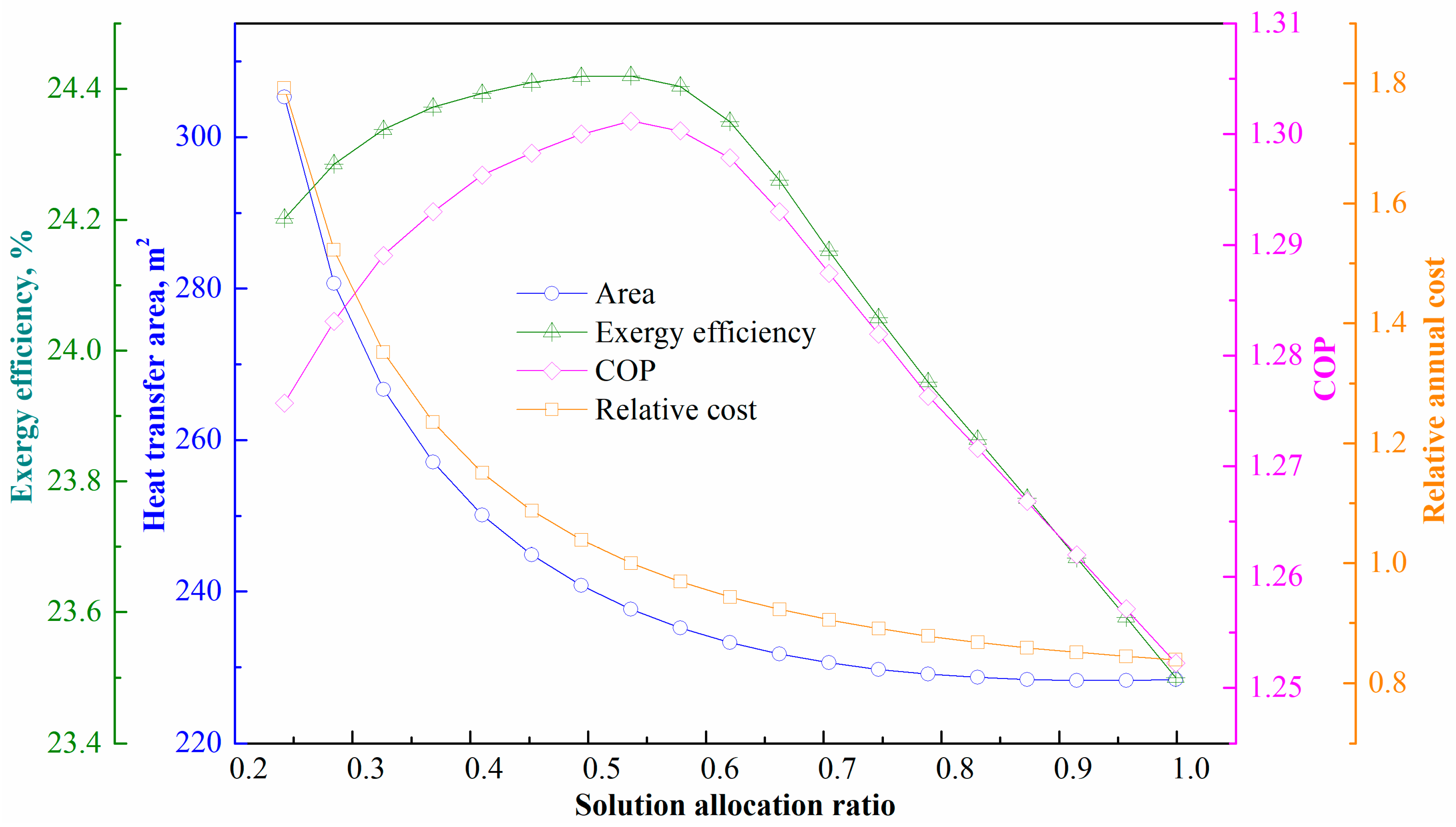
The effect of the solution allocation ratio for the parallel-connected chiller is shown in Figure 11. The ratio is varied from 0.25 to 1.0 (=no solution flows to LG from LTX; HG and LG are connected in series). A lower allocation ratio increases the required heat-transfer area, because the LG needs more heat from condenser 2 to ensure that the fixed capacity is met at lower-allocation ratio conditions. When the allocation ratio increases, the COP improves from 1.28 (ratio = 0.25) to 1.30 (=0.54) but then decreases to 1.25 (=1.0). In Figure 11, the exergy efficiency trends are shown as a function of the solution allocation ratio, similar to the trend of the COP. The exergy efficiency varies 2.9% units over the full range of allocation ratios. Due to a decreasing heat-transfer area vis à vis allocation ratio, the relative annual cost drops with rising allocation ratio. The annual cost decreases by 53.21% from allocation ratio 0.25 to 1.

5. Conclusions

Here, a 400 kW double-effect absorption chiller was analyzed against a set of important design criteria, including heat transfer, energy, exergy, and economic factors. Two types of chillers were considered: a series and parallel-connected chiller.
The main results of the performance comparison are as follows:
  • The parallel-connected chiller type shows a better energy and exergy performance than a series-connected one when the inlet water temperature is at 12 °C, due to its special structure and higher heat-transfer area: the COP and exergy efficiency are 1.30 and 24.42%, respectively. However, the annual cost of the parallel type is 19% higher than that of the series one.
  • The heat-transfer area of the parallel chiller is 228.64 m2 and 237.59 m2 for the series one, respectively. The evaporator, absorber, and condenser of the chiller account for most of the total heat-transfer area: 83.41% in the series type and 86.91%in the parallel one.
  • The exergy destruction ratios of the components for the series chiller in descending order were the absorber, LG, HTX, HG, evaporator, condenser and LTX; for the parallel type, the order of the first four components was the LG, absorber, HG, and HTX.
  • The sensitivity analysis against the key parameters showed the following:
  • For both the series and parallel connected chillers, an increase in the inlet steam temperature decreases the annual total cost due to smaller heat-transfer area required, and improved energy performance. Because of the higher energy level when increasing the inlet steam temperature, the exergy efficiency first rises to a maximum value, and then decreases slightly.
  • Increasing the inlet cooling water temperature decreases the energy and exergy performance of the chillers and increases the needed heat-transfer area and annual total cost, because it is more difficult to release the heat in the absorber and condenser.
  • Increasing the chilled water temperature positively influences the energy, heat transfer, and economic performance, but reduces the exergy performance due to a decreasing energy level.
  • The solution allocation ratio significantly influences the performance of the parallel chiller: as the ratio increases from 0.25 to 1.0, the heat-transfer area and annual total cost decrease by 25.20% and 53.21%, respectively. The energy and exergy performances increase when the allocation ratio rises from 0.25 to 0.54 (maximum value), but then drops almost linearly.
The results indicate that a double effect absorption chiller is an effective choice to convert thermal energy into chilled water for cooling purposes. The next steps in the research could include optimization of the chiller structure, performance analysis for combined heating and cooling demand, and coupling with other novel renewable energy sources.

Author Contributions

Methodology, J.H., Y.Q., Y.C. and J.W.; software, Y.Q.; formal analysis, K.T. and Y.C.; investigation, J.H. and K.T.; resources, Y.C. and P.L.; data curation, J.H. and K.T.; supervision, J.W.; project administration, Y.Q.; funding acquisition, P.L. All authors have read and agreed to the published version of the manuscript.

Funding

This research and Article Processing Charge were supported by National Natural Science Foundation of China (Grant No. 51736006).

Institutional Review Board Statement

Not applicable.

Informed Consent Statement

Informed consent was obtained from all subjects involved in the study.

Data Availability Statement

Not applicable.

Acknowledgments

This research has been supported by National Natural Science Foundation of China (Grant No. 51736006).

Conflicts of Interest

The authors declare no conflict of interest.

Nomenclature

ACAbsorption chiller.
COPCoefficient of performance.
EESEngineering Equation Solver.
HGHigh-pressure generator.
HTXHigh-temperature heat exchanger.
LGLow-pressure generator.
LTXLow-temperature heat exchanger.
Symbols
AArea, m2.
ACCAnnual construction cost, USD.
AOCAnnual operation cost, USD.
ATCAnnual total cost, USD.
CHW/CCWUnit cost of heating/cooling water, USD/t.
CRFCapital recovery factor.
CWCooling water consumption, t.
DSolution allocation ratio.
ExExergy, Kw.
fArea conversion factor.
hEnthalpy, kJ/kg K.
HWHeating water consumption, t.
jInterest rate.
HTAHeat-transfer area, m2.
mMass flow, kg/s.
nService life, years.
QThermal energy, kW.
TTemperature, °C.
UHeat-transfer coefficient, kW/(m2 K).
ZInitial investment cost, USD.
wConcentration of LiBr.
ζLogarithmic mean temperature difference.
ηEfficiency.
Subscript
iith component.
in/outInlet/outlet.
evaEvaporator.
lossLoss.

Appendix A

Table A1. Simulation results of states for two chiller types.
Series-Connected ChillerParallel-Connected Chiller
StatePressure, kPaConcentration,
%
Mass Flow Rate, kg/sPressure, kPaConcentration,
%
Mass Flow Rate, kg/s
10.80353.0871.0990.92451.7921.212
24.14553.0871.0994.14551.7921.212
34.14553.0871.0994.14551.7921.212
44.14562.6570.9314.14560.1021.044
54.14562.6570.9314.14560.1021.044
60.80362.6570.9310.92460.1021.044
74.14500.0854.14500.078
84.14500.1684.14500.168
90.80300.1680.92400.168
100.80300.1680.92400.168
11---4.14551.7920.652
12---72.25751.7920.652
1388.90453.0871.09972.25751.7920.652
1488.90457.4211.01672.25760.1020.561
1588.90457.4211.01672.25760.1020.561
164.14557.4211.0164.14560.1020.561
1788.90400.08372.25700.090
1888.90400.08372.25700.090
194.14500.0834.14500.090
20---4.14551.7920.560

References

  1. She, X.; Cong, L.; Nie, B.; Leng, G.; Peng, H.; Chen, Y.; Zhang, X.; Wen, T.; Yang, H.; Luo, Y. Energy-efficient and -economic technologies for air conditioning with vapor compression refrigeration: A comprehensive review. Appl. Energy 2018, 232, 157–186. [Google Scholar] [CrossRef]
  2. Pang, S.C.; Masjuki, H.H.; Kalam, M.A.; Hazrat, M.A. Liquid absorption and solid adsorption system for household, industrial and automobile applications: A review. Renew. Sustain. Energy Rev. 2013, 28, 836–847. [Google Scholar] [CrossRef]
  3. Khosravi, N.; Aydin, D.; Karim Nejhad, M.; Dogramaci, P.A. Comparative performance analysis of direct and desiccant assisted evaporative cooling systems using novel candidate materials. Energy Convers. Manag. 2020, 221, 113167. [Google Scholar] [CrossRef]
  4. Huang, Y.; Jiang, P.; Zhu, Y. Experimental and modeling studies of thermally-driven subcritical and transcritical ejector refrigeration systems. Energy Convers. Manag. 2020, 224, 113361. [Google Scholar] [CrossRef]
  5. Arabkoohsar, A.; Sadi, M. Technical comparison of different solar-powered absorption chiller designs for co-supply of heat and cold networks. Energy Convers. Manag. 2020, 206, 112343. [Google Scholar] [CrossRef]
  6. Almohammadi, K.M.; Harby, K. Operational conditions optimization of a proposed solar-powered adsorption cooling system: Experimental, modeling, and optimization algorithm techniques. Energy 2020, 206, 118007. [Google Scholar] [CrossRef]
  7. Mujahid Rafique, M.; Gandhidasan, P.; Rehman, S.; Al-Hadhrami, L.M. A review on desiccant based evaporative cooling systems. Renew. Sustain. Energy Rev. 2015, 45, 145–159. [Google Scholar] [CrossRef]
  8. Tashtoush, B.; Algharbawi, A.B.R. Parametric study of a Novel Hybrid Solar Variable Geometry Ejector cooling with Organic Rankine Cycles. Energy Convers. Manag. 2019, 198, 111910. [Google Scholar] [CrossRef]
  9. Li, X.H.; Hou, X.H.; Zhang, X.; Yuan, Z.X. A review on development of adsorption cooling—Novel beds and advanced cycles. Energy Convers. Manag. 2015, 94, 221–232. [Google Scholar] [CrossRef]
  10. Gediz Ilis, G.; Demir, H.; Mobedi, M.; Baran Saha, B. A new adsorbent bed design: Optimization of geometric parameters and metal additive for the performance improvement. Appl. Therm. Eng. 2019, 162, 114270. [Google Scholar] [CrossRef]
  11. Amin, M.; Chetpattananondh, P.; Khan, M.N. Ultrasound assisted adsorption of reactive dye-145 by biochars from marine Chlorella sp. extracted solid waste pyrolyzed at various temperatures. J. Environ. Chem. Eng. 2020, 6, 104403. [Google Scholar] [CrossRef]
  12. Lu, Z. Operation performance study and numerical analysis of the multi-objective adsorption system driven by low-grade heat of solar energy and industrial waste heat. Sol. Energy 2020, 199, 575–584. [Google Scholar] [CrossRef]
  13. Shirazi, A.; Taylor, R.A.; Morrison, G.L.; White, S.D. Solar-powered absorption chillers: A comprehensive and critical review. Energy Convers. Manag. 2018, 171, 59–81. [Google Scholar] [CrossRef]
  14. Arshi Banu, P.S.; Sudharsan, N.M. Review of water based vapour absorption cooling systems using thermodynamic analysis. Renew. Sustain. Energy Rev. 2018, 82, 3750–3761. [Google Scholar] [CrossRef]
  15. Narváez-Romo, B.; Chhay, M.; Zavaleta-Aguilar, E.W.; Simões-Moreira, J.R. A critical review of heat and mass transfer correlations for LiBr-H2O and NH3-H2O absorption refrigeration machines using falling liquid film technology. Appl. Therm. Eng. 2017, 123, 1079–1095. [Google Scholar] [CrossRef] [Green Version]
  16. Shankar, R.; Rivera, W. Investigation of new cooling cogeneration cycle using NH3H2O mixture. Int. J. Refrig. 2020, 114, 88–97. [Google Scholar] [CrossRef]
  17. Chen, Y.; Wang, J.; Lund, P.D. Thermodynamic performance analysis and multi-criteria optimization of a hybrid combined heat and power system coupled with geothermal energy. Energy Convers. Manag. 2020, 210, 112741. [Google Scholar] [CrossRef]
  18. Gomri, R. Simulation study on the performance of solar/natural gas absorption cooling chillers. Energy Convers. Manag. 2013, 65, 675–681. [Google Scholar] [CrossRef]
  19. Fan, Y.; Luo, L.; Souyri, B. Review of solar sorption refrigeration technologies: Development and applications. Renew. Sustain. Energy Rev. 2007, 11, 1758–1775. [Google Scholar] [CrossRef]
  20. Shu, G.; Che, J.; Tian, H.; Wang, X.; Liu, P. A compressor-assisted triple-effect H2O-LiBr absorption cooling cycle coupled with a Rankine Cycle driven by high-temperature waste heat. Appl. Therm. Eng. 2017, 112, 1626–1637. [Google Scholar] [CrossRef]
  21. Mohammadi, K.; Jiang, Y.; Borjian, S.; Powell, K. Thermo-economic assessment and optimization of a hybrid triple effect absorption chiller and compressor. Sustain. Energy Technol. Assess. 2020, 38, 100652. [Google Scholar] [CrossRef]
  22. Chen, J.F.; Dai, Y.J.; Wang, R.Z. Experimental and analytical study on an air-cooled single effect LiBr-H2O absorption chiller driven by evacuated glass tube solar collector for cooling application in residential buildings. Sol. Energy 2017, 151, 110–118. [Google Scholar] [CrossRef]
  23. Zheng, X.; Shi, R.; Wang, Y.; You, S.; Zhang, H.; Xia, J.; Wei, S. Mathematical modeling and performance analysis of an integrated solar heating and cooling system driven by parabolic trough collector and double-effect absorption chiller. Energy Build. 2019, 202, 109400. [Google Scholar] [CrossRef]
  24. Ehyaei, M.A.; Ahmadi, A.; El Haj Assad, M.; Rosen, M.A. Investigation of an integrated system combining an Organic Rankine Cycle and absorption chiller driven by geothermal energy: Energy, exergy, and economic analyses and optimization. J. Clean. Prod. 2020, 258, 120780. [Google Scholar] [CrossRef]
  25. Avanessian, T.; Ameri, M. Energy, exergy, and economic analysis of single and double effect LiBr–H2O absorption chillers. Energy Build. 2014, 73, 26–36. [Google Scholar] [CrossRef]
  26. Talukdar, K.; Gogoi, T.K. Exergy analysis of a combined vapor power cycle and boiler flue gas driven double effect water–LiBr absorption refrigeration system. Energy Convers. Manag. 2016, 108, 468–477. [Google Scholar] [CrossRef]
  27. Yin, H.; Qu, M.; Archer, D.H. Model based experimental performance analysis of a microscale LiBr–H2O steam-driven double-effect absorption Chiller. Appl. Therm. Eng. 2010, 30, 1741–1750. [Google Scholar] [CrossRef]
  28. Alhamid, M.I.; Coronas, A.; Lubis, A.; Ayou, D.S.; Nasruddin; Saito, K.; Yabase, H. Operation strategy of a solar-gas fired single/double effect absorption chiller for space cooling in Indonesia. Appl. Therm. Eng. 2020, 178, 115524. [Google Scholar] [CrossRef]
  29. Chahartaghi, M.; Golmohammadi, H.; Shojaei, A.F. Performance analysis and optimization of new double effect lithium bromide–water absorption chiller with series and parallel flows. Int. J. Refrig. 2019, 97, 73–87. [Google Scholar] [CrossRef]
  30. Wang, J.; Chen, Y.; Lior, N. Exergo-economic analysis method and optimization of a novel photovoltaic/thermal solar-assisted hybrid combined cooling, heating and power system. Energy Convers. Manag. 2019, 199, 111945. [Google Scholar] [CrossRef]
  31. Mussati, S.F.; Gernaey, K.V.; Morosuk, T.; Mussati, M.C. NLP modeling for the optimization of LiBr-H2O absorption refrigeration systems with exergy loss rate, heat transfer area, and cost as single objective functions. Energy Convers. Manag. 2016, 127, 526–544. [Google Scholar] [CrossRef]
  32. Yu, M.; Chen, Z.; Yao, D.; Zhao, F.; Pan, X.; Liu, X.; Cui, P.; Zhu, Z.; Wang, Y. Energy, exergy, economy analysis and multi-objective optimization of a novel cascade absorption heat transformer driven by low-level waste heat. Energy Convers. Manag. 2020, 221, 113162. [Google Scholar] [CrossRef]
  33. Fu, C.; Shen, Q.; Wu, T. Exergo-economic comparisons of solar cooling systems coupled to series/parallel absorption chiller types considering the lowest heat transfer area. Case Stud. Therm. Eng. 2022, 39, 102456. [Google Scholar] [CrossRef]
  34. Mussati, S.F.; Cignitti, S.; Mansouri, S.S.; Gernaey, K.V.; Morosuk, T.; Mussati, M.C. Configuration optimization of series flow double-effect water-lithium bromide absorption refrigeration systems by cost minimization. Energy Convers. Manag. 2018, 158, 359–372. [Google Scholar] [CrossRef]
  35. Tzivanidis, C.; Bellos, E.; Antonopoulos, K.A. Energetic and financial investigation of a stand-alone solar-thermal Organic Rankine Cycle power plant. Energy Convers. Manag. 2016, 126, 421–433. [Google Scholar] [CrossRef]
  36. F-Chart. Software, Engineering Equation Solver (EES). Available online: http://www.fchart.com/ees/>2012 (accessed on 1 October 2022).
  37. Herold, K.E.; Radermacher, R.; Klein, S.A. Absorption Chillers and Heat Pumps, 2nd ed.; CRC Press: Boca Raton, FL, USA, 2016; pp. 157–171. [Google Scholar]
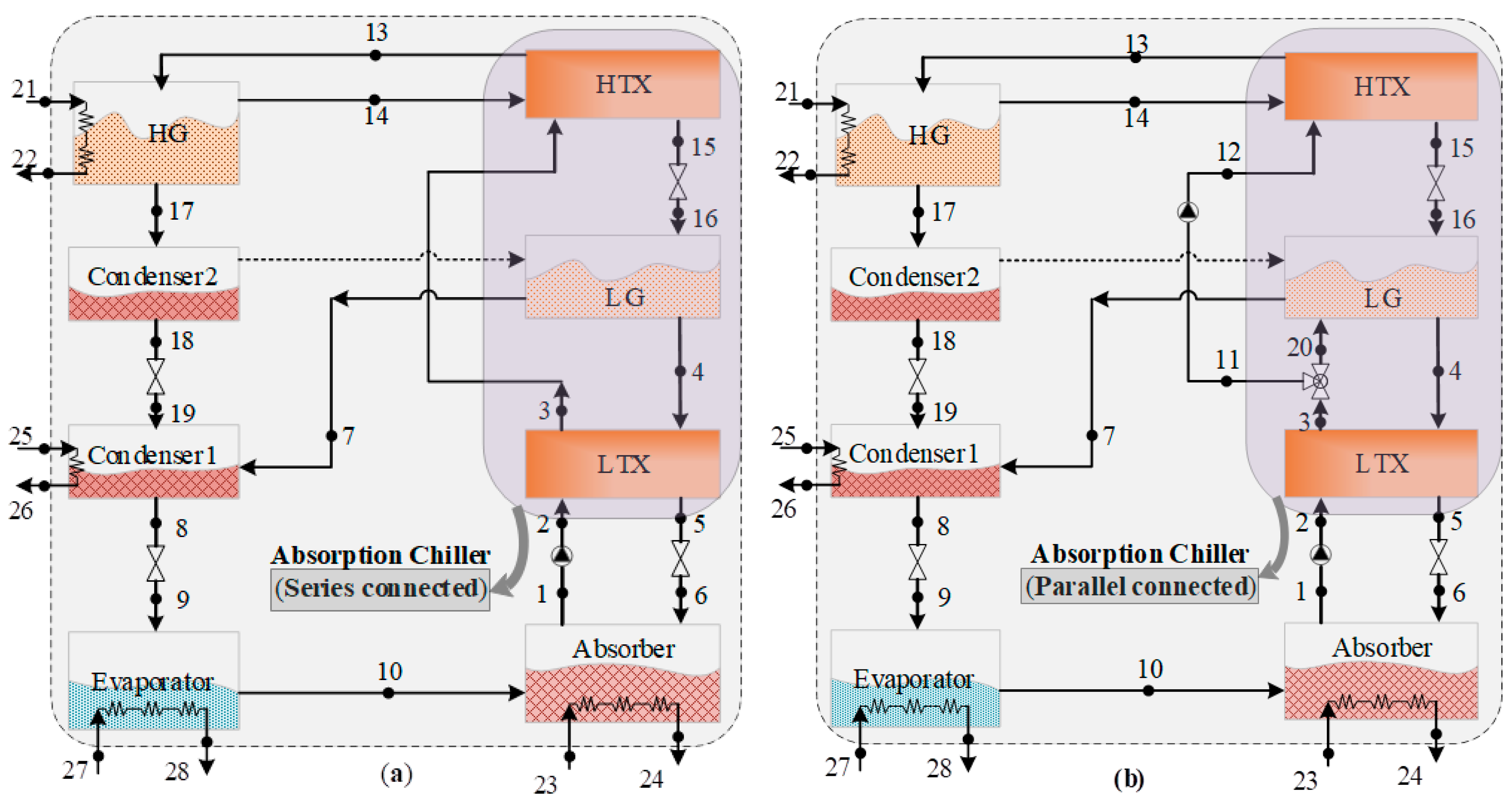
Figure 1. Energy flows in the absorption chillers (a) Series connected chiller, (b) Parallel connected chiller) (HG = High-pressure generator, LG = low-pressure generator, HTX = High-temperature heat exchanger, LTX = Low-temperature heat exchanger).
Energies 15 09105 g001
Figure 2. Heat-transfer area and exergy destruction ratio for two types of absorption chillers: (a) Heat-transfer area; (b) exergy destruction ratio.
Energies 15 09105 g002
Figure 3. Variations of heat-transfer areas with two types of absorption chillers as functions of cooling temperature and steam temperature (T21).
Energies 15 09105 g003
Figure 4. Variation of COP with two types of absorption chillers as function of cooling temperature and steam temperature (T21).
Energies 15 09105 g004
Figure 5. Variation of exergy efficiency with two types of absorption chillers as functions of cooling temperature and steam temperature (T21).
Energies 15 09105 g005
Figure 6. Variation in annual cost with two types of absorption chillers as functions of cooling temperature and steam temperature (T21).
Energies 15 09105 g006
Figure 7. Variation of heat-transfer areas with the two types of absorption chillers as function of chilled water temperature and steam temperature (T21).
Energies 15 09105 g007
Figure 8. Variation of COP with the two types of absorption chillers as a function of chilled water temperature and steam temperature (T21).
Energies 15 09105 g008
Figure 9. Variation of exergy efficiency with the two types of absorption chillers as function of chilled water temperature and steam temperature (T21).
Energies 15 09105 g009
Figure 10. Variation of the annual cost with the two types of absorption chillers as function of chilled water temperature and steam temperature (T21).
Energies 15 09105 g010
Figure 11. Variation of performance with parallel connected chiller as function of solution allocation ratio.
Energies 15 09105 g011
Table 1. Energy principles of components in two chiller types [33].
ItemSeries-Connected ChillerParallel-Connected Chiller
HG m 21 ( h 21 h 22 ) + m 13 h 13 = m 17 h 17 + m 14 h 14
LG m 16 h 16 + m 17 ( h 17 h 18 ) = m 7 h 7 + m 4 h 4 m 20 h 20 + m 16 h 16 + m 17 ( h 17 h 18 ) = m 7 h 7 + m 4 h 4
Condenser 1 m 19 h 19 + m 6 h 6 = m 7 h 7 + m 25 ( h 26 h 25 )
Evaporator m 9 h 9 = m 9 h 9 + m 19 ( h 28 h 27 )
Absorber m 10 h 10 + m 6 h 6 = m 1 h 1 + m 21 ( h 24 h 23 )
LTX m 2 ( h 3 h 2 ) = η L T X m 4 ( h 4 h 5 )
HTX η H T X m 14 ( h 14 h 15 ) = m 3 ( h 11 h 3 ) m 12 ( h 13 h 12 ) = η H T X m 14 ( h 14 h 15 )
m, h are the mass, enthalpy of each state, respectively. η is heat-exchange efficiency.
Table 2. Heat-transfer coefficient and heat efficiency for each component [31,33,34].
ItemValue
U, kW/(m2 K)HG, LG1.5
Absorber0.7
Evaporator1.5
Condenser2.5
LTX, HTX1.0
Heat efficiencyLTX, HTX ( η L T X , η H T X )0.5
Table 3. Initial investment cost for each component in AC [35].
ComponentInitial Investment Cost (Z)
HG, LG 1800 ( f HTA ) 0.8 + 24,915 Condenser 2119 ( f HTA ) 0.497
Evaporator 5900 ( f HTA ) 0.552 LTX, HTX 2674 ( f HTA ) 0.465
Absorber 9.976 ( f HTA ) 1.820
f is area conversion factor (10.764 in this study).
Table 4. Initial conditions of simulation for absorption chiller [37].
ItemWorking FluidValue
Cooling capacity of absorption chiller 400 kW
Inlet/outlet temperature of steam (T21)Solar steam170/160 °C
Inlet/outlet cooling temperature (T23, T25)Water25/34 °C
Inlet/outlet temperature of chilled water (T27)Water12/7 °C
Table 5. Heat capacities and relative errors of components.
Reference StudyThis StudyRelative Error, %
LG2252230.9
HG3483441.1
LTX1511435.3
HTX1461376.2
Absorber6035823.5
Condenser4324201.9
Table 6. Main simulation results of the two AC types (cooling capacity 400 kW).
ItemsSeries Connected ACParallel Connected AC
Solution allocation ratio-0.54
Total heat-transfer area228.64 m2237.59 m2
COP1.251.30
Exergy efficiency23.49%24.42%
Total annual cost455,428$541,939$
Table 7. External parameters in Section 4.2.
SectionSection 4.2.1Section 4.2.2Section 4.2.3
Solar steam temperature (T21), °C114–19298–158150
Cooling water temperature (T23, T25), °C25–352525
Chilled water temperature (T27), °C1210–1812
Solution allocation ratio (D)0.540.54025–1.0
Publisher’s Note: MDPI stays neutral with regard to jurisdictional claims in published maps and institutional affiliations.