Article

Modeling and Experimental Analysis of Overvoltage and Inrush Current Characteristics of the Electric Rail Traction Power Supply System

1
School of Electrical Engineering, Beijing Jiaotong University, No. 3 Shangyuancun in Haidian District, Beijing 100044, China
2
Shuohuang Railway Development Co., Ltd. of National Energy, Cangzhou 062350, China
*
Author to whom correspondence should be addressed.
Energies 2022, 15(24), 9308; https://doi.org/10.3390/en15249308
Submission received: 18 November 2022 / Revised: 2 December 2022 / Accepted: 6 December 2022 / Published: 8 December 2022
(This article belongs to the Special Issue Studies in the Energy Efficiency and Power Supply for Railway Systems)

Abstract

:
High-speed EMUs (electric multiple-units) frequently pass through the phase-separation zone during operation. Overvoltage generated during the operation of the vehicle-mounted circuit breaker has a long duration and high waveform steepness, which accelerates the service life of the vehicle-mounted equipment and is likely to cause insulation failures. For the above-mentioned problems, the operating overvoltage characteristics of high-speed EMU were obtained by traction substation-catenary-EMUs system (SCES) analysis and experiments, thus deriving the influences of the closed phase angle and the residual magnetism of the vehicle-mounted transformer on operating overvoltage. The results showed that the voltage phase of the catenary significantly affected the operating overvoltage, and the closed switching overvoltage was small at 0–40°, 140–210° and 320–350°. The voltage on the primary side of the vehicle-mounted transformer was 60.78 kV, with the transient impact of high-frequency oscillation overvoltage of 22.71 kV, and an initial period of oscillation of 0.01 ms. Then, the period became longer, and it took 0.5 ms for the high-frequency oscillation from attenuation to disappearance. Finally, a scheme of series reactance suppression devices was proposed to protect vehicle-mounted voltage transformers. This work is to provide data support for the insulation design and system protection of a traction power supply system.

1. Introduction

During the operation of the traction power supply network system, frequent overvoltage occurs due to the high speed of the EMUs, the short power supply interval, and frequently closed and opened on-board circuit breakers. For example, the closing and opening intervals are 5 min for a 25-km supply arm when the train is running at 300 km/h. Frequent overvoltage acts on high-voltage equipment, which can cause operation accidents with arrester action, inter-turn insulation breakdown of inductive devices, discharge between electrodes, and flashover along the surface. Recently, the frequent occurrence of insulation accidents due to overvoltage has attracted attention [1].
The vehicle-mounted main circuit breaker of the high-speed EMU adopts a high-voltage vacuum circuit breaker (VCB). Vacuum is used as an arc extinguishing and insulating media to cut off the power of the traction power supply system and prevent current overload in the system circuit and short troubles in time. When the high-speed EMUs pass through the neutral zone of the power supply section, the circuit breaker opens and closes. Before the EMU travels to the neutral zone, the vehicle-mounted load (motor part) is locked first, and the transformer runs with no load. After the circuit breaker opens the no-load transformer, the EMU enters the neutral zone. When the EMU enters the next power supply section, the circuit breaker is closed with the no-load transformer. After that, the vehicle-mounted load is unlocked and the power supply resumes. The operating overvoltage is usually generated at the moment of opening and closing of the circuit breaker [2]. Meanwhile, inrush currents are generated, which affects the insulation of EMU equipment and harms winding equipment. In severe cases, serious accidents occur by affecting the contact network and the tripping and misoperation of the traction substation. Therefore, it is urgent to study the operating overvoltage characteristics of EMU circuit breakers.
Given the overvoltage and inrush current problems of the power supply system, the main focus is on the mechanism of operating overvoltage, model and simulation methods, test methods, and suppression techniques. In terms of operating overvoltage generation mechanism, N. Alatawneh and I. Lafaia et al. studied the influence of line cable parameters on the frequency and time domain characteristics of system overvoltage. Long cables are the key factor affecting the high-frequency characteristics of overvoltage [3,4,5]. A. Theocharis and M. Popov believed that line distributed capacitance becomes an important factor affecting the transient process of overvoltage [6]. Erik K. Saathoff obtained the effect of the closed phase angle on overvoltage and inrush current [7]. Goertz et al. obtained the influence law of the capacitance-effect voltage polarity, peak value, and overvoltage wavefront time of power cables, proposing the most critical factors for the configuration of the cable in the HVDC system [8,9]. Yang et al. from Xi’an Jiaotong University studied the characteristics of inrush currents in the process of closing capacitive equipment. The ablation of the switch contact surface is the key factor causing the excessive inrush time and the increased number of heavy breakdowns [10,11]. A. Khamlichi et al. studied the key parameters affecting the operating overvoltage and determined the GIS structure and cable connection grounding system to reduce the voltage by reducing the length of the ground wire [12,13,14].
In terms of model calculation and simulation, Robert Ferdinand et al. believed that the residual magnetism in the transformer is a key factor affecting the overvoltage and inrush current of the system. The iron core is demagnetized through the swing circuit or pre-excitation current, which reduces overvoltage and inrush current [15,16,17,18,19]. Kuczek et al. established a no-load transformer model to analyze the overvoltage transient during the closing of a three-phase no-load transformer by a vacuum circuit breaker, proposing the feasibility of using an LC circuit to suppress overvoltage [20], and Ahmad M et al. analyzed the transient electromagnetic force in the transformer [21,22]. To study the voltage and current transients caused by vacuum-circuit breaker switching surges, Refs. [23,24] used ATP-EMTP software to calculate and model a wide-frequency system configuration composed of circuit breakers, cables, transformers, and arresters. Berger et al. studied the high-energy switch shock transient fluctuations of fast DC vehicles. Simulations are used to evaluate the sensitivity of vehicle-system parameters, with the applicability of the vehicle model verified [25].
To find the influence factors of the inrush-current and restrain method, Refs. [26,27,28] have proposed simplified methods for initial surge and peak surge amplitudes in electrical systems in terms of testing and overvoltage and inrush-current suppression methods. A vacuum circuit breaker suitable for medium voltage systems is designed to analyze the transient voltage and current waveforms occurring when the circuit breaker closes the capacitor circuit with test applications [29]. Refs. [30,31,32,33,34] theoretically analyzed operating overvoltage when the circuit breaker closed a load of different nature, proposing the use of RC resistance-capacitance absorber, MOA, and other protective measures to suppress operating overvoltage. Ref. [35] proposed a soft-start method using the slight damping response of the automatic voltage regulator AVR to affect the magnetizing inrush current of the transformer. Ref. [36] eliminated the surge current of the transformer by controlling the switch. Ref. [37] adopted an interpolation resistance method, which used the grounding resistance connected to the neutral point of the transformer and the delayed energization of each phase of the transformer to suppress the magnetizing inrush current. Virtual air-gap technology was proposed in Ref. [38], using the controllable parameters of equivalent thickness to cooperate with the transformer magnetic circuit to suppress the transformer magnetizing inrush current. The above research provides theoretical support and a method basis for the overvoltage and inrush current of the electrical structure of the traction-power supply system.
In the electric railway power supply structure, the power supply network has a power supply interval and a neutral zone the lengths of which are close to 30 km and 200 m, respectively. The distribution of capacitance and inductance parameters is quite different. The load of the traction power supply network system is the EMU, and the electrical parameters are complicated. Simulations and experimental research work is complex for the operating overvoltage characteristics of SCES, so the traditional research conclusions have some limitations.
This work studied the operating overvoltage of the traction power supply network system. The model research and experimental analysis were used to obtain the operating overvoltage characteristics and to explore the influence of the closing phase angle and the residual magnetism of the vehicle-mounted transformer on operating overvoltage. The work is to provide data support for the insulation design and system protection of the traction power supply system.

2. Transient Process and Model of SCES of High-Speed Rail Ways

2.1. Model Description of the Overvoltage of SCES

The overvoltage model of SCES is to analyze the mechanism of the overvoltage generation process, consisting of substations, catenaries, and EMU parameters. The simplified equivalent circuit model of the centralized parameters of SCES is shown in Figure 1, and the operation voltage can be expressed as Equation (1).
U S = U m sin ω t + φ
where US is the power supply voltage of the traction substation; RS and LS are the total equivalent resistance of the traction substation and catenary wire, respectively, Ω; inductance, H; LT is the vehicle-mounted transformer excitation inductance, H; CT the vehicle-mounted transformer winding and its stray capacitance to ground, F; K1 the vehicle-mounted circuit breaker.
The induced current has no sudden change; therefore, the LT branch of the vehicle-mounted transformer’s magnetic inductance is equivalent to an open circuit and is not calculated when the vehicle-mounted circuit breaker is closed. The system power supply supplies power to the no-load, vehicle-mounted transformer to charge its winding and ground stray capacitance when circuit breaker K1 is closed. The equivalent capacitance value is small, and the conversion of energy produces high-frequency oscillation in the loop. In Figure 1, the circuit equation of K1 at the moment of closing is as Equation (2) [17].
L S C T d 2 u C T d t 2 + R S C T d u C T d t + u C T = u S
when t = t0, the initial phase angle of closing is 0°, and the system power supply voltage is 27.5 kV with single phase.
U S = U m sin ω 0 t 0
In the equation, ω0 is the high-frequency oscillation frequency of the system when t = t0.
ω 0 = 1 / L S C T
Capacitor CT has no voltage initially. The voltage across the parallel circuit of inductance LT and capacitance CT is obtained after calculation, that is, the voltage on the primary side of the vehicle-mounted transformer can be expressed as Equation (5) [17,18,19].
u L = u C = U m 1 e R S 2 L S t × cos ω 0 t
When t = π/ω0, the maximum voltage on the primary side of the vehicle-mounted transformer is
U Lm = U Cm = U m 1 + e π R S 2 C T L S
When the vehicle-mounted circuit breaker is closing, the closing high-frequency oscillating voltage is divided into steady-state and transient-state components for calculation. The superposition of the two forms the instantaneous operating overvoltage on the primary side of the vehicle-mounted transformer. Equation (6) shows that the magnitude of the operating overvoltage is related to high-frequency oscillation frequency ω0, total equivalent resistance RS, and inductance LS of the traction substation and the catenary wire. The maximum operating overvoltage may be as high as two times the normal voltage of the system and then slowly attenuates over time. The rate of attenuation depends on total equivalent resistance RS and inductance LS of the traction substation and the catenary wire, the vehicle-mounted transformer winding, and stray capacitance CT.
For example, when the circuit breaker is closing, a magnetizing inrush current will be generated in the loop because the transformer’s magnetization curve is nonlinear and the magnetic flux cannot change suddenly. In addition, the excitation inrush current contains a large number of high-order harmonic components. When the current is about to cross the zero point, the arc of the circuit breakers fracture is extinguished at zero crossing. The cut-off effect of the vacuum circuit breaker leads to mutual conversion of the energy stored by the inductance and capacitance elements in the circuit. In circles, a fast transient overvoltage is formed in the loop, more harmful than the closing high-frequency oscillation overvoltage.

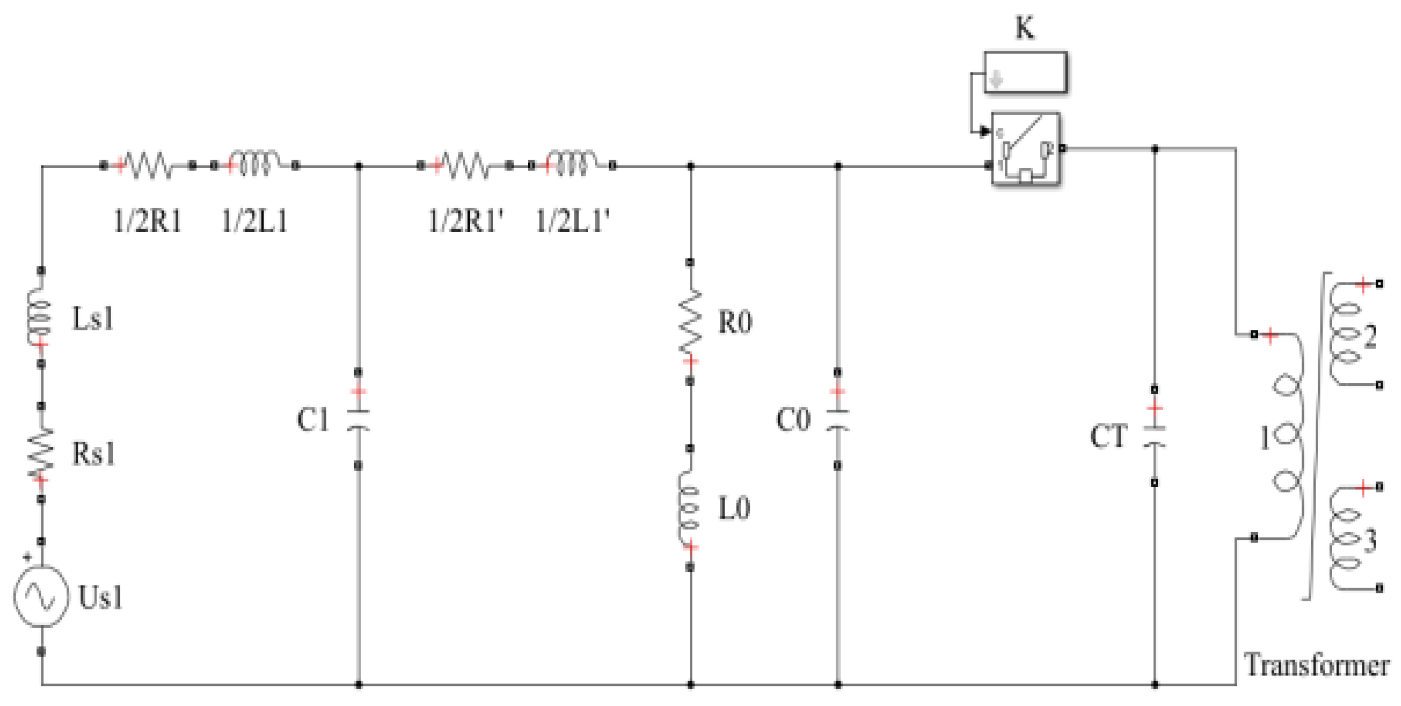
2.2. Simulation Model of SCES

The SCES model is mainly composed of the traction substation module, contact network module, phase division module, and EMU module for the parameters of the traction substation.

2.2.1. Main Technical Parameters of the System

Main technical parameters of the traction transformer and equivalent model are shown in Table 1 and Figure 2; the input voltage of the traction transformer is 110 kV and the output is 27.5 kV.
For the effective value of the rated voltage on the secondary side of the traction transformer, UN = 27.5 kV; the maximum voltage value on the secondary side of the traction transformer is as follows.
U max = 2 U N = 38.89   kV
The equivalent resistance of the traction transformer is:
R S = P K U N 2 1000 S N 2
where Pk is the short-circuit loss of the traction transformer; SN the rated capacity of the traction transformer.
The values in Table 1 are substituted into Equation (8) to obtain Rs = 0.545 Ω.
Equivalent inductance of the traction transformer can be expressed as Equation (9) [21,22,23]:
L S = X S 2 π f = U K % × U N 2 100 S N 2 π f
where f is the rated frequency of the system, f = 50 Hz; Uk% the percentage of the short-circuit voltage of the traction transformer. The values are substituted into Equation (9) to obtain Ls = 4.046 × 10⁻³ H.

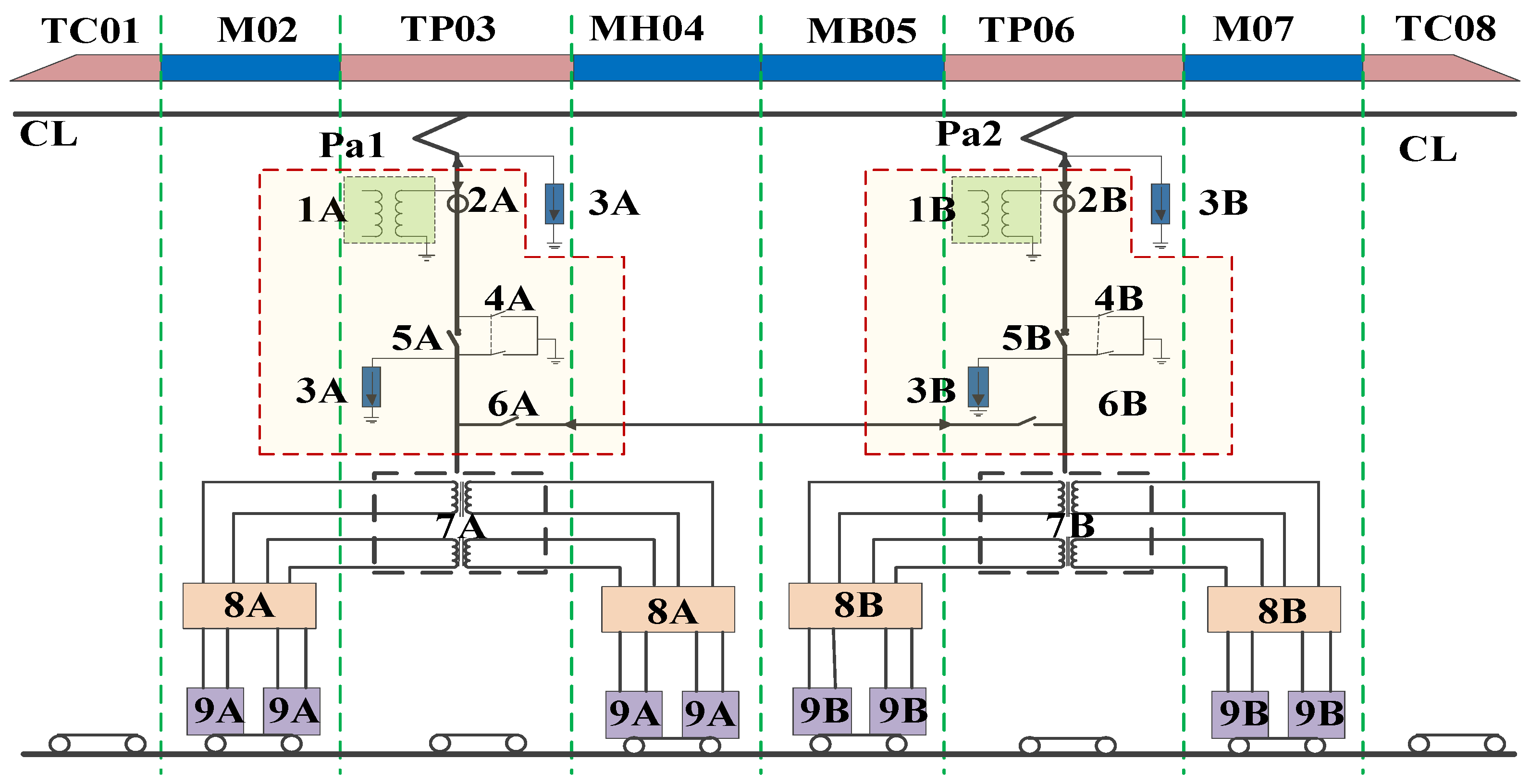
2.2.2. Catenary Module

The catenary module is mainly composed of the catenary equivalent resistance, inductance, and catenary equivalent capacitance to the ground, as shown in Figure 3.
Equivalent resistance of the catenary:
R 1 = ρ × l 1
where ρ is the resistivity of the catenary wire, and ρ = 0.179 Ω/km; l1 is the distance of the catenary wire from the traction substation to the electric phase separation, and l1 = 25 km. The values are substituted into Equation (10) to obtain R1 = 4.475 Ω. Equivalent inductance of the catenary
L 1 = X L 1 × l 1 2 π ω = 0 . 1445 lg D r eq + 0.0157 2 × l 1 2 π ω
where ω is the rated angular frequency of the system, ω = 100 π; D is the distance between catenaries in the complex-line section, and D = 4000 mm; req is the equivalent radius of the neutral line and the load-bearing cable, and req = 0.09487 m. Equivalent capacitance of the catenary to ground
C 1 = C 1 × C 1 C 1 + C 1
C 1 = C 1 = q U × l 1 = q q 2 π ε 0 ln 2 h r eq × l 1 = 2 π ε 0 × l 1 ln 2 h r eq
where C′ 1 is the equivalent ground capacitance of the contact line; C″ 1 the equivalent ground capacitance of the load-bearing cable; ε0 is the vacuum dielectric constant, ε0 = 8.85 × 10⁻¹² F/m; h is the average height of the catenary to the ground, and h = 6 m. The values are substituted into Equation (13) to obtain C1 = 1.438 × 10⁻⁷ F.

2.2.3. Neutral-Zone Module

The neutral zone adopts the type-T equivalent circuit model, as shown in Figure 4. The catenary model formula and parameters are used to calculate the neutral-zone equivalent resistance, inductance, and capacitance to ground and the coupling capacitance between the neutral zone wire and catenary on both sides of the overlap [7].
(1) Equivalent resistance of the neutral zone:
R 2 = ρ × l 2
where ρ is the resistivity of the neutral zone wire, and ρ = 0.179 Ω/km; l2 is the length of the neutral zone wire, and l2 = 350 m.
The values are substituted into Equation (14) to obtain R2 = 0.06265 Ω;
(2) Equivalent inductance of the neutral zone:
L 2 = X L 2 × l 2 2 π ω = 0 . 1445 lg D 1 D 2 r eq + 0.0157 2 × l 2 2 π ω
where D1 is the distance between the catenary in the complex-line section, and D1 = 4 000 mm; D2 is the distance between the catenary and the neutral zone, D2 = 500 mm;
The values are substituted into the Equations (2)–(15) to obtain L2 = 2.0054 × 10⁻⁴ H.
(3) Equivalent capacitance of the neutral zone to the ground:
C 2 = C 2 × C 2 C 2 + C 2
C 2 = C 2 = q U × l 2 = q q 2 π ε 0 ln 2 h r eq × l 2 = 2 π ε 0 × l 2 ln 2 h r eq
The values are substituted into Equation (17) to obtain C2 = 2.013 × 10⁻⁹;
(4) Coupling capacitance between the neutral zone and catenary
C 12 = 2 π ε 0 1 ln 2 h r eq ln 1 ln 4 h 2 + D 2 2 r eq × l 3
where h′ is the hanging height of the catenary, and h′ = 1300 mm; l3 is the distance between the neutral area wire and catenary, and l3 = 150 m.
The values are substituted into Equation (18) to obtain C12 = 1.485 × 10⁻⁸ F.

2.2.4. EMU Model

Extensive research has been carried out in the early stage [22,23,24,25,26], and the model of traction substation and the overhead line system model are mature. The EMU parameters in Figure 5 are combined with the parameters of the Fuxing bullet train to analyze equivalent circuit modeling.
Before phasing the EMU, the AC-DC-AC system is locked and the vehicle-mounted transformer runs at no-load, so only the parameter modeling of the vehicle-mounted transformer is considered. The high-speed EMU model is mainly equivalent to the roof high-voltage system and the vehicle-mounted transformer, and the roof high-voltage system is equivalent to resistance, inductance, and capacitance to ground to study the characteristics of electrical transient during passing through the phase separation zone. The vehicle-mounted transformer is equivalent to a saturation transformer due to the existence of residual magnetism.
(1) For the resistance of the voltage transformer (model TBY1-25), R0 = 3000 Ω;
(2) For the inductance of the voltage transformer in a non-saturated state,
L 0 = U 2 2 π f Q
where U is the primary voltage of the voltage transformer, and U = 25,000 V with a transformation ratio of 25,000/100 V; Q is the rated capacity of the voltage transformer, and Q = 20 VA. The values are substituted into Equation (19) to obtain L0 = 99,472 H;
(3) For the equivalent capacitance to ground between the roof high-voltage lead and the pantograph,
C 0 = C γ + C S
where Cγ is the equivalent capacitance of the roof high-voltage lead to the ground; Cs the equivalent capacitance of the pantograph to the ground.
C γ = 2 π ε 0 l 0 ln 2 h 0 r eq 0
C S = ε 0 S d = ε 0 S 1 d 1 + ε 0 S 2 d 2 + ε 0 S 3 d 3
where ε0 is the vacuum dielectric constant, and ε0 = 8.85 × 10⁻¹² F/m; h0 is the distance from the high-voltage lead to the roof, and h0 = 0.5 m; l0 is the length of the high-voltage lead, and l0 = 14.55 m; req0 is the high-voltage lead radius, and req0 = 17.5 mm; S1 is the ground area of the pantograph head, and S1 = 1.13 m2; d1 is the distance from the pantograph head to the roof, and d1 = 2 m; S2 is the ground area of the pantograph frame, S2 = 1.222 m2; d2 is the distance from the pantograph frame to the roof, and d2 = 1.5 m; S3 is the area of the pantograph base, and S3 = 0.846 m2; d3 is the distance from the pantograph base to the roof, and d3 = 0.32. The values are substituted into Equation (20) to obtain C0 = 2.3561 × 10⁻¹⁰ F.
Figure 6 shows the transformer model obtained by the electrical parameters of the main circuit of the EMU.
The distributed capacitance is connected to the line outlet in parallel according to a line capacitance of 0.1 μF. Figure 7 shows the closing and opening process model of the circuit breaker combined with the analysis of the circuit module, where Us1 is the operation voltage, Rs1 and Ls1 is the parameter of transformer in the traction substation, 1/2R1, 1/2L1, C1, 1/2R1and 1/2L1 are the parameter of the overhead line system, R0, L0 C0 is the equivalent parameter of the voltage transformer on the EMUs roof. CT is the capacitance of the EMUs roof.

3. Simulation Analysis of Operating Overvoltage and Inrush Current of SCES

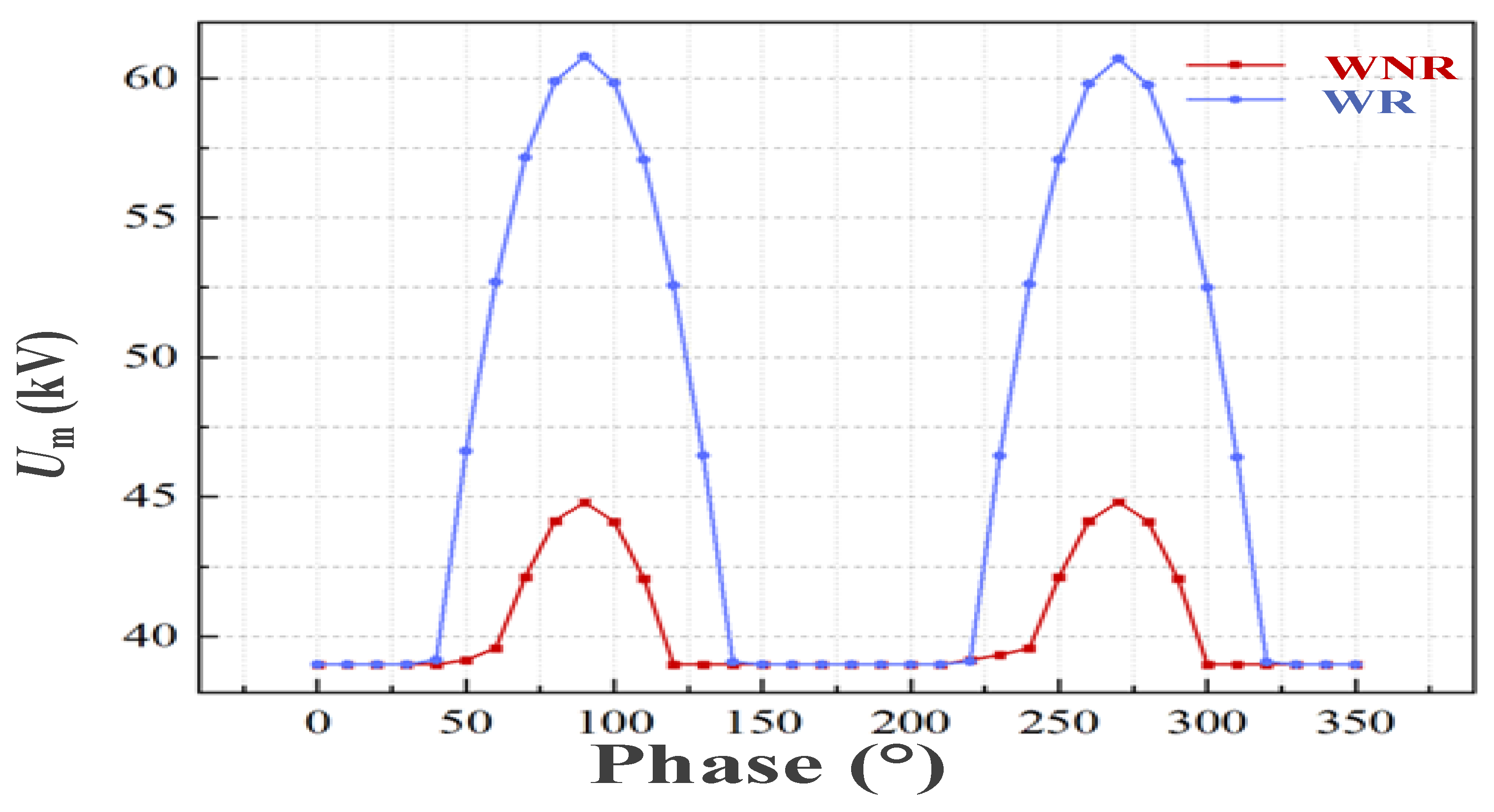
3.1. Overvoltage Characteristics

Operating overvoltage generates in the operating process of the vehicle-mounted circuit breaker when the bullet train enters and exits the phase separation zone. When entering the power supply section, the EMU is closed under the no-load condition of the transformer. The resulting operating overvoltage mainly includes closing high-frequency oscillation overvoltage, electromagnetic resonance overvoltage, and fast transient overvoltage. When the no-load transformer is switched on, no current flows in the no-load transformer, and there is no stored energy in the magnetizing inductance, winding, and stray capacitance to the ground. At the moment the circuit breaker is closed, the system power supply supplies power to the equivalent inductance and capacitance, and energy conversion occurs. A high-frequency oscillation occurs, and then an overvoltage of the closing operation appears. The circuit-breaker control parameter k in the vehicle network model is adjusted to control the closing phase angle of the circuit breaker, thus obtaining the 0 phase time of the power supply voltage. The voltage waveforms after the breaker are broken, as shown as Figure 8.
There is an oscillation process in the closing process of the circuit breaker, with an oscillation frequency of approximately 0.3 MHz. Based on the remanence characteristics of the vehicle-mounted transformer, when the remanence of the transformer is 0.7 pu., the amplitude of the overvoltage generated during the closing process of the circuit breaker is significantly increased compared with the case of no remanence, as shown in Figure 9.
The actual overvoltage of SCES is limited, considering the suppression effect of the arrester on the overvoltage.

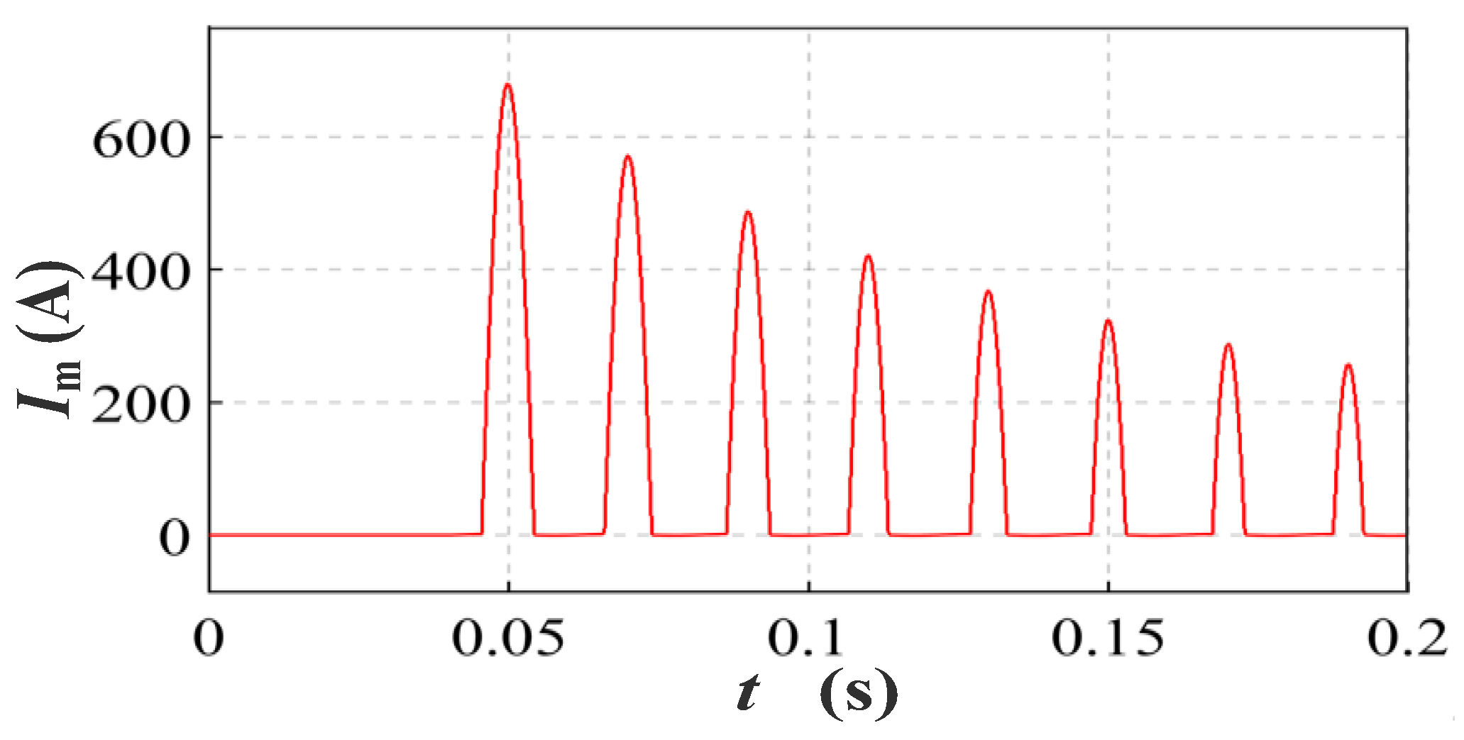
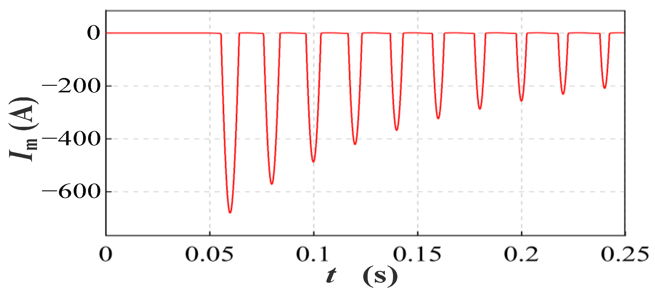
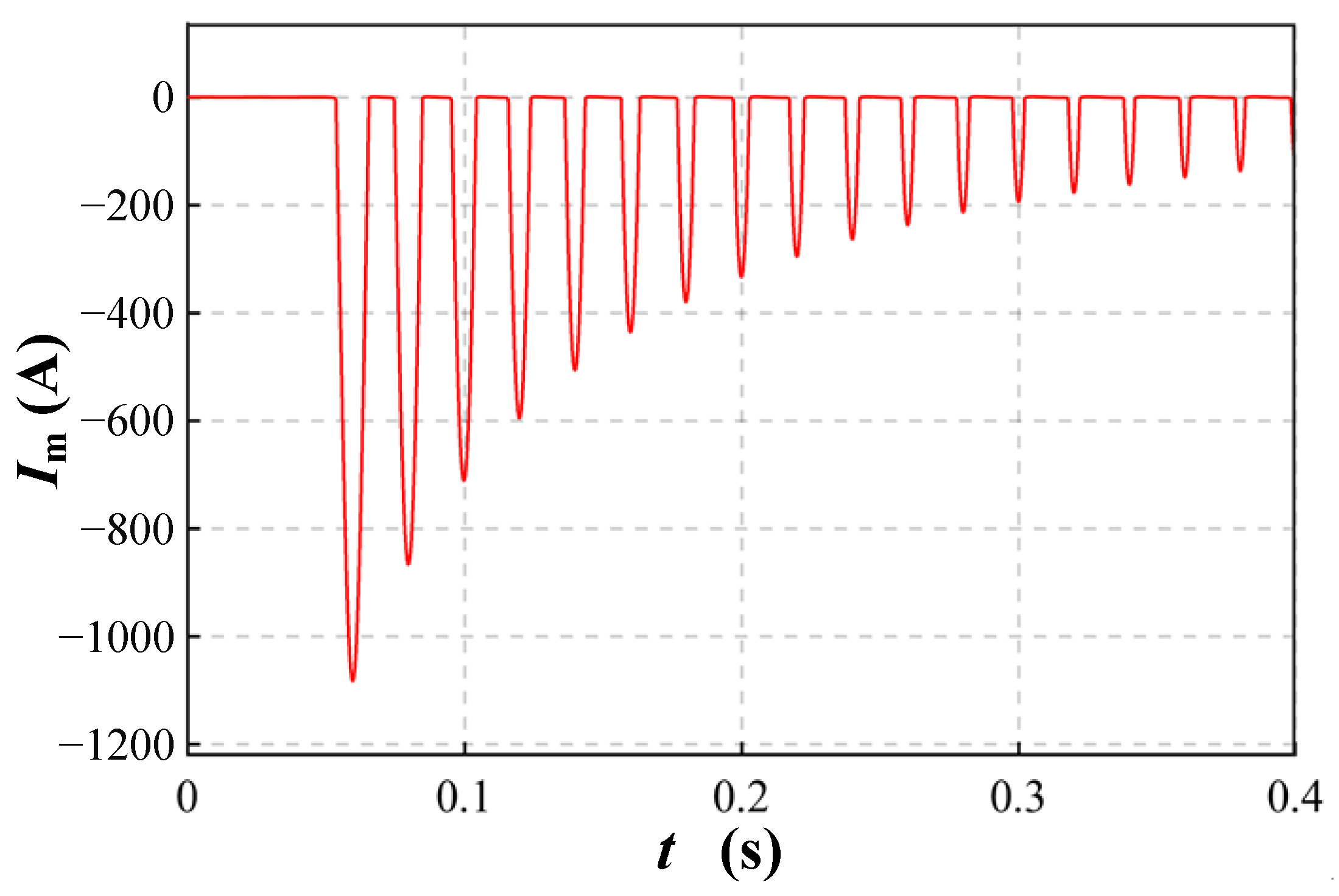
3.2. Inrush Current Characteristics of SCES

The closing excitation inrush current of the vehicle-mounted circuit breaker of high-speed EMUs has a great relationship with the remanence polarity and size of the vehicle-mounted transformer’s iron core. Figure 10 and Figure 11 show the excitation inrush current on the primary side of the transformer with the circuit breaker closing at 0° and 180°.
After two cycles of the circuit breaker closing time, the positive polarity remanence of the circuit breaker closing at 0° is 0.7 pu. by taking the transformer remanence of 0.7 pu. as an example. The inrush current waveforms is shown in Figure 12 and Figure 13.

4. Operational Overvoltage Test of SCES

4.1. Test System

The experiment study of overvoltage characteristics of SCES were carried out in the EMU maintenance station. The test power supply and catenary were the same as the parameters used in the simulation. The 110 kV source was from the traction substation, which is 2.35 from the maintenance station. The test instrument and the parameters are shown in Table 2.
The operating overvoltage is obtained on both sides of the circuit breaker port, and Figure 14 shows the test wiring.
Testing connection diagram on field is shown in Figure 15.

4.2. Test Process

The test referred to Part 1: General Definitions and Test Requirements in High Voltage Test Technology, GB/T16927.1-2011 (IEC60060-1:2010 MOD). After the EMU raised the pantograph, the system’s operating overvoltage test included the test of closing and opening processes.

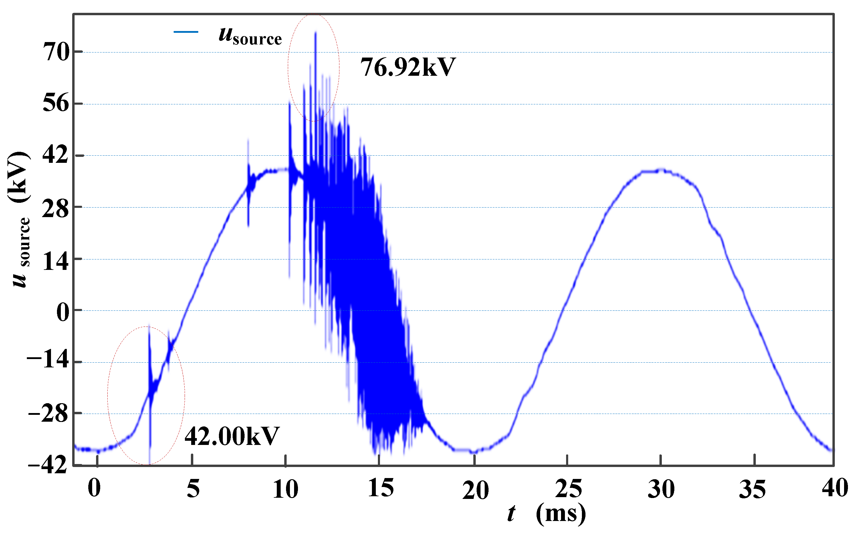
4.3. Overvoltage Characteristics

4.3.1. Closing Process

After raising the pantograph and contacting the bow net, a power frequency voltage appears on the power supply side of the circuit breaker (see Figure 16 Usource). After closing, the load side of the circuit breaker maintains the power frequency voltage, and the voltage waveform is shown as Uload in Figure 16.
The circuit breaker has obvious overvoltage during operation. The overvoltage is larger near the peak value, and the overvoltage multiple is 2.0. Meanwhile, during closing at different phase angles, the overvoltage generated will be reduced (see Figure 17). When the closing angle is −65°, the circuit breaker is closed, and the overvoltage multiple is 1.1.
Figure 18 shows the relationship between the closed phase angle and the overvoltage amplitude. As the closed phase angle increases, the overvoltage amplitude increases. When the voltage peak is closed, the overvoltage amplitude is the highest.
The circuit breaker has an obvious restrike in the closing process as shown at points a, b, c and d in Figure 19 with randomness. Multiple reignitions occur in severe conditions.
The overvoltage has a higher frequency oscillation process, and the highest oscillation frequency exceeds 0.1 MHz (as shown in Figure 20).
Comparing the test and simulation results in Figure 18, the model analysis and the actual line test results are in good agreement.

4.3.2. Opening Process

Before and after the circuit breaker is opened, the power frequency voltage on the power supply side is maintained, and the voltage on the load side drops to zero. In this process, the voltage on the load side has arcing overvoltage, and the overvoltage on the power supply side is not obvious and is less affected by the opening phase angle (shown in Figure 21).
The duration of overvoltage on the load side in the opening process is related to the opening moment, and the duration of the overvoltage is short when it is close to 0 (see Figure 22).
When the vehicle-mounted circuit breaker is closed and opened, the AC-DC system of the high-speed train has been locked. The over-phase process is the closing and opening process of the vehicle-mounted, no-load transformer. The SCES model was established to analyze the influence of different closing and opening phase angles on the overvoltage amplitude characteristics, thus obtaining the overvoltage characteristics of the traction power supply system. Combined with the analysis of the contact surface characteristics, electric field, and pre-breakdown process of the circuit breaker, the heavy breakdown process of the circuit breaker can be obtained.

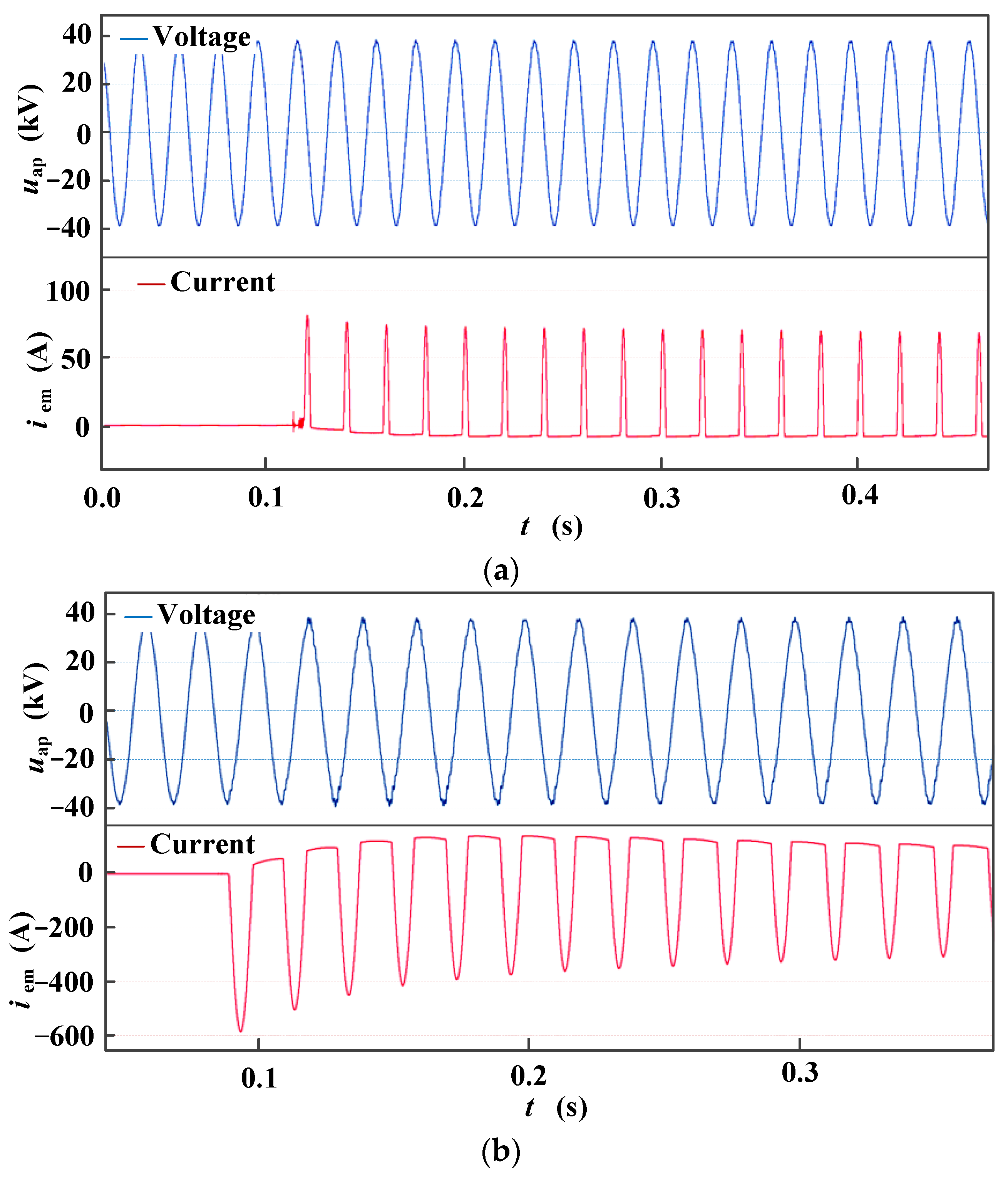
4.4. Inrush Current Characteristics

After testing, whenever the high-speed EMU passes through the phase division area, the vehicle-mounted circuit breaker will generate a magnetizing inrush current, and the magnitude and direction of currents are different. The pantograph network voltage and network current waveforms are selected at a certain four times from the test waveforms for analysis (see Figure 23a,b).
The magnetizing inrush current generated by the vehicle-mounted transformer when the circuit breaker is closed after the high-speed EMU passes through the phase-separating section is 623 A in the forward direction and 587 A in the reverse direction. The amplitude decays from the maximum value and stabilizes after 3 s. At this time, the grid voltage at the pantograph is approximately 41 kV, with a relatively stable waveform and less prominent overvoltage.
The typical magnetizing inrush current waveform is taken to enlarge (see Figure 24a,b). The magnetizing inrush current waveforms presenting randomness is a unilateral peak wave. Burrs corresponding to the voltage waveform appear, and the magnetizing inrush current affects the distortion of the grid voltage waveform.
The measured inrush current is 623 A in the forward direction and 587 A in the reverse direction, and the attenuation time is 3 ms. Equation (9) shows that the magnetic core flux of the vehicle-mounted transformer consists of steady-state and transient-state components. The amplitude of the former is constant, and the latter varies with the closed initial phase angle α0 and the magnitude and direction of the transformer’s remanence Φr. The vehicle-mounted circuit breaker is closed when the traction power supply system’s grid voltage phase α0 = 0°, and the grid voltage is zero-crossing. After the circuit breaker is closed for half a period, the magnetic core flux of the transformer is maximum. The transient-state component changes at any time. Once the magnetic core flux in the vehicle-mounted transformer exceeds the saturation magnetic flux of the iron core, a magnetizing inrush current appears in the loop. If the iron core saturation is deep, the magnetizing inrush current in the transient state can be 6–8 times the rated operating current in the steady state.
When the vehicle-mounted transformer is saturated in the forward direction, the circuit breaker closes at the initial phase angle (α0 = 0°) with the maximum magnetizing inrush current in the forward direction. When the vehicle-mounted transformer is reversely saturated, the circuit breaker closes at the initial phase angle (α0 = 180°) with the maximum magnetizing inrush current in the reverse direction.

5. Discussion

The SCES model consists of substations, catenaries, and EMUs. The phase separation of the EMU is the process of cutting off the EMU circuit breaker and switching off the no-load transformer. A large overvoltage at the transformer outlet exists due to the conversion of electromagnetic energy. Comparing the overvoltage transient-state process of the circuit-breaker operation in Figure 8 and Figure 18, the model calculation results and the test results are in good agreement. The system overvoltage is affected by the closed phase angle, and the amplitude increases with the increased closed phase angle.
During the test, a heavy breakdown can be found through voltage test waveforms (see Figure 25). The published literature already has a more thorough analysis of the phenomenon and characteristics of heavy breakdown. The number and amplitude of heavy breakdowns are related to the ablation position and ablation depth of the contact surface (see Figure 25a). When the circuit breaker is disassembled, the contacts of the circuit breaker have obvious ablation and aging. Compared with Ref. [2], contact ablation is an important cause of the heavy breakdown in the closing process of the circuit breaker.
Figure 25b shows that the surface ablation causes the heavy breakdown of the circuit breaker and overvoltage. Given the ablation of the circuit breaker, measures should be taken to monitor the operating conditions of the vacuum circuit breaker.

6. Conclusions

This work studied the overvoltage of traction power supply in SCES. Experiments, theories, and simulations were used to obtain the waveform characteristics of the operating wave voltage, the closing and opening phase angles, and other influence rules on overvoltage. Additionally, a scheme for suppressing the overvoltage of SCES was proposed.
(1)
The SCES generated overvoltage during the closing and opening process of the vehicle-mounted circuit breaker had large overvoltage amplitude. When the switch was closed at a phase angle of 90°, the overvoltage multiple was maximum. The overvoltage obtained in the test was approximately 65 kV, which caused the vehicle-mounted lightning arrester to operate. Meanwhile, overvoltage was in the steep amplitude, approximately 1.35 MV/s;
(2)
Under operating overvoltage conditions, the SCES generated magnetizing inrush currents. The inrush current value could reach 623 A with an inrush current steepness of approximately 174 kA/s, which endangered the operation safety of the vehicle-mounted winding electrical equipment;
(3)
Meanwhile, the residual magnetic characteristics of the vehicle-mounted transformer significantly affected the overvoltage analysis of SCES. The SCES produced multiple breakdowns due to the insulation between the contact surface and the internal circuit breaker, which affected the effectiveness of phase-controlled closing.

Author Contributions

Conceptualization, J.S.; Investigation, J.S.; Writing—original draft, J.S., K.H., Y.F., J.L., S.Y. and Y.Z.; Writing—review & editing, J.S., K.H., Y.F., J.L., S.Y. and Y.Z. All authors have read and agreed to the published version of the manuscript.

Funding

This work was supported by Fundamental Research Funds for the Central Universities (2021JBM025), the National Natural Science Foundation of China (51907003) and Science and Technology Project of National Energy Group (SHTL-21-08).

Data Availability Statement

The data in the paper is availability and can be published by “energies”.

Acknowledgments

The authors would like to thank reviewers for their pertinent comments that helped to improve the quality of this paper.

Conflicts of Interest

The authors have no conflict whither in the research field or to publish the paper on “energies”.

References

  1. Sun, J.; Ding, F.; Lv, Y.; Ren, J.; Song, S.; Li, T.; Zhi, Q.; Guo, C. Leakage current characteristics and ageing assessment technology of roof arrester under ultra harmonics overvoltage. High Volt. 2021, 7, 346–356. [Google Scholar] [CrossRef]
  2. IEC 60071-1 IEC; Insulation Co-Ordination Part 1: Definitions, Principles and Rules. IEC: Geneva, Switzerland, 2011.
  3. Alatawneh, N. Effects of cable insulations’ physical and geometrical parameters on sheath transients and insulation losses. Electr. Power Energy Syst. 2019, 110, 95–106. [Google Scholar] [CrossRef]
  4. Lafaia, I.; Mahseredjian, J.; Ametani, A.; de Barros, M.T.C.; Kocar, I.; Fillion, Y. Frequency and time domain responses of cross-bonded cables. IEEE Trans. Power Deliv. 2017, 33, 640–648. [Google Scholar] [CrossRef]
  5. Hosseini, S.H.; Baravati, P.R. New high frequency multi-conductor transmission line detailed model of transformer winding for PD study. IEEE Trans. Dielectr. Electr. Insul. 2017, 24, 316–323. [Google Scholar] [CrossRef]
  6. Theocharis, A.; Popov, M.; Seibold, R.; Voss, S.; Eiselt, M. Analysis of Switching Effects of Vacuum Circuit Breaker on Dry-Type Foil-Winding Transformers Validated by Experiments. IEEE Trans. Power Deliv. 2014, 30, 351–359. [Google Scholar] [CrossRef]
  7. Han, Z.; Liu, S.; Gao, S. An automatic system for China high-speed multiple unit train running through neutral section with electric load. In Proceedings of the Asia-Pacific Power and Energy Engineering Conference, Chengdu, China, 28–31 March 2010; pp. 1–3. [Google Scholar]
  8. Goertz, M.; Wenig, S.; Beckler, S.; Hirsching, C.; Suriyah, M.; Leibfried, T. Analysis of Cable Overvoltages in Symmetrical Monopolar and Rigid Bipolar HVDC Configuration. IEEE Trans. Power Deliv. 2019, 35, 2097–2107. [Google Scholar] [CrossRef]
  9. Yu, Y.; Li, G.; Geng, Y.; Wang, J.; Liu, Z. Prestrike Inrush Current Arc Behaviors in Vacuum Interrupters Subjected to a Transverse Magnetic Field and an Axial Magnetic Field. IEEE Trans. Plasma Sci. 2018, 46, 3075–3082. [Google Scholar] [CrossRef]
  10. Yang, H.; Geng, Y.; Liu, Z.; Zhang, Y.; Wang, J. Capacitive Switching of Vacuum Interrupters and Inrush Currents. IEEE Trans. Dielectr. Electr. Insul. 2014, 21, 159–170. [Google Scholar] [CrossRef]
  11. Budzisz, J.; Pierz, P. Transient Current and Voltage Waveforms When Switching on a Capacitive Circuit with a Vacuum Circuit Breaker. In Proceedings of the 2018 Progress in Applied Electrical Engineering (PAEE), Koscielisko, Poland, 18–22 June 2018. [Google Scholar]
  12. Khamlichi, A.; Donoso, G.; Garnacho, F.; Denche, G.; Valero, A.; Álvarez, F. Improved Cable Connection to Mitigate Transient Enclosure Voltages in 220-kV Gas-Insulated Substations. IEEE Trans. Ind. Appl. 2015, 52, 562–569. [Google Scholar] [CrossRef]
  13. Szewczyk, M.; Piasecki, W.; Wroński, M.; Kutorasiński, K. New Concept for VFTO Attenuation in GIS with Modified Disconnector Contact System. IEEE Trans. Power Deliv. 2015, 30, 2138–2145. [Google Scholar] [CrossRef]
  14. Guan, Y.; Yue, G.; Chen, W.; Li, Z.; Liu, W. Experimental Research on Suppressing VFTO in GIS by Magnetic Rings. IEEE Trans. Power Deliv. 2013, 28, 2558–2565. [Google Scholar] [CrossRef]
  15. Ferdinand, R.; Monti, A. Export Transformer Switching Transient Mitigation in HVDC Connected Offshore Wind Farms. IEEE Trans. Power Deliv. 2019, 35, 37–46. [Google Scholar] [CrossRef]
  16. Ghafourian, S.M.; Arana, I.; Holboll, J.; Sorensen, T.; Popov, M.; Terzija, V. General Analysis of Vacuum Circuit Breaker Switching Overvoltages in Offshore Wind Farms. IEEE Trans. Power Deliv. 2016, 31, 2351–2359. [Google Scholar] [CrossRef]
  17. Cardelli, E.; Faba, A.; Tissi, F. Prediction and Control of Transformer Inrush Currents. IEEE Trans. Magn. 2015, 51, 8400304. [Google Scholar] [CrossRef]
  18. Elizondo, M.A.; Tuffner, F.K.; Schneider, K.P. Simulation of Inrush Dynamics for Unbalanced Distribution Systems Using Dynamic-Phasor Models. IEEE Trans. Power Syst. 2016, 32, 633–642. [Google Scholar] [CrossRef]
  19. Abdulahović, T.; Thiringer, T. Voltage stress in a transformer winding during very fast transients caused by breaker closing event. IEEE Trans. Power Deliv. 2014, 29, 1946–1954. [Google Scholar] [CrossRef]
  20. Kuczek, T.; Florkowski, M.; Piasecki, W. Transformer Switching with Vacuum Circuit Breaker: Case Study of PV Inverter LC Filters Impact on Transient Overvoltages. IEEE Trans. Power Deliv. 2016, 31, 44–49. [Google Scholar] [CrossRef]
  21. Moradnouri, A.; Vakilian, M.; Hekmati, A.; Fardmanesh, M. Multi-segment Winding Application for Axial Short Circuit Force Reduction under Tap Changer Operation in HTS Transformers. J. Supercond. Nov. Magn. 2019, 32, 3171–3182. [Google Scholar] [CrossRef]
  22. Moradnouri, A.; Vakilian, M.; Hekmati, A.; Fardmanesh, M. HTS transformers leakage flux and short circuit force mitigation through optimal design of auxiliary windings. Cryogenics 2020, 110, 103148. [Google Scholar] [CrossRef]
  23. Shipp, D.D.; Dionise, T.J.; Lorch, V.; MacFarlane, W.G. Vacuum circuit breaker transients during switching of an LMF transformer. IEEE Trans. Ind. Appl. 2012, 48, 37–44. [Google Scholar] [CrossRef]
  24. Zhang, L.; Wang, S.; Sun, L.; Mao, C.; Pu, L.; Zhang, Q. Prediction model of voltage–time characteristics for SF6 long gap under VFTO and lightning impulse voltage. IET Gener. Transm. Distrib. 2018, 12, 880–885. [Google Scholar] [CrossRef]
  25. Berger, M.; Grave, J.-P.M.; Lavertu, C.; Kocar, I.; Mahseredjian, J.; Ferrara, D. Modeling, Simulation, and Testing of Switching Surge Transients in Rapid Transit Vehicles DC Power Systems. IEEE Trans. Ind. Appl. 2017, 54, 822–831. [Google Scholar] [CrossRef]
  26. Yu, L. Quick Evaluation of Voltage Surge in Electrical Power Systems. IEEE Trans. Ind. Appl. 1995, 31, 379–383. [Google Scholar]
  27. Sun, J.; Sun, L.; Chen, W.; Li, Z.; Yan, X.; Xu, Y. Metal particle movement and distribution characteristics under AC voltage and ball-plane electrodes. High Volt. 2019, 4, 138–143. [Google Scholar] [CrossRef]
  28. Szewczyk, M.; Kutorasinski, K.; Wronski, M.; Florkowski, M. Full-Maxwell simulations of very fast transients in GIS: Case study to compare 3-D and 2-D-axisymmetric models of 1 100 kV test setup. IEEE Trans. Power Deliv. 2016, 32, 733–739. [Google Scholar] [CrossRef]
  29. Saathoff, E.K.; Green, D.H.; Agustin, R.A.; O’Connell, J.W.; Leeb, S.B. Inrush Current Measurement for Transient Space Characterization and Fault Detection. IEEE Trans. Instrum. Meas. 2021, 70, 3520410–3520419. [Google Scholar] [CrossRef]
  30. Cervantes, M.; Ametani, A.; Martin, C.; Kocar, I.; Montenegro, A.; Goldsworthy, D.; Tobin, T.; Mahseredjian, J.; Ramos, R.; Marti, J.R.; et al. Simulation of Switching Overvoltages and Validation with Field Tests. IEEE Trans. Power Deliv. 2018, 33, 2884–2893. [Google Scholar] [CrossRef]
  31. Yang, Q.; Chen, S.; Zeng, X.; Wei, G.; Liu, H.; Chen, T. Suppression Measures for Overvoltage Caused by Vacuum Circuit Breaker Switching Off 10-kV Shunt Reactor. IEEE Trans. Power Deliv. 2019, 35, 540–548. [Google Scholar] [CrossRef]
  32. Jacobson, D.A.N. Examples of ferromagnetic resonance in a high voltage power system. In Proceedings of the Power Engineering Society General Meeting, Toronto, ON, Canada, 13–17 July 2003; IEEE: Manhattan, NY, USA, 2003; pp. 37–40. [Google Scholar]
  33. Sun, J.; Song, S.; Zheng, J.; Li, Z.; Huo, J.; Wang, Y.; Xiao, P.; Akram, S.; Qin, D. Review on Surface Flashover Phenomena at DC Voltage in Vacuum and Compressed Gas. IEEE Trans. Dielectr. Electr. Insul. 2022, 29, 1–14. [Google Scholar] [CrossRef]
  34. Sun, J.; Lv, Y.; Ding, F.; Liu, J.; Zhi, Q.; Song, S.; Wen, H. A testing method with steep impact voltage inspecting the internal defects in EMU roof cable termination. IET Sci. Meas. Technol. 2022, 16, 149–159. [Google Scholar] [CrossRef]
  35. Smith, K.; Ran, L.; Leyman, B. Analysis of transformer inrush transients in offshore electrical systems. IEE Proc. Gener. Transm. Distrib. 1999, 146, 89–95. [Google Scholar] [CrossRef]
  36. Brunke, J.H.; Frohlich, K.J. Elimination of Transformer Inrush Currents by Controlled Switching, part I: Theoretical Considerations. IEEE Trans. Power Deliv. 2001, 16, 276–290. [Google Scholar] [CrossRef]
  37. Gray, E.; Uhrig, T. Voltage Brealkdon Testing of Relays in the 1000-V Range. IEEE Trans. Compon. Hybrids Manuf. Technol. 1980, 3, 442–448. [Google Scholar] [CrossRef]
  38. Gray, E.W.; Harrington, D.J. Surface Topography of Printed Wiring Boards and Its Effect on Flashover. IEEE Trans. Compon. Hybrids Manuf. Technol. 1982, 5, 142–146. [Google Scholar] [CrossRef]
Figure 1. Equivalent circuit of vehicle-mounted circuit breaker closing.
Energies 15 09308 g001
Figure 2. Equivalent model of the traction substation.
Energies 15 09308 g002
Figure 3. Equivalent model of the catenary.
Energies 15 09308 g003
Figure 4. Equivalent model of the neutral zone.
Energies 15 09308 g004
Figure 5. Equivalent model of the neutral zone (CL is contact wire, Pa1 is pantograph, 1A is voltage transformer, 2A is current transformer, 3A is arrester, 4A is earthing switch, 5A is breaker with operating voltage 25 kV and short-circuit current 25 kA, 6A is isolating switch, 7A is traction transformer, 8A is converter, 9A is traction motor, 1B–9B are the same devices as 1A–9A while they are spinning reserved).
Energies 15 09308 g005
Figure 6. Main circuit structure of the high-speed EMU.
Energies 15 09308 g006
Figure 7. Simulation model of closing and opening of the vehicle-mounted circuit breaker.
Energies 15 09308 g007
Figure 8. Overvoltage transient process.
Energies 15 09308 g008
Figure 9. Influence of residual magnetism on overvoltage (WR is “with residual magnetization”, WNR is “without residual magnetization”).
Energies 15 09308 g009
Figure 10. Magnetizing inrush current waveforms on the primary side of vehicle-mounted transformer closing at 0°.
Energies 15 09308 g010
Figure 11. Magnetizing inrush current waveforms on the primary side of vehicle-mounted transformer closing at 180°.
Energies 15 09308 g011
Figure 12. Magnetizing inrush current waveforms on the primary side of vehicle-mounted transformer closing at 0° (Φr = 0.7 pu).
Energies 15 09308 g012
Figure 13. Magnetizing inrush current waveform on the primary side of the vehicle-mounted transformer when closing at 180° (Φr = 0.7 pu).
Energies 15 09308 g013
Figure 14. Test circuit wiring (In the figure VD1 and VD2 is voltage divider, T is transformer with no-load).
Energies 15 09308 g014
Figure 15. Testing connection diagram on field.
Energies 15 09308 g015
Figure 16. Operating overvoltage in the closing process of the vehicle-mounted circuit breaker.
Energies 15 09308 g016
Figure 17. Operating overvoltage in the closing process when the phase angle is −65°.
Energies 15 09308 g017
Figure 18. Operational overvoltage test results.
Energies 15 09308 g018
Figure 19. Operating overvoltage in the closing process when the phase angle is −90°.
Energies 15 09308 g019
Figure 20. Oscillation process of overvoltage.
Energies 15 09308 g020
Figure 21. Overvoltage transient-state waveform when the vehicle-mounted circuit breaker is opened at the peak.
Energies 15 09308 g021
Figure 22. Transient-state waveforms of overvoltage when the vehicle-mounted circuit breaker is opened at the peak.
Energies 15 09308 g022
Figure 23. Network voltages and current waveforms at the pantograph when the breaker is closed. (a) Inrush current under the closing condition (in the forward direction). (b) Inrush current under the closing conditions (in the reverse direction).
Energies 15 09308 g023
Figure 24. Partially enlarged waveforms of the magnetizing inrush current. (a) Enlarged view of the closed inrush current (in the forward direction). (b) Enlarged view of the closed inrush current (in the reverse direction).
Energies 15 09308 g024
Figure 25. Mechanical and electrical damage on the contact surface of the vacuum circuit breaker. (a) Relationship between the contact surface damage and heavy breakdown [2]. (b) Ablation status of the vacuum circuit breaker contact of the EMU.
Energies 15 09308 g025
Table 1. Main technical parameters of the traction transformer.
Rated voltage (kV)Rated capacity (MVA)No-load current (%)
110/27.5502
Loss with no-load (kW)Short circuit loss (kW)Short circuit voltage (%)
251328.4
Table 2. List of Test Equipment.
DesignationQuantityRemark
Overvoltage recorder1Um100 kV, 1 MHz, 1%,
Capacitive voltage divider20–35 kV, 1 247.2/1, ±1%
Voltage probe4100 V/2 V, 1%
Publisher’s Note: MDPI stays neutral with regard to jurisdictional claims in published maps and institutional affiliations.

