Article

A Tortuosity Engineered Dual-Microporous Layer Electrode Including Graphene Aerogel Enabling Largely Improved Direct Methanol Fuel Cell Performance with High-Concentration Fuel

1
Institute for Energy Research, Jiangsu University, Zhenjiang 212013, China
2
Department of Chemical and Process Engineering, University of Surrey, Guildford GU2 7XH, UK
3
Faculty of Electrical Engineering, Mechanical Engineering and Naval Architecture, University of Split, 21000 Split, Croatia
*
Author to whom correspondence should be addressed.
Energies 2022, 15(24), 9388; https://doi.org/10.3390/en15249388
Submission received: 18 November 2022 / Revised: 29 November 2022 / Accepted: 8 December 2022 / Published: 12 December 2022
(This article belongs to the Special Issue Advances in Proton Exchange Membrane Fuel Cell)

Abstract

:
Methanol crossover is an important factor affecting the performance of direct methanol fuel cells (DMFCs). In this work, a novel membrane electrode assembly (MEA) is designed and prepared by adding a layer of graphene aerogel (GA) between the carbon powder microporous layer and the catalytic layer, which optimizes the methanol transport and improves the output performance of DMFC at high methanol concentrations. Compared to conventional carbon powder, the addition of GA increases the tortuosity of the anode in the through-plane direction; hence, methanol is diluted to a suitable concentration when it reaches the catalyst. The maximum power density of the novel MEA can reach 27.4 mW·cm−2 at a condition of 8 M methanol, which is 234% higher than that of the conventional electrode. The test results of electrochemical impedance spectroscopy (EIS) indicate that the addition of GA does not increase the internal resistance of the novel MEA and that the mass transfer resistance at high concentrations is significantly lower. The experimental results indicate that the output performance at high concentration can be significantly improved by adding a GA layer, and its practicability in portable devices can be improved. It also improves the stability of DMFC under long-term testing.

Graphical Abstract

1. Introduction

Due to their low space usage, simple construct design, high energy density, and high power density in low temperature operation, making them especially suitable for portable mobile devices, direct methanol fuel cells (DMFCs) have received much attention and research [1,2,3,4]. However, the poor anode reaction kinetics and the methanol crossover, where the methanol molecule crosses the polymer electrolyte membrane, causing mixing potential at the cathode, seriously affect the performance of DMFCs at high concentrations. Methanol crossover causes cathode mixed potential to reduce cell performance and cell efficiency [5,6,7]. The key to these issues is the MEA, the heart of the fuel cell.
In an MEA, the anode GDL is usually composed of backing layer (BL) and a microporous layer (MPL), which play a key role in the transfer of electrons and mass. The anode mass transfer, methanol crossover and cathode flooding are affected by the material and structure of MPL [8,9,10]. In addition to traditional conductive carbon powder, carbon nanotubes (CNTs), carbon nanofibers (CNFs) and other materials are also used in MPL [3,11,12,13,14,15]. For instance, Kim et al. [3] constructed an anode MPL with a mix of materials to successfully control methanol crossover. At the same time, it retains good electronic conductivity and gas transport. Yuan et al. [13] added mixed carbon nanotubes to the anode MPL to reduce the anode charge transfer resistance and the catalyst loss rate and achieve the purpose of improving the performance of DMFC. The permeation of anode methanol seriously affects the overall performance of the cell. The development of alternative membranes that can reduce methanol penetration is a major trend [16]. Li et al. [17] successfully synthesized a poly-based pore-filling membrane. The synthetic membrane showed a better choice of proton conductivity and methanol permeability than Nafion 117. Parthiban et al. [18] synthesized a particular nanoporous carbon-Nafion hybrid membrane with 50% less methanol crossover compared with the original Nafion membrane. Sun et al. [19] introduced a molecular sieve into the Nafion membrane, which resulted in a methanol diffusion about four times lower than the original Nafion membrane. These works mainly focus on the modification of the membrane in DMFC to seek to reduce the effect of methanol permeation; few studies have exploited the structural properties of the material itself to decrease anode methanol crossover.
The anode MPL provides transport channels for reactants and products and is an important pathway for electron transport. Therefore, the material of MPL must have the following characteristics: a uniform porous structure, good electrical conductivity and mechanical strength. Graphene aerogel (GA) is a 3D nanoporous material composed of graphene sheets that cross-link in space. Its unique structure greatly reduces the stacking problems of graphene sheets due to van der Waals forces and, at the same time, has the characteristics of low density, excellent electrical conductivity, high porosity and a high specific surface area. So far, with its specific physical structure and chemical properties, GA has been successfully used in many fields, such as supercapacitors, catalyst support and so on [20,21,22,23]. The application of GA in the field of FC is mainly in the field of catalyst support [24,25,26,27,28,29]. Gao et al. [25] prepared Pt nanocrystals on 3D structures constructed by graphene and MoS2 nanosheets. The multipurpose catalyst exhibits high durability and strong toxicity resistance in methanol oxidation. The 3D N-doped graphene aerogel e-capsulated Fe3C/C nanoparticles were researched by Yang et al. [26]. Due to the existence of mesoporous structure and Fe-N-C functionalities that afford catalytic sites, the conductivity and accessibility of active sites of the novel material are effectively promoted. Guo et al. [27] synthesized nitrogen-doped graphene aerogel microspheres as novel catalyst supports, and the mass catalytic activity and stability of this new type of support catalyst were greatly improved. Table 1 shows some applications of GA in DMFC in recent studies. However, although sufficient research has been conducted on catalyst support, few applications of graphene aerogel on DMFC MPLs have been reported.
In this work, a unique dual-microporous layer structure composed of graphene aerogels is proposed. The novel anode MPL is composed of an outer MPL of carbon powder (with PTFE as a binder) and an inner MPL of graphene aerogel (with Nafion as a binder). The unique three-dimensional porous structure of graphene aerogels plays the role of tortuosity engineering for the new MPL [32] and helps to optimize anode methanol transport at high concentrations and reduce methanol crossover during DMFC operation. The results show that the output performance of DMFC at high concentrations is greatly improved, ameliorating the negative effects of methanol crossover.

2. Experimental

2.1. Fabrication of GDL

In this work, two different anode MPLs were designed and assembled into two different MEAs. MEA-1 is the single microporous layer of MEA, with a 2 mg cm−2 loading of carbon powder (Vulcan XC-72) and PTFE (15 wt.%) deposited on the anode backing layer. The dual-microporous layer MEA is MEA-2. In a double-layer structure, the outer MPL with 1.5 mg cm−2 loading carbon powder (Vulcan XC-72) and 15% content PTFE deposited on carbon paper. Graphene aerogel with a 0.5 mg cm−2 loading and Nafion 30% content deposited on the outer MPL to form the inner MPL. The carbon powder (or GA) and PTFE (or Nafion) were added to isopropyl alcohol, the mixed solution was ultrasonicated for 2 h to obtain a uniformly dispersed solution, and the anode GDL was formed by direct spraying. The cathode diffusion layer is prepared in a similar way as the anode, with a 2 mg cm−2 loading of carbon powder. Hydrophobic treatment of carbon paper with 15% PTFE in both the cathode and anode as a backing layer.

2.2. Fabrication of MEA

Firstly, 60 wt.% PtRu/C and 40 wt.% Pt/C were mixed with DI (de-ionized) water, Nafion solutions and isopropyl alcohol and were perfectly dispersed in sonication as catalyst slurries. Secondly, the prepared catalyst slurry was sprayed on the GDL prepared in the previous step to form the anode and cathode. Then, the Nafion 212 membrane was placed between the obtained electrodes. The pretreatment of proton exchange membranes has been described elsewhere [33]. Both PtRu and Pt loadings are 2 mg cm−2 for the prepared MEA [34,35].

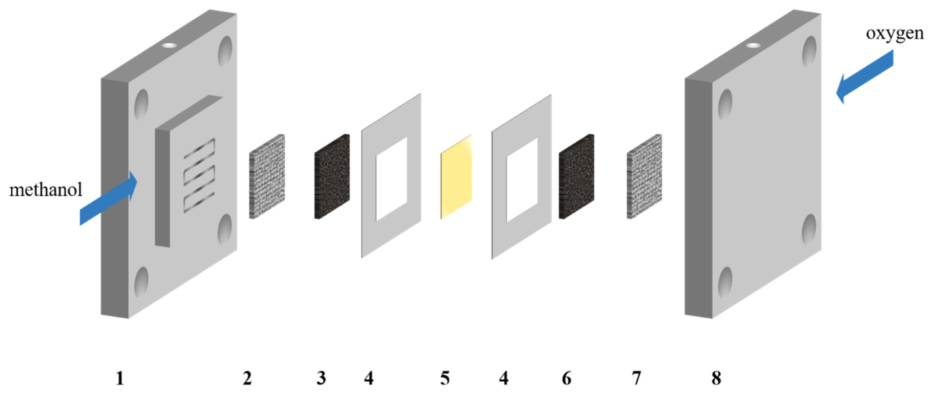
2.3. Single Cell Fixture

The MEA was sandwiched between two stainless steel clamps. Methanol was stored in a liquid tank and transported to the anode fixture side by a peristaltic pump (BT100-1F, longer). Oxygen was supplied to the cathode fixture side, and the flow rate was controlled by a rotameter. A heating rod heated the cell while it was running, and a thermocouple measured the cell operating temperature. Figure 1 shows the assembly diagram of DMFC.

2.4. Electrochemical Characterization

A system consisting of an Arbin BT 2000 (Arbin Instrument Inc., College Station, TX, USA) and a computer was used to test the polarization curve. During the polarization curve test, the methanol and oxygen flows were 2 mL min−1 and 199 standard ml min−1, respectively. The test used four methanol concentrations of 2 M, 4 M, 6 M and 8 M, and the operating temperature was 60 °C.
Electrochemical impedance spectroscopy (EIS) was tested by the workstation (CHI660E) and the test voltage was 0.4 V. The reference and counter electrodes were the anode and the working electrode was the cathode. The frequency range was from 20,000 Hz to 0.1 Hz, and the amplitude was 5 mV. Other test conditions refer to the polarization curve test [36,37].

2.5. Microstructural Characterization

The microscopic topography of the front and cross-section of the double microporous layer electrode was observed by scanning electron microscopy (SEM) with the JSM-IT800. Raman spectra were taken using the RTS2 Raman spectrometer (Zolix, Beijing, China).

3. Results and Discussion

The Raman test has been completed with images and instructions given in Figure 2. Peak D between 1340–1360 cm−1 and peak G between 1580–1600 cm−1 correspond to the disordered and ordered structures of graphene, respectively. The 2D peak between 2400–2600 cm−1 reflects the stacking of graphene sheets, which corresponds to the three-dimensional porous structure of GA [38].
The polarization curves of two MEA DMFCs operating at four different methanol concentrations are shown in Figure 3. Graphene aerogel electrodes exhibit better output performance over conventional electrodes at high concentrations. At 2 M condition, the maximum current densities of MEA-1 and MEA-2 were 249.9 mA cm−2 and 109.9 mA cm−2, and 33.8 mW cm−2 and 18.4 mW cm−2 were the maximum power densities, respectively. The operating concentration gradually increased until it reached 8M, the MEA-1 maximum current density and power density dropped to 59.8 mA cm−2 and 8.2 mW cm−2, and the maximum current density and power density of MEA-2 were 219.7 mA cm−2 and 27.4 mW cm−2, respectively. The peak current density was increased by 267%, and the peak power density was increased by 234%. Compared with MEA-1, the performance of MEA-2 was not ideal at lower concentration conditions. With the gradual increase in operation concentration, the performance of MEA-1 decayed rapidly, and the performance of MEA-2 continued to increase. The results show that the application of graphene aerogel double MPL can significantly improve the output performance at high methanol concentration conditions. Under the condition of 8 M concentration, the voltage of MEA-2 in the high and low current density regions was higher than that of MEA-1, indicating that the addition of GA reduces the activation loss of the reaction and optimizes the anode methanol transfer.
Figure 4 shows the comparison of the maximum current density and maximum power density of the two electrodes. The current density and power density of MEA-2 are inferior to those of MEA-1 in low concentration areas. This phenomenon can be attributed to the addition of GA, which increases the resistance of electron conduction in the MPL and, at the same time, dilutes the concentration of methanol reaching the catalytic layer, resulting in inferior performance of the traditional electrode at low concentration. However, the high performance of MEA-2 at high concentrations can be attributed to the fact that methanol reaches an appropriate concentration when it gets to the catalytic layer after passing through the MPL, and the infiltration of methanol through the membrane is also reduced.
To further illustrate this phenomenon, an EIS test was performed at 0.4 V, as shown in Figure 5. Figure 5a,b show the EIS test results of two electrodes at four different concentrations. The intercept of the axis in the high-frequency region represents the internal resistance of the cell. The internal resistance of the novel electrode was similar to that of the conventional electrode, indicating that the internal resistance of the cell is not increased due to the addition of GA. Figure 5a shows that the MEA-2 charge transfer and mass transfer resistances were higher than those of MEA-1 at 2 M concentration, which also explains the poor performance of MEA-2 at low concentration. In Figure 5b,c, it can be seen successively that the mass transfer resistance of MEA-1 increases continuously, which indicates that the infiltration of methanol has hindered the transmission of oxygen in the cathode. When the concentration rose to 8 M, the mass transfer resistance of MEA-1 was much higher than MEA-2, as shown in Figure 5d. This phenomenon reveals that the higher the methanol concentration condition in the conventional MEA, the more serious the methanol crossover. The methanol molecules pass through the membrane to the cathode, hindering the transmission of oxygen at the cathode, which is one of the important reasons for the poor performance of the traditional electrode at high concentrations.
In order to investigate the mechanism of output performance improvement of the cell with GA double MPL as the anode under high concentrations of methanol, physical structure characterization was conducted. Figure 6a shows the SEM image of the MEA-2 anode MPL, illustrating that the GA still maintains a three-dimensional porous structure after spraying. As shown in Figure 7, this three-dimensional porous structure increases the tortuosity of the anode in the longitudinal direction, so that the transport resistance of methanol is enlarged, diluting the methanol concentration when it reaches the catalytic layer, and therefore the methanol crossover is reduced. However, the uneven surface of the MPL also increases the electron transport resistance to a certain extent, which also corresponds to the large charge transfer resistance of MEA-1 as shown in the EIS, resulting in inferior performance at low concentration. The difference between the inner and outer MPLs can also be seen directly from the cross-sectional view in Figure 6b.
Since mass transfer of methanol in an anode involves gas-liquid two-phase flow with layered porous structures of different length scales, it is difficult to solve this problem theoretically. However, the mass transfer process can be represented by the overall effective mass transfer coefficient [39],
k o v e r a l l = 1 1 k s + 1 k d l
where   k s is the hydrodynamic mass transfer coefficient between the channel flow and the electrode surface, and k d l is the effective mass transfer coefficient in the anode diffusion layer. The overall mass transfer coefficient in a given DMFC can be determined experimentally [39,40].
The overall mass transfer coefficients of the two electrodes at 6 M and 8 M were calculated, as shown in Figure 8. The k o v e r a l l values of MEA-1 were 2.59 × 10⁻⁷ and 1.51 × 10⁻⁷ m s−1, MEA-2 were 6.12 × 10⁻⁷ and 5.28 × 10⁻⁷ m s−1, respectively. The difference between the two electrodes is nearly double, which proves that the new electrode can effectively improve the mass transfer at high concentrations.
Figure 9 shows the long-term running voltage variation of two different MEAs. The test was conducted at 50 mA cm−2 current density for 10 h. At the beginning of the test, the MEA-1 and MEA-2 average voltages were 151 mV and 354 mV, respectively. The lower voltage of MEA-1 was due to the mixing potential generated by excessive methanol crossover. After a 10-h stability test, the average voltages of the two MEAs are 116 mV and 309 mV, and the percentages of voltage drop are 23.1% and 12.7%, respectively. The reason for this phenomenon is that the addition of GA in MEA-2 reduces the permeation of methanol through the membrane, and at the same time, a good balance is reached between the permeation of methanol and the reaction rate under long-term operation, which reduces the voltage drop rate. The results indicate that the addition of GA is also advantageous to the stability of the electrode, which optimizes the voltage drop due to mixing potential under high concentrations of methanol and improves the long-term stability of DMFC.
Figure 10a shows the performance of electrodes with different GA loads at 8M concentration. The peak power density of the three electrodes is 27.45 mW cm−2, 24.57 mW cm−2, 23.84 mW cm−2 (0.5 mg cm−2, 0.7 mg cm−2, 1.0 mg cm−2). As the loading increased, the performance did not show an upward trend. The reason was that excessive GA added increased the surface roughness of the electrode, which increased the charge transfer resistance and affected the overall performance of DMFC, as shown in Figure 10b; this corresponds to the previous analysis.

4. Conclusions

The output performance of DMFCs operated with high methanol concentrations can be effectively improved by employing a novel material in the dual microporous layer anode, which is structured by adding GA between the traditional microporous layer with PTFE and the catalytic layer. The novel MEA peak power density reached 27.4 mW cm−2 under the 8 M feed of methanol, with an increase of 234% compared with that of the conventional MPL. The improvement is attributed to the application of GA in the MPL, which increases the tortuosity of the electrode in the longitudinal direction, diluting the methanol concentration reaching the catalytic layer and improving the negative effect of methanol crossover. The modified MEA also shows a substantial advantage in long-term stability. In performance tests of electrodes with different GA loads, 0.5 mg cm−2 was found to be the best addition load, which improved DMFC performance. The above phenomena indicate that the output performance of the novel MEA with GA as the inner MPL is significantly improved at high concentrations, which greatly improves the practicability of DMFC in portable devices.

Author Contributions

Methodology and Investigation, Formal Analysis, Writing—Original Draft, Review and Editing, L.G.; Investigation, P.B.; Methodology and Investigation, Formal Analysis, H.L.; Supervision, Reviewing and Editing, W.Z.; Methodology, Investigation and Funding acquisition, Y.D.; Methodology, Reviewing and Editing, H.S.; Supervision, Reviewing and Editing, L.X.; Reviewing and Editing, Ž.P.; Reviewing and Editing, Supervision and Funding acquisition, Q.X. All authors have read and agreed to the published version of the manuscript.

Funding

This work was supported by grants from the China Postdoctoral Science Foundation (No. 2019M661749), Natural Science Foundation of Jiangsu Province for Youths (No. BK20180877), National Natural Science Foundation of China (No. 21905118), State Key Laboratory of Engines at Tianjin University (No. K2020-14), the High-Tech Key Laboratory of Zhenjiang City (No. SS2018002), and project STIM–REI (No. KK.01.1.1.01.0003) funded by the European Union through the European Regional Development Fund—the Operational Program Competitiveness and Cohesion 2014-2020 (KK.01.1.1.01).

Data Availability Statement

Not applicable.

Conflicts of Interest

The authors declare no conflict of interest in this work.

References

  1. Wu, Q.X.; Zhao, T.S.; Chen, R.; Yang, W.W. Enhancement of water retention in the membrane electrode assembly for direct methanol fuel cells operating with neat methanol. Int. J. Hydrogen Energy 2010, 35, 10547–10555. [Google Scholar] [CrossRef]
  2. Yang, S.-H.; Chen, C.-Y.; Wang, W.-J. An impedance study for the anode micro-porous layer in an operating direct methanol fuel cell. J. Power Sources 2010, 195, 3536–3545. [Google Scholar] [CrossRef]
  3. Kim, Y.-S.; Peck, D.-H.; Kim, S.-K.; Jung, D.-H.; Lim, S.; Kim, S.-H. Effects of the microstructure and powder compositions of a micro-porous layer for the anode on the performance of high concentration methanol fuel cell. Int. J. Hydrogen Energy 2013, 38, 7159–7168. [Google Scholar] [CrossRef]
  4. Wu, Q.X.; Zhao, T.S.; Chen, R.; An, L. A sandwich structured membrane for direct methanol fuel cells operating with neat methanol. Appl. Energy 2013, 106, 301–306. [Google Scholar] [CrossRef]
  5. Lue, S.J.; Pai, Y.-L.; Shih, C.-M.; Wu, M.-C.; Lai, S.-M. Novel bilayer well-aligned Nafion/graphene oxide composite membranes prepared using spin coating method for direct liquid fuel cells. J. Membr. Sci. 2015, 493, 212–223. [Google Scholar] [CrossRef]
  6. Yuan, T.; Pu, L.; Huang, Q.; Zhang, H.; Li, X.; Yang, H. An effective methanol-blocking membrane modified with graphene oxide nanosheets for passive direct methanol fuel cells. Electrochim. Acta 2014, 117, 393–397. [Google Scholar] [CrossRef]
  7. Matos, B.R.; Isidoro, R.A.; Santiago, E.I.; Linardi, M.; Ferlauto, A.S.; Tavares, A.C.; Fonseca, F.C. In Situ Fabrication of Nafion–Titanate Hybrid Electrolytes for High-Temperature Direct Ethanol Fuel Cell. J. Phys. Chem. C 2013, 117, 16863–16870. [Google Scholar] [CrossRef]
  8. Li, X.-Y.; Yang, W.-W.; He, Y.-L.; Zhao, T.-S.; Qu, Z.-G. Effect of anode micro-porous layer on species crossover through the membrane of the liquid-feed direct methanol fuel cells. Appl. Therm. Eng. 2012, 48, 392–401. [Google Scholar] [CrossRef]
  9. Bresciani, F.; Rabissi, C.; Zago, M.; Marchesi, R.; Casalegno, A. On the effect of gas diffusion layers hydrophobicity on direct methanol fuel cell performance and degradation. J. Power Sources 2015, 273, 680–687. [Google Scholar] [CrossRef]
  10. Liu, G.; Ding, X.; Zhou, H.; Chen, M.; Wang, M.; Zhao, Z.; Yin, Z.; Wang, X. Structure optimization of cathode microporous layer for direct methanol fuel cells. Appl. Energy 2015, 147, 396–401. [Google Scholar] [CrossRef]
  11. Zhang, H.F.; Wang, S.Y.; Pei, P.C.; Chen, L.; Li, J.L.; Wang, X.D.; Li, Q.F. The function of microporous layers and the interaction between the anode and cathode in DMFCs. Part I: The double roles of microporous layers in DMFCs. Electrochem. Commun. 2008, 10, 407–410. [Google Scholar] [CrossRef]
  12. Yuan, T.; Yang, J.; Wang, Y.; Ding, H.; Li, X.; Liu, L.; Yang, H. Anodic diffusion layer with graphene-carbon nanotubes composite material for passive direct methanol fuel cell. Electrochim. Acta 2014, 147, 265–270. [Google Scholar] [CrossRef]
  13. Yuan, T.; Zou, Z.; Chen, M.; Li, Z.; Xia, B.; Yang, H. New anodic diffusive layer for passive micro-direct methanol fuel cell. J. Power Sources 2009, 192, 423–428. [Google Scholar] [CrossRef]
  14. Fu, X.; Li, T.; Tang, L.; Deng, X.; Zhang, R.; Hu, S.; Zhao, F.; Li, X.; Liu, Q. Reticulated polyaniline nanowires as a cathode microporous layer for high-temperature PEMFCs. Int. J. Hydrogen Energy 2021, 46, 8802–8809. [Google Scholar] [CrossRef]
  15. Kim, J.; Kim, H.; Song, H.; Kim, D.; Kim, G.H.; Im, D.; Jeong, Y.; Park, T. Carbon nanotube sheet as a microporous layer for proton exchange membrane fuel cells. Energy 2021, 227, 120459. [Google Scholar] [CrossRef]
  16. Pal, S.; Mondal, R.; Chatterjee, U. Sulfonated polyvinylidene fluoride and functional copolymer based blend proton exchange membrane for fuel cell application and studies on methanol crossover. Renew. Energy 2021, 170, 974–984. [Google Scholar] [CrossRef]
  17. Li, Y.; Hoorfar, M.; Shen, K.; Fang, J.; Yue, X.; Jiang, Z. Development of a Crosslinked Pore-filling Membrane with an Extremely Low Swelling Ratio and Methanol Crossover for Direct Methanol Fuel Cells. Electrochim. Acta 2017, 232, 226–235. [Google Scholar] [CrossRef]
  18. Parthiban, V.; Akula, S.; Sahu, A.K. Surfactant templated nanoporous carbon-Nafion hybrid membranes for direct methanol fuel cells with reduced methanol crossover. J. Membr. Sci. 2017, 541, 127–136. [Google Scholar] [CrossRef]
  19. Sun, X.; Yang, C.; Xia, Z.; Qi, F.; Sun, H.; Sun, G. Molecular sieve as an effective barrier for methanol crossover in direct methanol fuel cells. Int. J. Hydrogen Energy 2020, 45, 8994–9003. [Google Scholar] [CrossRef]
  20. Sun, H.; Mei, L.; Liang, J.; Zhao, Z.; Lee, C.; Fei, H.; Ding, M.; Lau, J.; Li, M.; Wang, C.; et al. Three-dimensional holey-graphene/niobia composite architectures for ultrahigh-rate energy storage. Science 2017, 356, 599–604. [Google Scholar] [CrossRef]
  21. Xu, X.; Zhang, Q.; Yu, Y.; Chen, W.; Hu, H.; Li, H. Naturally Dried Graphene Aerogels with Superelasticity and Tunable Poisson’s Ratio. Adv. Mater. 2016, 28, 9223–9230. [Google Scholar] [CrossRef]
  22. Zhao, L.; Sui, X.-L.; Li, J.-Z.; Zhang, J.-J.; Zhang, L.-M.; Huang, G.-S.; Wang, Z.-B. Supramolecular assembly promoted synthesis of three-dimensional nitrogen doped graphene frameworks as efficient electrocatalyst for oxygen reduction reaction and methanol electrooxidation. Appl. Catal., B 2018, 231, 224–233. [Google Scholar] [CrossRef]
  23. Li, M.; Jiang, Q.; Yan, M.; Wei, Y.; Zong, J.; Zhang, J.; Wu, Y.; Huang, H. Three-Dimensional Boron- and Nitrogen-Codoped Graphene Aerogel-Supported Pt Nanoparticles as Highly Active Electrocatalysts for Methanol Oxidation Reaction. ACS Sustain. Chem. Eng. 2018, 6, 6644–6653. [Google Scholar] [CrossRef]
  24. Yan, M.; Jiang, Q.; Zhang, T.; Wang, J.; Yang, L.; Lu, Z.; He, H.; Fu, Y.; Wang, X.; Huang, H. Three-dimensional low-defect carbon nanotube/nitrogen-doped graphene hybrid aerogel-supported Pt nanoparticles as efficient electrocatalysts toward the methanol oxidation reaction. J. Mater. Chem. A 2018, 6, 18165–18172. [Google Scholar] [CrossRef]
  25. Gao, Z.; Li, M.; Wang, J.; Zhu, J.; Zhao, X.; Huang, H.; Zhang, J.; Wu, Y.; Fu, Y.; Wang, X. Pt nanocrystals grown on three-dimensional architectures made from graphene and MoS2 nanosheets: Highly efficient multifunctional electrocatalysts toward hydrogen evolution and methanol oxidation reactions. Carbon 2018, 139, 369–377. [Google Scholar] [CrossRef]
  26. Yang, Y.; Wang, J.; Zhu, Y.; Lan, L.; Zhang, H.; Liu, C.; Tao, K.; Li, J. Fe3C/C nanoparticles encapsulated in N-doped graphene aerogel: An advanced oxygen reduction reaction catalyst for fiber-shaped fuel cells. Int. J. Hydrogen Energy 2019, 44, 18393–18402. [Google Scholar] [CrossRef]
  27. Guo, Q.; Lu, X.; Fei, G.; Wang, Z.; Xia, H. Nitrogen-Doped Graphene Aerogel Microspheres Used as Electrocatalyst Supports for Methanol Oxidation. Ind. Eng. Chem. Res. 2022, 61, 1398–1407. [Google Scholar] [CrossRef]
  28. Yang, Y.; Song, Y.; Sun, H.; Xiang, D.; Jiang, Q.; Lu, Z.; He, H.; Huang, H. Rh-Decorated Three-Dimensional Graphene Aerogel Networks as Highly-Efficient Electrocatalysts for Direct Methanol Fuel Cells. Front. Energy Res. 2020, 8, 60. [Google Scholar] [CrossRef] [Green Version]
  29. Bao, Y.; Zha, M.; Sun, P.; Hu, G.; Feng, L. PdNi/N-doped graphene aerogel with over wide potential activity for formic acid electrooxidation. J. Energy Chem. 2021, 59, 748–754. [Google Scholar] [CrossRef]
  30. Forootan Fard, H.; Khodaverdi, M.; Pourfayaz, F.; Ahmadi, M.H. Application of N-doped carbon nanotube-supported Pt-Ru as electrocatalyst layer in passive direct methanol fuel cell. Int. J. Hydrogen Energy 2020, 45, 25307–25316. [Google Scholar] [CrossRef]
  31. Ramli, Z.A.C.; Kamarudin, S.K.; Basri, S.; Zainoodin, A.M. The potential of novel carbon nanocages as a carbon support for an enhanced methanol electro-oxidation reaction in a direct methanol fuel cell. Int. J. Energy Res. 2020, 44, 10071–10086. [Google Scholar] [CrossRef]
  32. Ju, Z.; Zhang, X.; Wu, J.; King, S.T.; Chang, C.-C.; Yan, S.; Xue, Y.; Takeuchi, K.J.; Marschilok, A.C.; Wang, L.; et al. Tortuosity Engineering for Improved Charge Storage Kinetics in High-Areal-Capacity Battery Electrodes. Nano Lett. 2022, 22, 6700–6708. [Google Scholar] [CrossRef]
  33. Kang, K.; Lee, G.; Gwak, G.; Choi, Y.; Ju, H. Development of an advanced MEA to use high-concentration methanol fuel in a direct methanol fuel cell system. Int. J. Hydrogen Energy 2012, 37, 6285–6291. [Google Scholar] [CrossRef]
  34. Yuan, W.; Zhang, X.; Zhang, Y.; Liu, X. Improved Anode Two-Phase Mass Transfer Management of Direct Methanol Fuel Cell by the Application of Graphene Aerogel. ACS Sustain. Chem. Eng. 2019, 7, 11653–11661. [Google Scholar] [CrossRef]
  35. Yuan, W.; Zhang, X.; Hou, C.; Zhang, Y.; Wang, H.; Liu, X. Enhanced water management via the optimization of cathode microporous layer using 3D graphene frameworks for direct methanol fuel cell. J. Power Sources 2020, 451, 227800. [Google Scholar] [CrossRef]
  36. Sun, W.; Zhang, W.; Su, H.; Leung, P.; Xing, L.; Xu, L.; Yang, C.; Xu, Q. Improving cell performance and alleviating performance degradation by constructing a novel structure of membrane electrode assembly (MEA) of DMFCs. Int. J. Hydrogen Energy 2019, 44, 32231–32239. [Google Scholar] [CrossRef]
  37. Kang, S.; Bae, G.; Kim, S.-K.; Jung, D.-H.; Shul, Y.-G.; Peck, D.-H. Performance of a MEA using patterned membrane with a directly coated electrode by the bar-coating method in a direct methanol fuel cell. Int. J. Hydrogen Energy 2018, 43, 11386–11396. [Google Scholar] [CrossRef]
  38. Ghosh, T.; Biswas, C.; Oh, J.; Arabale, G.; Hwang, T.; Luong, N.D.; Jin, M.; Lee, Y.H.; Nam, J.-D. Solution-Processed Graphite Membrane from Reassembled Graphene Oxide. Chem. Mater. 2012, 24, 594–599. [Google Scholar] [CrossRef]
  39. Xu, C.; He, Y.L.; Zhao, T.S.; Chen, R.; Ye, Q. Analysis of Mass Transport of Methanol at the Anode of a Direct Methanol Fuel Cell. J. Electrochem. Soc. 2006, 153, A1358. [Google Scholar] [CrossRef]
  40. Zhao, T.S.; Xu, C.; Chen, R.; Yang, W.W. Mass transport phenomena in direct methanol fuel cells. Prog. Energy Combust. Sci. 2009, 35, 275–292. [Google Scholar] [CrossRef]
Figure 1. Schematic diagram of DMFC assembly. (1) anode plate; (2) anode diffusion layer; (3) anode catalytic layer; (4) gasket; (5) Nafion membrane; (6) cathode catalytic layer; (7) cathode diffusion layer; (8) cathode plate.
Energies 15 09388 g001
Figure 2. Raman spectra of GA.
Energies 15 09388 g002
Figure 3. Comparison of the power performance of (a) conventional electrodes and (b) novel electrodes at different concentrations.
Energies 15 09388 g003
Figure 4. Comparison of maximum current density and maximum power density of (a) conventional electrodes and (b) novel electrodes at different concentrations.
Energies 15 09388 g004
Figure 5. Comparison of Nyquist plots of two electrodes at different concentrations.
Energies 15 09388 g005aEnergies 15 09388 g005b
Figure 6. SEM images of the (a) top surface and (b) cross section of the double microporous layer electrode.
Energies 15 09388 g006
Figure 7. Schematic diagram of methanol transport process through the tortuosity engineered dual-microporous layer electrode.
Energies 15 09388 g007
Figure 8. The overall mass transfer coefficient of different inlet methanol concentrations.
Energies 15 09388 g008
Figure 9. Long-term voltage of novel and conventional electrode at 8M concentration.
Energies 15 09388 g009
Figure 10. Comparison of electrodes with different GA loads at 8 M; (a) curves of polarization (b) EIS images.
Energies 15 09388 g010aEnergies 15 09388 g010b
Table 1. Application of carbon materials in DMFC.
Material NamePropertyApplicationRef.
Graphene aerogel (GA)High porosity
Three-dimensional porous structure.
Supported Pt nanocrystals as MOR catalysts[25]
Nitrogen-doped carbon nanotubes (N-CNTs)Larger in diameter than carbon nanotubes.Supported PtRu as MOR catalysts[30]
Carbon nanocage (CNC)Large specific surface area
Multi-mesoporous structure.
Supported PtRu, PtNi, PtCo and PtFe as MOR catalysts[31]
Publisher’s Note: MDPI stays neutral with regard to jurisdictional claims in published maps and institutional affiliations.

