Article

Discharge Characteristics and System Performance of the Ablative Pulsed Plasma Thruster with Different Structural Parameters

1
Airforce Aviation Repair Institute of Technology, Changsha 410124, China
2
Research Institute of Aerospace Technology, Central South University, Changsha 410012, China
3
Ordnance NCO Academy, Army Engineering University of PLA, Wuhan 430075, China
*
Authors to whom correspondence should be addressed.
Energies 2022, 15(24), 9389; https://doi.org/10.3390/en15249389
Submission received: 27 October 2022 / Revised: 5 December 2022 / Accepted: 7 December 2022 / Published: 12 December 2022
(This article belongs to the Special Issue Pulsed Power Science and High Voltage)

Abstract

:
Under the given initial discharge energy level, altering the electrode structural parameters of the Ablative Pulse Plasma Thruster (APPT) is an effective way to improve the performance of the thruster. The purpose of this study is to reveal the underlying mechanism of the effect of changing the electrode structure parameters on the performance of the APPT system and to offer targeted support for researchers to optimize the design of APPT structure. With rectangular and tongue-shaped electrode configurations at various electrode flare angles, electrode lengths, and electrode spacings, the discharge characteristics, propellant ablation characteristics, and thruster performance of the APPT are systematically investigated. The underlying mechanism of how changing the electrode’s configuration parameter affects the performance of the thruster is identified by fitting and predicting the parameters of the APPT discharge circuit and system performance under various operating conditions. The results show that using tongue-shaped electrodes is more effective than using rectangular electrodes in terms of enhancing the inductive gradient of the electrodes, transferring more energy to the discharge channel, and increasing the squared integral value of the discharge current. As a result, the tongue-shaped electrode APPT performs better than the APPT with rectangular electrodes, as a consequence. The thruster’s performance can be enhanced for the same electrode configuration by increasing the electrode flare angle within a certain angle range; however, the improvement is extremely limited. Additionally, in the case of small electrode spacing, increasing the electrode flare angle can enhance the thruster’s performance more effectively.

1. Introduction

The Ablative Pulsed Plasma Thruster (APPT) is a potential electric propulsion system with unique characteristics such as low power consumption, light mass, low impulse bit, high specific impulse, and simple configuration [1,2]. It has been extensively employed in flying tasks such as drag compensation, constellation site maintenance, and microsatellite orbit maintenance [3,4]. The main challenge of the APPT research is how to utilize the limited system energy to give the thruster the best performance due to the capacity limitation of the satellites’ power plant [5,6]. When the system’s power supply mode is identified, it is conceivable to improve the thruster’s performance by optimizing the structural parameters of the electrodes, such as its shape, width, length, flare angle, etc. [7].
Researchers have extensively studied the influence of electrode structure parameters on APPT performance. The earliest geometrical optimization of APPTs can be traced back to 1968, when Guman and Peko et al. investigated the impact of various electrode lengths on APPT performance [8]. New electrode designs, such as asymmetric electrodes [9,10,11] and segmented electrodes [12], have also been proposed in recent years to improve APPT performance. However, the rectangular plate is the most common APPT electrode configuration tested in practice. In addition to electrode length [13], width, and spacing [14], the flare angle and the configuration of the electrodes are important structural parameters that affect the performance of the APPT system.
Palumbo and Guman et al. investigated how the electrode flare angle affected the APPT system’s performance at 450 J of initial energy. The results show that when the flare angle of the electrode increases from 0° to 20°, the performance of the thruster is obviously improved. However, when the angle is greater than 20°, the thrust/power ratio decreases rapidly [15]. Similar to their findings, Potting et al. discovered that increasing the electrode flare angle would enhance the performance of the APPT [16]. However, rather than taking direct measurements, they used an empirical method based on the discharge waveform to calculate the thruster’s impulse bit, and the accuracy of the result was not high.
Antropov et al. investigated the impact of electrode shape on the performance of the APPT with 43 J initial energy and found that compared with a rectangular electrode, a tongue-shaped electrode could improve the efficiency of the APPT by 10% [13]. Comparative research on the effects of tongue-shaped electrodes and rectangular electrodes on APPT performance was conducted by Schönherr et al. The results show that utilizing tongue-shaped electrodes and increasing electrode flare angle can somewhat enhance thruster performance [17,18].
Jianjun Wu et al. used high-speed cameras and optical emission spectroscopy to study plasma characteristics, such as the spatial distribution and composition in the APPT discharge channel using tongue-shaped electrodes with flare angle, in order to offer recommendations for the structural design of the APPT [19]. Since the study was carried out only under a specific electrode configuration, the effects of different configurations on the morphology and spectral distribution of plasma motion in the APPT discharge channel were not compared.
Even though studies have shown that using a certain flare angle and tongue-shaped electrode configuration can effectively improve thruster performance, the majority of these studies have focused on the trend of system performance change brought on by the change in electrode structure parameters, with less research being performed on the mechanisms underlying the effects of these changes on the discharge characteristics and system performance of the APPT. In order to reveal the mechanism of the effect of electrode structure parameters on the system discharge, discharge energy transfer efficiency, distribution of magnetic field in the discharge channel, and system performance. In this study, the experimental and theoretical analysis of the discharge characteristics, the ablative characteristics of propellant, and the system performance of the APPT with various electrode configurations under specific initial energy conditions, as well as the changes of microscopic characteristics, such as discharge circuit equivalent parameters and energy conversion efficiency, are conducted.

2. Experimental Details

2.1. Vacuum Chamber and Ablative Pulsed Plasma Thruster

As shown in Figure 1a, a cylinder shape vacuum chamber with a diameter of 2.5 m and a length of 3 m provided a simulated space environment for the thruster. The pressure of the vacuum chamber during the thruster operation was 3 × 10⁻³ Pa.
A breech-fed APPT used in the experiment was shown in Figure 1b. A semiconductor spark plug was used as a discharge-inducing device which was mounted on the cathode. Four 3 μF polyester film capacitors were connected in parallel as the energy storage device. The capacitance was charged to 1500 V and the discharge energy was E0 = 13.5 J. A 35 mm long polytetrafluoroethylene (PTEE) rectangular block was used as a propellant with an ablative surface 15 mm wide and a height consistent with the electrode spacing.
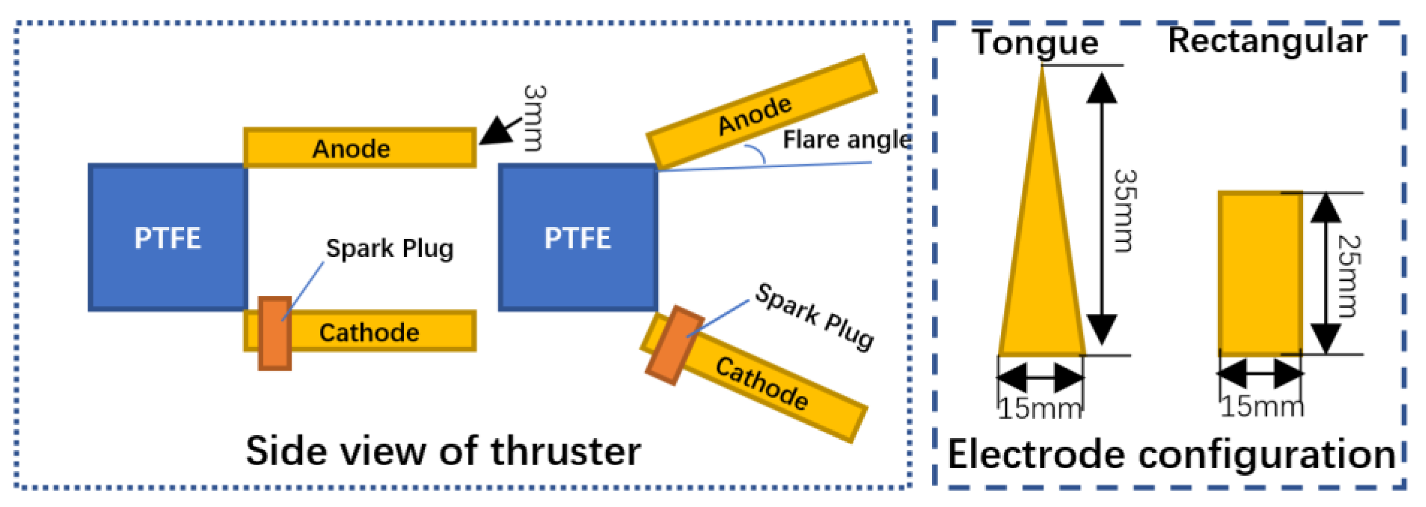
As seen in Figure 2, the thruster electrodes were made of oxygen-free copper shaped similar to rectangles and tongues, respectively. The rectangular electrode was 20 mm long, 15 mm wide, and 3 mm thick.
Increasing the length of the electrode will make more charged particles vanish onto the electrode, reducing the number of charged particles ejected from the thruster to generate effective thrust, thereby reducing the impulse bit of the thruster [11]. Considering that if, with a relatively longer electrode length, the tongue-shaped electrode can still improve the impulse bit of the thruster more effectively than with the rectangular electrode, the benefits of a tongue-shaped electrode configuration for improving thruster performance are even more valid. Thus, the length of the tongue-shaped electrode was 35 mm and its widest width was 15 mm.
The thruster cathode was connected with the external circuit transmission line through a chute, through which the electrode spacing can be adjusted in a range of 0~8 cm. In the experiment, the system performance of the APPT with various electrode designs was examined experimentally under 3 mm and 25 mm electrode spacing, respectively, at varied electrode flare angles (0°, 14°, 26.6°, and 37°), to better compare and analyze the effect of different electrode configurations on the performance of the APPT under the condition of larger and smaller electrode spacing.

2.2. Discharge Parameters Measurement and Estimation Method

As shown in Figure 3, a Tek P5100 high-voltage probe was used to test the APPT’s discharge voltage, and a CWT150 Rogowski coil was used to measure the discharge current. The four-channel Tek DPO4034 oscilloscope, which was powered by a UPS, was used to capture the measured signals.
The measured discharge voltage and current can be used to calculate the energy input into the APPT discharge channel Etr and the efficiency of the system energy translated into discharge energy ηtr, as seen in the following equation:
E t r = 0 V ( t ) i ( t ) d t
η t r = E t r / E 0
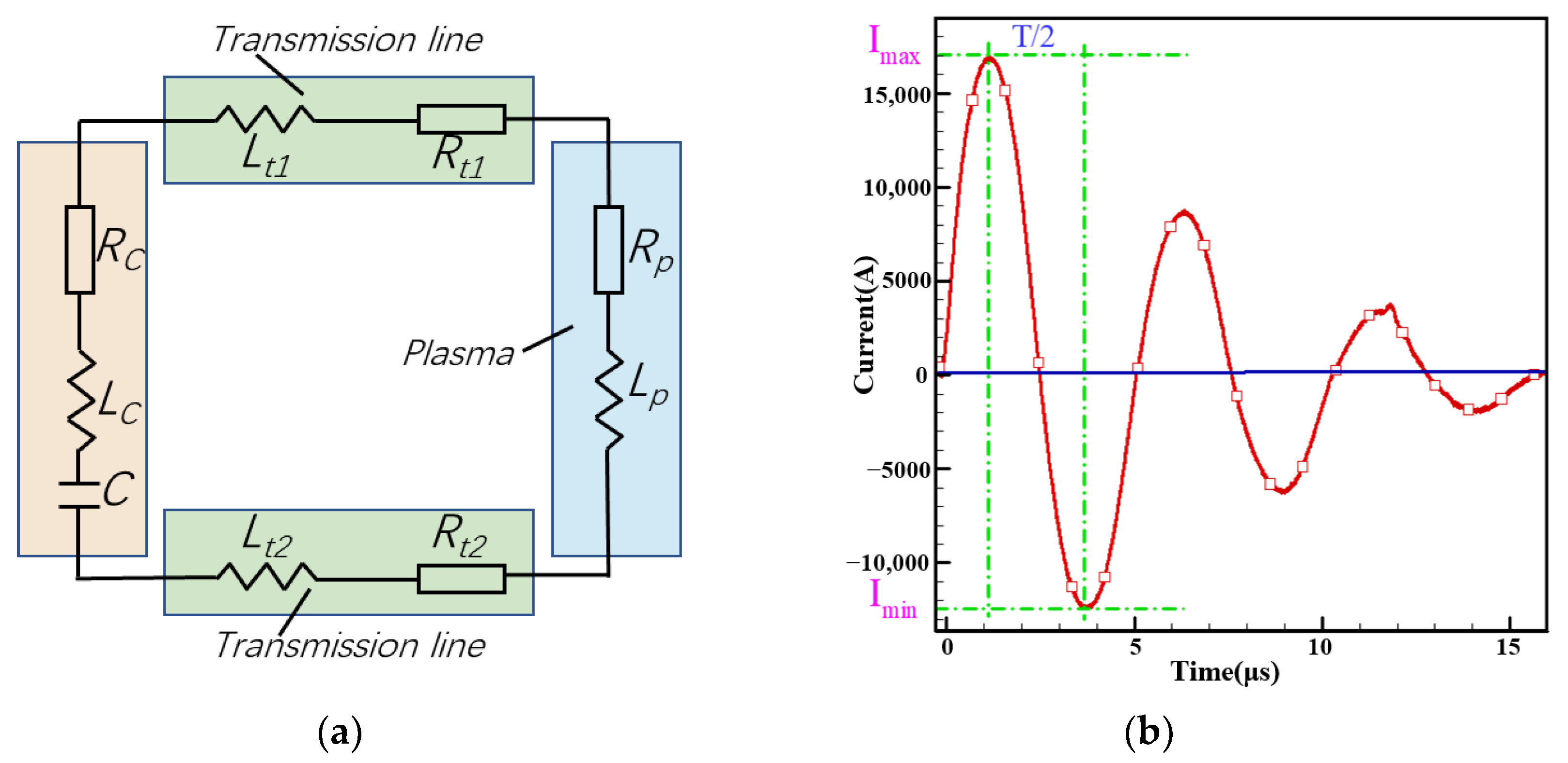
As seen in Figure 4a, the discharge circuit of an APPT can be equivalent to an inductor-capacitor-resistor (LCR) circuit [19,20]. C stands for capacitance and RC and LC for equivalent resistance and inductance of the capacitor, respectively. Rp and Lp stand for plasma resistance and inductance, while Rt1 and Rt2 are the transmission line’s resistance to the electrode. Lt1 and Lt2 are the transmission line’s inductance to the electrode. The external circuit’s inductance and resistance are denoted as Lext and Rext, respectively.
Figure 4b shows the typical discharge current waveform of the APPT. By fitting the waveform, the equivalent resistance Req and inductance Leq of the discharge circuit can be obtained as:
L e q = ( T 2 π ) 2 1 C
R e q = 4 L e q T ln [ | I m a x | | I m i n | ]
and thus:
L e q = L e x t + L p R e q = R e x t + R p
Lext is the sum of LC, Lt1, and Lt2. Rext is the sum of RC, Rt1, and Rt2, and T is the discharge cycle. Imax is the maximum discharge current value and Imin is the minimum discharge current value.
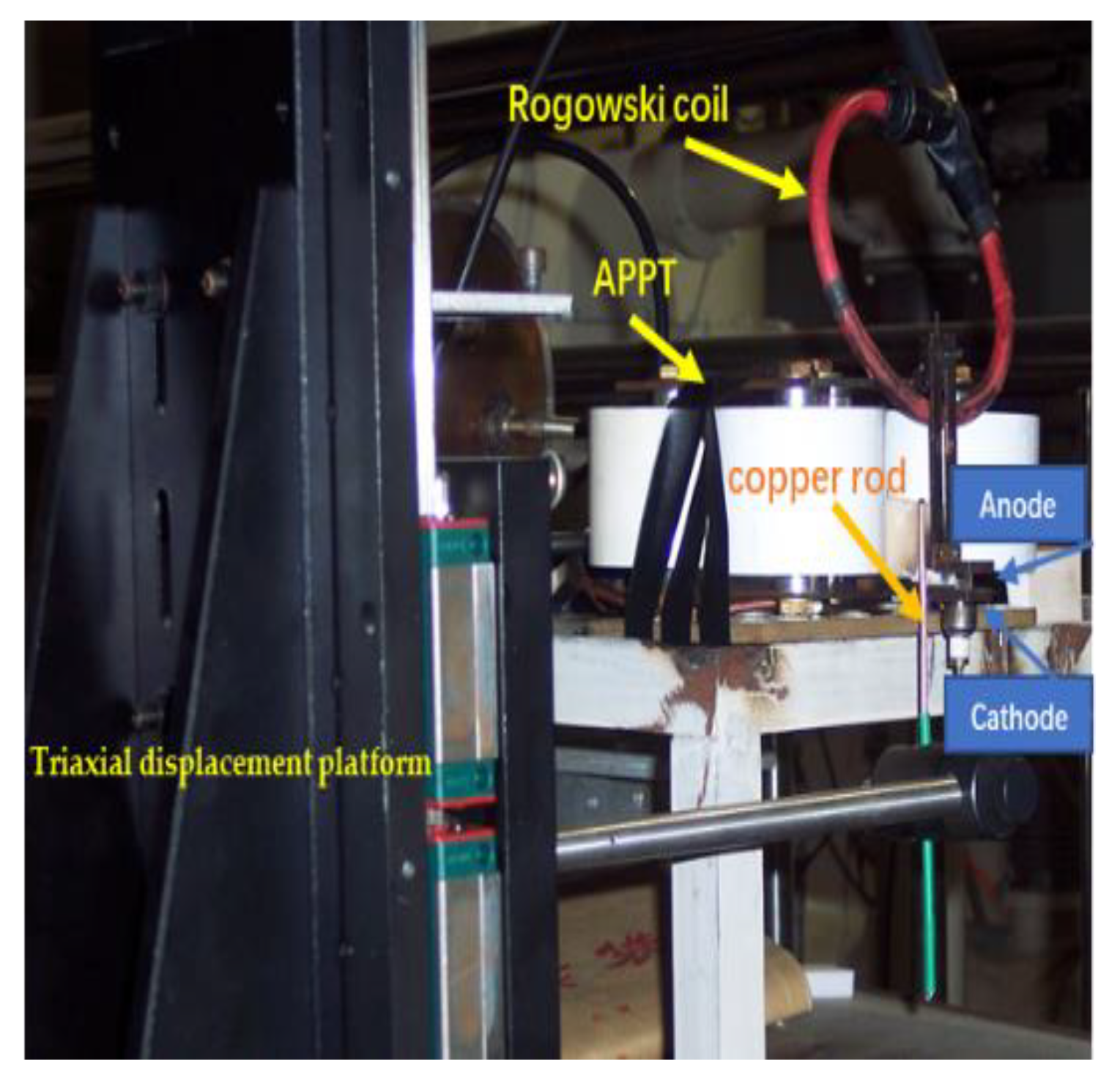
The electrode inductance gradient L′ can be experimentally measured and acquired using the approach, as described in reference [21]. The specific method is as follows: as shown in Figure 5, a copper rod with a diameter of 3 mm and a resistance of 0.45 mΩ is fixed on the triaxial displacement platform, the APPT energy storage capacitor is charged to 1500 V, and the anode and cathode are short-connected by the copper rod at four different positions on the electrode, with an interval of 0.5 mm. According to Equation (3), the average current waveform measured ten times at each position is fitted, and the equivalent inductance Leq of the discharge circuit at this position can be determined. The equivalent inductance of the discharge loop at different locations is fitted using the least squares estimation, and L′ can be determined from the slope of the fitting line.

2.3. APPT Performance Parameters

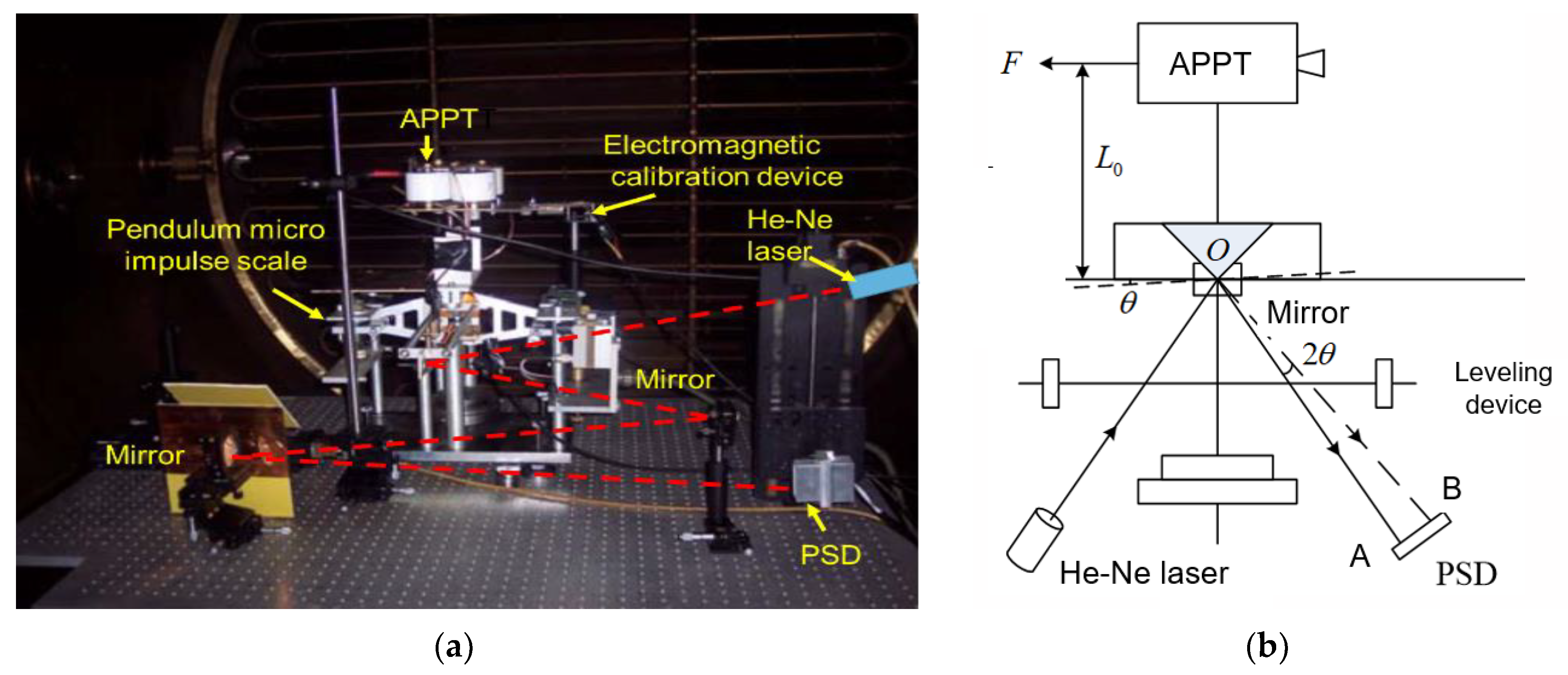
As shown in Figure 6, the impulse bit Ibit was measured using a pendulum micro impulse scale. The laser is reflected by the mirror in the initial state and falls at location A on the position-sensitive detector (PSD). The APPT generates an impulse that causes the pendulum micro impulse scale platform to rotate an angle when it is in operation, shifting the spot position on the PSD from position A to position B. The displacement signal is converted into a voltage signal by the PSD and its signal processing circuit. An electromagnetic calibration device is used to calibrate the pendulum micro impulse scale before measurement. The impulse of the APPT can then be acquired by calibrating the relationship between the impulse and voltage signal. The minimum resolution of the measuring system can reach 0.5 μN-s and the measurement error is 2%, which meets the accuracy requirements of APPT’s impulse bit measurement [22].
The APPT impulse bit is the sum of the impulses generated by the Lorentz force and aerodynamic force [16], as shown below:
I b i t = I E M + I g a s
IEM can be obtained by the Guman estimation formula, as shown below:
I E M = 0 F E M d t 1 2 L 0 I 2 ( t ) d t
Ψ is the time integral value of the square of the current., as shown below:
Ψ = 0 I 2 ( t ) d t
The mass change of the propellant after 5400 times of discharge was weighed using the XS205DU electronic scale, which has a 220 g range and a 0.0001 mg precision. Single-pulse ablation of propellant mass mbit can be determined by averaging. The propellant used was subjected to 5000 discharge ablations in order to form a specific ablation morphology on the surface before being used for relevant experimental measurements. This was performed to reduce the impact of the propellant ablation’s transient effect on the measurement results [23,24].
System-specific impulse Isp, efficiency η, and average velocity of the ablative propellant ve can be obtained using the following formulas:
I s p = I b i t / m b i t g
η = I b i t 2 / 2 m b i t E 0
v e = I b i t / m b i t

3. Results and Discussion

3.1. Effect of Electrode Configuration on Inductance Gradient

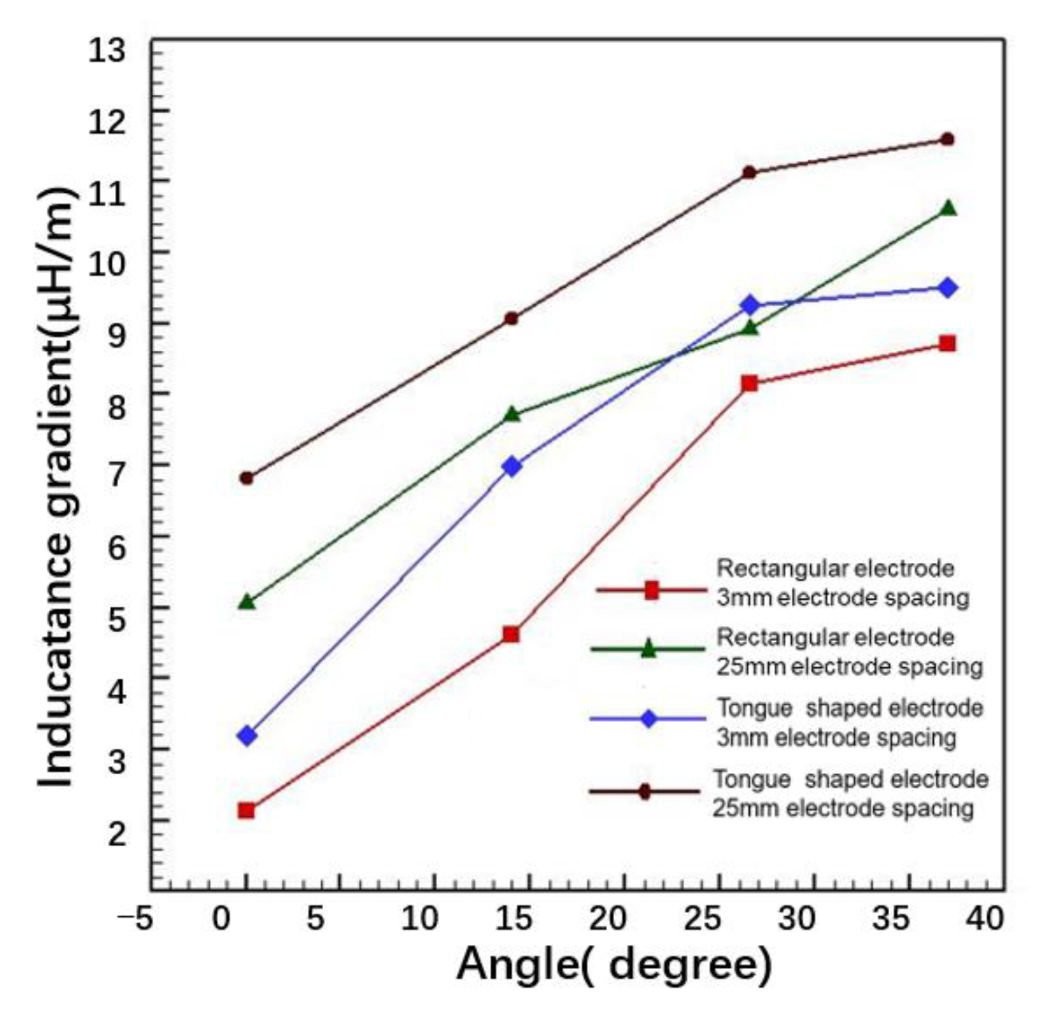
Figure 7 shows that (1) for each configuration electrode with a given electrode spacing, L’ increases as the electrode flare angle increases; (2) for the same electrode spacing and electrode flare angle, the tongue-shaped electrode’s inductance gradient is larger than the rectangular electrode’s; and (3) an electrode of a given configuration has a larger inductance gradient with a larger electrode spacing.

3.2. Effect of the Rectangular Electrode Flare Angle on System Performance

When the electrode spacing is 3 mm and 25 mm, respectively, Figure 8 shows the discharge current waveforms of the rectangular electrode APPT under different electrode flare angles. Discharge circuit parameters that are listed in Table 1 can be obtained using the formulas in Section 2.
When the equivalent inductance and resistance of the discharge circuit increases, as well as when the square integral value of the discharge current gradually reduces, the peak value of the discharge current gradually decreases as the electrode flare angle increases at the same electrode spacing. With a 3 mm electrode spacing, the APPT discharge circuit has a greater integral value of the square of the current than it does with a 25 mm electrode spacing. Additionally, it has a low equivalent inductance and resistance.
According to Table 2, mbit gradually increases under the two electrode spacings as the electrode flare angle increases from 0° to 37°. This is primarily due to the fact that as the flare angle of the electrode increases, the movement of the plasma along the electrode’s expansion direction consumes some of the plasma’s kinetic energy, reducing the plasma jet velocity close to the propellant and lengthening the time the plasma arc interacts with the propellant, resulting in an increase in the ablation quality of the propellant [25].
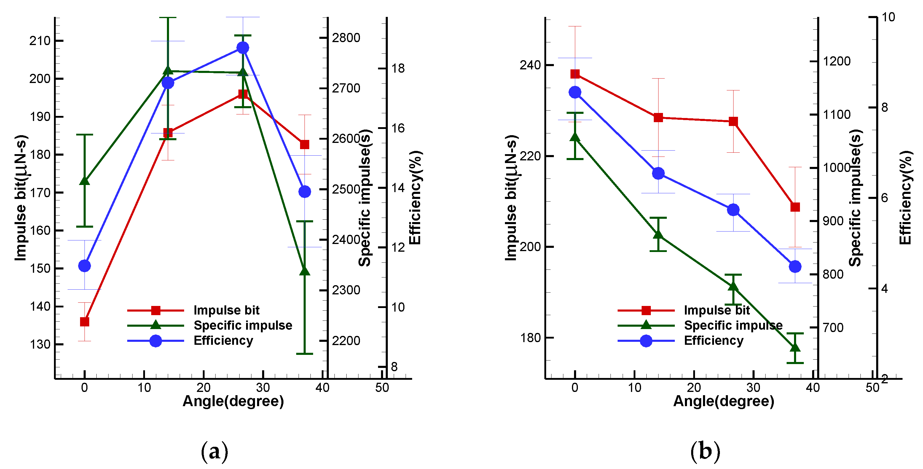
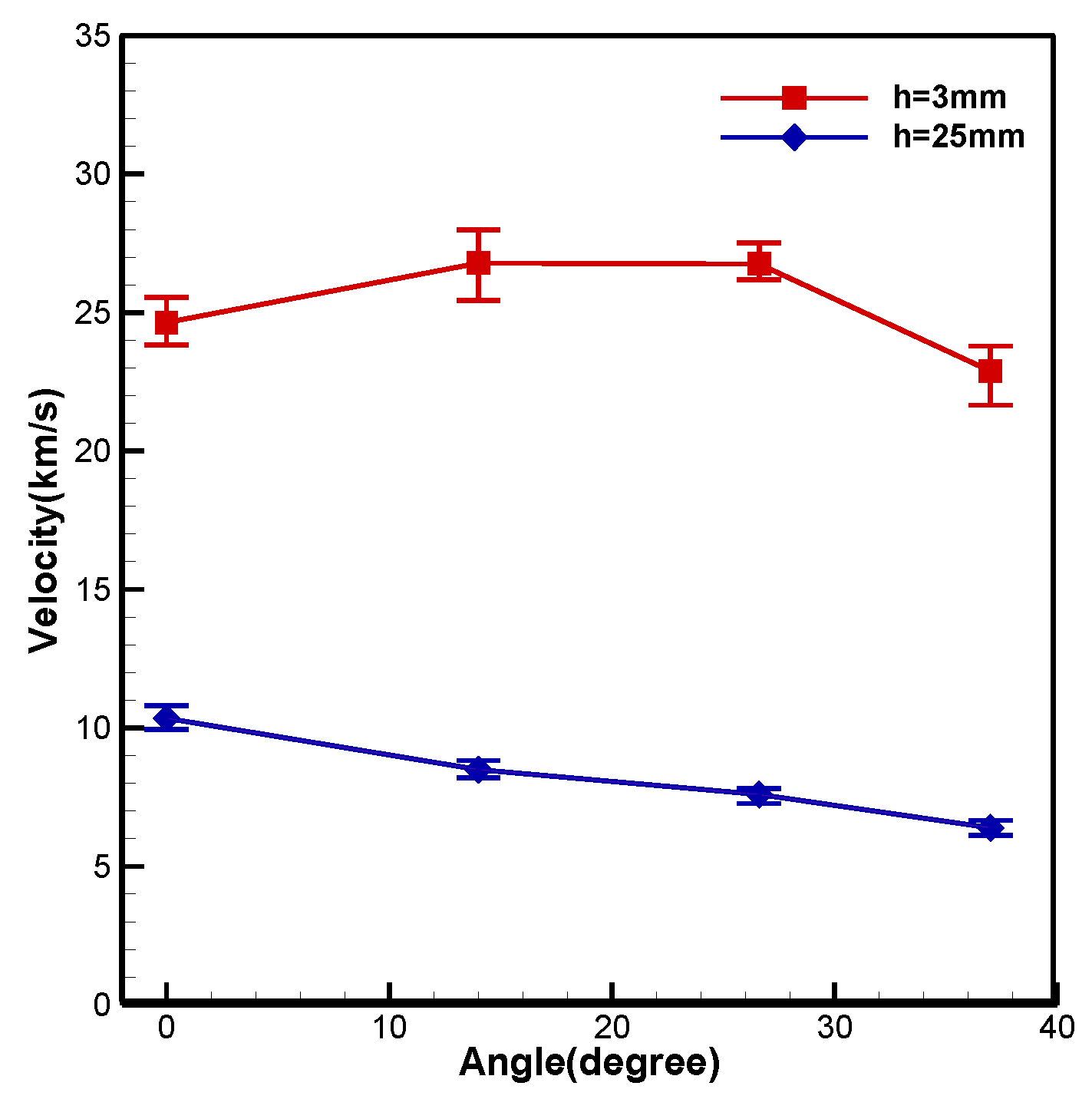
Figure 9 shows the variation trend of the performance of the APPT with the electrode flare angle under the two electrode spacings. At a 3 mm electrode spacing, as the electrode flare angle increases, the electrode inductance gradient gradually increases, and the integral value of the square of the current decreases. According to Equation (7), it can be estimated that the impulse created by the Lorentz force increases with the flare angle, which is a favorable factor for plasma acceleration. Thus, as can be seen in Figure 9a and Figure 10, the thruster impulse bit increases from 135.95 μN-s to 195.96 μN-s, the specific impulse increases from 2514 s to 2731 s, the system efficiency increases from 11.38% to 18.69%, and ve rises from 24.65 km/s to 26.79 km/s as the electrode flare angle increases from 0° to 26.6°.
However, as shown in Table 1 and Table 2, with the increase in the electrode flare angle, the peak value of the discharge current and the integral value of the square of the current decreases significantly, while the ablation quality of the propellant increases.
The high ionization plasma component, which makes the main contribution to the impulse of the thruster, is mainly generated in the first discharge wave peak [26]. The integral value of the square of the current and the Lorentz force on the plasma in the discharge channel are directly correlated. The low discharge current peak is not conducive to the high ionization of the ablative propellant. A drop in the integral value of the square of the discharge current will unavoidably have an impact on the Lorentz force on the plasma.
Additionally, as shown in Table 1, as the electrode flare angle rises, the discharge energy’s transmission efficiency gradually decreases, which means the energy effectively transferred to the discharge channel for plasma acceleration decreases. Meanwhile, more energy is needed to further ionize additional ablated propellant, which is not conducive to a performance improvement of the thruster. Therefore, as the flare angle continues to increase to 37°, the impulse bit, specific impulse, and efficiency of the APPT all decrease.
In contrast to the situation at the 3 mm electrode spacing, as can be seen in Figure 9b, the increase in the electrode flare angle at the 25 mm electrode spacing does not improve thruster performance but instead reduces the APPT impulse bit from 238.01 μN-s to 208.76 μN-s, the specific impulse from 1056 s to 660 s, the efficiency from 8.34% to 4.48%, and the average velocity of the ablative propellant from 10.35 km/s to 6.4 km/s.
According to Table 1 and Table 2, the ablation quality of the propellant is higher at the 25 mm electrode spacing, nearly four times that at the 3 mm electrode spacing. The current peak value is smaller and the integral value of the square of the current is nearly 1/2 of that at the 3 mm electrode spacing. All of these are more unfavorable to the high ionization and acceleration of the ablative propellant, even at the 25 mm electrode spacing, which has a relatively larger electrode inductance gradient. It seemed that the performance of thrusters cannot be improved by increasing the rectangular electrode flare angle at a relatively large 25 mm electrode spacing.

3.3. Effect of the Tongue-Shaped Electrode Flare Angle on System Performance

As shown in Figure 11 and Table 3, when the tongue-shaped electrode is utilized, the equivalent inductance and resistance of the discharge circuit rise with the flare angle, similar to in the APPT with the rectangular electrode. The peak value of the discharge current continuously falls, along with the square integral value of the discharge current. However, compared to the rectangular electrode, the APPT’s peak discharge current, the square integral value of the discharge current, and the energy transfer efficiency are all higher, which is advantageous for improving the thruster’s performance.
As shown in Table 4, mbit increases as the flare angle of the tongue-shaped electrode increases at each electrode spacing. Under the same operating conditions, the tongue-shaped electrode APPT has a higher mass of ablative propellant than the rectangular electrode APPT due to an increase in the integral value of the square of the discharge current.
It can be seen in Figure 12 that, similarly, the impulse bit for the tongue-shaped electrode APPT at the same flare angle is bigger at the 25 mm spacing than at the 3 mm spacing, but the thruster-specific impulse and system efficiency are relatively small. Figure 12a and Figure 13 show that when the electrode spacing is 3 mm, the tongue-shaped electrode APPT’s impulse bit, specific impulse, and system efficiency all increases when the electrode flare angle increases. The average velocity of the ablative propellant also increases accordingly.
According to Figure 7 and Table 1 and Table 3, the tongue electrode has a larger inductance gradient than the rectangular electrode at the same flare angle, and the APPT utilizing the tongue-shaped electrode has a higher integral value of the square of the current. Therefore, the impulse generated by the Lorentz force of the APPT using the tongue-shaped electrode should be considerably larger than that of the APPT employing rectangular electrodes.
However, when the flare angle increases from 0° to 26.6°, the measured impulse bit of the tongue-shaped electrode APPT is smaller than that of the rectangular electrode APPT with the same electrode flare angle. In this angle range, more charged particles vanish onto the electrode due to the increase in the electrode’s length, which is the main reason for the performance degradation of the thruster [15]. However, as the flare angle of the electrode increases to 37°, the constraint of the electrode on charged particles is reduced to a certain extent. At this time, the impulse bit, specific impulse, and efficiency of the APPT with the tongue-shaped electrode are greater than those of the APPT with the rectangular electrode.
According to Figure 12b, when the electrode spacing is 25 mm and the flare angle is 0°, although the tongue-shaped electrode has a larger inductance gradient than the rectangular electrode and the APPT using it has a larger integral value of the square of the current, the tongue-shaped electrode APPT does not perform better than the rectangular electrode APPT for the electrode’s length. However, as the electrode flare angle increases, the constraint of the electrode on charged particles decreases, and other factors such as the electrode’s inductance gradient, the amount of ablative propellant, the impulses produced by the Lorentz force, and the aerodynamic force further increase. We can observe that, when the electrode flare angle is in a range of 14° to 26.6°, despite a minor decrease in impulse with increasing electrode length, it has a higher impulse bit, specific impulse, and system efficiency. The APPT with the tongue-shaped electrode performs noticeably better than the rectangular electrode at the same flare angle.
At a flare angle of 14°, the tongue-shaped electrode APPT thruster’s impulse bit, specific impulse, system efficiency, and average discharge velocity of the propellant are at their highest. As the electrode flare angle rises more, the square integral value of the discharge current falls, which leads to a progressive decline in thruster system performance. When the flare angle is 37°, the performance of the tongue-shaped electrode APPT is only slightly better than that of the rectangular electrode APPT, and its specific impulse value is slightly smaller due to the higher mass of ablative propellant.

4. Conclusions

In the present work, the discharge characteristics, propellant ablation characteristics, and system performance of the APPT with different electrode configurations were investigated experimentally and theoretically under the given initial energy supply mode. Several conclusions were drawn.
(1) The change of electrode configuration will not only change the discharge parameters, but also lead to the change of the equivalent resistance and inductance of the discharge circuit, as well as the change of the discharge characteristics and energy distribution of the system. Under the same electrode configuration, increasing the electrode flare angle can effectively increase the inductance gradient of the electrode, which is a beneficial factor to enhance the Lorentz force on the plasma; however, at the same time, as the electrode flare angle increases, the equivalent inductance and resistance of the discharge circuit increases, and the peak discharge current and the integral value of the square of the current decreases, especially when the electrode flare angle increases to a certain angle. In addition, with the increase in the electrode flare angle, the initial energy transferred to the discharge channel is reduced, and the increase in the electrode flare angle makes the movement of the plasma along the electrode’s expansion direction consumes some of the plasma’s kinetic energy. This increases the action time between the plasma arc and the propellant, resulting in an increase in the ablation quality of the propellant, which requires more energy to further ionize and accelerate additional ablated propellant. It can be concluded that simply increasing the electrode flare angle has certain limitations in optimizing thruster performance.
(2) In addition to having a higher inductance gradient degree than rectangular electrodes, tongue-shaped electrodes can more effectively reduce the equivalent inductance and resistance of the discharge circuit. This allows the APPT to obtain a higher peak discharge current and squared integral value of the discharge current, increasing the discharge energy transferred into the discharge channel from the initial energy, which are effective factors that can enhance the performance of the thruster. However, due to an increase in the square integral value of the discharge current, the tongue-shaped electrode APPT has a greater mass of ablative propellant than the rectangular electrode APPT, which is not favorable for system-specific impulse and efficiency.
(3) In order to minimize the impact on the thrust output of the thruster caused by the increase in charged particles that die on the electrodes, the length of the electrodes and the space between the positive and negative electrodes must also be carefully chosen. The APPT current square integral value is larger when the electrode spacing is small, but the electrode inductance gradient is smaller and the electrode’s constraint on charged particles is relatively strong, so the APPT impulse bit is also small. The ablation mass of the propellant is small, so the APPT has a relatively large specific impulse at a small electrode spacing, and the increase in the electrode flare angle also improves the thruster performance more obviously at a small electrode spacing.

Author Contributions

Methodology, R.Z. and W.X.; validation, Z.T., W.X. and D.H.; investigation, R.Z. and Z.T.; writing—original draft, R.Z.; supervision, Z.T.; funding acquisition, R.Z. All authors have read and agreed to the published version of the manuscript.

Funding

This research was funded by the Natural Science Foundation of Hunan Province, China (Grant No. 2020JJ7080).

Data Availability Statement

The data presented in this study are included within the article.

Conflicts of Interest

The authors declare no conflict of interest.

References

  1. Ou, Y.; Wu, J.J.; Zhang, Y.; Li, J.; Tan, S. Theoretical Modeling and Parameter Analysis of Micro-Pulsed Plasma Thruster. Energies 2018, 11, 1146. [Google Scholar] [CrossRef] [Green Version]
  2. Zhao, Y.Z.; Zhang, Y.; Wu, J.J.; Ou, Y.; Zheng, P. Characteristics of plasma in a novel laser-assisted pulsed plasma thruster. Rev. Mod. Phys. 2019, 3, 3–5. [Google Scholar] [CrossRef]
  3. Wu, Z.W.; Huang, T.K.; Liu, X.Y.; Ling, W.Y.L.; Wang, N.F.; Ji, L.C. Application and development of the pulsed plasma thruster. Plasma. Sci. Technol. 2020, 22, 131–144. [Google Scholar] [CrossRef]
  4. Lev, D.; Myers, R.M.; Lemmer, K.M.; Kolbeck, J.; Koizumi, H.; Polzin, K. The technological and commercial expansion of electric propulsion. Acta Astronaut. 2019, 159, 213–227. [Google Scholar] [CrossRef]
  5. Zhang, R.; Xi, W.X.; Huang, Q. Influence of Different Energy Supply Methods on Performance of Ablative Pulsed Plasma Thrusters. Front. Energy Res. 2021, 9, 752017. [Google Scholar] [CrossRef]
  6. Wu, Z.; Sun, G.; Huang, T.; Liu, X.; Xie, K.; Wang, N. Optimization of the energy distribution in ablative pulsed plasma thrusters. AIAA J. 2018, 56, 3024–3034. [Google Scholar] [CrossRef]
  7. Zhang, Z.; Ling, W.Y.L.; Tang, H.b.; Cao, J.B.; Liu, X.Y.; Wang, N.F. A review o Energy Operationf the characterization and optimization of ablative pulsed plasma thrusters. Rev. Mod. Plasma Phys. 2019, 3, 3–5. [Google Scholar] [CrossRef]
  8. Guman, W.J.; Peko, P.E. Solid Propellant Pulsed Plasma Micro-thruster Studies. In Proceedings of the AIAA the 6th Aerospace Sciences Meeting, New York, NY, USA, 22–24 January 1968. [Google Scholar]
  9. Ling, Y.L.; Zhang, S.; Liu, X.Y.; Zhang, Z.; Tang, H.B. Spectroscopic plasma emission from a pulsed plasma thruster with asymmetric electrodes. In Proceedings of the AIAA Propulsion and Energy 2019 Forum, Indianapolis, IN, USA, 19–22 August 2019. [Google Scholar]
  10. Ling, Y.L.; Zhang, S.; Liu, X.Y.; Wang, N.F.; Zhang, Z.; Tang, H.B. A study on asymmetric electrodes for pulsed plasma thrusters. In Proceedings of the 2018 Joint Propulsion Conference, Cincinnati, OH, USA, 9–11 July 2018. [Google Scholar]
  11. Zhang, Z.; Ren, J.X.; Tang, H.B.; Xu, S.T.; Ling, Y.L.; Cao, J.B. Inter-electrode discharge of an ablative pulsed plasma thruster with asymmetric electrodes. Plasma Sci. Technol. 2018, 27, 124003. [Google Scholar] [CrossRef]
  12. Zhang, Z.; Ren, J.X.; Tang, H.B.; Ling, Y.L.; Thomas, M.Y. An ablative pulsed plasma thruster with a segmented anode. Plasma Sci. Technol. 2017, 27, 015004. [Google Scholar] [CrossRef]
  13. Arrington, L.A.; Haag, T.W.; Pencil, E.J.; Meckel, N.J. A Performance Comparison of Pulsed Plasma Thruster Electrode Configurations. In Proceedings of the 25th International Electric Propulsion Conference, Cleveland, OH, USA, 24–28 August 1997. [Google Scholar]
  14. Pottinger, S.J.; Scharlemann, C.A. Micro Pulsed Plasma Thruster Development. In Proceedings of the 30th International Electric Propulsion Conference, Florence, Italy, 17–20 September 2007. [Google Scholar]
  15. Palumbo, D.J.; Guman, W.J. Effects of propellant and electrode geometry on pulsed ablative plasma thruster performance. J. Spacecr. Rock. 1976, 13, 163–167. [Google Scholar] [CrossRef]
  16. Pottinger, S.J.; Krejci, D.; Acharlemann, C.A. Pulsed plasma thruster performance for miniaturized electrode configurations and low energy operation. Acta Astronaut. 2011, 68, 1996–2004. [Google Scholar] [CrossRef]
  17. Schönherr, T.; Nawaz, A.; Herdrich, G.; Röser, H.P. Influence of the electrode shape on the performance of the pulsed MPD thruster SIMP-LEX. J. Propul. Power 2009, 25, 380–386. [Google Scholar] [CrossRef]
  18. Nawaz, A.; Albertoni, R.; Auweter-Kurtz, M. Thrust Efficiency Optimization of The Pulsed Plasma Thruster SIMP-LEX. Acta Astronaut. 2010, 67, 440–448. [Google Scholar] [CrossRef]
  19. Wu, J.J.; Zhang, Y.; Ou, Y. Experimental investigation on the plasma morphology of ablative pulsed plasma thruster with tongue-shaped and flared electrodes. Plasma Sci. Technol. 2020, 22, 094007. [Google Scholar] [CrossRef]
  20. Ling, W.Y.L.; Schönherr, T.; Koizumi, H. Discharge characteristics of an ablative pulsed plasma thruster with non-volatile liquid propellant. Appl. Phys. Lett. 2017, 111, 1452–1461. [Google Scholar] [CrossRef]
  21. Koizumi, H.; Furuta, Y.; Komurasaki, K. A Pulsed Plasma Thruster Using Water as the Propellant. In Proceedings of the 40th AIAA/ASME/SAE/ASEE Joint Propulsion Conference, Fort Lauderdale, FL, USA, 11–14 July 2004. [Google Scholar]
  22. Zhang, Y.; Zhang, D.X.; Wu, J.J.; He, Z.; Zhang, H. A novel laser ablation plasma thruster with electromagnetic acceleration. Acta Astronaut. 2016, 127, 438–447. [Google Scholar] [CrossRef]
  23. Spanjers, G.G.; Malak, J.B.; Leiweke, R.J.; Spores, R.A. Effect of Propellant Temperature on Efficiency in the Pulsed Plasma Thruster. J. Propul. Power 1998, 14, 545–553. [Google Scholar] [CrossRef] [Green Version]
  24. Keidar, M.; Boyd, I.D. Antonsen, E.L. Optimization issues for a micropulsed plasma thruster. J. Propul. Power 2006, 22, 48–55. [Google Scholar] [CrossRef]
  25. Ying, L.; Zhou, J.; Miao, W.B.; Sun, M.B.; Yang, L.; Wu, J.J. Simulation Study for design of pulsed plasma thruster. J. Solid Rocket. Technol. 2010, 33, 419–424. [Google Scholar]
  26. Markusic, T.E.; Spores, R.A. Spectroscopic emission measurements of a pulsed plasma thruster plume. In Proceedings of the 33rd Joint Propulsion Conference and Exhibit, Seattle, WA, USA, 6–9 July 1997. [Google Scholar]
Figure 1. (a) Vacuum chamber and (b) the APPT used in the experiment.
Energies 15 09389 g001
Figure 2. Schematic diagram of the electrode configuration.
Energies 15 09389 g002
Figure 3. Schematic of the APPT electrical circuit and instrumentation system.
Energies 15 09389 g003
Figure 4. (a) Equivalent circuit diagram and (b) typical discharge current waveform of the APPT.
Energies 15 09389 g004
Figure 5. Inductance gradient measuring device diagram.
Energies 15 09389 g005
Figure 6. (a) Pendulum micro impulse scale and (b) a schematic diagram of working principle.
Energies 15 09389 g006
Figure 7. The variation of the inductance gradient with the flare angle of different electrode configurations.
Energies 15 09389 g007
Figure 8. The rectangular electrode APPT discharges current waveforms at various flare angles: (a) the electrode spacing is 3 mm and (b) the electrode spacing is 25 mm.
Energies 15 09389 g008
Figure 9. The APPT performance of rectangular electrodes with variable flare angles: (a) the electrode spacing is 3 mm and (b) the electrode spacing is 25 mm.
Energies 15 09389 g009
Figure 10. The variation of the average velocity of the ablative propellant with the flare angle of the rectangular electrode.
Energies 15 09389 g010
Figure 11. The tongue-shaped electrode APPT discharges current waveforms at various electrode flare angles: (a) the electrode spacing is 3 mm and (b) the electrode spacing is 25 mm.
Energies 15 09389 g011
Figure 12. The APPT performance of tongue-shaped electrodes with variable flare angles: (a) the electrode spacing is 3 mm and (b) the electrode spacing is 25 mm.
Energies 15 09389 g012
Figure 13. The variation of the average velocity of the ablative propellant with the flare angle of the tongue-shaped electrode.
Energies 15 09389 g013
Table 1. The APPT discharge circuit parameters with the rectangular electrode with different flare angles.
Electrode
Spacing
Flare AngleImax [KA]Leq [nH]Req [mΩ]Ψ [A2·s]ηtr [%]
3 mm17.0656.928.61884.1768.73
14°15.8361.7915.55509.2968.71
26.6°14.3564.6315.79487.0260.86
37°13.1864.5816.12456.1257.65
25 mm15.2364.5220.03446.1579.71
14°14.9664.7621.52358.0979.24
26.6°14.4364.9324.48319.5478.97
37°13.1164.8626.25274.7972.81
Table 2. The rectangular electrode APPT ablation characteristics of the propellant at various electrode flare angles, the unit of mbit is microgram.
Electrode Spacing14°26.6°37°
3 mm 5.52 ± 0.426.94 ± 0.347.32 ± 0.377.98 ± 0.28
25 mm 22.99 ± 0.3326.69 ± 0.2429.93 ± 0.4232.23 ± 0.25
Table 3. The tongue-shaped electrode APPT discharge circuit parameters at various electrode flare angles.
Electrode
Spacing
Flare
Angle
Imax [KA]Leq [nH]Req [mΩ]Ψ [A2·s]ηtr [%]
3 mm21.0651.8912.26968.7680.23
14°19.0553.1212.41870.2483.65
26.6°17.5354.0712.98789.980.81
37°17.2656.6514.69649.183.47
25 mm20.155.4119.70855.0188.59
14°18.3558.2319.92712.5790.04
26.6°16.160.6821.27551.9886.78
37°16.266.8422.91499.5480.48
Table 4. The tongue-shaped electrode APPT ablation characteristics of propellant at various electrode flare angles, the unit of mbit is microgram.
Electrode Spacing14°26.6°37°
3 mm 6.45 ± 0.368.71 ± 0.249.022 ± 0.238.17 ± 0.44
25 mm 27.23 ± 0.2830.94 ± 0.1434.67 ± 0.3241.25 ± 0.22
Publisher’s Note: MDPI stays neutral with regard to jurisdictional claims in published maps and institutional affiliations.