Review

Review of Current State-of-the-Art Research on Photovoltaic Soiling, Anti-Reflective Coating, and Solar Roads Deployment Supported by a Pilot Experiment on a PV Road

Photovoltaics Laboratory, School of Physics, Engineering and Technology, University of York, York YO10 5DD, UK
*
Author to whom correspondence should be addressed.
Energies 2022, 15(24), 9620; https://doi.org/10.3390/en15249620
Submission received: 22 November 2022 / Revised: 13 December 2022 / Accepted: 14 December 2022 / Published: 19 December 2022

Abstract

:
The objective of this review paper is to provide an overview of the current state-of-the-art in solar road deployment, including the availability of anti-reflection and anti-soiling coating materials for photovoltaic (PV) technology. Solar roads are built using embedded PV panels that convert sunlight into electricity, which can be stored for later use. Prototypes of solar roads have been tested on various continents, but the lack of suitable PV materials has limited their effectiveness compared to conventional PV systems. By analyzing the existing literature on solar roads and PV materials, including anti-reflection and anti-soiling coatings, we aim to identify gaps in knowledge and propose an action plan to improve the resiliency, durability, and reliability of PV panels in solar road applications. This will enable the deployment of solar roads as a clean, renewable energy source.

1. Introduction

Developing renewable energy sources is one of the most pressing concerns in a world where environmental challenges are recurring, and fossil fuel supplies are dwindling. As a renewable energy source, photovoltaic (PV) technologies are superior because they are energy efficient, reliable, and environmentally friendly [1]. However, currently, all technological efforts are not solely directed towards improving PV performance and solar cells but also toward mitigating external factors that can adversely affect the conversion efficiency of solar panels. The soiling of the PV modules is one of these factors. The dust accumulation on the modules gradually diminishes the PV cover glass’ transparency over time, eventually reducing the amount of energy produced by the PV modules [2]. An excellent demonstration of soiled PV modules compared to a clean one can be seen in Figure 1. According to the findings of a global techno-economic study, global power losses due to soiling are projected to reach 4 to 7% by 2023 due to excessive PV deployment in polluted regions [3].
As opposed to other types of power degradation, a reduction in power loss caused by soiling can be accomplished by cleaning the PV modules, and the degradation resulting from soiling can be completely restored. However, repetitive cleaning will increase the cost of operating and maintaining the PV modules, particularly in areas with limited access to water and labor [5]. For this reason, a lot of effort is being put into optimizing the cleaning strategies in a variety of approaches such as dry or wet, manual, or automated, as well as the type of cleaning material used to clean. In addition, there are other mitigation strategies for reducing dust deposition using natural mechanics such as wind and rain, as well as developing anti-soiling coatings to maximize the effectiveness of the cleaning process.
Solar PV panels are commonly made from crystalline silicon solar cells, which are the most widely used type of PV module. CIGS (copper indium gallium selenide) and GdTe (gadolinium telluride) solar cells are also used in PV modules. GaAs (gallium arsenide) solar cells are another type of PV module, but they are not as commonly used as the others because they are more expensive to produce [6,7]. Crystalline silicon solar cells are used in a wide range of applications, from small portable devices to large-scale solar power plants. CIGS and GdTe solar cells are typically used in smaller applications, such as portable solar chargers and building-integrated PV systems. GaAs solar cells are used primarily in specialized applications, such as satellite power systems and high-efficiency PV systems [8]. The CIGS solar panels have several advantages over other types of solar panels. For example, they are generally more efficient at converting sunlight into electricity than other types of solar panels, including crystalline silicon solar panels. They are also thin and lightweight, which makes them easier to install and integrate into buildings. Additionally, CIGS solar panels are flexible, which allows them to be used in a wider range of applications than other types of solar panels. Finally, CIGS solar panels are made from a combination of relatively abundant and inexpensive materials, which makes them less expensive to produce [9].
When a solar cell is exposed to sunlight, it absorbs the energy from the light and converts it into electricity. However, some of the absorbed energy is lost as heat, which can increase the temperature of the solar cell and reduce its efficiency. This is known as the “heat effect” on solar cells [10]. There are several ways to mitigate the heat effect on solar cells. One common approach is to use cooling systems, such as fans or water cooling, to remove the heat from the solar cells. This can help to keep the temperature of the solar cells within a reasonable range and maintain their efficiency. Another approach is to use materials with high thermal conductivity in the construction of the solar cells [11]. This can help to dissipate the heat more effectively and reduce the temperature of the solar cells. Overall, it is important to consider the heat effect on solar cells and take steps to mitigate it to maximize their efficiency and lifespan. This can be done using cooling systems and high-conductivity materials, as well as other strategies such as optimizing the design of the solar cell and selecting appropriate operating conditions.
Perovskite solar cells are a new generation of thin film solar cells that have attracted significant attention in recent years due to their potential to offer high efficiency and low cost [12,13]. Perovskite is a type of crystal structure that has unique optical and electrical properties, making it well-suited for use in solar cells. Perovskite solar cells are made by depositing a layer of perovskite material on a substrate, such as glass or plastic, and then exposing it to light. The perovskite layer absorbs the energy from the light and generates electricity, much like other types of solar cells. Perovskite solar cells have several advantages over other types of solar cells. For example, they can be made using solution-based processing techniques, which are relatively simple and inexpensive. This makes it possible to produce perovskite solar cells on a large scale at low cost. Perovskite solar cells are also flexible and lightweight, which makes them well-suited for use in a variety of applications. Additionally, perovskite solar cells have demonstrated high efficiency in laboratory tests, with some achieving efficiency levels above 20% [14]. Despite these advantages, perovskite solar cells are not yet widely used in commercial applications. This is because they are still in the early stages of development, and there are several challenges that need to be overcome before they can be widely adopted. For example, the stability of perovskite solar cells is a major concern, as they can degrade quickly when exposed to light and heat. Additionally, there are concerns about the safety and environmental impact of the materials used in perovskite solar cells [15]. Overall, perovskite solar cells are a promising new technology with the potential to offer high efficiency and low cost. However, more research and development are needed before they can be widely used in commercial applications.

2. Aim and Organization of this Paper

The purpose of this review is to present an analysis and summary of recent published work on two key areas of photovoltaic (PV) applications: PV soiling and PV solar roads. This includes a description of recent developments in mitigation, diagnostics, and materials selection for anti-reflecting and anti-soiling coatings for solar cells. The paper also aims to summarize the current gaps in knowledge and outline exciting challenges in these areas of research, including the deployment of solar roads. In addition, the review discusses existing techniques for inspecting PV solar panels, such as electroluminescence (EL), photoluminescence (PL), and thermal imaging.
In this paper, we present our findings in the following manner. In Section 3 and Section 4, factors affecting PV soiling as well as state-of-the-art PV soiling mitigation and clearing techniques are presented. Section 5 discusses the solar road deployment concept. Additionally, Section 6 summarizes all the concepts and ideas discussed in this paper. Finally, Section 7 draws the main conclusions of this paper and outline future potential work.

3. Factors Affecting PV Soiling

As a phenomenon, soiling depends on various factors, including location, metrological, technological, and climate conditions. Since dust deposits on the cover of the PV cells, soiling can partially shade the cells, resulting in a substantial loss of power [16]. Several factors have a significant impact on the soiling process, including:
(1)
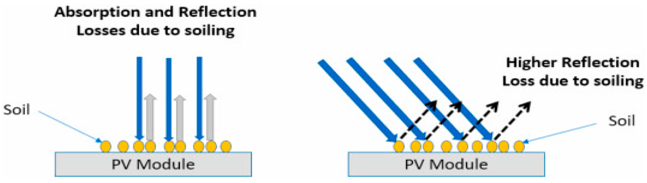
Tilt Angle: because dust particles tend to accumulate more on the horizontal surface than the tilted angles, the effect of gravity will increase with the increasing tilt angle [16]. In Figure 2, a contaminated PV module will suffer either reflections or absorption losses, however, when there is a greater angle of incidence than 0°, there will be a greater amount of reflection loss [17].
(2)
Orientation: PV modules exposed to the wind will accumulate dust at a higher rate than when they are facing the opposite direction with the wind blowing straight down on them [18].
(3)
Ambient Temperature: a recent study has found that temperature affects the viscosity of the air, which affects the concentration of airborne particles. Therefore, when the temperature decreases, the viscosity of the air will increase. This, in turn, will lead to an increase in the concentration of aerosols in the atmosphere, resulting in a higher soiling rate [19].
(4)
Relative Humidity: an increasing body of evidence indicates that particles adhere more easily to surfaces at high relative humidity [20]. An experiment that was carried out in Saudi Arabia in 2014 measured the adhesion strength between two different flat silica and 48 μm silica beads in different humidity levels. It was found that when the humidity increases by at least 20% RH, it can reduce the PV module’s output power by 8% [21].
(5)
Characteristics of the site: Land features are considered by many to be a contributing factor to increasing aerosol levels, which in turn increase soiling rates in that area [16]. As human activity occurs throughout an urban area, the density of particles that form the soil is influenced by the amount of human activity involved [22]. Additionally, forests influence pollination processes through the pollen and dried leaves they produce [23].
(6)
Wind Velocity: In terms of the wind’s impact, there are two main aspects to consider. One is that as the wind speed increases, it will cause the accumulation of dust to increase [24]. In some papers, however, there has been an argument that with the increase in wind speed, the panels will be cleaned against dust deposition if they are originally oriented towards the wind movement [25].
(7)
PV Technology: PV module degradation caused by soiling is mainly determined by the type of PV technology. A study found that monocrystalline PV modules degraded by 20%, while polycrystalline PV modules degraded by 16% with a dust accumulation rate of 0.98 gm/cm2 [26].
(8)
Dust Properties: Depending on their chemical, biological and physical properties, dust particles can display various characteristics. Due to this, the amount of dust that will accumulate will differ depending on the properties of the surface. For example, on a PV surface, small particles of dust can settle more readily than large particles [27].
(9)
Aerosols, fungi, and other contaminants: As a result of the absorption and scattering of sunlight in specific wavelength ranges by atmospheric aerosols, solar energy applications experience significant spectral shifts [28,29]. In several studies, fungal growth on solar panels and glass coupons aged at least 6 months has been shown to contribute to soiling through biological growth, particularly fungal growth on the surfaces of the panels [30,31] Furthermore, pollen behaves as a seasonal, local-scale soiling agent. Pollen can build up on PV modules, especially near the lower edge of the modules, reducing energy conversion [32].

4. PV Soiling Mitigation and Cleaning Techniques

A wide range of research is being conducted in soiling mitigation to develop methods and techniques for reducing dust particles on the surface of PV modules. It is imperative to perform periodic cleaning to recover the energy lost by dust. Despite this, environmental factors also play an influential role in dictating the frequency at which cleaning should be performed [33]. As a result, many different techniques exist to remove dust from a surface, including manual cleaning with water and labor or using robots, vibrating or electrostatic machines, and so on [34].
Cleaning using manpower is a traditional approach to removing dust from the PV surface, and if it is organized in a systematic way, it can be an efficient method since it can be used to remove cemented dust to a great extent. As with any technique, there are some drawbacks associated with it. The first is that the method requires a lot of water that can be difficult to obtain, especially in places with scarcity of water. The second is that the method requires a lot of labor which increases maintenance costs of the system [35].
Furthermore, among several passive cleaning techniques, robots are one of the techniques that require a great deal of energy to operate. There are both contact and contactless devices, which are static non-pressurized systems requiring considerable water to run [5]. Figure 3 shows different robots used to clean the PV surface of solar panels. In Figure 3a the robot is Gekko, which was manufactured by Serbot, located in Switzerland, and used a combination of brush and deionized water to clean the PV surface. Figure 3b is the Oasis robot from the SunPower company in America which works on the same principle as the Gekko robot. Figure 3c is Hector from the Sener company in Spain which requires a truck to assemble. Figure 3d is the Paris robot, which is also from the Sener company. There is a growing market for this type of technology, and it is expected that new modules with more autonomy and less need for manual intervention will appear on the market in the near future.
There are several cost-effective cleaning approaches for solar PV panels. One approach is to use mechanical cleaning methods, such as brushing or wiping the panels with a soft cloth or brush. This can be done manually, using a ladder and other tools, or with the help of specialized cleaning robots that can climb onto the roof and clean the panels automatically. Mechanical cleaning methods are relatively inexpensive and can be effective at removing light dust and debris from the panels. Another cost-effective cleaning approach is to use water to wash the panels. This can be done by spraying the panels with water from a hose or pressure washer, or by using a water-fed pole system that uses purified water to clean the panels. Water washing is more effective at removing stubborn dirt and grime from the panels, but it can also be more expensive and time-consuming than mechanical cleaning methods.
Overall, the most cost-effective cleaning approach for solar PV panels will depend on the specific conditions and requirements of each installation. In general, a combination of mechanical cleaning and water washing can provide the best balance of effectiveness and cost-efficiency. It is also important to regularly inspect and maintain the panels to ensure that they are functioning at their maximum efficiency.
An electrostatic concept has been developed utilized by an electrodynamic screen (EDS) that is based on the particles moving because of the electrostatic reactions between the dust particles, which can either be positively or negatively charged. Essentially, electrodynamics is a set of parallel electrodes engraved on the PV material’s surface in a parallel pattern [36]. During the energization process of the electrodynamic screen, the electrodes are energized by the current, which in turn will cause the electrode waves to transport all the charged particles through the electrodes, as shown in Figure 4. Despite this, it has been reported that this method can result in another form of fault in the PV modules, known as potential induced degradation (PID). The PID occurs due to the leakage of the current from the PV module to the surface because of applying the EDS technique. It is worth noting that PID can also result due to failure in the PV inverter and grounding issues in the PV assets [37].
As a self-cleaning technique, anti-soiling coating (ASC) is one that does not require an excessive amount of energy for its performance. Ultimately, the ASC surface is made as a transparent surface that has been developed based on hydrophobic and hydrophilic characteristics as well as photocatalytic properties. As a result of the photocatalytic action of the coating and its hydrophobic properties, the dust will be broken down by the effect of ultraviolet radiation, and the dust will then be displaced by the spherical drops formed by the coatings as they slide down the surface and displace the dust as shown in Figure 5 [38]. As an alternative, hydrophilic properties will cause water to spread over the surface and sweep any dust with it [39]. As a result of the study, it was found that the soiling rate decreased with coated surfaces when compared to uncoated surfaces by 0.53% and 0.59%, respectively [40].
Among the ASC techniques, sol-gel-based is the most popular and easiest to implement. Additionally, a key aspect of the adaptability of the sol-gel method is its ability to integrate easily with other forms of fabrication, such as laser engraving and plasma technology [41]. A schematic that shows a complete overview of the process of making sol-gel for the development of ASC can be seen in Figure 6. Different methods are available to test the performance and durability of coatings such as determining the performance transmittance, the contact angle between the coating and the water, reflections, and so on. Several methods can be used for testing durability of coatings, which include thermal cycling, dump heat, ultraviolet exposure, abrasion test and so on, which are all based on the standards of the International Electrotechnical Commission (IEC) [42].
Different approaches have been used to certify different ASCs for efforts involving laboratory studies or outdoor studies which have lasted for days, weeks or even years in order to evaluate the ASC’s performance with respect to its capabilities [43]. Yet, most of those studies focus on a single ASC or have limited location tests since each ASC performs differently in different locations.
Several tests have been conducted to determine whether different ASCs degrade appropriately as they age, and one of those tests was conducted in Denmark using two different ASCs: one per fluorinated silane layer, and the other hexamethyldisilane and functionalized silica nanoparticles that were exposed outside for 24 weeks [44]. Analyzing the ASC using SEM before exposing the silane layer ASC outside revealed defects, as shown in Figure 7, which may cause premature failure and compromise its durability. Also, it demonstrated a reduction in water contact angles (WCA) for the silane layer (2%) and silica nanoparticles (5.2%), which had an impact on hydrophobicity [44].
In addition, ASC development is a major concern for all the world right now, but there are three things that should be taken into consideration when developing different ASCs:
  • It is expected that the ASC will have exceptional dust repellency.
  • ASC optical transmittance should be equal to or greater than solar cover glass.
  • The durability of an ASC should be similar to that of a solar PV panel (25 years).
As a result of the complexity of the factors that affect soiling, it makes comprehending them more challenging because some of these factors have a double effect, both positive and negative. In addition, due to the fact that the effects are linked to one another, it is challenging to consider each one separately. There have been many different cleaning techniques developed over the last few decades. Still, it is hard to pin down the actual performance of each method because the PV panels’ efficiency majorly depends on the site’s conditions and environmental factors.
There is a growing amount of research taking place on new cleaning mechanisms, as a result of which, there exists an underlying problem with using a cleanser, usually water, to clean. Due to their anti-static properties and potential photocatalytic capability, ASCs are often capable of extending the time between cleaning, which is particularly advantageous in cases where water conservation is required. Despite this fact, in dry weather and high temperatures, ultraviolet and extreme temperatures also cause degradation to the coating. Furthermore, it is always imperative to add water in order to enhance the coating’s performance, regardless of whether the coating is hydrophobic or hydrophilic in nature. Although implementing techniques that require almost no water to be used can also be an intriguing direction to follow, it is virtually impossible to achieve the same level of cleanliness without using a liquid cleaner at some point in the process. Therefore, using improved cleaning techniques with less water consumption would be the most feasible solution. Despite the fact that there are various types of ASC, there are still a limited number of materials that can be used to develop them.
In spite of the fact that there are different kinds of cleaning methods and techniques that are used for soiling, every method and technique has its own limitations, meaning that no one of them is superior to the others. Figure 8 summarizes some of the key challenges that different cleaning methods face.

5. PV Solar Roads

Anti-soiling methods, such as coating the PV panels with anti-reflection and anti-soiling materials can also extend the reliability and durability of the panel, and therefore, this would improve the resistance of the solar cells towards cell cracking, hot-spots, and other structural issues when being placed in the concept of a “solar road”.
The solar road concept was first developed by American engineers Scott and Julie Brusaw [45]. Due to the insufficient land resources and the high cost of land, PV technology faces one of the greatest challenges in its development and it is necessary to find an alternative method to mitigate this problem and make it viable. One of the most efficient ways is to install PV panels on roads [46]. As far as the feasibility of solar roads is concerned, it is determined by two factors, the first of which is that countries rich in solar energy are also those with highly developed roads, and China is one of the best examples of this [47]. Secondly, keeping PV technology innovative has led to a decrease in installation costs, which must keep decreasing [48]. As a result of these driving factors, solar roads are considered to be a promising solution [46]. In addition, solar roadways have the ability to support some of the roads’ basic functions, such as street lights and traffic lights [49].
The Netherlands built the world’s first solar bicycle path in 2014, while France constructed the world’s first solar road in 2016 [50]. In addition, based on the analysis of the solar bicycle path, it was found that power degradation was as high as 8% compared to normal solar PV panels, which was caused by the tilt angle as well as the high operating temperature of almost 89 °C, which means every 1 °C increase in temperature results in a power degradation of 0.5% [51]. There have been numerous countries that have started implementing solar road projects. In Jinan City, China, nearly 8800 square meters of solar roads have been constructed, which have the potential to generate almost 1000 kWh of power a year. Also in Georgia, in the United States, 29 km of solar roads are expected to generate approximately 1280 kWh of power per year [46].
The solar road is composed of three different layers as shown in Figure 9. The top layer consists of transparent concrete infused with light-absorbing compounds that enable it to transmit sunlight into the PV cells at the bottom layer of the road [52]. In the central layer of the design, there is a PV panel layer that is coated with silicon film to provide it with support in the event of traffic pressure [53]. As well as this, there is an insulation layer on the bottom of the panel, so that the panel is kept away from the wet soil around it [54].
Considering the fact that most solar road PV panels are required to have a durability of 25 years, and this time frame is very long, it is necessary to perform a simulation test in the lab by comparing two different solar road cells mounted and unmounted, and then compare the degradation of both based on the short circuit current Isc, the open-circuit voltage Voc, and the fill factor FF.
To verify the solar road’s reliability and inspect its performance, not only I–V and P–V curves are to be measured, but also several inspection methods must be considered, i.e., electroluminescence (EL) [55,56,57,58], photoluminescence (PL) [59,60,61,62,63] or drone/in-suite thermal images [64,65,66].
As one of the methods to detect cracks in PV cells, EL is the most widely utilized and reliable methods available [55]. As shown in Figure 10a, forward biasing mode is used in the solar cells, whereby a current is produced that can create an excited state for the solar cells on the connection band. From there, an EL image can be obtained [56]. In addition to the fact that this method is feasible for small-scale PV cells, it can also be applied to large-scale PV cells [57]. It is recommended that the EL setup be placed in a pitch-black room or to take the EL images at night to avoid colliding the EL waves with any other form of light [41]. Images of the cracked cells should be taken using cooled charge-coupled devices (CCDs) [58]. To perform the EL procedure, the examined solar cell should be in the forward bias condition to generate infrared radiation, producing EL waves that have a wavelength between 950 and 1250 nm [56].
The PL method is another way to solve the problem of crack detection, where silicon wafers are used on a medium or large scale [59]. To achieve this phenomenon, as shown in Figure 10b, luminescence and its electronic interaction are used between the states of the carriers, namely excited and equilibrated when reverting to their original conditions. Hence, the luminescence that results when extra carriers are induced by photoexcitation is known as photoluminescence PL [60]. The imaging of PL is contactless and straightforward to implement, making it a convenient way to determine all relevant parameters of solar cells in a concise period [61]. Like the EL, the PL can also provide all the necessary details pertaining to the degradation of power generated by the PV cells, such as bypass diode failure, potential induced degradation (PID), series resistance effects, and so forth [62]. However, as a drawback, this method is expensive due to the use of a costly detection camera, and it is also possible for the irradiation light to damage the PV cells during the imaging process [63].
Inspecting a single PV system is more manageable than looking at a large PV installation with thousands of PV modules to be examined. This is where drone-based thermal imaging is employed to simplify inspecting solar assets [64]. An intelligent drone equipped with a wireless thermal camera can take pictures during flight, storing them and allowing later inspection of the images, as shown in Figure 10c [65]. However, despite the advantages of this system, there is a drawback in that it is manual labor intensive, and the system needs to identify the exact location of the faults, so the whole inspection process is delayed [66].
We have conducted a pilot study to investigate the cracks initiated in two solar roads, as shown in Figure 11a. In fact, we have taken the I–V and P–V curves for the panels as well as the EL image when operated under the “road” condition. The I–V curves were taken using Seaward PV200 electrical testing equipment, with a curve resolution of ±2%. The EL images were taken using the EL testing equipment shown in Figure 11b. Furthermore, the EL image was taken by using a digital camera that had a resolution of 6k × 4k pixels with a lens that covered a range of 18–55 mm and was connected to PV cells by power supply for biasing functions that were carried out under short circuit conditions.
The examined solar panels have the following electrical parameters,
  • Voc = 0.66 V
  • Isc = 4.5 A
  • Vmpp = 0.59 V
  • Impp = 4.2 A
  • Power = 2.48 W
On day one, for both PV modules the cells have a homogeneous distribution of EL intensity and no cracks can be seen. The cells, however, have been impacted by major cracks after only being in the field for 30 days, resulting in significant power losses. Consequently, we have taken the I–V curve for days 1 and 30 with solar irradiance of 760 W/m2 and temperature of 16 degrees, as seen in Figure 12b. The Voc and Isc of PV module#1 decreased by 29.5% and 3.2%, respectively. Under the same operating conditions, the panels produce 1.94 W at day 1 compared with 1.58 W on day 30 (power loss = 18.5%). The PV module#2 suffered greater losses in both Voc and Isc with 36.1% and 11.36%, respectively, for a total loss of 51.3%. Based on this result, we confirm our earlier review of solar road that further durable PV panels are needed and that anti-resistance materials for solar cells need to be improved.
Several tests have been performed to verify the durability and reliability of PV modules before deployment on the roads since temperature and humidity are the major factors contributing to power degradation during the field installation. Most of the tests are conducted in a laboratory with the aid of various methods, such as thermal cycling (TC), to check the effect of temperature, and damp heat (DH) to test the impact of relative humidity. In the DH procedure, the PV modules are subjected to a temperature of 85 °C and relative humidity of 85% for 1000 h in the climatic chamber. In contrast, the TC test is performed according to IEC 61215 by fast changes in the PV module’s temperature from 85 °C to −40 °C. For example, in one of the recent studies carried out, comprehensive research was conducted regarding the failure and degradation of PV modules mounted on concrete slabs when subjected to TC stresses. This work is one of the only works so far demonstrated in the literature. As shown in Figure 13, a 1540 cm2 monocrystalline PV module was divided into two sections, the first with PV modules mounted on concrete slabs and the second without them, to compare degradation results [67]. It was placed in a chamber regularly maintained between −40 °C and 85 °C by automatic control.
EL images were used to detect the cracks caused by the TC stress. There were different cycles of thermal use for the PV modules without a concrete slab, as shown in Figure 14, and the PV modules’ brightness did not diminish until cycle 40, when there was a noticeable decline in brightness. This was caused by the extreme temperatures that were present during the test, which caused the electrical connections to become stressed, resulting in thermal fatigue, which in turn increased the series resistance, which ultimately led to the degradation of the power output. On the other hand, PV modules that are attached to concrete slabs also showed the same dark areas as the PV modules that are not mounted on concrete slabs. Still, the dark areas were not as spectacular as the ones without concrete slabs, as shown in Figure 15. It can be observed that fewer cracks were created in the PV modules with concrete.
Furthermore, it was shown that the impact of TC is not significant with concrete PV modules, and it can be demonstrated that the temperature of the PV module can be significantly reduced by using concrete and the durability of the PV modules. EL image inspection is one of many ways to inspect the comparison. Still, other performance parameters can be compared, such as maximum power, short circuit current, open-circuit voltage, and conversion efficiency with the thermal cycle.
In the solar road literature, there are a limited number of tests have been performed for PV modules that can be mounted on roads [68,69,70], and most current research focused on experimental laboratory work. Currently, limited tests have been conducted outside, which constrains the amount of literature that is now available in this field. There is no doubt that this concept has a very bright future since it can mitigate the problem of insufficient land resources, but more research needs to be carried out on it, in light of the fact that the majority of the countries that have developed solar roads are facing significant challenges.
PV modules that are durable, resistive, and crack-free are another constraint of deploying solar roads. The reliability of solar cells has been studied in several studies recently [71,72,73], but it has not been tested under “solar road” conditions. Further, we have demonstrated that coating solar modules improves their resistance to environmental conditions and reduces degradation. In spite of this, there are currently only a handful of research papers studying coatings that can be used to improve solar cells’ durability. The future may hold a lot of potential for further research in this area.
The deployment of PV modules in the solar road concept is also hindered by inactive bypass diodes and soldering mismatches. For example, Figure 16A shows a PV module with inactive bypass diodes increasing the surface temperature of the sub-string and as evidenced by the EL image, a complete inactive EL exposure in the module. As a result, the module output power can be reduced by one third. According to a recent study [74], a suitable procedure was demonstrated to fix soldering, hot-spotting, or bypass diode failures, as shown in Figure 16B. As a first step, it is necessary to disconnect the PV module electrically, and then remove the back sheet to re-solder the mismatched location or repair/replace the bypass diode.
Among the challenges of the solar road is that the PV panels must be positioned horizontally on the surface of the road, which is not an optimal angle for capturing sunlight. This means that the panels will not be able to generate as much electricity as they would if they were tilted at an angle that is more favorable for sunlight exposure. Additionally, shading from buildings, trees, and other obstacles can reduce the amount of sunlight that reaches the PV panels, further reducing their productivity. Another challenge is that soiling, and cleaning efforts can be difficult on PV solar roads. The panels are exposed to the elements and can easily become covered in dust, dirt, and other debris, which can reduce their ability to generate electricity. Cleaning the panels regularly would be necessary to maintain their efficiency, but this would be difficult to do on a large scale. Additionally, the use of water and other cleaning agents on the road surface could pose environmental and safety concerns. Overall, PV solar roads face several challenges that must be addressed to make them practical and efficient. These include the need to position the panels at an optimal angle, the impact of shading, and the difficulties of soiling and cleaning efforts.

6. Discussion

There are many factors that need to be taken into account when it comes to developing ASC/ARC materials, such as the material and its structure, as well as the optical performance and the cost efficiency, in order to get clear picture for the overall process.
Among the materials considered in the ASC/ARC, there are several different classes. For example, a silicon-based coating might be considered, or perhaps a metal-based, such as Au, Ag, or even metallic coatings like TiO2. Additionally, it could also be made up of metal oxides like TiO2, as shown in Figure 17a,b. Aside from that, it could be made from a metal fluoride or sulfide, such as MgF2, ZnS, or even a polymer like polystyrene. For most research studies, it has been found that silica, TiO2, SiO2 and ZnO are the most commonly used materials for ASC/ARC, and each of these materials enhances the multifunctionality of the PV system. For example, TiO2 improves photocatalysis efficiency, while MgF2 coatings enhance hydrophobic properties, and so forth, and all of it depends on it is fabrication in order for it to be as multifaceted as possible.
The coating material and fabrication technique are equally important when it comes to cost estimation. Nevertheless, a point is lost when producing an ASC/ARC that has desirable characteristics while being extremely expensive. Although AR coatings have primarily been manufactured in a cost-effective manner, a number of studies have shown that manufacturing performance-enhancing coatings in a cost-effective manner will have a significant impact on the field of photovoltaics. Additionally, multifunctional coatings are of great interest and are much needed, but there is a limited number of materials that can perform both functions simultaneously, since using two layers with different functions can degrade the light transmittance to the PV surface.
Even though ASC/ARC have excellent performance for the PV surface, the main drawback is that this material degrades with prolonged exposure and therefore is an important parameter to take into consideration when designing PV surfaces. However, there are only a few studies in the literature that provide an analysis of its degradation. It can be determined whether the coating of the ASC/ARC will be durable by how it responds to outdoor environmental conditions, such as temperature exposure and UV exposure, and it is therefore necessary to carry out experiments on all coatings in order to determine whether the coating will be able to withstand outdoor environmental conditions in the future.
As part of the optical performance of ASC/ARC, the most important parameters to consider are the transmittance and reflection of the coatings, which describe the ability of the coatings to capture light. Moreover, it is found that in most of the research reviews, transmittance exceeds 90%, and reflection is below 10%. Even though the majority of them have excellent transmission and reflection characteristics, it is not sufficient for them to be chosen as the best coating due to their high transmission and reflection properties. We compared the current literature for the available ASCs and ARCs, and created Table 1 with the results to see if any emerged as more favorable options. It was found that there is not sufficient knowledge available about each coating, and that there are missing data, such as reflectance percentages and transmittance percentages; nor is there enough data available in the literature on the life expectancy for the majority of the coatings, which makes it impossible to determine which among them may be superior. For the development of coatings to advance, this situation will need to be improved.
Various solar roads have been developed so far, with the most popular ones found in the Netherlands, France, and China, and the common component between all of them is either tempered glass or resin, which can be used as a transparent surface. All of these systems were built on top of concrete slabs, which serve as a barrier between the ground and the PV systems, that were prefabricated at various locations and then transported to the site without any civil works having to be done. However, as for the surface of the solar roads, there are many different methods that have been developed, such as a semi-transparent surface made of glass aggregates bonded together with a transparent polyurethane; however, their main drawbacks are that they reduce transparency and of friction, as well as attracting dust, which makes regular cleaning necessary.
A major challenge for solar roads is the high temperatures associated with the PV panels being placed inside the ground. Since this causes a loss of power, a water pipe system [49] placed in the ground has been proposed, which has been mathematically validated but has not yet been implemented. So, there is still room for improvement in the temperature challenge, and more research needs to be done before it can be solved. In addition to the first challenge, another of the challenges of the solar road is the fact that solar panels are not usually put on a tilt angle and are usually placed on flat surfaces, resulting in a power deficit compared to solar panels on roofs which face an angle.
Due to the large number of PV panels that need to be installed, solar roads are more expensive up front than conventional roads. However, they pay off in the long run, since they serve both functions, allowing traffic to use them while making energy at the same time. From Table 2, it can be seen that most solar roads that have been developed require millions of dollars to build, and there are challenges involved.
While most countries still consider the possibility of changing conventional roads to solar roads, such as the American dream, it is estimated that implementing it will cost USD 56 trillion [97] in the long run. The panels are most effective when exposed to direct sunlight, which is the case for solar roadways that lay flat. If a solar panel is laid flat, it will produce 60% less power than if it were facing direct sunlight. The environment around it further limits the already limited amount of energy available. Despite not being driven over, flat panels are also more prone to shading. It is possible to reduce power generation by 50% by shading over just 5% of the surface of a panel. In addition to being covered in dirt and dust, the panels would need significantly thicker glass in order to withstand the weight of traffic, which will further reduce their light-absorbing ability. Without considering the constant wear and tear that the panels will endure for the duration of their lifetime, the panels are at a disadvantage [98,99,100,101,102], which indicates that further research and application of solar concepts are necessary to address the current lack of knowledge in this area.

7. Conclusions

Not only can solar pavements help develop new clean renewable energy, but they can also be used for a wide range of energy conversion applications, such as traffic engineering technology, intelligent road equipment, and electric vehicle power. To achieve the “carbon peak” and “carbon neutrality” goals, we must find a sustainable balance between limited resources and social and environmental needs. The following main conclusions can be drawn from the literature-related work and the case study:
  • There are three layers in the solar pavement structure: the translucent layer on top, the photovoltaic layer in the middle, and the protective layer at the bottom. The three layers of the solar pavement must be coordinated for it to function normally. Solid plate and hollow plate structures are the most widely used structures for solar pavements. There is no fracture failure risk with the solid plate structure, as it has good bearing capacity and stability, but the panel is flat, and the high-efficiency monocrystalline silicon cell cannot be used. A fracturing failure of the battery panel is not a problem for the hollow plate structure, and the angle of placement can be adjusted. Nevertheless, hollow plates require more packaging technology and water-resistance and drainage capabilities.
  • By using solar pavements, smart pavements can be powered sustainably, renewable energy sources can be decentralized, power lines can be avoided, and energy losses can be avoided, smart transportation and electric vehicles can be developed, road ice and snow melting is effectively reduced, greenhouse gas emissions are reduced, urban heat island effects are mitigated, and jobs are created while fuel/energy consumption is reduced in the project or nearby buildings. Testing projects have not survived or been as durable as expected due to traffic loads, degradation of material performance, and environmental factors (temperature, humidity, dust). Solar pavements that can withstand traffic loads while generating efficient electricity do not exist at present thanks to a lack of suitable technology. There are still challenges to be overcome when it comes to structures, materials, and collection circuits.
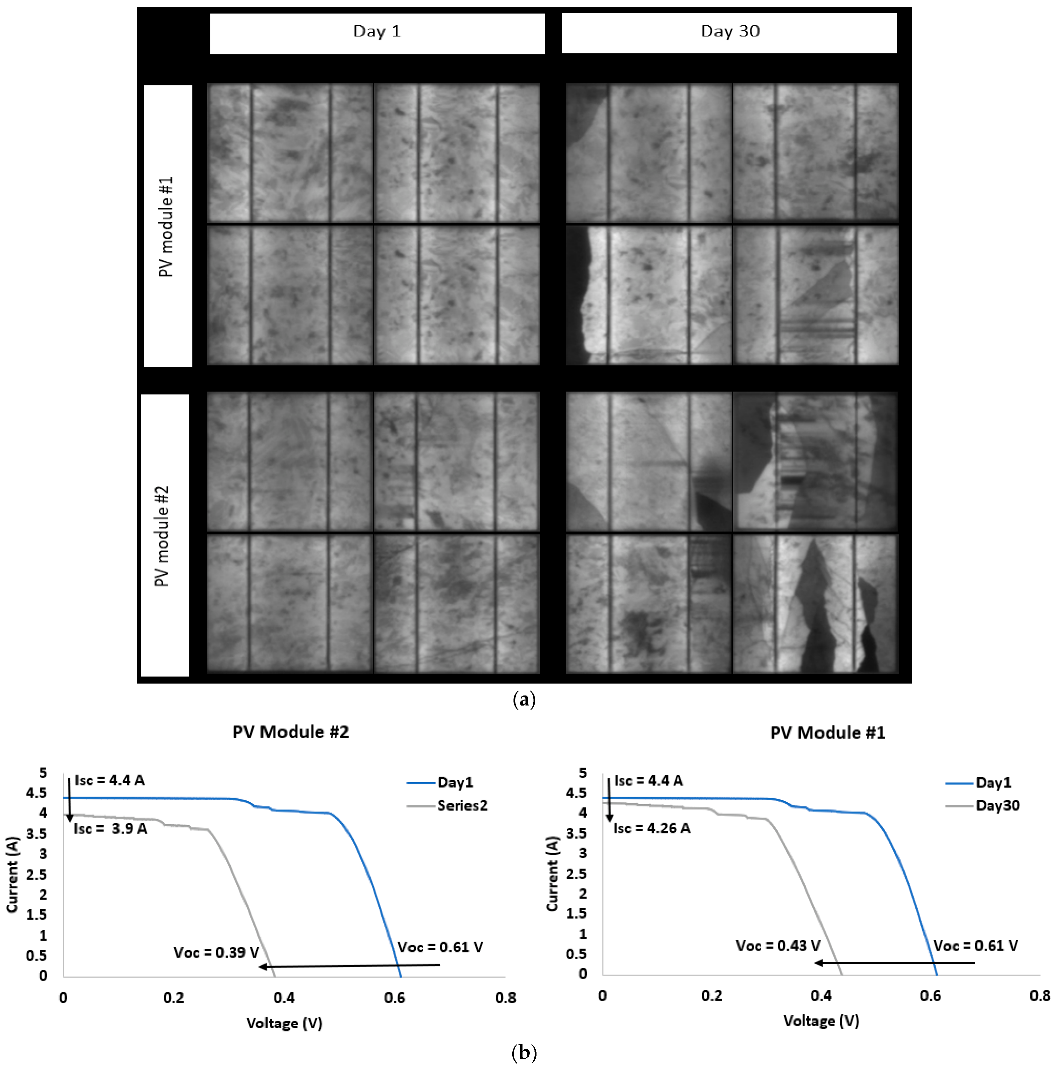
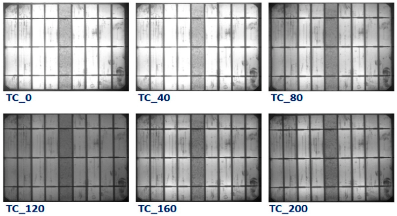
  • Based on a sample analysis of two PV modules in a solar road system, it has been found that the output power can degrade by at least 18% even in its first 30 days of operation without considering any coating device and sub-layer of the panels. The reason for this is due to the solar cells’ low resistance to heavy loads and continuous pressure causing massive cracking and breakdown. Hence, the surface of the road must be sufficiently rough to meet the requirements of skid resistance, while it must also be sufficiently smooth to allow good light transmission. Therefore, a balance should be made between the light transmission effect and skid resistance of the surface due to the apparent contradiction between skid resistance and light transmittance.
  • There are several factors that affect solar pavements’ ability to generate power, including location, climate, and uncertain factors such as environment and traffic. To adapt to changing operating conditions, further research can optimize solar pavement circuit designs based on the characteristics of the road environment, thereby increasing the flexibility of load management by enabling the solar pavements’ power generation to meet the demand of the load. Furthermore, appropriate energy storage technology can be developed to ensure that the solar pavements can meet the load demand. The cell coating elements also need to be backed up by appropriate circuit design.

Author Contributions

Conceptualization, S.H.; methodology, S.H. and M.D.; validation, M.D; formal analysis, S.H.; data curation, S.H. and M.D.; writing—original draft preparation, S.H.; writing—review and editing, M.D. All authors have read and agreed to the published version of the manuscript.

Funding

This research was funded by the University of York internal studentship fund under grant name “Practical Experimentation on the Deployment of Solar Roads”.

Conflicts of Interest

The authors declare no conflict of interest.

References

  1. De Jesus, M.A.M.L.; Timò, G.; Agustín-Sáenz, C.; Braceras, I.; Cornelli, M.; de Mello Ferreira, A. Anti-soiling coatings for solar cell cover glass: Climate and Surface Properties Influence. Sol. Energy Mater. Sol. Cells 2018, 185, 517–523. [Google Scholar] [CrossRef]
  2. Maghami, M.R.; Hizam, H.; Gomes, C.; Radzi, M.A.; Rezadad, M.I.; Hajighorbani, S. Power loss due to soiling on Solar Panel: A Review. Renew. Sustain. Energy Rev. 2016, 59, 1307–1316. [Google Scholar] [CrossRef] [Green Version]
  3. Khan, M.Z.; Ghaffar, A.; Bahattab, M.A.; Mirza, M.; Lange, K.; Abaalkheel, I.M.; Alqahtani, M.H.; Aldhuwaile, A.A.; Alqahtani, S.H.; Qasem, H.; et al. Outdoor performance of anti-soiling coatings in various climates of Saudi Arabia. Sol. Energy Mater. Sol. Cells 2022, 235, 111470. [Google Scholar] [CrossRef]
  4. Ilse, K.K.; Figgis, B.W.; Naumann, V.; Hagendorf, C.; Bagdahn, J. Fundamentals of soiling processes on photovoltaic modules. Renew. Sustain. Energy Rev. 2018, 98, 239–254. [Google Scholar] [CrossRef]
  5. Conceição, R.; González-Aguilar, J.; Merrouni, A.A.; Romero, M. Soiling effect in Solar Energy Conversion Systems: A Review. Renew. Sustain. Energy Rev. 2022, 162, 112434. [Google Scholar] [CrossRef]
  6. Birant, G.; de Wild, J.; Meuris, M.; Poortmans, J.; Vermang, B. Dielectric-Based Rear Surface Passivation Approaches for Cu(In,Ga)Se2 Solar Cells—A Review. Appl. Sci. 2019, 9, 677. [Google Scholar] [CrossRef] [Green Version]
  7. Romeo, A.; Artegiani, E. CdTe-Based Thin Film Solar Cells: Past, Present and Future. Energies 2021, 14, 1684. [Google Scholar] [CrossRef]
  8. Chu, Y.; Ho, C.; Lee, Y.; Li, B. Development of a Solar-Powered Unmanned Aerial Vehicle for Extended Flight Endurance. Drones 2021, 5, 44. [Google Scholar] [CrossRef]
  9. Salhi, B. The Photovoltaic Cell Based on CIGS: Principles and Technologies. Materials 2022, 15, 1908. [Google Scholar] [CrossRef]
  10. Ava, T.T.; Al Mamun, A.; Marsillac, S.; Namkoong, G. A Review: Thermal Stability of Methylammonium Lead Halide Based Perovskite Solar Cells. Appl. Sci. 2019, 9, 188. [Google Scholar] [CrossRef]
  11. Saadah, M.; Hernandez, E.; Balandin, A.A. Thermal Management of Concentrated Multi-Junction Solar Cells with Graphene-Enhanced Thermal Interface Materials. Appl. Sci. 2017, 7, 589. [Google Scholar] [CrossRef] [Green Version]
  12. Shi, Z.; Jayatissa, A.H. Perovskites-Based Solar Cells: A Review of Recent Progress, Materials and Processing Methods. Materials 2018, 11, 729. [Google Scholar] [CrossRef] [Green Version]
  13. Uddin, A.; Upama, M.B.; Yi, H.; Duan, L. Encapsulation of Organic and Perovskite Solar Cells: A Review. Coatings 2019, 9, 65. [Google Scholar] [CrossRef] [Green Version]
  14. Konstantakou, M.; Perganti, D.; Falaras, P.; Stergiopoulos, T. Anti-Solvent Crystallization Strategies for Highly Efficient Perovskite Solar Cells. Crystals 2017, 7, 291. [Google Scholar] [CrossRef] [Green Version]
  15. Kim, T.; Lim, J.; Song, S. Recent Progress and Challenges of Electron Transport Layers in Organic–Inorganic Perovskite Solar Cells. Energies 2020, 13, 5572. [Google Scholar] [CrossRef]
  16. Shaju, A.; Chacko, R. Soiling of photovoltaic modules—Review. In IOP Conference Series: Materials Science and Engineering; IOP Publishing: Bristol, UK, 2018; Volume 396, p. 012050. [Google Scholar]
  17. Laarabi, B.; El Baqqal, Y.; Rajasekar, N.; Barhdadi, A. Updated review on Soiling of Solar Photovoltaic Systems Morocco and India contributions. J. Clean. Prod. 2021, 311, 127608. [Google Scholar] [CrossRef]
  18. Jamil, W.J.; Abdul Rahman, H.; Shaari, S.; Salam, Z. Performance degradation of photovoltaic power system: Review on Mitigation Methods. Renew. Sustain. Energy Rev. 2017, 67, 876–891. [Google Scholar] [CrossRef]
  19. Miller, D.C.; Kurtz, S.R. Durability of fresnel lenses: A review specific to the concentrating photovoltaic application. Sol. Energy Mater. Sol. Cells 2011, 95, 2037–2068. [Google Scholar] [CrossRef]
  20. Kim, Y.; Wellum, G.; Mello, K.; Strawhecker, K.E.; Thoms, R.; Giaya, A.; Wyslouzil, B.E. Effects of relative humidity and particle and surface properties on particle resuspension rates. Aerosol Sci. Technol. 2016, 50, 339–352. [Google Scholar] [CrossRef] [Green Version]
  21. Said, S.A.M.; Walwil, H.M. Fundamental studies on dust fouling effects on PV module performance. Sol. Energy 2014, 107, 328–337. [Google Scholar] [CrossRef]
  22. Zaihidee, F.M.; Mekhilef, S.; Seyedmahmoudian, M.; Horan, B. Dust as an unalterable deteriorative factor affecting PV Panel’s efficiency: Why and how. Renew. Sustain. Energy Rev. 2016, 65, 1267–1278. [Google Scholar] [CrossRef]
  23. Appels, R.; Muthirayan, B.; Beerten, A.; Paesen, R.; Driesen, J.; Poortmans, J. The effect of dust deposition on photovoltaic modules. In Proceedings of the 2012 38th IEEE Photovoltaic Specialists Conference, Austin, TX, USA, 3–8 June 2012. [Google Scholar]
  24. Chiteka, K.; Arora, R.; Sridhara, S.N.; Enweremadu, C.C. Optimizing wind barrier and photovoltaic array configuration in soiling mitigation. Renew. Energy 2021, 163, 225–236. [Google Scholar] [CrossRef]
  25. Mekhilef, S.; Saidur, R.; Kamalisarvestani, M. Effect of dust, humidity and air velocity on efficiency of photovoltaic cells. Renew. Sustain. Energy Rev. 2012, 16, 2920–2925. [Google Scholar] [CrossRef]
  26. Ali, H.; Zafar, M.; Bashir, M.; Nasir, M.; Ali, M.; Siddiqui, A. Effect of dust deposition on the performance of photovoltaic modules in Taxila, Pakistan. Therm. Sci. 2017, 21, 915–923. [Google Scholar] [CrossRef]
  27. Tanesab, J.; Parlevliet, D.; Whale, J.; Urmee, T. The effect of dust with different morphologies on the performance degradation of photovoltaic modules. Sustain. Energy Technol. Assess. 2019, 31, 347–354. [Google Scholar] [CrossRef]
  28. Herman-Czezuch, A.; Mekeng, A.Z.; Meilinger, S.; Barry, J.; Kimiaie, N. Impact of aerosols on photovoltaic energy production using a spectrally resolved model chain: Case study of southern West Africa. Renew. Energy 2022, 194, 321–333. [Google Scholar] [CrossRef]
  29. Dumka, U.C.; Kosmopoulos, P.G.; Ningombam, S.S.; Masoom, A. Impact of Aerosol and Cloud on the Solar Energy Potential over the Central Gangetic Himalayan Region. Remote Sens. 2021, 13, 3248. [Google Scholar] [CrossRef]
  30. Valerino, M.; Ratnaparkhi, A.; Ghoroi, C.; Bergin, M. Seasonal photovoltaic soiling: Analysis of size and composition of deposited particulate matter. Sol. Energy 2021, 227, 44–55. [Google Scholar] [CrossRef]
  31. Einhorn, A.; Micheli, L.; Miller, D.C.; Simpson, L.J.; Moutinho, H.R.; To, B.; Lanaghan, C.L.; Muller, M.T.; Toth, S.; John, J.J.; et al. Evaluation of soiling and potential mitigation approaches on photovoltaic glass. IEEE J. Photovolt. 2018, 9, 233–239. [Google Scholar] [CrossRef]
  32. Sanz Saiz, C.; Polo Martínez, J.; Martín Chivelet, N. Influence of Pollen on Solar Photovoltaic Energy: Literature Review and Experimental Testing with Pollen. Appl. Sci. 2020, 10, 4733. [Google Scholar] [CrossRef]
  33. Said, S.A.M.; Hassan, G.; Walwil, H.M.; Al-Aqeeli, N. The effect of environmental factors and dust accumulation on photovoltaic modules and dust-accumulation mitigation strategies. Renew. Sustain. Energy Rev. 2018, 82, 743–760. [Google Scholar] [CrossRef]
  34. Majeed, R.; Waqas, A.; Sami, H.; Ali, M.; Shahzad, N. Experimental investigation of soiling losses and a novel cost-effective cleaning system for PV modules. Sol. Energy 2020, 201, 298–306. [Google Scholar] [CrossRef]
  35. Maindad, N.; Gadhave, A.; Satpute, S.; Nanda, B. Automatic Solar Panel Cleaning System. In Proceedings of the 2nd International Conference on Communication & Information Processing (ICCIP), Singapore, 26–29 November 2020. [Google Scholar]
  36. Sayyah, A.; Eriksen, R.S.; Horenstein, M.N.; Mazumder, M.K. Performance analysis of electrodynamic screens based on residual particle size distribution. IEEE J. Photovolt. 2017, 7, 221–229. [Google Scholar] [CrossRef]
  37. Dhimish, M.; Tyrrell, A.M. Power loss and hotspot analysis for photovoltaic modules affected by potential induced degradation. Npj Mater. Degrad. 2022, 6, 11. [Google Scholar] [CrossRef]
  38. Wette, J.; Fernández-García, A.; Sutter, F.; Buendía-Martínez, F.; Argüelles-Arízcun, D.; Azpitarte, I.; Pérez, G. Water saving in CSP plants by a novel hydrophilic anti-soiling coating for solar reflectors. Coatings 2019, 9, 739. [Google Scholar] [CrossRef] [Green Version]
  39. Conceição, R.; Silva, H.G.; Mirão, J.; Gostein, M.; Fialho, L.; Narvarte, L.; Collares-Pereira, M. Saharan dust transport to Europe and its impact on photovoltaic performance: A case study of soiling in Portugal. Sol. Energy 2018, 160, 94–102. [Google Scholar] [CrossRef]
  40. Wette, J.; Sutter, F.; Fernández-García, A. Evaluation of anti-soiling coatings for CSP reflectors under realistic outdoor conditions. Sol. Energy 2019, 191, 574–584. [Google Scholar] [CrossRef]
  41. Adak, D.; Bhattacharyya, R.; Barshilia, H.C. A state-of-the-art review on the multifunctional self-cleaning nanostructured coatings for PV panels, CSP mirrors and related solar devices. Renew. Sustain. Energy Rev. 2022, 159, 112145. [Google Scholar] [CrossRef]
  42. Lisco, F.; Bukhari, F.; Uličná, S.; Isbilir, K.; Barth, K.L.; Taylor, A.; Walls, J.M. Degradation of hydrophobic, anti-soiling coatings for Solar Module cover glass. Energies 2020, 13, 3811. [Google Scholar] [CrossRef]
  43. Hossain, M.I.; Ali, A.; Bermudez Benito, V.; Figgis, B.; Aïssa, B. Anti-Soiling Coatings for Enhancement of PV Panel Performance in Desert Environment: A Critical Review and Market Overview. Materials 2022, 15, 7139. [Google Scholar] [CrossRef]
  44. Oehler, G.C.; Lisco, F.; Bukhari, F.; Uličná, S.; Strauss, B.; Barth, K.L.; Walls, J.M. Testing the durability of anti-soiling coatings for solar cover glass by outdoor exposure in Denmark. Energies 2020, 13, 299. [Google Scholar] [CrossRef] [Green Version]
  45. Pei, J.; Zhou, B.; Lyu, L. E-road: The largest energy supply of the future? Appl. Energy 2019, 241, 174–183. [Google Scholar] [CrossRef]
  46. Dai, W.; Shi, B.; Li, T.; Goh, H.H.; Li, J. Power flow analysis considering solar road generation. Energy Rep. 2022, 8, 531–536. [Google Scholar] [CrossRef]
  47. Jia, L.; Ma, J.; Cheng, P.; Liu, Y. A perspective on solar energy-powered road and rail transportation in China. CSEE J. Power Energy Syst. 2020, 6, 760–771. [Google Scholar]
  48. Pillai, U. Drivers of cost reduction in solar photovoltaics. Energy Econ. 2015, 50, 286–293. [Google Scholar] [CrossRef]
  49. Xiang, B.; Cao, X.; Yuan, Y.; Sun, L.; Wu, H.; Haghighat, F. A novel hybrid energy system combined with solar-road and soil-regenerator: Dynamic model and operational performance. Energy Convers. Manag. 2018, 156, 376–387. [Google Scholar] [CrossRef] [Green Version]
  50. Kehagia, F.; Mirabella, S.; Psomopoulos, C.S. Solar pavement: A new source of energy. In Bituminous Mixtures and Pavements VII; CRC Press: Boca Raton, FL, USA, 2019; pp. 441–447. [Google Scholar]
  51. Prasanth, V.; Scheele, N.; Visser, E.; Shekhar, A.; Mouli, G.R.; Bauer, P.; Silvestser, S. Green energy based inductive self-healing highways of the future. In Proceedings of the 2016 IEEE Transportation Electrification Conference and Expo (ITEC), Dearborn, MI, USA, 27–29 June 2016. [Google Scholar]
  52. Dezfooli, A.S.; Nejad, F.M.; Zakeri, H.; Kazemifard, S. Solar pavement: A new emerging technology. Sol. Energy 2017, 149, 272–284. [Google Scholar] [CrossRef]
  53. Li, Y.; Zhang, J.; Cao, Y.; Hu, Q.; Guo, X. Design and evaluation of light-transmitting concrete (LTC) using waste tempered glass: A novel concrete for future Photovoltaic Road. Constr. Build. Mater. 2021, 280, 122551. [Google Scholar] [CrossRef]
  54. Hossain, M.F.; Dessouky, S.; Biten, A.B.; Montoya, A.; Fernandez, D. Harvesting solar energy from asphalt pavement. Sustainability 2021, 13, 12807. [Google Scholar] [CrossRef]
  55. Dhimish, M.; d’Alessandro, V.; Daliento, S. Investigating the impact of cracks on solar cells performance: Analysis based on nonuniform and uniform crack distributions. IEEE Trans. Ind. Inform. 2022, 18, 1684–1693. [Google Scholar] [CrossRef]
  56. Dhimish, M.; Mather, P. Development of novel Solar Cell Micro Crack Detection Technique. IEEE Trans. Semicond. Manuf. 2019, 32, 277–285. [Google Scholar] [CrossRef]
  57. Hilton, A.M.; Cahill, A.D.; Heller, E.R. A comparison of electroluminescence spectra from plan view and cross-sectioned Algan/Gan devices. IEEE Trans. Electron Devices 2018, 65, 59–63. [Google Scholar] [CrossRef]
  58. Dhimish, M.; Holmes, V.; Dales, M.; Mehrdadi, B. Effect of micro cracks on photovoltaic output power: Case study based on Real time long term data measurements. Micro Nano Lett. 2017, 12, 803–807. [Google Scholar] [CrossRef]
  59. Dhimish, M.; Mather, P. Ultrafast high-resolution solar cell cracks detection process. IEEE Trans. Ind. Inform. 2020, 16, 4769–4777. [Google Scholar] [CrossRef] [Green Version]
  60. Duru, R.; Le Cunff, D.; Cannac, M.; Mica, I.; Baruchel, J.; Tran-Thi, T.-N.; Bremond, G. Photoluminescence imaging for buried defects detection in silicon: Assessment and use-cases. IEEE Trans. Semicond. Manuf. 2019, 32, 23–30. [Google Scholar] [CrossRef]
  61. Nos, O.; Favre, W.; Jay, F.; Ozanne, F.; Valla, A.; Alvarez, J.; Muñoz, D.; Ribeyron, P.J. Quality Control method based on photoluminescence imaging for the performance prediction of C-Si/a-si:H heterojunction solar cells in industrial production lines. Sol. Energy Mater. Sol. Cells 2016, 144, 210–220. [Google Scholar] [CrossRef]
  62. Bhoopathy, R.; Kunz, O.; Juhl, M.; Trupke, T.; Hameiri, Z. Outdoor photoluminescence imaging of photovoltaic modules with Sunlight Excitation. Prog. Photovolt. Res. Appl. 2017, 26, 69–73. [Google Scholar] [CrossRef]
  63. Dhimish, M. Thermal impact on the performance ratio of photovoltaic systems: A case study of 8000 photovoltaic installations. Case Stud. Therm. Eng. 2020, 21, 100693. [Google Scholar] [CrossRef]
  64. Henry, C.; Poudel, S.; Lee, S.-W.; Jeong, H. Automatic detection system of deteriorated PV modules using drone with Thermal camera. Appl. Sci. 2020, 10, 3802. [Google Scholar] [CrossRef]
  65. Zhang, P.; Zhang, L.; Wu, T.; Zhang, H.; Sun, X. Detection and location of fouling on photovoltaic panels using a drone-mounted infrared thermography system. J. Appl. Remote Sens. 2017, 11, 016026. [Google Scholar] [CrossRef]
  66. Alsafasfeh, M.; Abdel-Qader, I.; Bazuin, B.; Alsafasfeh, Q.; Su, W. Unsupervised fault detection and analysis for large photovoltaic systems using drones and Machine Vision. Energies 2018, 11, 2252. [Google Scholar] [CrossRef]
  67. Khan, F.; Rezgui, B.D.; Kim, J.H. Reliability Study of c-Si PV Module Mounted on a Concrete Slab by Thermal Cycling Using Electroluminescence Scanning: Application in Future Solar Roadways. Materials 2020, 13, 470. [Google Scholar] [CrossRef] [PubMed] [Green Version]
  68. Khan, F.; Kim, J.H. Performance degradation analysis of C-si PV modules mounted on a concrete slab under hot-humid conditions using electroluminescence scanning technique for potential utilization in future solar roadways. Materials 2019, 12, 4047. [Google Scholar] [CrossRef] [PubMed] [Green Version]
  69. Hu, H.; Zha, X.; Li, Z.; Lv, R. Preparation and performance study of solar pavement panel based on transparent resin-concrete. Sustain. Energy Technol. Assess. 2022, 52, 102169. [Google Scholar] [CrossRef]
  70. Le Touz, N.; Dumoulin, J.; Piau, J.-M. Multi-physics FEM model of solar hybrid roads for energy harvesting performance evaluation in presence of semi-transparent or opaque pavement surface layer. In International Heat Transfer Conference Digital Library; Begel House Inc.: Danbury, CT, USA, 2018. [Google Scholar]
  71. Vizzari, D.; Chailleux, E.; Gennesseaux, E.; Lavaud, S.; Vignard, N. Viscoelastic characterisation of transparent binders for application on Solar Roads. Road Mater. Pavement Des. 2019, 20, S112–S126. [Google Scholar] [CrossRef]
  72. Settou, B.; Settou, N.; Gouareh, A.; Negrou, B.; Mokhtara, C.; Messaoudi, D. GIS-based method for future prospect of energy supply in Algerian road transport sector using Solar Roads Technology. Energy Procedia 2019, 162, 221–230. [Google Scholar] [CrossRef]
  73. Liu, Z.; Fei, T. Road PV production estimation at City Scale: A predictive model towards feasible assessing regional energy generation from Solar Roads. J. Clean. Prod. 2021, 321, 129010. [Google Scholar] [CrossRef]
  74. Lee, K.; Cho, S.B.; Yi, J.; Chang, H.S. Simplified recovery process for resistive solder bond (RSB) hotspots caused by poor soldering of crystalline silicon photovoltaic modules using resin. Energies 2022, 15, 4623. [Google Scholar] [CrossRef]
  75. Lopes, D.; Conceição, R.; Silva, H.G.; Aranzabe, E.; Pérez, G.; Collares-Pereira, M. Anti-soiling coating performance assessment on the reduction of soiling effect in second-surface solar mirror. Sol. Energy 2019, 194, 478–484. [Google Scholar] [CrossRef]
  76. Zhang, J.; Ai, L.; Lin, S.; Lan, P.; Lu, Y.; Dai, N.; Tan, R.; Fan, B.; Song, W. Preparation of humidity, abrasion, and dust resistant antireflection coatings for photovoltaic modules via dual precursor modification and hybridization of hollow silica nanospheres. Sol. Energy Mater. Sol. Cells 2019, 192, 188–196. [Google Scholar] [CrossRef]
  77. Joshi, D.N.; Atchuta, S.R.; Lokeswara Reddy, Y.; Naveen Kumar, A.; Sakthivel, S. Super-hydrophilic broadband anti-reflective coating with high weather stability for solar and optical applications. Sol. Energy Mater. Sol. Cells 2019, 200, 110023. [Google Scholar] [CrossRef]
  78. Sutha, S.; Suresh, S.; Raj, B.; Ravi, K.R. Transparent alumina based superhydrophobic self–cleaning coatings for solar cell cover glass applications. Sol. Energy Mater. Sol. Cells 2017, 165, 128–137. [Google Scholar] [CrossRef]
  79. Marchand, D.J.; Dilworth, Z.R.; Stauffer, R.J.; Hsiao, E.; Kim, J.-H.; Kang, J.-G.; Kim, S.H. Atmospheric RF plasma deposition of superhydrophobic coatings using tetramethylsilane precursor. Surf. Coat. Technol. 2013, 234, 14–20. [Google Scholar] [CrossRef]
  80. Bosch-Jimenez, P.; Martínez, M.; Hipólito, Á.; Rubia, O.D.L.; Pirriera, M.D.; Cantos, B.; Álvarez, A. NODUSTPV project: Development and testing of anti-soiling coatings. In AIP Conference Proceedings; AIP Publishing LLC: Melville, NY, USA, 2018; p. 020002. [Google Scholar]
  81. Sagar, R.; Rao, A. Nanoscale tio2 and TA2O5 as efficient antireflection coatings on commercial monocrystalline silicon solar cell. J. Alloys Compd. 2021, 862, 158464. [Google Scholar] [CrossRef]
  82. Ekinci, S.Y.; Sancakli, S.; Adam, L.A.W.; Walls, J.M. Performance and durability of thin film solar cells via testing the abrasion resistance of broadband anti-reflection coatings. J. Energy Syst. 2022, 6, 33–45. [Google Scholar] [CrossRef]
  83. Shah, D.K.; KC, D.; Umar, A.; Algadi, H.; Akhtar, M.S.; Yang, O.-B. Influence of efficient thickness of antireflection coating layer of HFO2 for crystalline silicon solar cell. Inorganics 2022, 10, 171. [Google Scholar] [CrossRef]
  84. Makableh, Y.F.; Vasan, R.; Sarker, J.C.; Nusir, A.I.; Seal, S.; Manasreh, M.O. Enhancement of gaas solar cell performance by using a zno sol–gel anti-reflection coating. Sol. Energy Mater. Sol. Cells 2014, 123, 178–182. [Google Scholar] [CrossRef]
  85. Makableh, Y.F.; Al-Fandi, M.; Khasawneh, M.; Tavares, C.J. Comprehensive design analysis of zno anti-reflection nanostructures for SI solar cells. Superlattices Microstruct. 2018, 124, 1–9. [Google Scholar]
  86. Juhász Junger, I.; Wehlage, D.; Böttjer, R.; Grothe, T.; Juhász, L.; Grassmann, C.; Blachowicz, T.; Ehrmann, A. Dye-Sensitized Solar Cells with Electrospun Nanofiber Mat-Based Counter Electrodes. Materials 2018, 11, 1604. [Google Scholar] [CrossRef] [Green Version]
  87. Višniakov, J.; Janulevičius, A.; Maneikis, A.; Matulaitienė, I.; Selskis, A.; Stanionytė, S.; Suchodolskis, A. Antireflection tio2 coatings on textured surface grown by HiPIMS. Thin Solid Film. 2017, 628, 190–195. [Google Scholar] [CrossRef]
  88. Pendse, S.; Chandra Sekhar Reddy, K.; Narendra, C.; Murugan, K.; Sakthivel, S. Dual-functional broadband antireflective and hydrophobic films for solar and optical applications. Sol. Energy 2018, 163, 425–433. [Google Scholar] [CrossRef]
  89. Shin, B.-K.; Lee, T.-I.; Xiong, J.; Hwang, C.; Noh, G.; Cho, J.-H.; Myoung, J.-M. Bottom-up grown zno nanorods for an antireflective moth-eye structure on Cuingase2 Solar Cells. Sol. Energy Mater. Sol. Cells 2011, 95, 2650–2654. [Google Scholar] [CrossRef]
  90. Makableh, Y.F.; Alzubi, H.; Tashtoush, G. Design and Optimization of the Antireflective Coating Properties of Silicon Solar Cells by Using Response Surface Methodology. Coatings 2021, 11, 721. [Google Scholar] [CrossRef]
  91. Xie, H.; Huang, H.-X.; Peng, Y.-J. Rapid fabrication of bio-inspired nanostructure with hydrophobicity and antireflectivity on polystyrene surface replicating from Cicada Wings. Nanoscale 2017, 9, 11951–11958. [Google Scholar] [CrossRef] [PubMed]
  92. Tao, C.; Zou, X.; Du, K.; Zhou, G.; Yan, H.; Yuan, X.; Zhang, L. Fabrication of robust, self-cleaning, broadband tio2sio2 double-layer antireflective coatings with closed-pore structure through a surface sol-gel process. J. Alloys Compd. 2018, 747, 43–49. [Google Scholar] [CrossRef]
  93. Zhou, B.; Pei, J.; Xue, B.; Guo, F.; Wen, Y.; Zhang, J.; Li, R. Solar/Road from ‘forced coexistence’ to ‘harmonious symbiosis’. Appl. Energy 2019, 255, 113808. [Google Scholar] [CrossRef]
  94. Shekhar, A.; Kumaravel, V.K.; Klerks, S.; de Wit, S.; Venugopal, P.; Narayan, N.; Bauer, P.; Isabella, O.; Zeman, M. Harvesting roadway solar energy—Performance of the installed infrastructure integrated PV Bike Path. IEEE J. Photovolt. 2018, 8, 1066–1073. [Google Scholar] [CrossRef]
  95. Vizzari, D.; Chailleux, E.; Lavaud, S.; Gennesseaux, E.; Bouron, S. Fraction factorial design of a novel semi-transparent layer for applications on Solar Roads. Infrastructures 2020, 5, 5. [Google Scholar] [CrossRef] [Green Version]
  96. Wu, L.; Yuan, Y.; Wu, H. Solar Road Power Generation Assessment based on coupled transportation and Power Distribution Systems. J. Phys. Conf. Ser. 2020, 1659, 012041. [Google Scholar] [CrossRef]
  97. Vincent, J. The Solar Roadway is Getting a (Tiny) Test Along Route 66. Available online: https://www.theverge.com/2016/7/1/12077414/solar-panel-roadway-public-test-route-66 (accessed on 15 November 2022).
  98. Calì, M.; Hajji, B.; Nitto, G.; Acri, A. The Design Value for Recycling End-of-Life Photovoltaic Panels. Appl. Sci. 2022, 12, 9092. [Google Scholar] [CrossRef]
  99. Kim, S.-H.; Baek, S.-C.; Choi, K.-B.; Park, S.-J. Design and Installation of 500-kW Floating Photovoltaic Structures Using High-Durability Steel. Energies 2020, 13, 4996. [Google Scholar] [CrossRef]
  100. Kudelas, D.; Taušová, M.; Tauš, P.; Gabániová, Ľ.; Koščo, J. Investigation of Operating Parameters and Degradation of Photovoltaic Panels in a Photovoltaic Power Plant. Energies 2019, 12, 3631. [Google Scholar] [CrossRef]
  101. Alamri, H.R.; Rezk, H.; Abd-Elbary, H.; Ziedan, H.A.; Elnozahy, A. Experimental Investigation to Improve the Energy Efficiency of Solar PV Panels Using Hydrophobic SiO2 Nanomaterial. Coatings 2020, 10, 503. [Google Scholar] [CrossRef]
  102. Bukowski, M.; Majewski, J.; Sobolewska, A. Macroeconomic Electric Energy Production Efficiency of Photovoltaic Panels in Single-Family Homes in Poland. Energies 2021, 14, 126. [Google Scholar] [CrossRef]
Figure 1. PV system after one month of soiling at the Qatari QEERI Solar Test Facility [4].
Energies 15 09620 g001
Figure 2. Impact of the angle of incidence on a soiled module [17].
Energies 15 09620 g002
Figure 3. Robotic cleaning examples [5]: (a) GEKKO, from SEBROT AG; (b) SunPower Oasis, from SUNPOWER company; (c) HECTOR, from SENER company; (d) PARIS from SENER company.
Energies 15 09620 g003
Figure 4. The working principle of electrodynamic screen [17].
Energies 15 09620 g004
Figure 5. Coating mode of action: (Left) hydrophobic; (Right) hydrophilic, presented by [5].
Energies 15 09620 g005
Figure 6. Schematic of some of the important sol-gel processes leading to various type of films/coatings [41].
Energies 15 09620 g006
Figure 7. SEM images of as-received coupons with A in: (a) planar view revealing surface defects and (b) cross-sectional view showing the presence of voids, and B in (c) planar view, (d) cross-sectional view showing no defect [44].
Energies 15 09620 g007
Figure 8. Summary of key challenges of PV anti-soiling methods.
Energies 15 09620 g008
Figure 9. Schematic diagram of the pavement solar box [54].
Energies 15 09620 g009
Figure 10. Solar cell inspected under three different industrial inspection methods: (a) EL, (b) PL, (c) thermal.
Energies 15 09620 g010
Figure 11. PV solar road tested in a public path at the University of York: (a) Picture of the solar panels, (b) EL imaging setup.
Energies 15 09620 g011
Figure 12. PV solar road: (a) Obtained EL images of the solar panels on day 1 and after 30 days of installation. The EL images were taken during night-time at short-circuit conditions, and the irradiance level at 0 W/m2 and the temperature at 16.3 °C, (b) Measured I–V curve for both PV modules.
Energies 15 09620 g012
Figure 13. Optical image of photovoltaic (PV) modules inside the thermal cycling chamber [67].
Energies 15 09620 g013
Figure 14. EL images of PV modules without concrete after various thermal cycling tests (0, 40, 80, 120, 160, and 200 cycles) [67].
Energies 15 09620 g014
Figure 15. EL images of PV modules with concrete after various thermal cycling tests (0, 40, 80, 120, 160, and 200 cycles) [67].
Energies 15 09620 g015
Figure 16. Thermal vs EL images of PV module affected by inactive bypass diode. PV module test: (A) Thermal vs EL images of PV module affected by inactive bypass diode, (B) Procedure for soldering and bypass diode fixing proposed by [74], the process as shown in the figure is as follows, (a) to accurately mark the punch location on the RSB hotspot part, shine a light source from the bottom of the part, (b) remove the back sheet and EVA of the part using a specially manufactured iron, (c) use tweezers to remove the carbonized EVA around the bus bar and the interconnector ribbon, and ensure that it is sufficiently dry at room temperature, (d) apply flux and re-solder the area using additional solder, and remove the solder smoke. Instead of using the lamination process, fill the re-soldering part and the part from which the EVA was removed with a silicon resin to insulate the soldering part, (e) allow the resin to dry at room temperature in a well-ventilated place to remove the organic solvent, (f) apply a sealant for the PV module to the junction box of the PV module and the insulation inside the box, and finish with tape made of the same material as the back sheet.
Energies 15 09620 g016aEnergies 15 09620 g016b
Figure 17. Materials selection: (a) currently available anti-soiling materials [75,76,77,78,79,80], (b) currently available anti-reflecting materials [81,82,83,84,85,86].
Energies 15 09620 g017
Table 1. Comparison of various ASC/ARC coatings.
ASC/ARC MaterailReflectance %TransmitanceFeasibility and Cost-EffectivenessDurabilityReferences
TiO2Less than 3As-yet unkownCost-effective, manufacturing in large scaleAs-yet unkown[87]
MgF2As-yet unkown97.03Cost-effective method and simple techniqueMechanically and environmentally stable[88]
ZnO1.4As-yet unkownLab-preparable and cheapAs-yet unkown[89,90]
Polystyrene4As-yet unkownEfficacious and rapid fabricatiomAs-yet unkown[91]
SiO2 and TiO2 (double layer)As-yet unkown97.7Durable and resitve against temperature andFacile and simple fabrication[92]
Table 2. Summary of currently available solar roads.
YearLocation and AreaCostMaterialImage of PV SetupReferences
201470 m long and 2 m wide in Krommenie, North Holland, The Netherlands£1,300,000A 1 cm thick layer of thick glass is placed on top of fabricated slabs
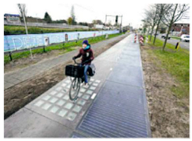
Energies 15 09620 i001[93,94]
2016Road in the countryside, Normandy, France, 1 km£4,300,000Polymers and resins coat the cells, making them transparent and resistant to traffic.Energies 15 09620 i002[93,95]
2017≈1.1 km in Jinan, China£4,650,000The top is concrete permeable to light, the middle is thin amorphous silicon panels, and the bottom is waterproof insulate.Energies 15 09620 i003[93,96]
Publisher’s Note: MDPI stays neutral with regard to jurisdictional claims in published maps and institutional affiliations.

