Abstract
This paper proposes an operation methodology for interfacing synchronous generator and energy storage system (ESS) by replacing conventional governor. This research introduces energy management scheme with droop control method for frequency regulation in coordination with synchronous generator. For frequency regulation, generator can take advantage of the ESS instead of the governor, with its relatively fast characteristics, leading to less frequent deviation of synchronous generator. For the verification, we simulate a network reduction model from real Korean network data, based on the case studies using PSCAD/EMTDC software.
1. Introduction
For stable operation under high penetration, a large number of utilities employ energy storage system to maintain consistent stability, which involves balancing the consumption and generation [1,2,3,4,5,6]. Several previous studies show that the high penetration of renewable energy sources (RES) reduces the number of synchronous generators, and the generation variability from RES affects primary and secondary frequency control. In this regard, an energy storage system (ESS) can be a countermeasure of the frequency regulation (FR) reinforcement for the power system [7,8,9,10]. Especially, several control method such as droop control, automatic generation control (AGC) including state of charge (SOC) feedback control, and autonomously activating power control assist with frequency regulation [11,12,13] by improving the response time using faster-acting ESS [14,15]. The fluctuating renewable sources, such as wind power fluctuation, have less impact on frequency stability thanks to help from storage devices that smooth the renewable intermittency [16,17].
As ESS has the nature of limited energy, various energy management schemes such as SOC feedback method were developed [14,18]. The droop set point adjustment method as a load frequency control (LFC) was also introduced [19], and the SOC management for the reserves with penalty functions was introduced [20]. As for the droop control for frequency regulation, the adaptive droop control considering SOC is explored [21,22]. Besides, battery energy storage systems (BESS) are widely utilized to provide a flexible energy management solution [23,24,25,26]. An operation control method of two forms of storage for managing state-of-charge (SOC), such as supercapacitor and ESS, for charging/discharging the battery for ancillary service concerning frequency regulation was studied, with a guideline for storage sizing based on the smoothing time constant of supercapacitor and ESS [27]. Previous research showed how to improve the smoothing PV power and regulate the voltage, and the paper focuses on the new application of superconducting coil (SC), which is integrated into the photovoltaic (PV) generator [28]. In this research, the SC is connected to the DC side of the PV generator via a DC-to-DC converter [28]. The technical report on IEEE Power and Energy Society [29] showed the dynamic model of turbine-governor and conventional generator for the power system simulations. The critical vision of the report was to show the contribution of the turbine-governor model in the power system studies, which deals mainly with transient angle and voltage stability, small-signal stability, and frequency control and stability. In this regard, the modeling of the turbine governor is crucial to frequency response of a power system. A previous work showed that the dynamic operation of the AGC is essential to the power grid frequency adjustment, and the evaluation indexes and calculation methods are provided for the step/continuous load disturbances control [30]. A study for improving system frequency in power-electronics-dominated grid was carried out [31]. This work presents a predictive control strategy to enable robust and stable functioning of the power electronics for distributed generation systems (PEDG) in response to load and generation disturbances by simulating virtual inertia. Moreover, it showed the possibility of eliminating the need for cascaded linear control and employed a model predictive control (MPC) that enables virtual inertia emulation [31]. The network operator in South Korea, named Korea Electric Power Corporation (KEPCO), employs the ESS algorithm introduced in [32,33,34], and this algorithm is now practically applied with the large number of batteries in the network of KEPCO. By backing up battery manufacturers, the Korean government still has the greatest number of ESS installation plans to accommodate the high penetration level of renewable sources.
Against this backdrop, we started this research project among generation company, generation plant manufacturer, and academia, aiming at elimination of the reserve cost during the generator operation, and this reserve-less operation can be implemented by interfacing ESS with the synchronous generator and replacing conventional governor. As the reserve of synchronous generator is reduced, operation cost can be significantly reduced since less fuel is required; however, we, in this study, focus on the advantage from the view point of dynamics characteristics of the generator. Although not much research was carried out combining large-scale synchronous generator and ESS, we found that uncountable advantages exist in this research topic.
Thus, this article shows the advantage of ESS replacing governor (Governing ESS) on the generator from a perspective of SOC management scheme and frequency regulation performance.
2. Conventional Generator Modeling
In the large power network, the dynamic characteristics of the generator appear as a change of generator frequency resulting from the deviation of mechanical and electrical torque. This characteristics are related to swing equation including the moment of inertia (J) and damping ratio (D). The change of electrical () or mechanical torque () is directly related with generator angular speed, and both torques can control the generator frequency, i.e., mechanical torque can be adjusted by governor, while electrical torque can be adjusted by ESS. The physical phenomenon as the equation of motion can be expressed in (1).
where J is the moment of inertia, is the angular velocity, D is the damping coefficient of Generator, is the mechanical power of Generator, and is the mechanical power of Generator.
The objective of primary droop control is to stabilize the network and accomplish a sharing of load in parallel among the large number of the generators [35].
Droop control in the generator adjusts generator output power in response to the change of grid frequency. This control can be accomplished by adjusting mechanical power of the generator along the droop rate in (2) based on the rotation speed, and the equation can be expressed as (3). The mechanical torque is regulated by a governor that drives a synchronous generator connected to the power grid, which is used as a speed control according to the equation of motion as in (4), as Figure 1 shows the relationship between the frequency and the active power.
where is the droop rate of generator, is the rotor speed deviation, is nominal angular speed in the grid, is the active power change from governor, stands for the rated power of generator, is mechanical power, is initial mechanical power, is angular speed of the generator, is rated angular speed of the generator, and is electrical power.
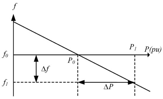
Figure 1.
Conceptual illustration of droop curve.
3. Proposed Control Method for Conventional Generator and ESS
In this paper, we propose the method for the generator angular speed regulation using ESS instead of the governor, although the governor traditionally regulates the angular speed of the synchronous generator. In other words, ESS takes droop control to achieve better performance than governor for the generator frequency regulation by replacing governor.
If this configuration (Generator and ESS interface) is employed, rapid support of the power can be performed in response to the grid frequency deviation to stably operate the power system.
In case of governor as in Figure 2a, the generator speed regulation response of the governor is comparatively slow due to the mechanical response of the governor. The mechanical control of governor action becomes the valve adjustment, which controls the quantity of the steam from the boiler to the generator through the valve to control generator speed. In the ESS case, ESS can be characterized as fast action as the power converter is employed; however, ESS has finite energy, and SOC must be properly adjusted to overcome this drawback.
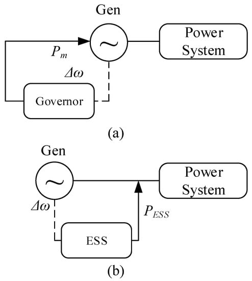
Figure 2.
Comparison between conventional and proposed FR. (a) conventional FR method with governor; (b) proposed method of FR ESS instead of governor.
3.1. Proposed Droop Control of ESS Replacing Governor for Generator Frequency Regulation
In proposed method of Figure 2b, the generator can take advantage of ESS’s faster action. Typically, due to a slow response from the turbine-governor operation, the slowly matching mechanical and electrical power leads to the fast change of the frequency. As a viewpoint of ESS, the frequency deviation becomes the inputs of ESS; subsequently, ESS carries out the droop control as in (6) by adjusting the electrical power to balance generator’s mechanical and electrical power. This results in the identical equation with generator droop control as explained in (4).
where is electrical power of generator, is initial electrical power of generator, is the droop rate of generator, is the droop rate of ESS satisfying generator droop rate, is the angular speed deviation of generator in pu, is the differences between mechanical and electrical power generator in pu, is the ESS converter rating, and is the generator rating.
Typically, the conventional governor receives the angular velocity signal of the generator rotor. The governor can be considered as the internal controller incorporating slow mechanical dynamics for adjusting the mechanical power. In this paper, we proposed a method with the external control, which is now controlling the ESS instead of using the internal control for the generator. When the event occurs in the power system and the outgoing electrical power from the generator changes, the ESS in proposed method provides the electric power by managing generator speed, although governor in previous method adjusts the mechanical power to manage generator speed. The proposed coordinated control method potentially assists with balancing the fluctuating power from the renewable source in the network under the high-penetration system.
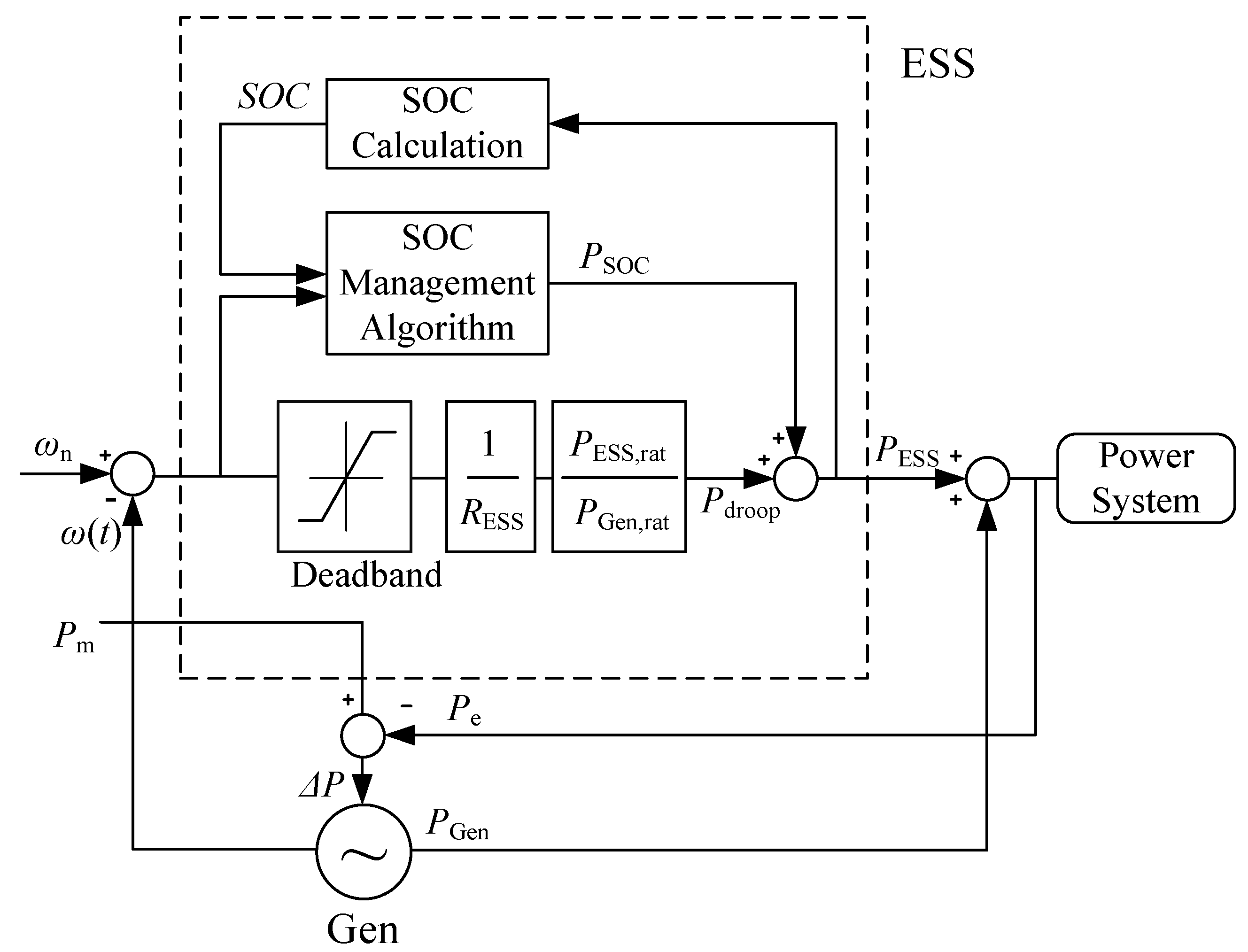
The proposed method of ESS on generation plant is shown in Figure 3. In this configuration, as ESS replaces the governor, ESS receives the generator angular speed (), which goes into droop control block () and generates the signal. For the SOC management, after SOC calculation [7,36,37], SOC signal (SOC) and angular speed deviation () are required for operation of the SOC management scheme. Those outputs for SOC management () and frequency regulation () becomes the total output of ESS () as in Figure 3.
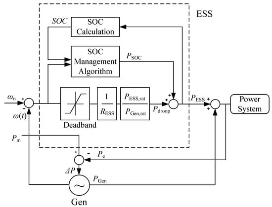
Figure 3.
Proposed ESS operation method for FR and SOC management interfacing with synchronous generator.
The ESS output () has an influence on generator electrical power (); subsequently, this algorithm controls the speed of the generator to regulate synchronous generator.
As this ESS droop control assists generator speed regulation, the droop control (normally under 5%) should be set in the view point of generator rating; in other words, if ESS would control with this droop rate, the droop rate should be set with ESS rating in (5). In this configuration, ESS operates well with low droop rate, as this method uses the clear mechanical angular speed directly from generator without the fast change, due to the three-phase imbalance and the high inertial energy in the generator.
3.2. SOC Management Strategy
A lithium-ion (Li-ion) is properly suited for the proposed control method, which is also the one of the most widely used storage applications among attery types due to its characteristics of fast response and high power capability in timescales from seconds to minutes [38,39,40].
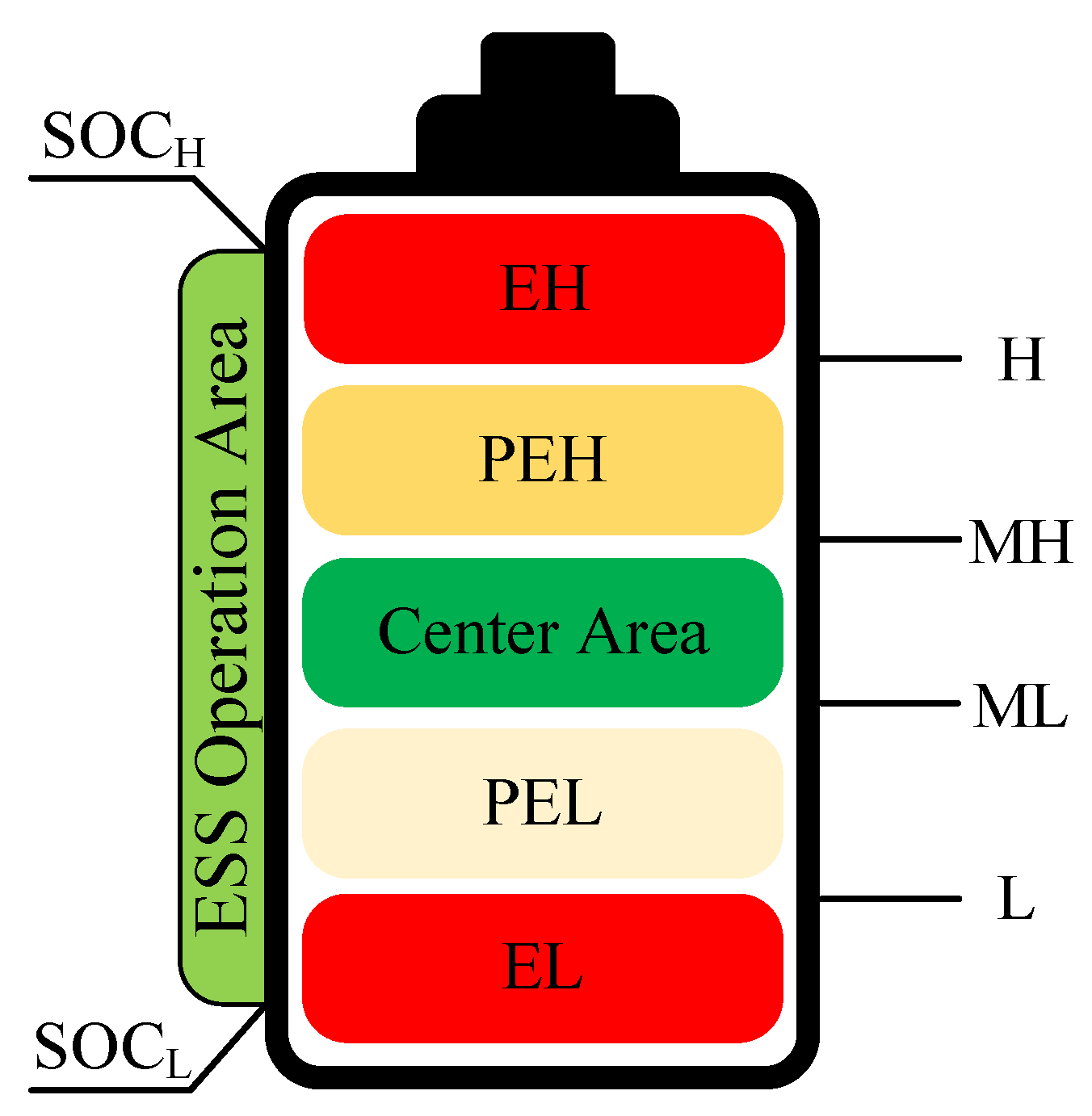
In this study, the SOC of the battery is divided into five states of operation, as shown in Figure 4. The SOC management algorithm is designed to settle down in the center of SOC where ESS can easily charge or discharge in accordance with the grid frequency, named the Center Area. In case SOC becomes slightly higher than this Center Area, we make the state of the battery enter into its pre-emergency high (PEH) state, which happens when it exceeds a SOC value of medium-high (MH). In this state, ESS tries to discharge for the management of SOC (i.g., reducing SOC), which is a relatively small amount of power, compared to that of the higher SOC case. When the SOC rises in the PEH state and exceeds the high value (H), the state of the battery reaches emergency high (EH). In this state, ESS also intends to reduce the SOC value and discharge the higher power than the power in PEH toward Center Area. In case the SOC value drops under the medium low (ML) value, the state of the battery becomes pre-emergency low (PEL). In this state, the battery tries to charge to increase the SOC to approach Center Area. If the SOC decreases further and cross the low value (L), the state of the battery reaches the emergency low (EL), where the battery has to be charged [34].
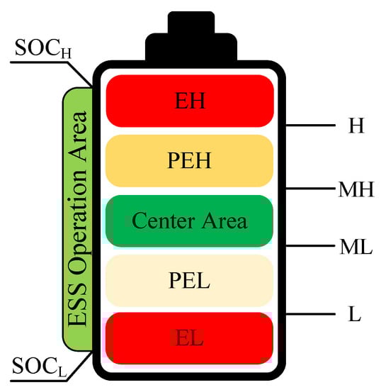
Figure 4.
SOC sections for management strategy.
3.3. Implementation of Frequency Control with SOC Management
As shown in Figure 5, the power of ESS is basically determined by SOC and generator angular speed status. When the speed deviation occurs and crosses the dead-band, the control mode turns into droop control. In this case, the power value for SOC management () is fixed as an initial value at droop activation.
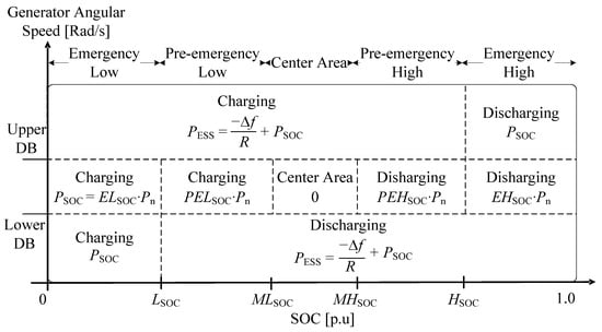
Figure 5.
Algorithm table for ESS power determination based on angular speed (Gen.) and SOC (ESS).
If SOC is located at a high value and not much capacity remains for charging, the droop control is deactivated when SOC crosses the value of high SOC (). Likewise, if SOC is located at a low value and discharging capacity does not remains enough, the droop control is also deactivated when SOC decreases under the value of low SOC ().
In case the generator angular speed is located within the dead-band in Figure 5, SOC management scheme operates as the power discharges or charges when SOC is high or low, respectively. The coefficient lower than one is multiplied with the rated capacity based on the SOC deviation if , , , or are within the dead-band range. The discharging quantity at EH is set to discharge 15% of the converter rating (), and this value is determined with the (0.15) to multiply on , and PEH is set to discharge 10% of the converter rating () as the coefficient (0.10). Likewise, in the case of EL, the amount to be charged is 15% of the converter rating () with the coefficient , and in the case of PEL the charging amount is set as 10% of the converter rating, and this value is named in this research.
where is the active power of ESS, is the rated value of ESS power conversion system (PCS), is the initial power of ESS in case droop control is activated, is the generator angular speed, is the upper limit of dead-band (droop activation speed in upper side), is the lower limit of dead-band (droop activation speed in lower side), is the droop rate, is the measured SOC value, is the coefficient for SOC management in emergency high (EH) area, is the coefficient for SOC management in pre-emergency high (PEH) area, is the coefficient for SOC management in pre-emergency low (PEL) area, is the coefficient for SOC management in emergency low (EL) area, is the SOC point to distinguish high SOC, is the SOC point to distinguish medium-high SOC, is the SOC point to distinguish medium-low SOC, and is the SOC point to distinguish low SOC.
The ESS power can be determined with the conditions of SOC and generator speed in (7), (8) for FR and SOC management. As in (7), (8) and Figure 5, if the SOC value is lower than the value of low SOC (), a coefficient of is multiplied to the rated power of PCS, and in case the value is located between low SOC and medium-low SOC (), the coefficient is multiplied by the rated power of PCS. Similarly, if the SOC is higher than the value of high SOC (), a coefficient of is multiplied to by the rated power of PCS, and if the SOC is positioned between medium-high SOC and high SOC (), a coefficient of is multiplied. These operating conditions can be summarized mathematically as in (7) and (8), and if no frequency event occurs during the SOC management, the scheme of SOC management is designed to ultimately be located in the Center Area.
3.3.1. State Transition Analysis Using State Machine
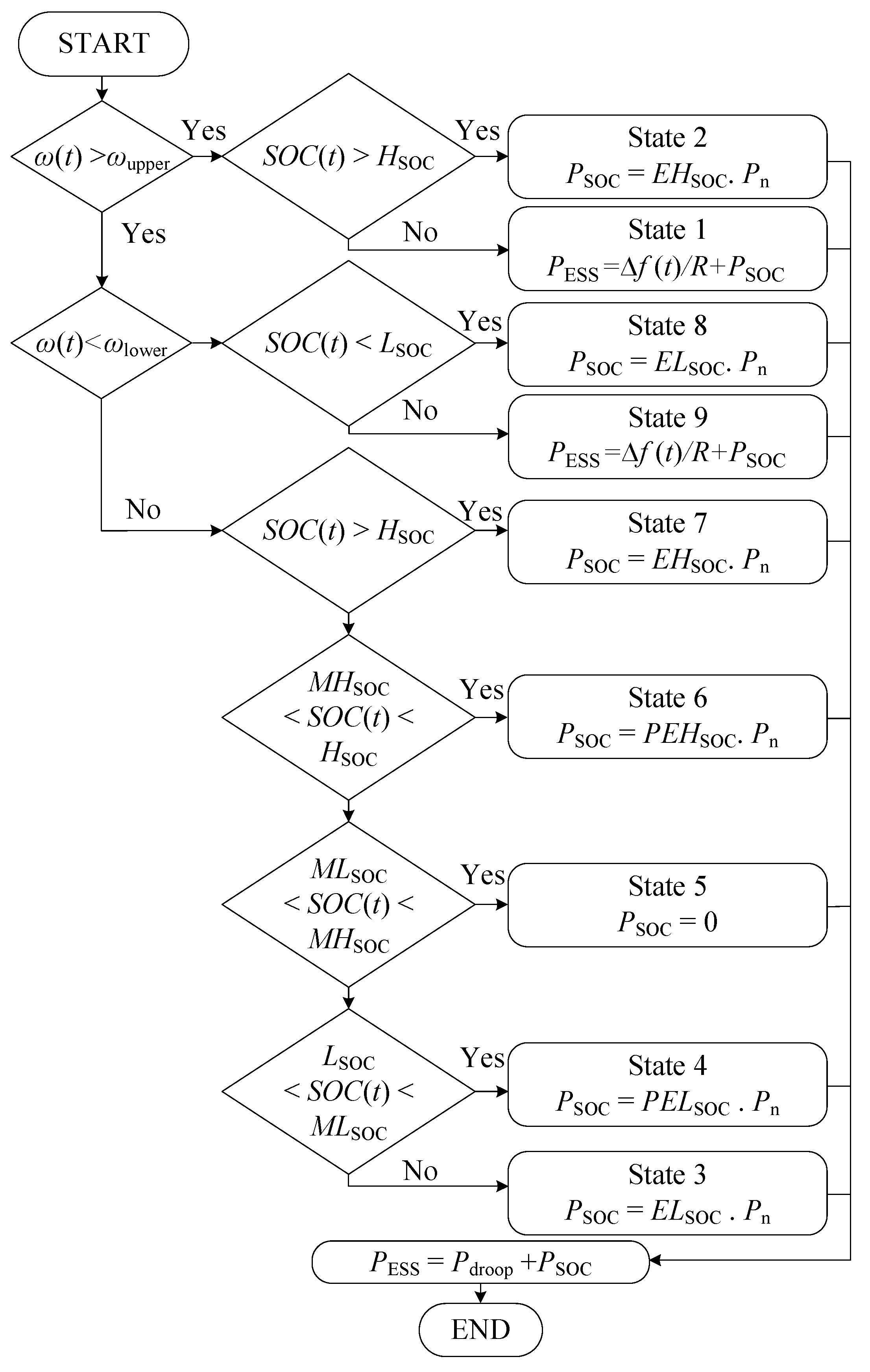
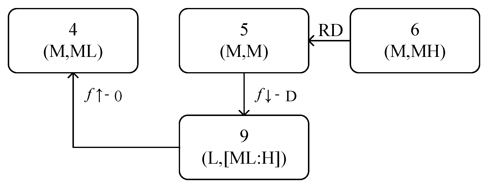
The condition changes of SOC and frequency in every moment result in state transition and ESS output power change for FR and SOC management. This state transition can be expressed with state machine as in Figure 6. The advantage of the state machine is to indicates which factor affects the movement of the state to another state. In this research, state is named as State 1 to 9, and in bracket below the numbers, the first letter indicates the high-, medium-, or low-frequency, and the letter behind indicates the level of SOC. The state movement, such as moving from State 1 to 2, from State 3 to 4, or State 4 to 5, results from the SOC increase, as indicated with the arrow. Likewise, in SOC decrease case, the movement of state is from State 9 to 8, State 7 to 6, or State 6 to 5. The state change from State 3∼6 to State 1 indicates the case with the frequency increase. Similarly, in case the frequency drops and crosses from the dead-band, state changes from State 4∼7 to State 9 as arrows. The movement of state can be affected by a change of frequency and SOC factor, and we may recognize having an influence of certain factors (SOC and frequency) on state movement using state machine. On the basis of these conditions, we may illustrate a flow chart as shown in Figure 7 and in this research, we develop the C code based on the flow chart in Figure 7.
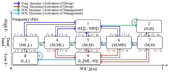
Figure 6.
State machine showing influential factors and state transition.

Figure 7.
Flow chart of implemented algorithm for frequency regulation and SOC management.
3.3.2. Example Case of Operation and State Transition
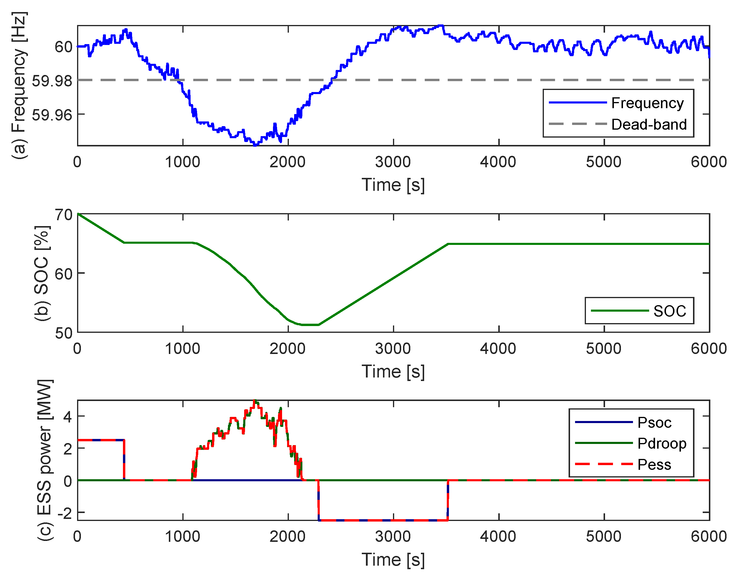
We intend to demonstrate the state changing process such as SOC management and frequency regulation in an example case according to the algorithm. As the frequency deviation occurs due to external disturbance, the generator angular speed also changes, and in case the rotation angular speed of generator exceeds the dead-band, the ESS reacts to frequency change to support frequency regulation instead of governor in conventional mechanism. Once the droop mode of ESS is activated, control algorithm retains the initial value and keeps this initial value until the droop mode is finished. This activation of droop mode remains certain set-up time as frequency sometimes fluctuates and this can be determined by ancillary service provision rule in ISO. In Figure 8, ESS power is determined according to two factors, frequency and SOC as in Figure 8a,b. Initially, since the frequency is located in the dead-band and the SOC is slightly higher, the discharge of ESS is performed to manage the SOC. Then, as the frequency deviation occurs and crosses the line of dead-band, the ESS release the power for frequency regulation as much as ((). In this regard, value added with value becomes ESS output power (). As ESS maintains supporting the grid, the SOC gradually continues to drop; however, the is not changed and remains constant value during droop mode in Figure 8c, as mentioned previously. After the deactivation of droop control, the value starts to change based on the SOC status. This scheme intends to fully support the generator without the power change for SOC management if frequency largely deviates. If the frequency comes back to the dead-band, the SOC management scheme activated using value so that the SOC reaches the desired Center Area. These series of changes can be analyzed with a state machine. By means of state machine, the change of the state can be analyzed and observed at a glance.
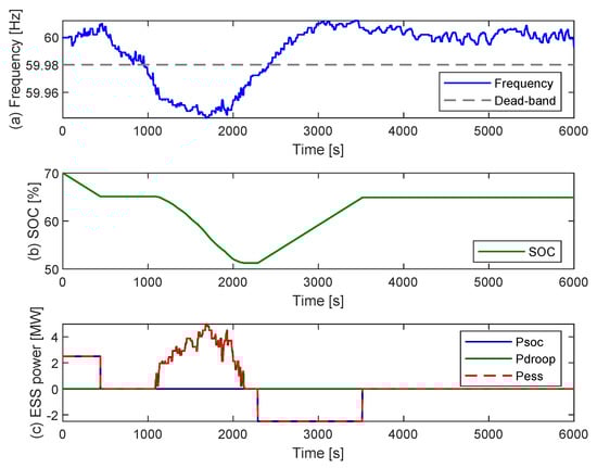
Figure 8.
Example case of operation by influential factors (Freq. and SOC) to ESS output power: (a) Grid frequency, (b) SOC, (c) ESS power.
As shown in Figure 9, the state is initially located in State 6, which is the state for discharging power and managing SOC. Secondly, as SOC management scheme well operates, the state moves to State 5, where the algorithm automatically intends to arrive. Then, as the frequency decreases due to external event, the state is relocated to State 9 for the frequency regulation from ESS to sustain generator angular speed. Lastly, the frequency returns into dead-band with moving to State 4, which also manages the SOC. Here, we can see what factors change the state through these series of processes with the state machine.

Figure 9.
State transition of example case in Figure 8.
3.3.3. Response of Governor and Governing ESS
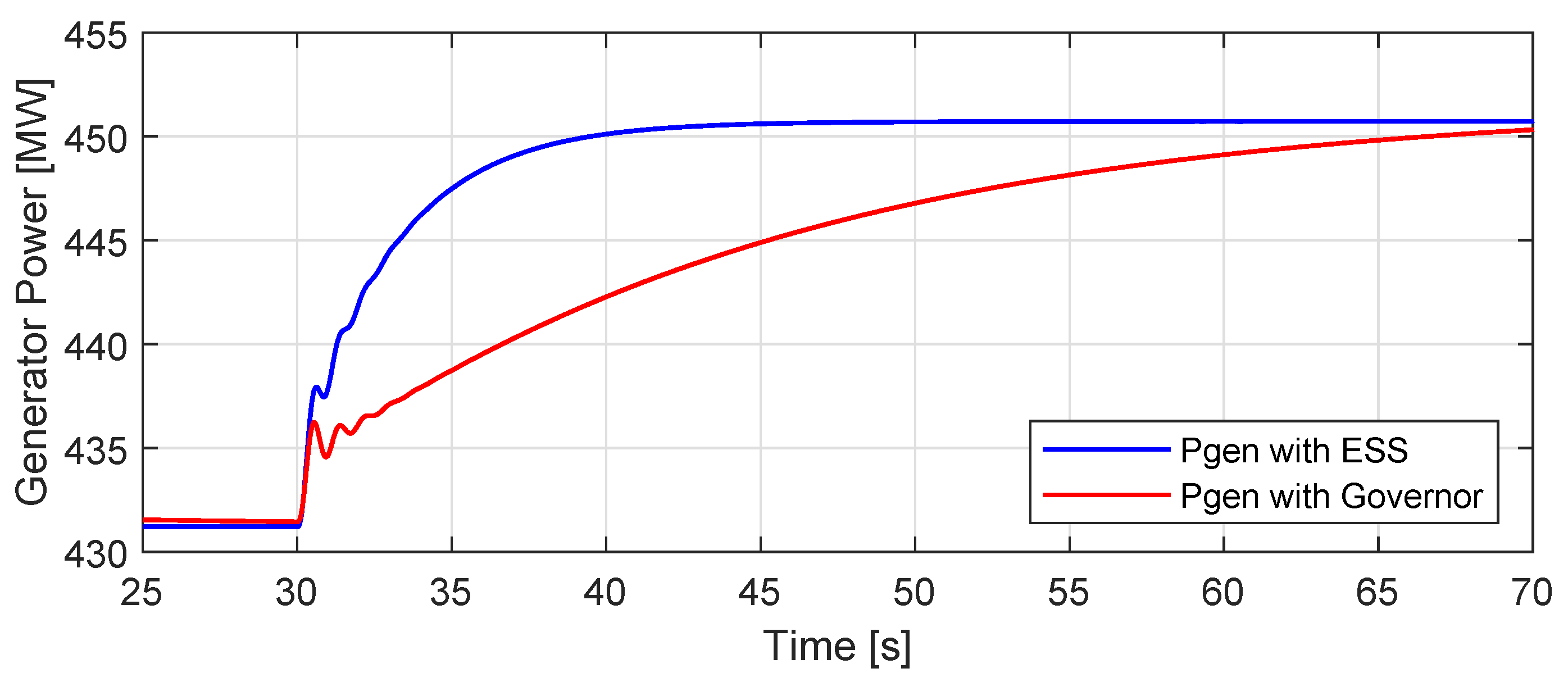
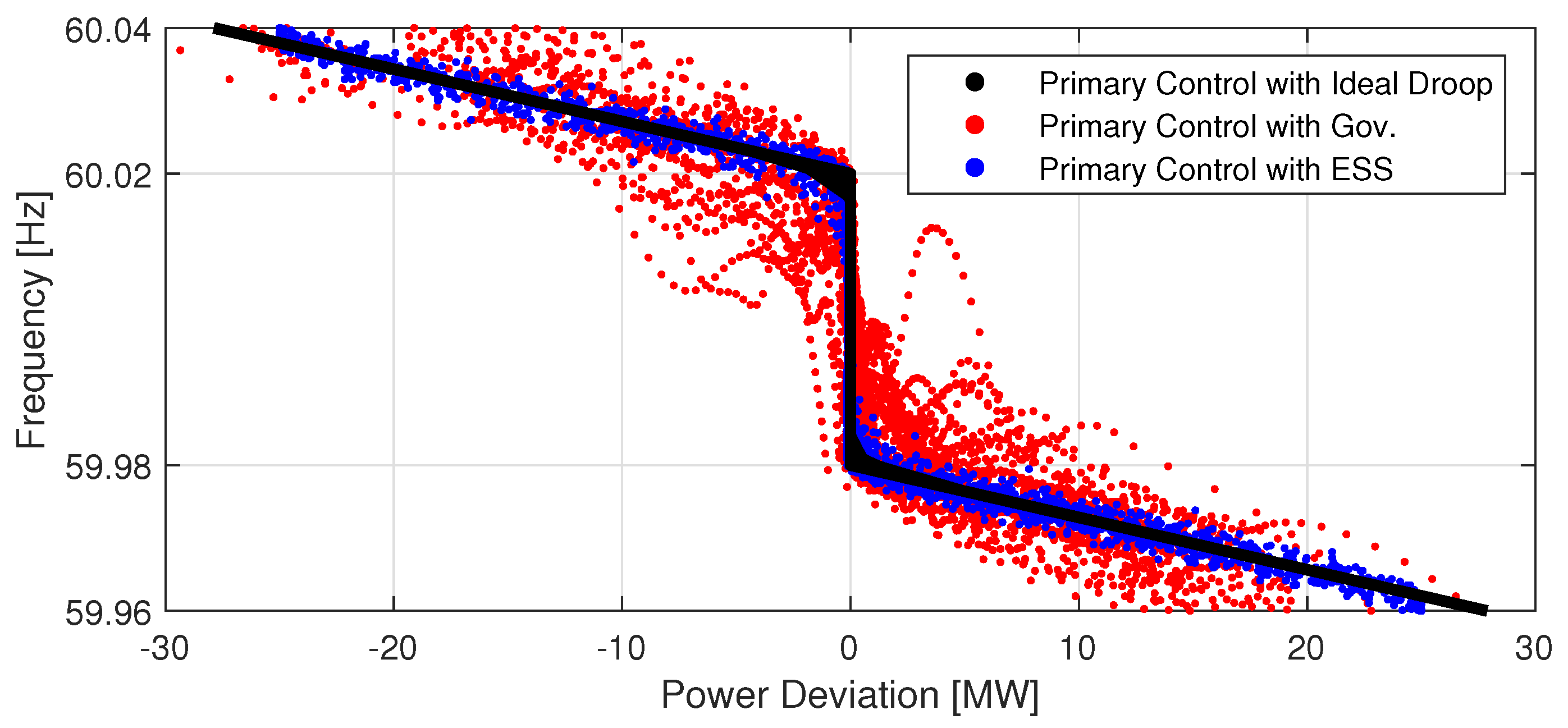
When a governor is installed for frequency regulation of the generator, the response has inherently slow characteristics due to the mechanical nature of inside of the governor. The speed response of generator with the governor is generally defined around several seconds, which has slower response than response of power electronic equipment. In the case of ESS, grid code in Korea requires the rise time of ESS should be within 200 ms, which is almost 5 to 10 times faster than the governor. In Figure 10, we indicate the case with the frequency step change to compare the two cases (the governor and ESS). As in Figure 10, the response of the generator with ESS is much more rapid than that of the generator with governor. This result implies that the supportive power can be provided to the power grid in a short time with highly enhanced dynamic characteristics from ESS, when the frequency deviation occurs. Figure 11 indicates the droop characteristics curve of between reference and measured value of ESS and governor case. This figure shows that the ESS drives almost consistently with the droop characteristic curve rather than in the case of the governor.
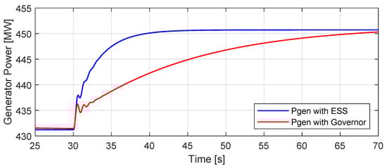
Figure 10.
Comparison of measured power response between Governor and ESS on generator against frequency step change.
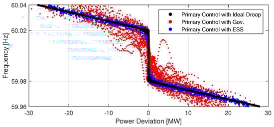
Figure 11.
Frequency-Power graph indicating distribution of droop control between conventional governor and proposed governing ESS.
4. Case Study
4.1. Network Condition and Configuration
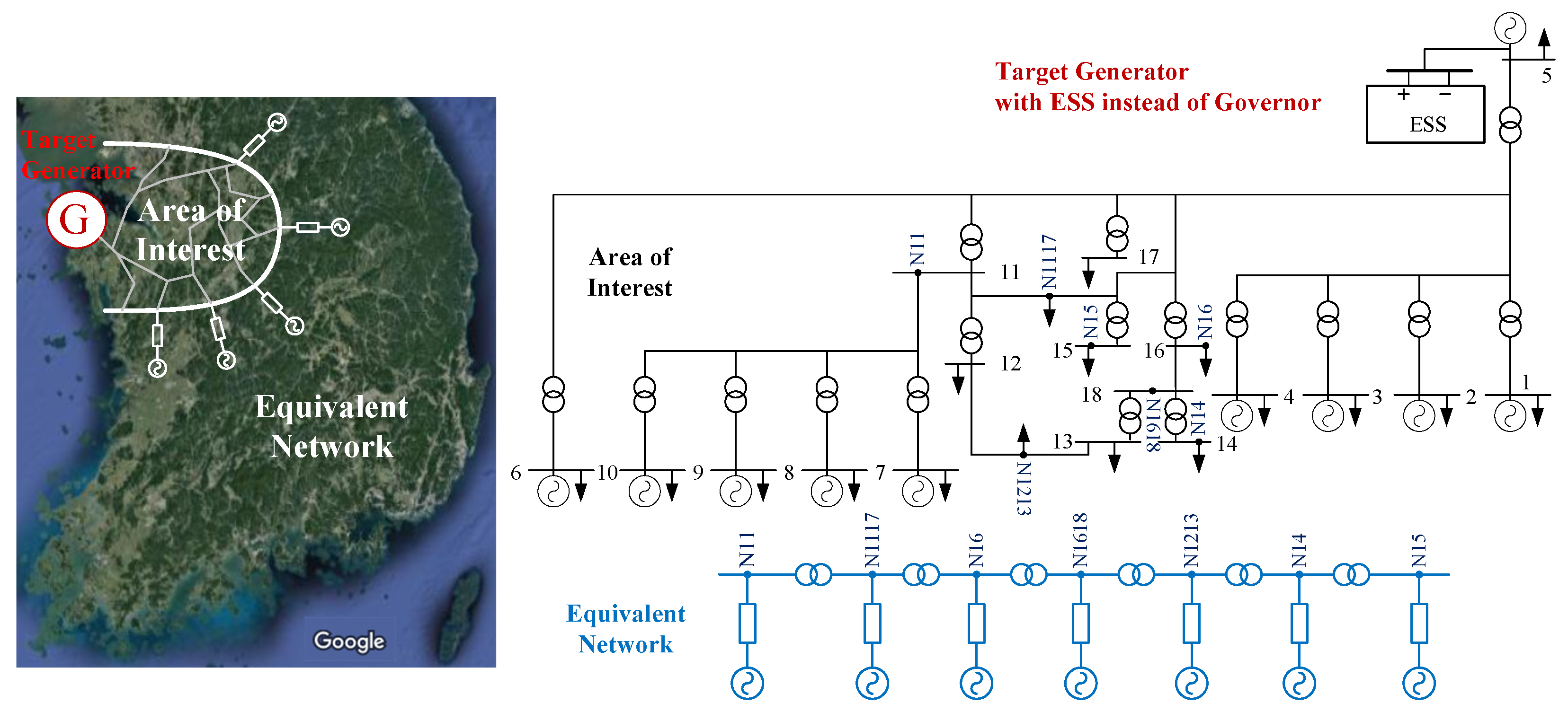
Figure 12 indicates the network in the northwest area in Korea, where 10 generators are located in area of interest, and other area is aggregated as equivalent network. The targeting generator on bus 5 is installed with ESS to improve the frequency stability. When the disturbance occurs in the network, ESS operates to reduce the impact on the generator.
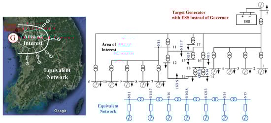
Figure 12.
Real Korean power network using model reduction method (source: Google Maps).
To verify the proposed study, case study was conducted using PSCAD/EMTDC, and we use network reduction model transformed from the data of PSS/e by ETRAN software. This system has the detailed network model in the area of interest, and the rest of the system transformed with equivalent system based on the real Korean network data. The ESS is installed on the target generator, with 612 MVA power rating and ESS rating is set as 25 MW converter rating and 6.25 MWh ESS capacity, as the specifications of the target generator and ESS at bus 5 are listed in Table 1. The effectiveness of ESS is verified with three case studies, organized in Table 2.

Table 1.
Parameters of Target Generator.
Table 2.
Case Study.
The results in Table 3 shows the compensation power of GEN-ESS is larger than the GEN-GOV in three cases. The frequency nadir can be defined as the largest deviation value from nominal frequency, which is from the instant mismatch between generation and demand. The Table 3 shows the generator with ESS has lower frequency nadir value which implies ESS faster action reduces the frequency deviation of generator. Furthermore, instant compensation power in case of generator with ESS shows higher value due to fast action, compared to that of generator with governor. The indicators regarding electrical torque from generator viewpoint reduces and leads less torque deviation, resulting in less frequency deviation.
Table 3.
Results from case studies.
4.2. Case 1: Generator Trip
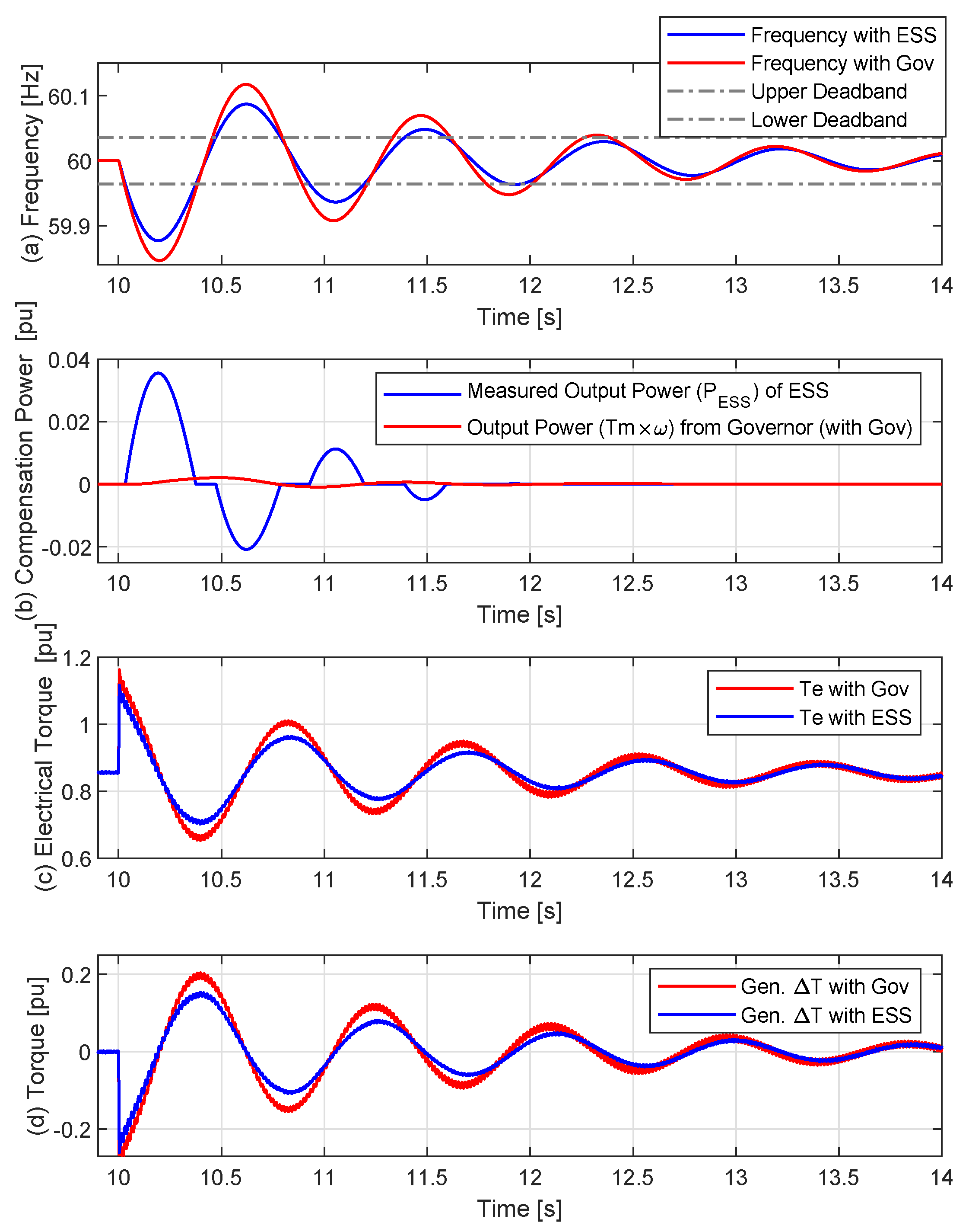
The first case indicates the generator trip, and in this study Generators 1, 2, 3, and 4 in the vicinity of the target generator are tripped simultaneously. In case the group of generators in the power system are tripped, the mismatch of the power balance significantly affects nearby generators, causing large frequency deviation. In this case study, the ESS instead of governor takes responsibility of power compensation and brings an advantage of rapid compensation, as ESS has timely appropriate compensation ability. Figure 13 indicates the frequency changes after the generator trip as shown in Figure 13a. To compensate power for this oscillating frequency, the compensation power from ESS is provided to the power system as in Figure 13b. As the oscillation is comparatively faster than governor, the governor cannot properly compensate the power; however, as ESS has an ability to provide rapidly compensation power, compensation power rapidly increases instantaneously which stabilizes the system. Due to the ESS power provision, electrical power reduces from the generator perspectives as shown in Figure 13c, resulting in the decrease of difference between the mechanical torque and the electrical torque (the generator torque deviation ) as in Figure 13d. As the generator torque deviation has the less change in case of the ESS installation instead of governor, frequency eventually reduces as in Figure 13a.
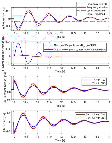
Figure 13.
Generator trip case; (a) generator frequency, (b) output power of ESS and Governor, (c) electrical torque of generator, (d) torque deviation () of generator.
4.3. Case 2: Temporary Fault
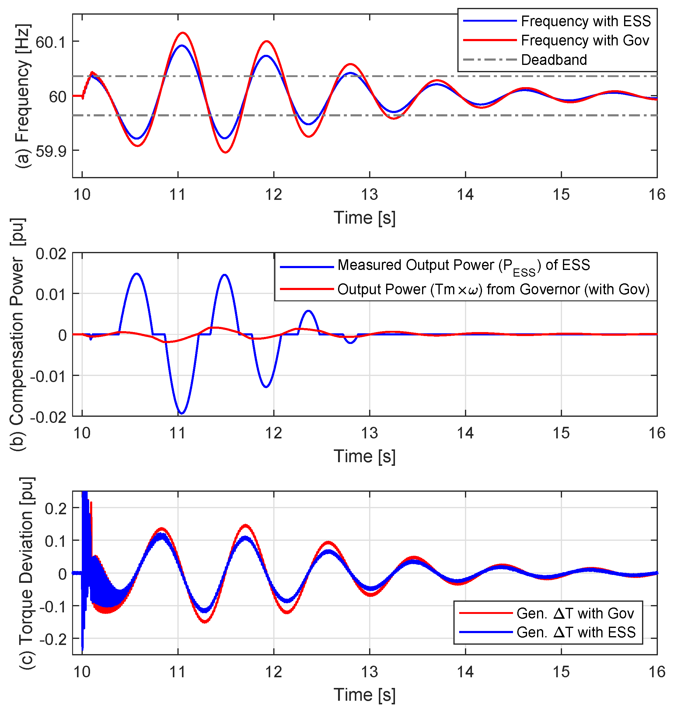
In Case 2, a temporary fault was applied on bus 11 of the three-phase fault, and then cleared after 5 cycles. Figure 14 shows that frequency deviation occurs during the fault, and frequency oscillates even after the fault clearing. In case of torque deviation, As the event of a fault occurs highly short time, the governor hardly responds to the large frequency deviation. On the other hand, ESS has highly fast the response characteristic against frequency deviation in Figure 14b resulting in torque deviation in the synchronous generator as in Figure 14c, so that it can provide the power to reduce generator rotating speed deviation in Figure 14a.
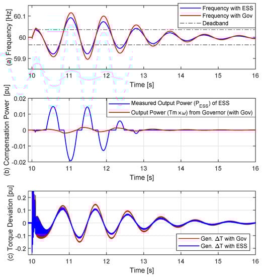
Figure 14.
Temporary fault case; (a) generator frequency, (b) output power of ESS and Governor, (c) electrical torque of Generator.
4.4. Case 3: Permanent Fault
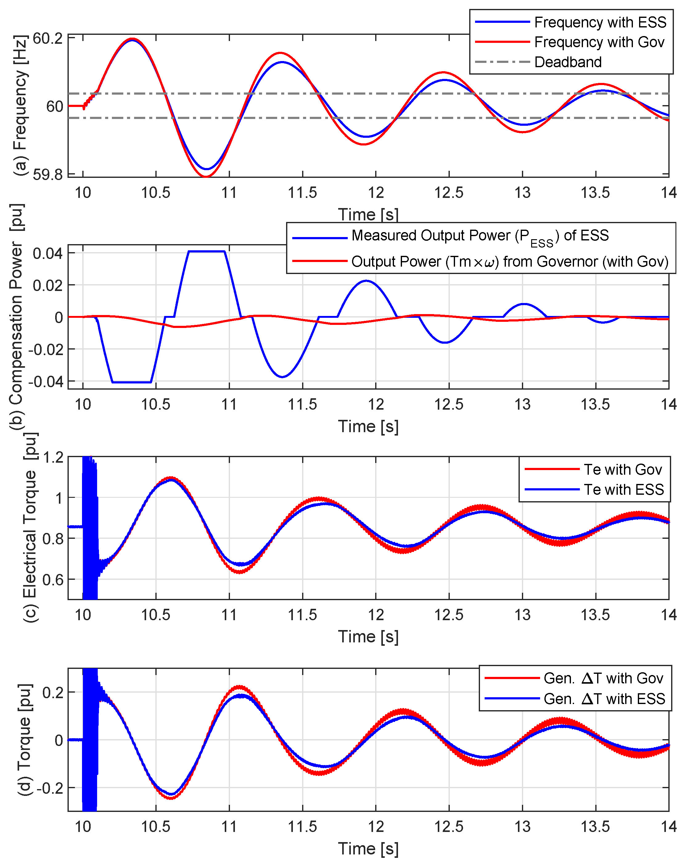
The last case study is the permanent fault case, and the line is blocked instantly. In this case, the power does not smoothly flow from generators to the load side, so that the frequency instantly increases. Thus, the ESS rapidly controls the generator frequency to be operated in a stable manner. As shown in Figure 15, ESS tries to provide the power as much as it can in response to frequency fluctuation in Figure 15b, so that electrical power inside of the synchronous generator decreases in case of ESS installation instead of governor. This leads to a decrease of deviation due to the rapid response of the ESS. Consequently, this governing ESS reduces the frequency fluctuation as can be seen in Figure 15a.
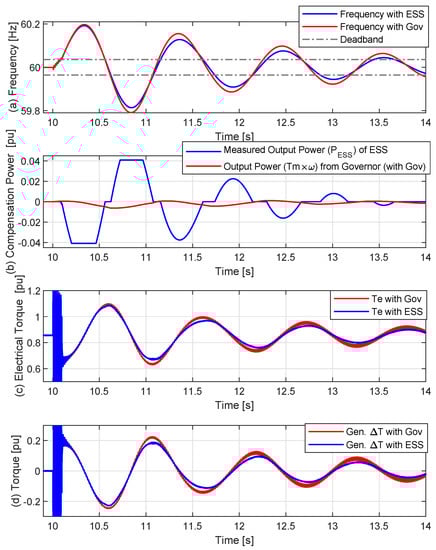
Figure 15.
Permanent fault case with line trip; (a) generator frequency, (b) output power of ESS and Governor, (c) electrical torque of Generator, (d) torque deviation () of Generator.
5. Conclusions
In this paper, we introduced operation scheme of ESS interfacing with generator and several advantages in case of frequency regulation from generator operated by ESS instead of governor in dynamic characteristics perspectives. We first shed light on the SOC management of ESS, which is expressed in the form of state-flow and the algorithm implementation with example. Then, we deliver the advantages of governing ESS on Generator through several case studies. We also show several case studies such as generator trip, line fault, and breaker operation case. Among these case studies, we observed ESS application on generator exhibits better performance than conventional governor control. Installation of ESS instead of a turbine governor on generator can be considered as generator can operate without a reserve, which potentially reduces operating costs. As ascertained from the research above, the ESS interfacing with generator can effectively reduce the angular speed deviation of conventional generator.
Author Contributions
Conceptualization, J.Y.; methodology, J.W.S.; validation, C.L.; formal analysis, N.-D.N.-H., W.S., C.L., J.Y., J.M. and M.Y.; investigation, N.-D.N.-H. and W.S.; writing—original draft preparation, N.-D.N.-H.; writing—review and editing, M.Y., K.H. and J.W.S.; visualization, N.-D.N.-H. and W.S.; supervision, J.W.S.; project administration, I.-Y.C., D.K., Y.-H.H.; funding acquisition, I.-Y.C. All authors have read and agreed to the published version of the manuscript.
Funding
This research is funded by a 2021 research Grant from Sangmyung University (Grant Number: 2021-A000-0086).
Conflicts of Interest
The authors declare no conflict of interest.
References
- KERMIT. To Determine the Effectiveness of the AGC in Controlling Fast and Conventional Resources in the PJM Frequency Regulation Market; KERMIT Study Report; Technical Report Statement of Work 11-3099; KEMA Inc.: Chalfont, PA, USA, 2011. [Google Scholar]
- Allen, D.; Brown, C.; Hickey, J.; Le, V.; Safuto, R. Energy Storage in the New York Electricity Market; Technical Report; New York Independent System Operator (NYISO): Rensselaer, NY, USA, 2010. [Google Scholar]
- ERCOT. Future Ancillary Services in ERCOT; Technical Report; Electric Reliability Council of Texas (ERCOT): Austin, TX, USA, 2013. [Google Scholar]
- Hur, W.; Moon, Y.; Shin, K.; Kim, W.; Nam, S.; Park, K. Economic Value of Li-ion Energy Storage System in Frequency Regulation Application from Utility Firm’s Perspective in Korea. Energies 2015, 8, 5000–5017. [Google Scholar] [CrossRef]
- Van der Hoeven, M. Technology Roadmap: Energy Storage; Technical Report; International Energy Agency (IEA): Paris, France, 2014. [Google Scholar]
- Atanacio, M.; Fioravanti, R.; Katzenstein, W.; Vu, K. Emission II Study of Advanced Storage Used for Frequency Regulation; Technical Report Sandia Negotiation 96362; Sandia National Laboratories: Albuquerque, NM, USA, 2011. [Google Scholar]
- Shim, J.W.; Verbič, G.; Kim, H.; Hur, K. On Droop Control of Energy-Constrained Battery Energy Storage Systems for Grid Frequency Regulation. IEEE Access 2019, 7, 166353–166364. [Google Scholar] [CrossRef]
- Bose, U.; Chattopadhyay, S.K.; Chakraborty, C.; Pal, B. A Novel Method of Frequency Regulation in Microgrid. IEEE Trans. Ind. Appl. 2019, 55, 111–121. [Google Scholar] [CrossRef]
- Guo, F.; Sharma, R. Hybrid Energy Storage Systems integrating battery and Ultracapacitor for the PJM frequency regulation market. In Proceedings of the 2016 IEEE Power and Energy Society General Meeting (PESGM), Boston, MA, USA, 17–21 July 2016; pp. 1–4. [Google Scholar]
- Padmanabhan, N.; Ahmed, M.; Bhattacharya, K. Battery Energy Storage Systems in Energy and Reserve Markets. IEEE Trans. Power Syst. 2020, 35, 215–226. [Google Scholar] [CrossRef]
- Wu, D.; Tang, F.; Dragicevic, T.; Guerrero, J.M.; Vasquez, J.C. Coordinated Control Based on Bus-Signaling and Virtual Inertia for Islanded DC Microgrids. IEEE Trans. Smart Grid 2015, 6, 2627–2638. [Google Scholar] [CrossRef] [Green Version]
- Wu, D.; Tang, F.; Dragicevic, T.; Vasquez, J.C.; Guerrero, J.M. Autonomous Active Power Control for Islanded AC Microgrids with Photovoltaic Generation and Energy Storage System. IEEE Trans. Energy Convers. 2014, 29, 882–892. [Google Scholar] [CrossRef] [Green Version]
- Simpson-Porco, J.W.; Shafiee, Q.; Dörfler, F.; Vasquez, J.C.; Guerrero, J.M.; Bullo, F. Secondary Frequency and Voltage Control of Islanded Microgrids via Distributed Averaging. IEEE Trans. Ind. Electron. 2015, 62, 7025–7038. [Google Scholar] [CrossRef]
- Shim, J.W.; Verbič, G.; Zhang, N.; Hur, K. Harmonious Integration of Faster-Acting Energy Storage Systems Into Frequency Control Reserves in Power Grid with High Renewable Generation. IEEE Trans. Power Syst. 2018, 33, 6193–6205. [Google Scholar] [CrossRef]
- Tan, J.; Zhang, Y. Coordinated Control Strategy of a Battery Energy Storage System to Support a Wind Power Plant Providing Multi-Timescale Frequency Ancillary Services. IEEE Trans. Sustain. Energy 2017, 8, 1140–1153. [Google Scholar] [CrossRef]
- Nguyen, V.T.; Shim, J.W. Virtual Capacity of Hybrid Energy Storage Systems Using Adaptive State of Charge Range Control for Smoothing Renewable Intermittency. IEEE Access 2020, 8, 126951–126964. [Google Scholar] [CrossRef]
- Shim, J.; Kim, H.; Hur, K. Incorporating State-of-Charge Balancing into the Control of Energy Storage Systems for Smoothing Renewable Intermittency. Energies 2019, 12, 1190. [Google Scholar] [CrossRef] [Green Version]
- Shim, J.W. The Impact of Large-Scale Renewable Energy on Grid Small-Signal and Frequency Stability: Modelling, Analysis, and Control. Ph.D. Thesis, The University of Sydney, Sydney, Australia, 2016. [Google Scholar]
- Chung, I.Y.; Liu, W.; Cartes, D.A.; Collins, E.G.; Moon, S.I. Control Methods of Inverter-Interfaced Distributed Generators in a Microgrid System. IEEE Trans. Ind. Appl. 2010, 46, 1078–1088. [Google Scholar] [CrossRef]
- Dang, J.; Seuss, J.; Suneja, L.; Harley, R.G. SOC feedback control for wind and ESS hybrid power system frequency regulation. In Proceedings of the IEEE Power Electronics and Machines in Wind Applications (PEMWA) 2012, Denver, CO, USA, 16–18 July 2012; pp. 1–7. [Google Scholar] [CrossRef]
- Liu, H.; Hu, Z.; Song, Y.; Lin, J. Decentralized Vehicle-to-Grid Control for Primary Frequency Regulation Considering Charging Demands. IEEE Trans. Power Syst. 2013, 28, 3480–3489. [Google Scholar] [CrossRef]
- Ota, Y.; Taniguchi, H.; Nakajima, T.; Liyanage, K.M.; Baba, J.; Yokoyama, A. Autonomous Distributed V2G (Vehicle-to-Grid) Satisfying Scheduled Charging. IEEE Trans. Smart Grid 2012, 3, 559–564. [Google Scholar] [CrossRef]
- Zeng, J.; Zhang, B.; Mao, C.; Wang, Y. Use of Battery Energy Storage System to Improve the Power Quality and Stability of Wind Farms. In Proceedings of the 2006 International Conference on Power System Technology, Chongqing, China, 22–26 October 2006; pp. 1–6. [Google Scholar]
- Jiang, Q.; Gong, Y.; Wang, H. A Battery Energy Storage System Dual-Layer Control Strategy for Mitigating Wind Farm Fluctuations. IEEE Trans. Power Syst. 2013, 28, 3263–3273. [Google Scholar] [CrossRef]
- Uchida, Y.; Koshimizu, G.; Nanahara, T.; Yoshimoto, K.; Uchida, Y.; Koshimizu, G.; Nanahara, T.; Yoshimoto, K. New Control Method for Regulating State-of- Charge of a Battery in Hybrid Wind Power/Battery Energy Storage System. In Proceedings of the 2006 IEEE PES Power Systems Conference and Exposition, Atlanta, GA, USA, 29 October–1 November 2006; pp. 1244–1251. [Google Scholar]
- Hill, C.; Such, M.; Chen, D.; Gonzalez, J.; Grady, W. Battery Energy Storage for Enabling Integration of Distributed Solar Power Generation. IEEE Trans. Smart Grid 2012, 3, 850–857. [Google Scholar] [CrossRef]
- Nguyen-Huu, T.A.; Nguyen, V.T.; Hur, K.; Shim, J.W. Coordinated Control of a Hybrid Energy Storage System for Improving the Capability of Frequency Regulation and State-of-Charge Management. Energies 2020, 13, 6304. [Google Scholar] [CrossRef]
- Kreeumporn, W.; Ngamroo, I. Integrated superconducting coil into PV generator for power smoothing and voltage regulation. In Proceedings of the 2015 IEEE International Conference on Applied Superconductivity and Electromagnetic Devices (ASEMD), Shanghai, China, 20–23 November 2015; pp. 159–160. [Google Scholar] [CrossRef]
- IEEE Committee. Dynamic models for steam and hydro turbines in power system studies. IEEE Trans. Power Appar. Syst. 1973, PAS-92, 1904–1915. [Google Scholar] [CrossRef]
- Zhou, T.; Zhang, T.; Liu, L.; Gu, W.; Guo, M.; Zheng, J. AGC Frequency Regulation Performance Evaluation Index Considering Disturbed Operating Conditions. In Proceedings of the 2020 12th IEEE PES Asia-Pacific Power and Energy Engineering Conference (APPEEC), Nanjing, China, 20–23 September 2020; pp. 1–5. [Google Scholar] [CrossRef]
- Karaki, A.; Shadmand, M.B.; Abu-Rub, H.; Bayhan, S. Virtual Inertia Emulation Inspired Predictive Control to Improve Frequency Stability in Power Electronics Dominated Grid. In Proceedings of the 2021 IEEE 12th International Symposium on Power Electronics for Distributed Generation Systems (PEDG), Chicago, IL, USA, 28 June–1 July 2021; pp. 1–6. [Google Scholar] [CrossRef]
- Cho, S.M.; Yun, S.Y. Optimal Power Assignment of Energy Storage Systems to Improve the Energy Storage Efficiency for Frequency Regulation. Energies 2017, 10, 2092. [Google Scholar] [CrossRef] [Green Version]
- Yun, J.Y.; Yu, G.; Kook, K.S.; Rho, D.H.; Chang, B.H. SOC-based Control Strategy of Battery Energy Storage System for Power System Frequency Regulation. Trans. Korean Inst. Electr. Eng. 2014, 63, 622–628. [Google Scholar] [CrossRef] [Green Version]
- Lim, G.-P.; Park, C.-W.; Labios, R.; Yoon, Y.-B. Development of Control Algorithm of ESS for Frequency Regulation in Power System. KEPCO J. Electr. Power Energy 2015, 1, 9–13. [Google Scholar] [CrossRef] [Green Version]
- Kundur, P. Power System Stability and Control (The EPRI Power System Engineering Series); McGraw-Hill: New York, NY, USA, 1994. [Google Scholar]
- Tremblay, O.; Dessaint, L.A. Experimental Validation of a Battery Dynamic Model for EV Applications. World Electr. Veh. J. 2009, 3, 289–298. [Google Scholar] [CrossRef] [Green Version]
- Shepherd, C.M. Design of Primary and Secondary Cells. J. Electrochem. Soc. 1965, 112, 657. [Google Scholar] [CrossRef]
- Hannan, M.A.; Hoque, M.M.; Hussain, A.; Yusof, Y.; Ker, P.J. State-of-the-Art and Energy Management System of Lithium-Ion Batteries in Electric Vehicle Applications: Issues and Recommendations. IEEE Access 2018, 6, 19362–19378. [Google Scholar] [CrossRef]
- Roscher, M.A.; Bohlen, O.S.; Sauer, D.U. Reliable State Estimation of Multicell Lithium-Ion Battery Systems. IEEE Trans. Energy Convers. 2011, 26, 737–743. [Google Scholar] [CrossRef]
- Mamun, A.; Liu, Z.; Rizzo, D.M.; Onori, S. An Integrated Design and Control Optimization Framework for Hybrid Military Vehicle Using Lithium-Ion Battery and Supercapacitor as Energy Storage Devices. IEEE Trans. Transp. Electrif. 2019, 5, 239–251. [Google Scholar] [CrossRef]


Publisher’s Note: MDPI stays neutral with regard to jurisdictional claims in published maps and institutional affiliations. |
© 2022 by the authors. Licensee MDPI, Basel, Switzerland. This article is an open access article distributed under the terms and conditions of the Creative Commons Attribution (CC BY) license (https://creativecommons.org/licenses/by/4.0/).