
Optimization of a Membraneless Microfluidic Fuel Cell with a Double-Bridge Flow Channel


Abstract
:1. Introduction
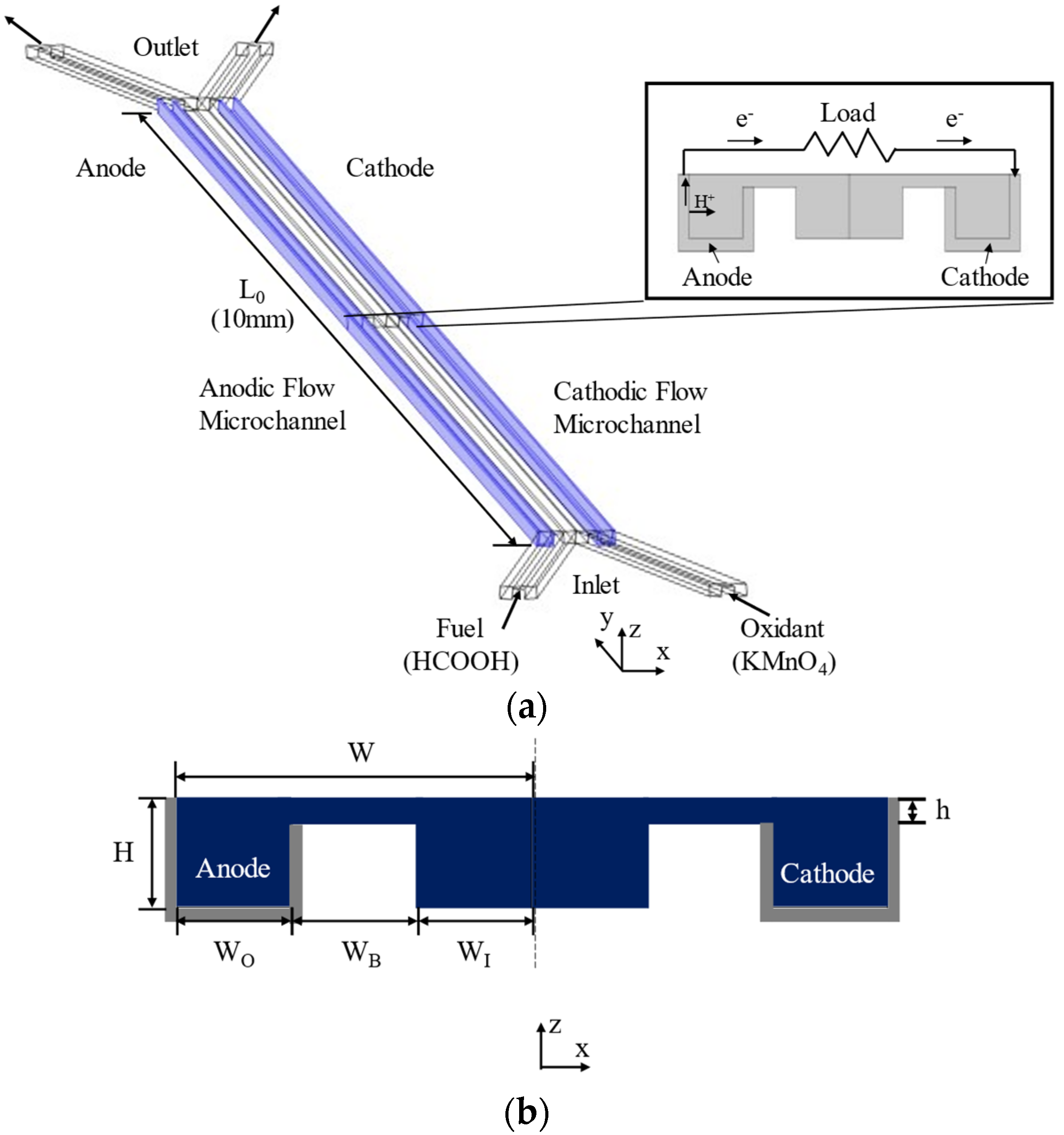
2. MMFC Geometry
3. Numerical Analysis
4. Optimization Technique
4.1. Design Variables
4.2. Optimization Methodology
4.2.1. Design of Experiment
4.2.2. Radial Basis Neural Network
4.2.3. Searching Algorithms
5. Results and Discussion
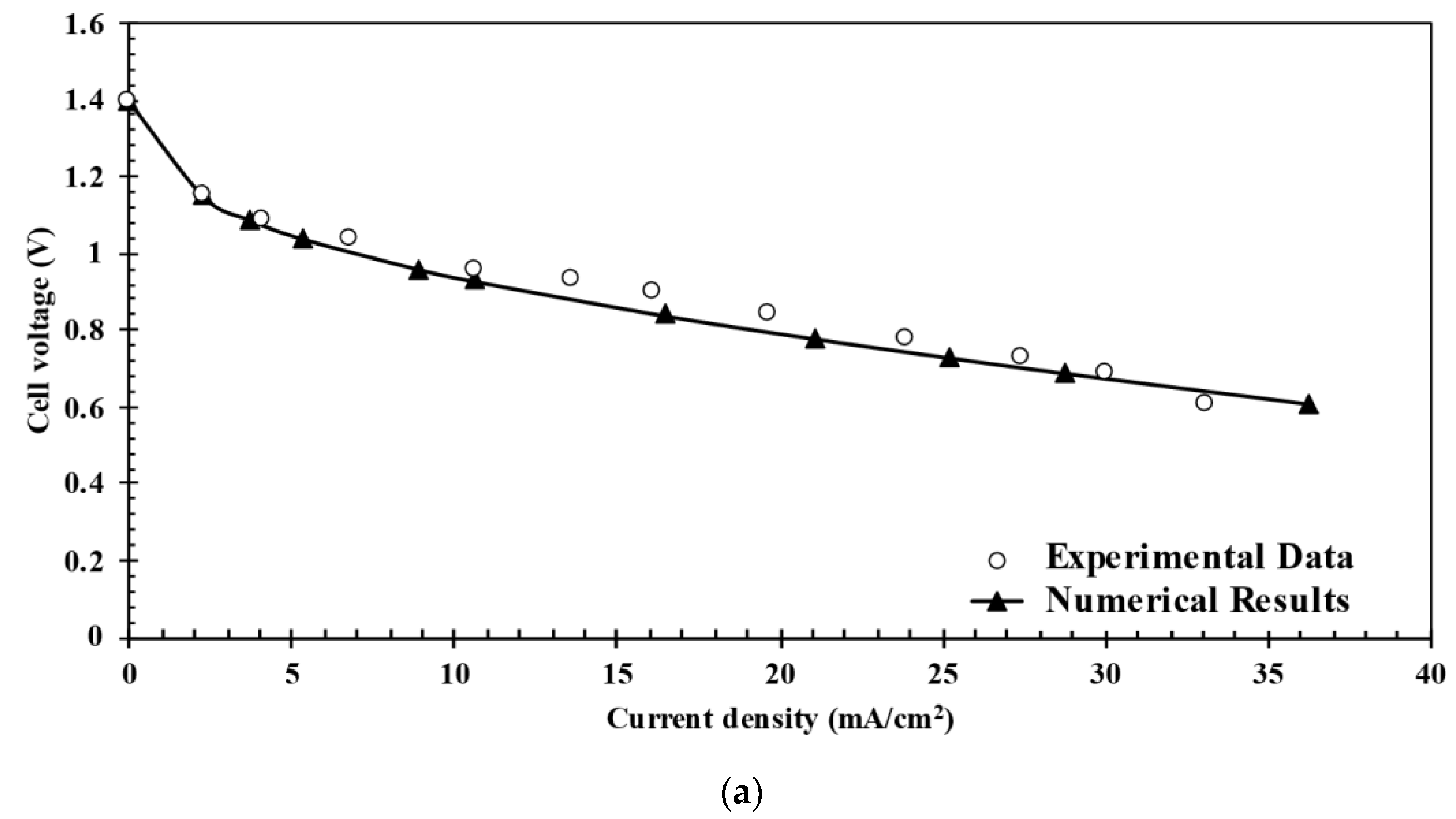
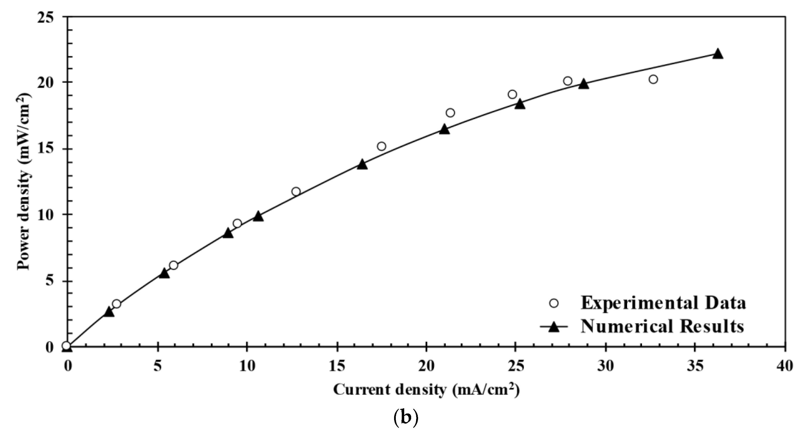
5.1. Grid Convergence Index Analysis and Validation of Numerical Results
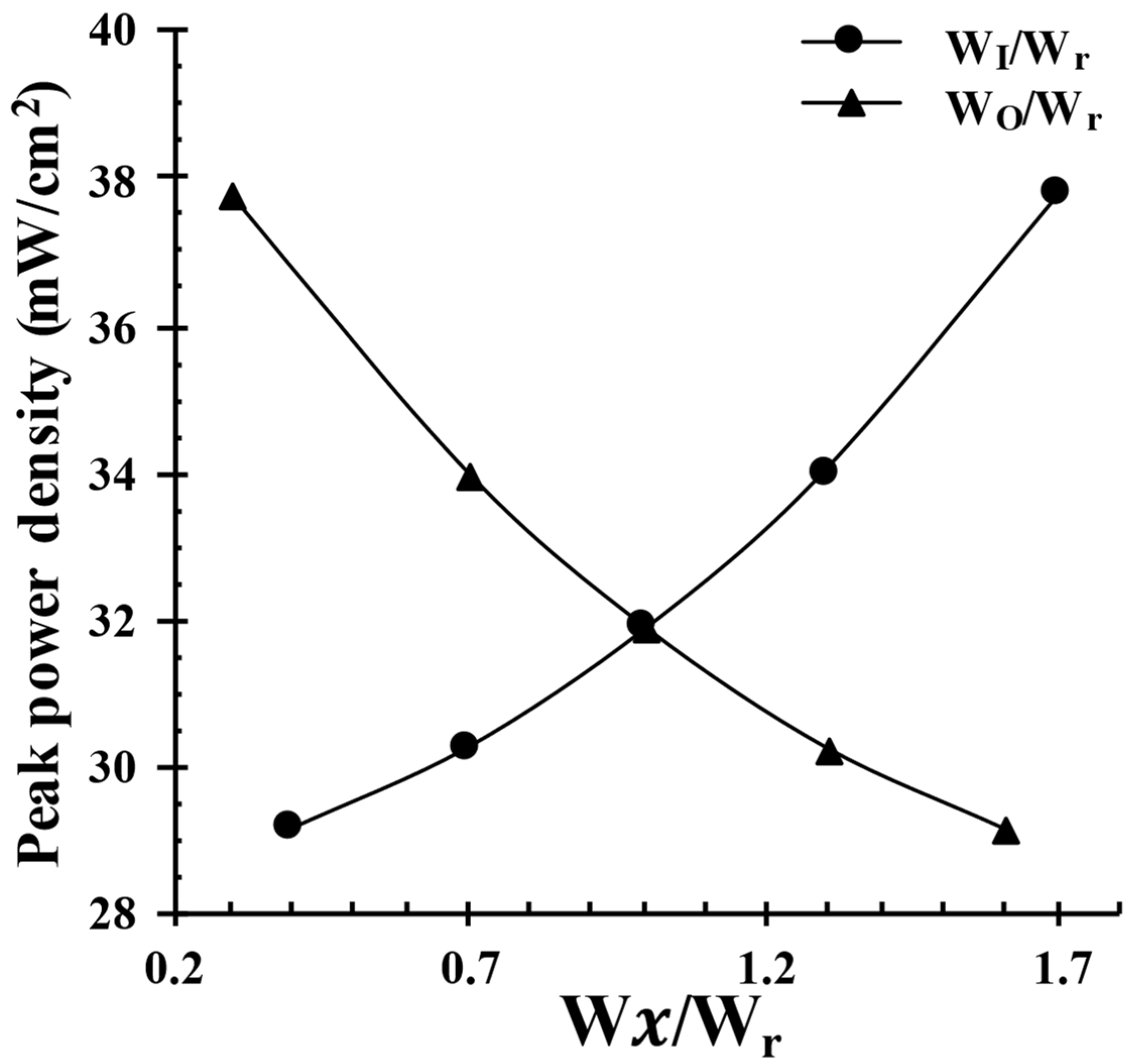
5.2. Optimization Results
6. Conclusions
Author Contributions
Funding
Institutional Review Board Statement
Informed Consent Statement
Data Availability Statement
Conflicts of Interest
References
- Omar, Z.; Sharaf; Mehmet, F.; Orhan. An overview of fuel cell technology: Fundamentals and applications. Renew. Sustain. Energy Rev. 2014, 32, 810–853. [Google Scholar]
- Kamarudin, S.K.; Daud, W.R.W.; Som, A.M.; Takriff, M.S.; Mohammad, A.W.; Loke, Y.K. Design of a fuel processor unit for PEM fuel cell via shortcut design method. Chem. Eng. J. 2004, 104, 7–17. [Google Scholar] [CrossRef]
- Tabbi, W.; Alaswad, A.; Palumbo, A.; Dassisti, M.; Olabi, A.G. Advances in stationary and portable fuel cell applications. Int. J. Hydrogen Energy 2016, 41, 16509–16522. [Google Scholar]
- Motokawa, S.; Mohamedi, M.; Momma, T.; Shoji, S.; Osaka, T. MEMS-based design and fabrication of a new concept micro direct methanol fuel cell (l-DMFC). Electrochem. Commun. 2004, 6, 562–565. [Google Scholar] [CrossRef]
- Goor, M.; Menkin, S.; Peled, E. High power direct methanol fuel cell for mobility and portable applications. Int. J. Hydrogen Energy 2019, 44, 3138–3143. [Google Scholar] [CrossRef]
- Pan, Z.F.; Chen, R.; An, L.; Li, Y.S. Alkaline anion exchange membrane fuel cells for cogeneration of electricity and valuable chemicals. J. Power Sources 2017, 365, 430–445. [Google Scholar] [CrossRef]
- Adhami, H. Designing and analysis of the micro-trigeneration systems based on combined proton exchange membrane fuel cell with photovoltaic and photovoltaic/thermal prime movers in portable applications. Appl. Therm. Eng. 2020, 180, 115779. [Google Scholar] [CrossRef]
- Xiao, Z.Y.; Feng, C.H.; Chan, P.C.H.; Hsing, I.M. Monolithically integrated planar microfuel cell arrays. Sens. Actuators B 2008, 132, 576–586. [Google Scholar] [CrossRef]
- Alias, M.S. Active direct methanol fuel cell: An overview. Int. J. Hydrogen Energy 2020, 45, 19620–19641. [Google Scholar] [CrossRef]
- Singh, R. Bio-compatible bio-fuel cells for medical devices. Mater. Today Proc. 2021, 44, 242–249. [Google Scholar] [CrossRef]
- Patil, A.; Dubois, T.G.; Sifer, N.; Bostic, E.; Gardner, K.; Quah, M.; Bolton, C. Portable fuel cell systems for America’s army: Technology transition to the field. J. Power Sources 2004, 136, 220–225. [Google Scholar] [CrossRef]
- Dyer, C.K. Fuel cells for portable applications. J. Power Sources 2002, 106, 31–34. [Google Scholar] [CrossRef]
- Lee, S.J.; Chang-Chien, A.; Cha, S.W.; O’Hayre, R.; Park, Y.I.; Saito, Y.; Prinz, F.B. Design and fabrication of a micro fuel cell array with “flip-flop” interconnection. J. Power Sources 2002, 112, 410–418. [Google Scholar] [CrossRef]
- Choban, E.R.; Markoski, L.J.; Wieckowski, A.; Kenis, P.J.A. Microfluidic fuel cell based on laminar flow. J. Power Sources 2004, 128, 54–60. [Google Scholar] [CrossRef]
- Ferrigno, R.; Stroock, A.D.; Clark, T.D.; Mayer, M.; Whitesides, G.M. Membraneless Vanadium Redox Fuel Cell Using Laminar Flow. J. Am. Chem. Soc. 2002, 124, 12930–12931. [Google Scholar] [CrossRef]
- Choban, E.R.; Spendelow, J.S.; Gancs, L.; Wieckowski, A.; Kenis, P.J.A. Membraneless laminar flow-based micro fuel cells operating in alkaline, acidic, and acidic/alkaline media. Electrochim. Acta 2005, 50, 5390–5398. [Google Scholar] [CrossRef]
- López-Montesinos, P.O.; Yossakda, N.; Schmidt, A.; Brushett, F.R.; Pelton, W.E.; Kenis, P.J.A. Design, fabrication, and characterization of a planar, silicon-based, monolithically integrated micro laminar flow fuel cell with a bridge-shaped microchannel cross-section. J. Power Sources 2001, 196, 4638–4645. [Google Scholar] [CrossRef]
- Hanapi, I.H.; Kaarudin, S.K.; Zainoodin, A.M.; Hasran, U.A. Memrane-less micro fuel cell system design and performance: An overview. Int. J. Energy Res. 2019, 43, 8956–8972. [Google Scholar] [CrossRef]
- Tanveer, M.; Kim, K.Y. Effects of geometric configuration of the channel and electrodes on the performance of a membraneless micro-fuel cell. Energy Convers. Manag. 2017, 136, 372–381. [Google Scholar] [CrossRef]
- Hollinger, A.S.; Maloney, R.J.; Jayashree, R.S.; Natarajan, D.; Markoski, L.J.; Kenis, P.J.A. Nanoporous separator and low fuel concentration to minimize crossover in direct methanol laminar flow fuel cells. J. Power Sources 2010, 195, 3523–3528. [Google Scholar] [CrossRef]
- Sun, M.H.; Velve Casquillas, G.; Guo, S.S.; Shi, J.; Ji, H.; Ouyang, Q.; Chen, Y. Characterization of microfluidic fuel cell based on multiple laminar flow. Microelectron. Eng. 2007, 84, 1182–1185. [Google Scholar] [CrossRef]
- Jayashree, R.S.; Yoon, S.K.; Brushett, F.R.; Lopez-Montesinos, P.O.; Natarajan, D.; Markoski, L.J.; Kenis, P.J.A. On the performance of membraneless laminar flow-based fuel cells. J. Power Sources 2010, 195, 3569–3578. [Google Scholar] [CrossRef]
- Shyu, J.C.; Wang, P.Y.; Lee, C.L.; Chang, S.C.; Sheu, T.S.; Kuo, C.H.; Huang, K.L.; Yang, Z.Y. Fabrication and Test of an Air-Breathing Microfluidic Fuel Cell. Energies 2015, 8, 2082–2096. [Google Scholar] [CrossRef] [Green Version]
- Jayashree, R.S.; Gancs, L.; Choban, E.R.; Primal, A.; Natarajan, D.; Markoski, L.; Kenis, P.J.A. Air-Breathing Laminar Flow-Based Microfluidic Fuel Cell. J. Am. Chem. Soc. 2005, 127, 16758–16759. [Google Scholar] [CrossRef] [PubMed]
- Tanveer, M.; Kim, K.Y. Performance analysis of a micro laminar flow fuel cell with multiple inlets of a bridge-shaped microchannel. J. Power Sources 2018, 399, 8–17. [Google Scholar] [CrossRef]
- Tanveer, M.; Kim, K.Y. Effects of Bridge-Shaped Microchannel Geometry on the Performance of a Micro Laminar Flow Fuel Cell. Micromachines 2019, 10, 822. [Google Scholar] [CrossRef] [PubMed] [Green Version]
- Liu, Z.; Ye, D.; Chen, R.; Zhang, B.; Zhu, X.; Liao, Q. A dual-functional three-dimensional herringbone-like electrode for a membraneless microfluidic fuel cell. J. Power Sources 2019, 438, 227058. [Google Scholar] [CrossRef]
- Kim, K.Y.; Abdus, S.; Ernesto, B. Design Optimization of Fluid Machinery (Applying Computational Fluid Dynamics and Numerical Optimization); John Wiley & Sons Pte. Ltd.: Singapore, 2019; 304p, ISBN 9781119188292. [Google Scholar]
- Arshad, A.; Kim, K.Y. Analysis and Design Optimization of Micromixers; SpringerBriefs in Computational Mechanics; Springer Nature Singapore Pte Ltd.: Singapore, 2021; 75p, ISBN 9789813342903. [Google Scholar] [CrossRef]
- Oh, J.H.; Tanveer, M.; Kim, K.Y. A Double-Bridge Channel Shape of a Membraneless Microfluidic Fuel Cell. Energies 2021, 14, 6973. [Google Scholar] [CrossRef]
- COMSOL AB. COMSOL Multiphysics Reference Guide; Version 4.3; COMSOL, Inc.: Stockholm, Sweden, 2012; Available online: www.comsol.com (accessed on 26 November 2019).
- Kjeang, E.; Djilali, N.; Sinton, D. Microfluidic fuel cells: A review. J. Power Sources 2009, 186, 353–369. [Google Scholar] [CrossRef]
- Shaegh, S.A.M.; Nguyen, N.T.; Chan, S.H. A review on membraneless laminar flow-based fuel cells. Int. J. Hydrogen Energy 2011, 36, 5675–5694. [Google Scholar] [CrossRef] [Green Version]
- Tanveer, M.; Lim, E.S.; Kim, K.Y. Effects of channel geometry and electrode architecture on reactant transportation in membraneless microfluidic fuel cells: A review. Fuel 2021, 298, 120818. [Google Scholar] [CrossRef]
- Rice, C.; Ha, S.; Masel, R.I.; Waszczuk, P.; Wieckowski, A.; Barnard, T. Direct formic acid fuel cells. J. Power Sources 2002, 111, 83–89. [Google Scholar] [CrossRef]
- Ni, M.; Leung, M.K.H.; Leung, D.Y.C. Parametric study of solid oxide fuel cell performance. Energy Convers. Manag. 2007, 48, 1525–1535. [Google Scholar] [CrossRef]
- Jayakumar, A. A technical review on gas diffusion, mechanism and medium of PEM fuel cell. Ionics 2015, 21, 1–18. [Google Scholar] [CrossRef]
- Khabbazi, A.E.; Richards, A.J.; Hoorfar, M. Numerical study of the effect of the channel and electrode geometry on the performance of microfluidic fuel cells. J. Power Sources 2010, 195, 8141–8151. [Google Scholar] [CrossRef]
- Shaegh, S.A.M.; Nguyen, N.T.; Chan, S.H. An air-breathing microfluidic formic acid fuel cell with a porous planar anode: Experimental and numerical investigations. J. Micromech. Microeng. 2010, 20, 105008. [Google Scholar] [CrossRef] [Green Version]
- Ahmed, D.H.; Park, H.B.; Sung, H.J. Optimum geometrical design for improved fuel utilization in membraneless micro fuel cell. J. Power Sources 2008, 185, 143–152. [Google Scholar] [CrossRef]
- Bazylak, A.; Sinton, D.; Djilali, N. Improved fuel utilization in microfluidic fuel cells: A computational study. J. Power Sources 2005, 143, 57–66. [Google Scholar] [CrossRef]
- Krishnamurthy, D.; Johansson, E.O.; Lee, J.W.; Kjeang, E. Computational modeling of microfluidic fuel cells with flow-through porous electrodes. J. Power Sources 2011, 196, 10019–10031. [Google Scholar] [CrossRef]
- Wang, H.N.; Zhu, X.; Zhang, B.; Ye, D.D.; Chen, R.; Liao, Q.; Sui, P.C.; Djilali, N. Two-phase computational modelling of a membraneless microfluidic fuel cell with a flow-through porous anode. J. Power Sources 2019, 420, 88–98. [Google Scholar] [CrossRef]
- Shyu, J.C.; Wei, C.S.; Lee, C.J.; Wang, C.C. Investigation of bubble effect in microfluidic fuel cells by a simplified microfluidic reactor. Appl. Therm. Eng. 2010, 30, 1863–1871. [Google Scholar] [CrossRef]
- Helton, J.C.; Davis, F.J. Latin hypercube sampling and the propagation of uncertainty in analyses of complex systems. Reliab. Eng. Syst. Saf. 2003, 81, 23–69. [Google Scholar] [CrossRef] [Green Version]
- MATLAB. The Language of Technical Computing-Release 14; Mathworks: Natick, MA, USA, 2004. [Google Scholar]
- Xie, T.; Yu, H.; Wilamowski, B. Comparison between Traditional Neural Networks and Radial Basis Function Networks. In Proceedings of the IEEE International Symposium on Industrial Electronics, Gdansk, Poland, 27–30 June 2011; pp. 1194–1199. [Google Scholar] [CrossRef]
- Burak, O.; Tolbert, L.M.; Chiasson, J.N. Harmonic Optimization of Multilevel Converters Using Genetic Algorithms. In Proceedings of the IEEE 35th Annual Power Electronics Specialists Conference, Aachen, Germany, 20–25 June 2004. [Google Scholar] [CrossRef]
- Roache, P.J. Verification of Codes and Calculations. AIAA J. 1998, 36, 696–702. [Google Scholar] [CrossRef]
- Wang, Y.; Luo, S.; Kwok, H.Y.H.; Pan, W.; Zhang, Y.; Zhao, X.; Leung, D.Y.C. Microfluidic fuel cells with different types of fuels: A prospective review. Renew. Sustain. Energy Rev. 2021, 141, 110806. [Google Scholar] [CrossRef]
- Liu, C.; Liu, H.; Liu, L. Potassium Permanganate as an Oxidant for a Microfluidic Direct Formate Fuel Cell. Int. J. Electrochem. Sci. 2019, 14, 4557–4570. [Google Scholar] [CrossRef]


| Parameter | Value |
|---|---|
| Length of the micro channel (L0), mm | 10 |
| Channel half-width (W), µm | 150 |
| Channel height (H), µm | 50 |
| Outer channel width (WO), µm | 50 |
| Bridge channel width (WB), µm | 50 |
| Inner channel half-width (WI) µm | 50 |
| Bridge height width (h), µm | 10 |
| Reference width (Wr), µm | 50 |
| Flow rate, µL/min | 60 |
| WI-WB-WO (µm) | Peak Power Density (mW/cm2) | Relative Increase (%) | |
|---|---|---|---|
| 1.7-1-0.3 | 85-50-15 | 37.75 | 18.4 |
| 1.3-1-0.7 | 65-50-35 | 33.98 | 6.6 |
| 1-1-1 (Reference) | 50-50-50 | 31.88 | - |
| 0.7-1-1.3 | 35-50-65 | 30.27 | −5.0 |
| 0.4-1-1.6 | 20-50-80 | 29.16 | −8.5 |
| Design Variable | WI/Wr | WO/Wr |
|---|---|---|
| Upper Limit | 2.50 | 1.50 |
| Reference Value | 1.00 | 1.00 |
| Lower Value | 1.00 | 0.30 |
| Design | WI/Wr | WO/Wr | Peak Power Density (mW/cm2) |
|---|---|---|---|
| 1 | 1.5209 | 0.97997 | 41.335 |
| 2 | 1.5805 | 1.1222 | 46.288 |
| 3 | 1.1058 | 1.1641 | 35.084 |
| 4 | 1.0165 | 0.70626 | 30.444 |
| 5 | 2.1537 | 0.34418 | 47.136 |
| 6 | 1.6642 | 0.38932 | 37.610 |
| 7 | 1.3213 | 0.52709 | 24.165 |
| 8 | 2.0199 | 0.45923 | 45.257 |
| 9 | 1.9220 | 0.81518 | 49.853 |
| Parameters | Values | |
|---|---|---|
| Number of cells | 3341,684 | |
| 1366,550 | ||
| 688,043 | ||
| Grid refinement factor | 1.3 | |
| Currents corresponding to N1, N2, and N3 (mA) | 0.5244 | |
| 0.5281 | ||
| 0.5339 | ||
| Apparent order | 2.0762 | |
| Extrapolated values | 52.37% | |
| Approximate relative error | 0.706% | |
| Extrapolated relative error | 0.131% | |
| Grid convergence index | 0.163% |
| WI/Wr | WO/Wr | Peak Power Density (mW/cm2) | Error (%) | Improvement (%) | ||
|---|---|---|---|---|---|---|
| Prediction | CFD | vs. Reference | ||||
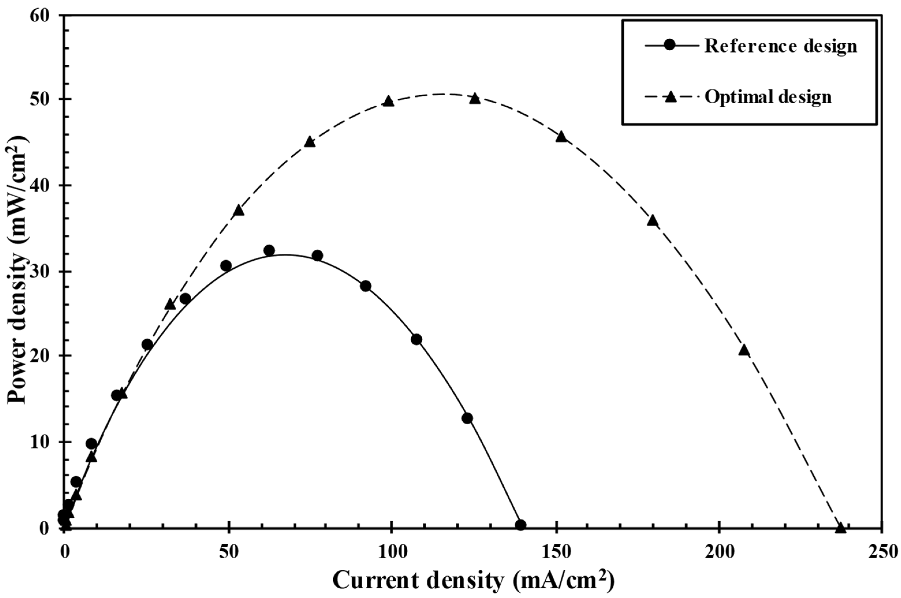
| Reference design | 1.0 | 1.0 | - | 31.88 | - | - |
| Optimal design | 1.922 | 0.815 | 49.85 | 50.24 | 0.77 | 57.6 |
Publisher’s Note: MDPI stays neutral with regard to jurisdictional claims in published maps and institutional affiliations. |
© 2022 by the authors. Licensee MDPI, Basel, Switzerland. This article is an open access article distributed under the terms and conditions of the Creative Commons Attribution (CC BY) license (https://creativecommons.org/licenses/by/4.0/).
Share and Cite
Oh, J.-H.; Vuong, T.-D.; Kim, K.-Y. Optimization of a Membraneless Microfluidic Fuel Cell with a Double-Bridge Flow Channel. Energies 2022, 15, 973. https://doi.org/10.3390/en15030973
Oh J-H, Vuong T-D, Kim K-Y. Optimization of a Membraneless Microfluidic Fuel Cell with a Double-Bridge Flow Channel. Energies. 2022; 15(3):973. https://doi.org/10.3390/en15030973
Chicago/Turabian StyleOh, Ji-Hyun, Tien-Dung Vuong, and Kwang-Yong Kim. 2022. "Optimization of a Membraneless Microfluidic Fuel Cell with a Double-Bridge Flow Channel" Energies 15, no. 3: 973. https://doi.org/10.3390/en15030973
APA StyleOh, J.-H., Vuong, T.-D., & Kim, K.-Y. (2022). Optimization of a Membraneless Microfluidic Fuel Cell with a Double-Bridge Flow Channel. Energies, 15(3), 973. https://doi.org/10.3390/en15030973