Abstract
A large number of solid particles and fibrous impurities are always entrained in the fluid transported by a sewage pump, which can easily lead to the blockage of the sewage pump. In view of this, CFD–DEM simulations were conducted in this paper to reveal the fiber clogging mechanism in the sewage pump. A CFD–DEM coupling method with a fiber model was established and verified by an experimental benchmark, i.e., the rectangular flow channel. The method was then applied to a model sewage pump to, after mesh independence tests, analyze the effects of flow rate and fiber length on fiber motion and clogging. The results showed that the position of fiber retention coincides with the position of the vortex, mainly located at the inlet of the impeller, the head of the blade, the middle of the blade, and the tongue in the pump. In the case of a low flow rate, the fiber was more likely to cause blockage in the head of the blade, and in the case of a large flow rate, the fiber would wind around the tongue in the pump. At the same flow rate, long fiber was more likely to stay on the blade’s suction surface.
1. Introduction
With the acceleration of urbanization in the world, sewage volume is also increasing continuously. At present, the total sewage discharge in the world has exceeded 400 billion cubic meters, which pollutes 5.5 trillion cubic meters of water, accounting for more than 14% of the total runoff in the world. In China, 55.465 billion cubic meters of sewage were discharged in 2019 alone. According to the National Energy Information Platform in 2022, the industry will actively practice carbon neutralization and peak carbon requirements in sewage treatment, sludge treatment and disposal, rural sewage treatment, etc. In this context, the rapid development of sewage treatment technology and equipment has also led to many new technologies and methods [1,2,3].
In sewage transport, sewage pumps have good self-priming ability, and they are widely used to transport all kinds of domestic sewage and industrial wastewater. However, the water quality in some special areas is complicated, such as eutrophication of water in some coastal areas leading to excessive growth of algae, and there is a large amount of sediment in the water in the seasonally frozen regions of the Loess Plateau [4,5]. The fluid the pumps transport is typically a solid–liquid two-phase flow containing solid suspensions. Pumps running under such miscellaneous conditions are prone to blockage or wear of internal components of the pump; thus affecting the normal operation of the pump [6,7,8,9]. In response to this, researchers have made many improvements to the pump model in order to improve the anti-clogging performance of the sewage pump [10,11,12,13]. At the same time, researchers have also carried out a large number of studies on the solid–liquid two-phase flow in the pump, aiming to provide a theoretical basis for improving the performance of the pump from the flow mechanism of multiphase flow.
At present, researchers have done a lot of research on the solid–liquid two-phase flow of pumps. Sha et al. [14] divided the energy consumption caused by the internal resistance of the vortex pump into two parts, i.e., mechanical loss and hydraulic loss, in order to study the hydraulic conveying characteristics of the solid–liquid two-phase flow vortex pump. At the same time, the performance tests of water, rapeseed, wheat, and soybean hydraulic transport were carried out on the vortex pump. Tan et al. [15] used high-speed photography technology to track the motion law of single particles in the solid–liquid two-phase flow of coarse particles in a double-paddle pump and analyzed the influence of particle size and particle density on the passing and collision characteristics of particles. Wang et al. [16] used experimental methods to study the effect of different coating thicknesses on the operating characteristics of sand-containing solid–liquid two-phase flow centrifugal pumps.
With the development of numerical simulation technology in the study of solid–liquid two-phase flow, the combination of computational fluid dynamics (CFD) and discrete element method (DEM) has been greatly developed and applied. Because the CFD–DEM coupling method can simulate particle suspension efficiently and conveniently, it has become the most promising numerical simulation method in the field of solid–liquid two-phase flow research and has been applied by a large number of researchers [17,18]. Hu et al. [19] studied the solid–liquid two-phase flow of particles with different particle sizes in a two-stage centrifugal pump by CFD–DEM coupling method. It was found that larger particles with particle sizes ranging from 10 to 30 mm could maintain better reflux performance. Li et al. [20] simulated solid–liquid two-phase flow in a centrifugal pump by CFD–DEM coupling method and carried out two-phase performance and wear tests under different flow rates and particle concentrations. The results showed that the instantaneous wear rates of the impeller, volute, and wear plate in the pump changed periodically with the rotation of the impeller. Deng et al. [21] obtained the transport characteristic curve, particle transport characteristics, and distribution characteristics of slurry in a six-stage centrifugal pump by CFD–DEM simulation. The simulation method was verified by experimental data. It was found that the particle transport in the diffuser was nonuniform, the particle transport in the diffuser was in unit of strands, and the particle transport in the pump was in pulse mode, and the particle transport characteristics in the latter stage were similar to those in the previous stage. Tang et al. [22] considered the movement characteristics of particles and simulated the solid–liquid flow in a single-channel pump by CFD–DEM coupling method. The results showed that the smaller the particles, the wider the velocity distribution range and peak value; the larger the particle, the greater the contact force.
A number of particle-based two-phase flow mechanism conclusions can be drawn from the above studies. However, the fluid medium conveyed by the sewage pump has complex impurity conditions and a wide variety of solid impurities. In addition to the usual particulate matter, it also carries a large number of fibrous impurities, which have a great impact on the pump. In recent years, with the development of CFD technology, the CFD–DEM method has been applied to fiber flow. Guo et al. [23] established a flexible fiber model based on the discrete element method (DEM) and Cundall’s bonded particle model, considering the bending, tensile, and torsional conditions of fibers under static load and dynamic vibration. Sulaiman et al. [24] established a fiber model consisting of a group of spherical beads. The transport, deformation, and buckling events of isolated elastic fibers in the Taylor–Green vortex were numerically studied, and the dynamic characteristics of filaments in uniform isotropic turbulence were studied. Imasaka et al. [25] used the CFD–DEM coupling, motion capture, and PIV methods to study the clogging mechanism of flexible fibers in pumps. The results showed that the fiber motion simulated by this method is accurate and effective.
As shown by the above research results, many scholars have studied the effect of particles in sewage pumps, but there is not enough theory about the effect of fibers in pumps. The present work studied the influence of different flow rates and fiber lengths on the fiber clogging mechanism, which is relatively basic but has not been reported. This study adopted the following methods to carry out further research: the fiber model was established by means of the CFD–DEM coupling method. Then the numerical simulation calculation was carried out and the calculation results were compared with the visualization experiment of Imasaka [25] to verify its feasibility. By changing the factors of sewage pump flow and fiber length, the transport mechanism of fibers, fiber motion characteristics, and flow field characteristics were explored. This research could provide theoretical support for the development of a sewage pump suitable for fiber suspension flow.
2. CFD–DEM Coupling Method
2.1. Governing Equation
The fluid flow in a sewage pump obeys the equations of mass conservation, momentum conservation, and energy conservation. Because the influence of heat exchange and temperature change on a centrifugal pump is negligible, and the fluid medium is regarded as incompressible fluid, it is only necessary to set out the simplified mass conservation Equation (1) and momentum conservation Equation (2).
where t is time, is the fluid density, u is the fluid velocity, F is the external mass force, and τ is the viscous stress tensor, which is expressed as
where p is the fluid pressure, is the unit tensor, = −2/3, and is the dynamic viscosity. In this study, the turbulence was described by the RANS k-ε model.
2.2. Discrete Element and Contact Model
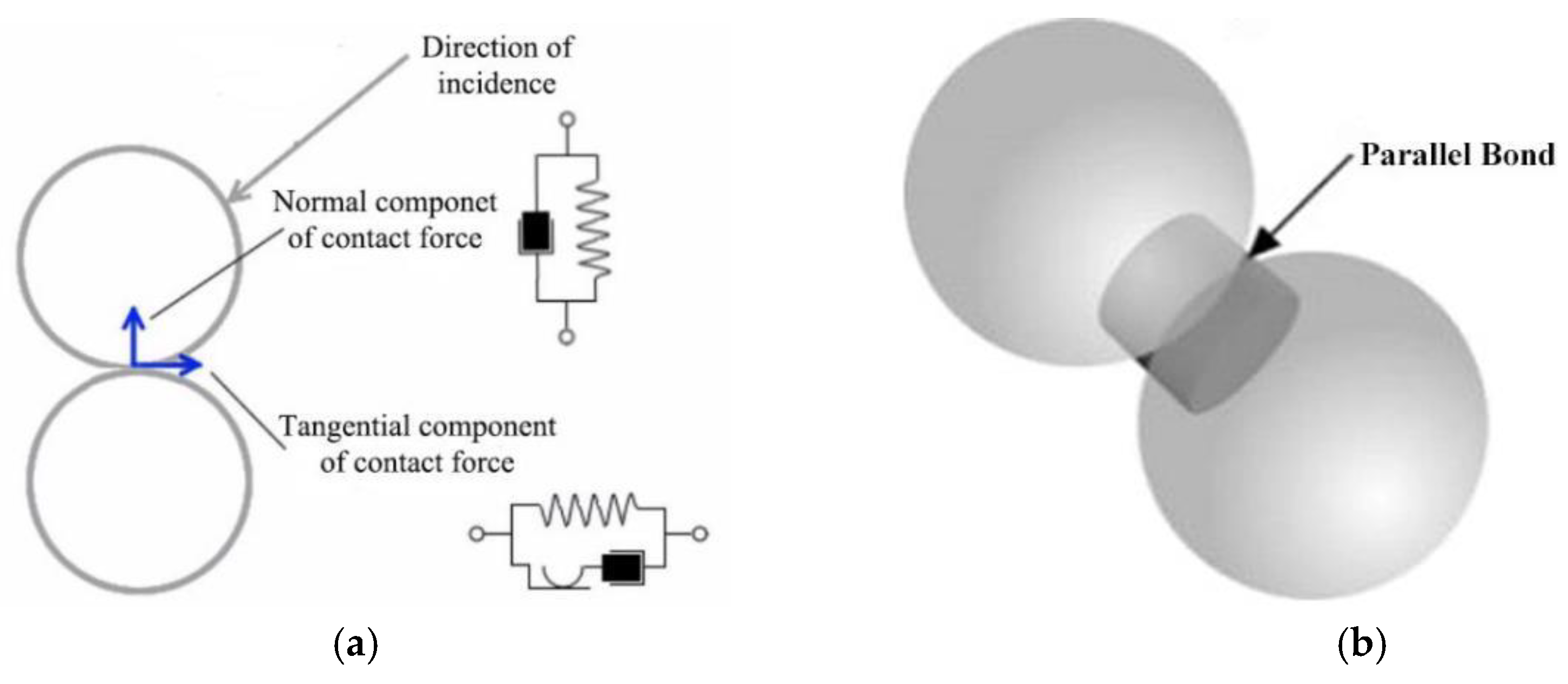
The discrete element method (DEM), constructed by Cundall and Strack [26] as an extension of the Lagrange model method, is used to model the granular fluid, e.g., sand, powder, and slurry, which is characterized by a high particle density and significant interaction between particles. The major feature of the DEM is that the interaction between particles based on the Hertz contact theory is included in the motion equation [27]. The following Hertz–Mindlin contact model is a variation of the nonlinear spring-damper contact model [28], as shown in Figure 1a, in which the contact forces are calculated using a spring-damper system:
where K is spring stiffness, d is overlapping particles, N is damping, and v is relative velocity. In addition, the subscripts n and t denote normal components and tangential components, respectively.

Figure 1.
Particle connection diagram: (a) DEM particle contact model; (b) particle bonding.
The particles are connected by massless bonds, as shown in Figure 1b. The bonds transfer force and momentum, as well as the bonding strength between particles. The forces and moments acting on the particles are calculated as follows:
where M is the moment acting on the contact surface; subscript s is the shear direction component.
2.3. The Fiber Model
In this study, several nonslip soft sphere models were used to represent fibers for numerical simulation. The soft sphere model overcomes the limitation of the number of particles contacted by the hard sphere model, allowing multiple particles to contact at the same time, and can describe a series of action processes from particle contact to rebound separation. Therefore, the soft sphere model has great advantages in simulating quasi-static problems [29].
The software combining the discrete element method (DEM) with the CFD can connect the soft sphere model and simulate the fiber. The particle model can be expanded into more complex (flexible) shapes or structures by using the soft sphere model connection. In the simulation, the particle cluster model was used to create groups to change the particles into complex shapes. As shown in Figure 2, the fiber model for numerical simulation in this study adopted DEM fibers formed by connecting spherical DEM particles through particle bonds [25], and the force between particles constituting fibers adopted the spring-damper model mentioned above.

Figure 2.
The fiber model composed of particle clusters.
2.4. Method Verification
In order to verify the established method in terms of accuracy and reliability, the numerical simulation results were compared to the visual experiments of Imasaka et al. [25]. The cross-section size of the rectangular channel was 80 × 80 mm, and the height of the channel was 280 mm as depicted in Figure 3. Five cylindrical rods that imitated the impeller cascade were arranged at even intervals in the water passage, and the diameter of the rods was 8 mm. A sketch of the grid division is also presented in Figure 3. The inlet boundary condition was enforced on the top of the channel with a mass flow rate of 8.318 kg/s. The free outflow boundary condition was enforced on the bottom of the channel, and the other faces were regarded as nonslip walls. The inlet Reynolds number was 1.304 × 10⁵ while that defined by the rod diameter was 1.304 × 10⁴. Thus, the flow was turbulent, and the RANS k-ε model was selected in this work. Details are listed in Table 1.
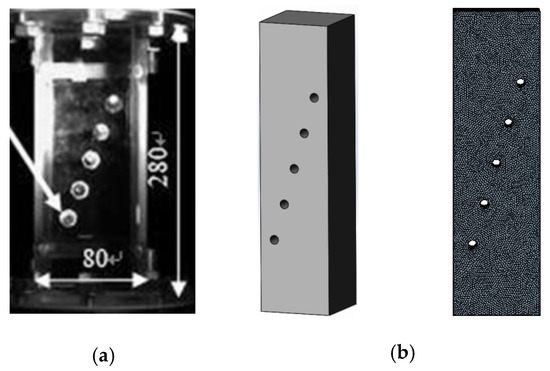
Figure 3.
(a) Rectangular channel test device [25] and (b) its griding model.

Table 1.
Computation conditions.
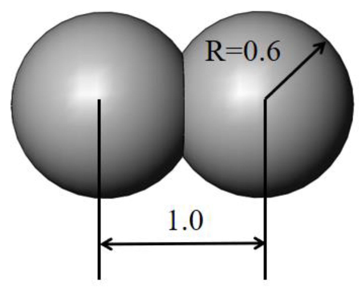
The fiber consisted of 50 DEM particles. The diameter of the particles was 1.2 mm, and the size of the overlapping region is depicted in Figure 4. The density of the fiber was 1100 kg/m3. The Hertz–Mindlin contact model was adopted between particles, and Young’s modulus was 51.7 MPa [25].

Figure 4.
Relative size of particles.
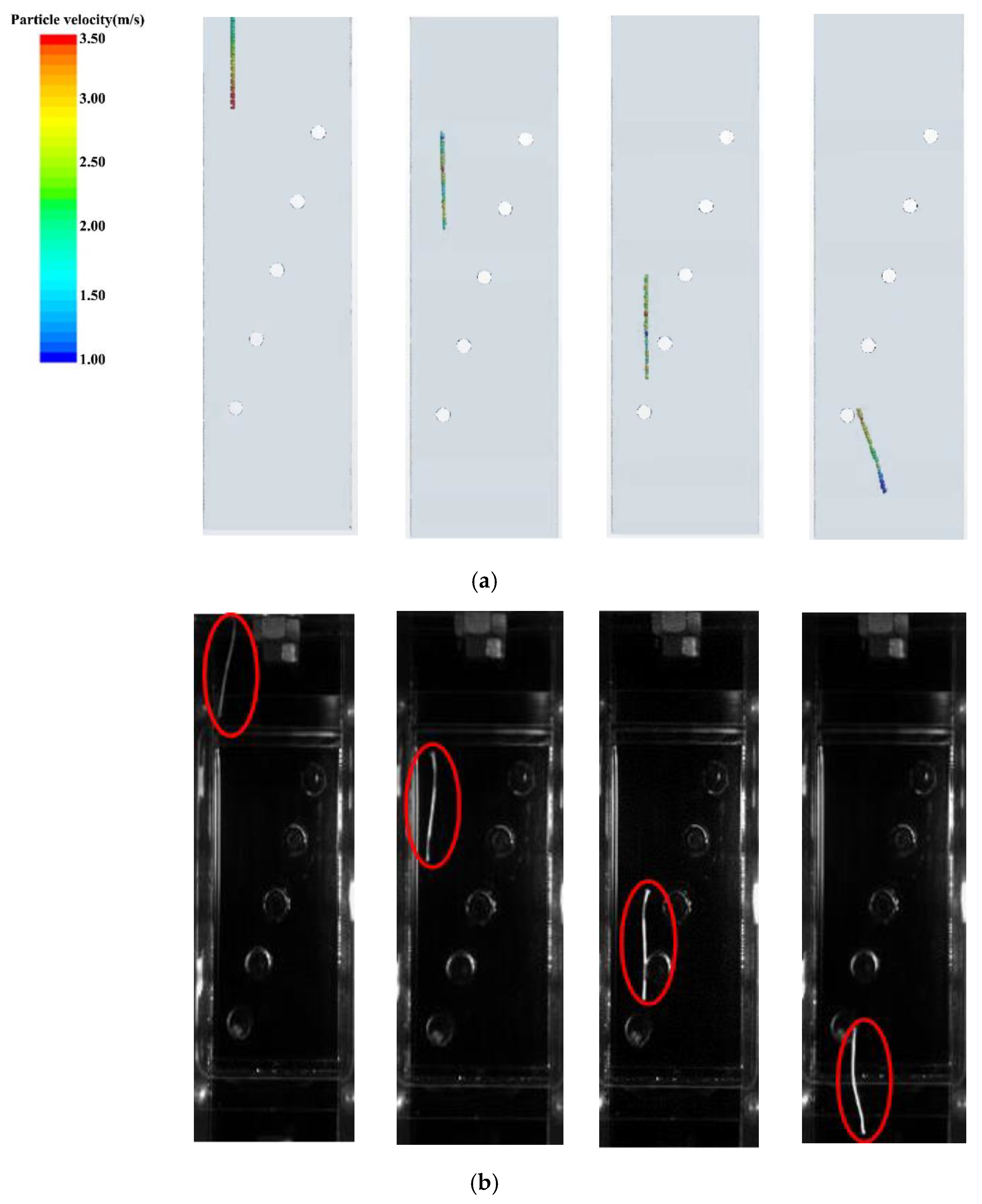
Figure 5 is a diagram of the simulation and experimental results of string motion in a straight pipe. The position of the string at different times after entering the straight tube was recorded and compared with the experimental photos at the same time. As can be seen from the contrast picture, the string only inclined when it came into contact with the cylindrical tube. Comparing the string states in (a) and (b) at the same time, it can be seen that the simulation diagram simulated the motion states in the experiment very well, which shows that the above calculation method was accurate and effective.

Figure 5.
Comparison of fiber motion: (a) simulation diagram; (b) experimental diagram [25].
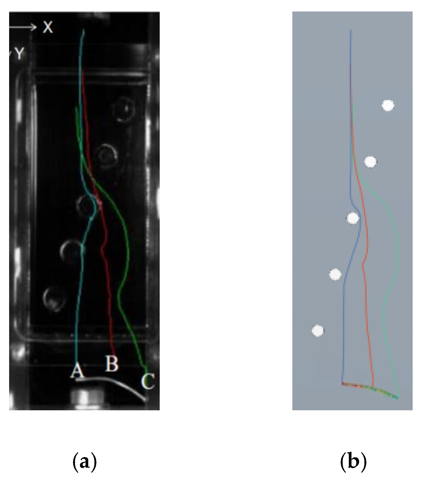
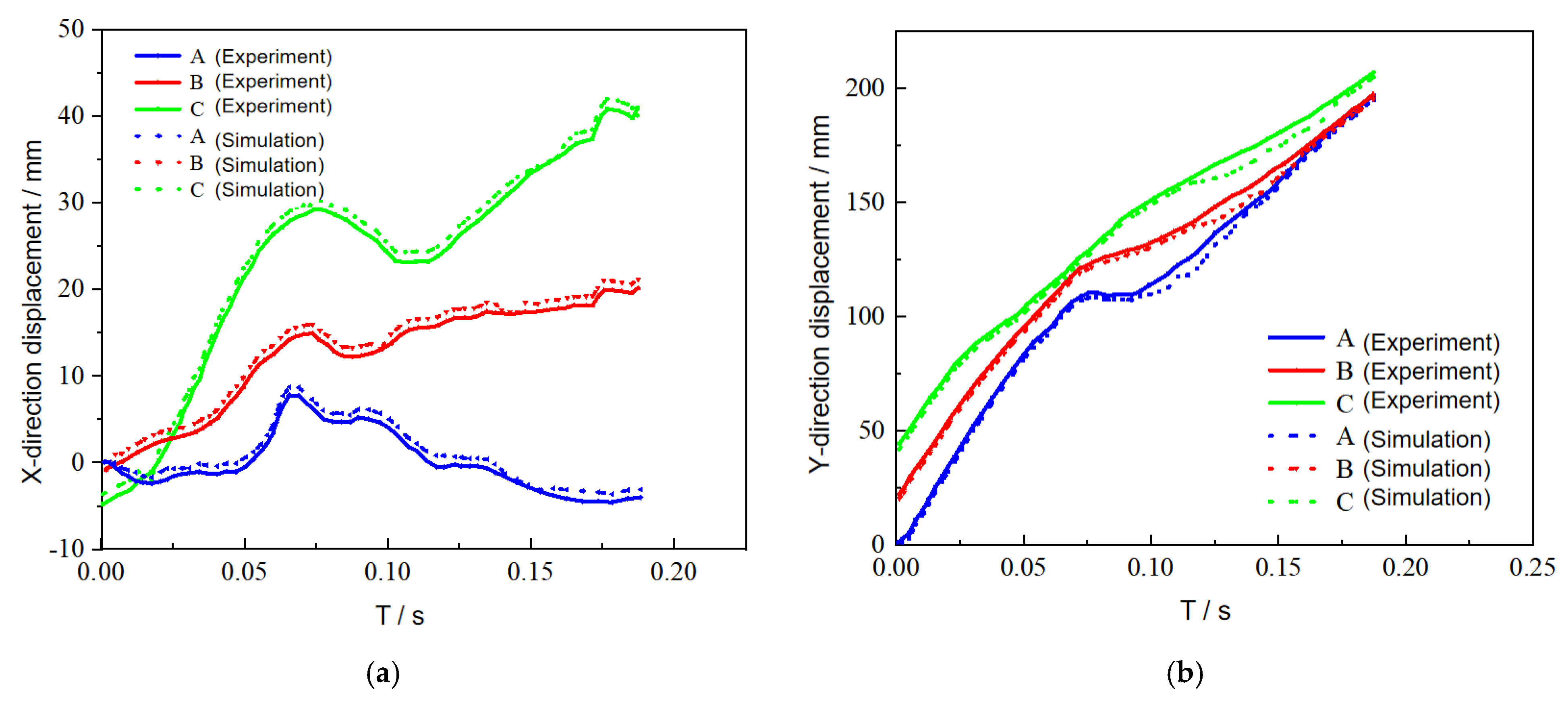
In order to further explain the rationality and accuracy of the calculation method, quantitative analysis was carried out for this example. The fiber was injected into the fluid domain from the square center position on the straight tube. In the experiment, the fiber trajectory was recorded by a high-definition camera, and the fiber trajectory was depicted in the model. As shown in Figure 6, Yamato Imasaka depicted the trajectory of the head, tail, and middle three particles of the fiber. In the simulation calculation, three monitoring points A, B, and C were set according to the experiment, and the displacement changes of the three points on both the X-axis and the Y-axis were monitored.

Figure 6.
The trajectory of the string: (a) experiment diagram; (b) simulation diagram.
The final simulation results are shown in Figure 7 below. It can be seen from the figure that points A and B were both at X = 0 at the beginning, and point C was in the negative direction of the X-axis, which means that the lower end of the fiber entered the straight tube and began to tilt. The relative position fluctuated greatly at 0.06–0.08 s, because A, B, and C touched the cylindrical obstacle rod successively at this time. At the same time, under the influence of the Karman vortex of the second cylindrical rod, the fibers began to shift to the right, and finally the fibers moved to the bottom of the flow channel. Comparing the position curves of points A, B, and C in the figure, it was observed that the simulated value of the motion state of the fiber in the straight tube was consistent with the experimental value, and the error was within 5%, indicating that the calculation method used was accurate and effective.

Figure 7.
Relative displacement of string: (a) the relative displacement of each monitoring point on X−axis; (b) the relative displacement of each monitoring point on Y−axis.
3. Numerical Method
3.1. Object
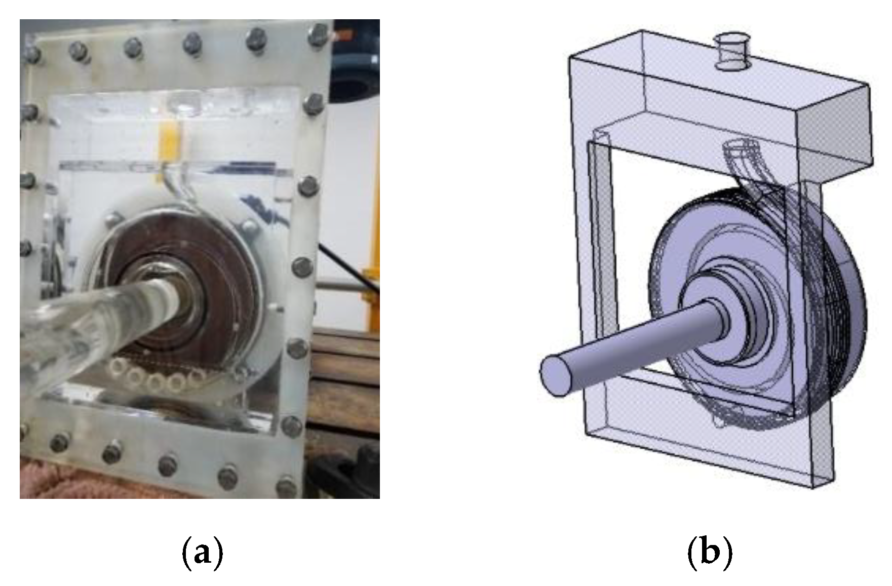
Figure 8 shows the model pump and computational fluid domain. Table 2 lists the basic design parameters of the model pump. According to the data in Table 2, the Reynolds number at the pump inlet was calculated to be 1.909 × 10⁴.

Figure 8.
Model pump: (a) physical drawing; (b) computational fluid domains.
Table 2.
Main parameters of model pump.
3.2. Grid and Boundary Conditions
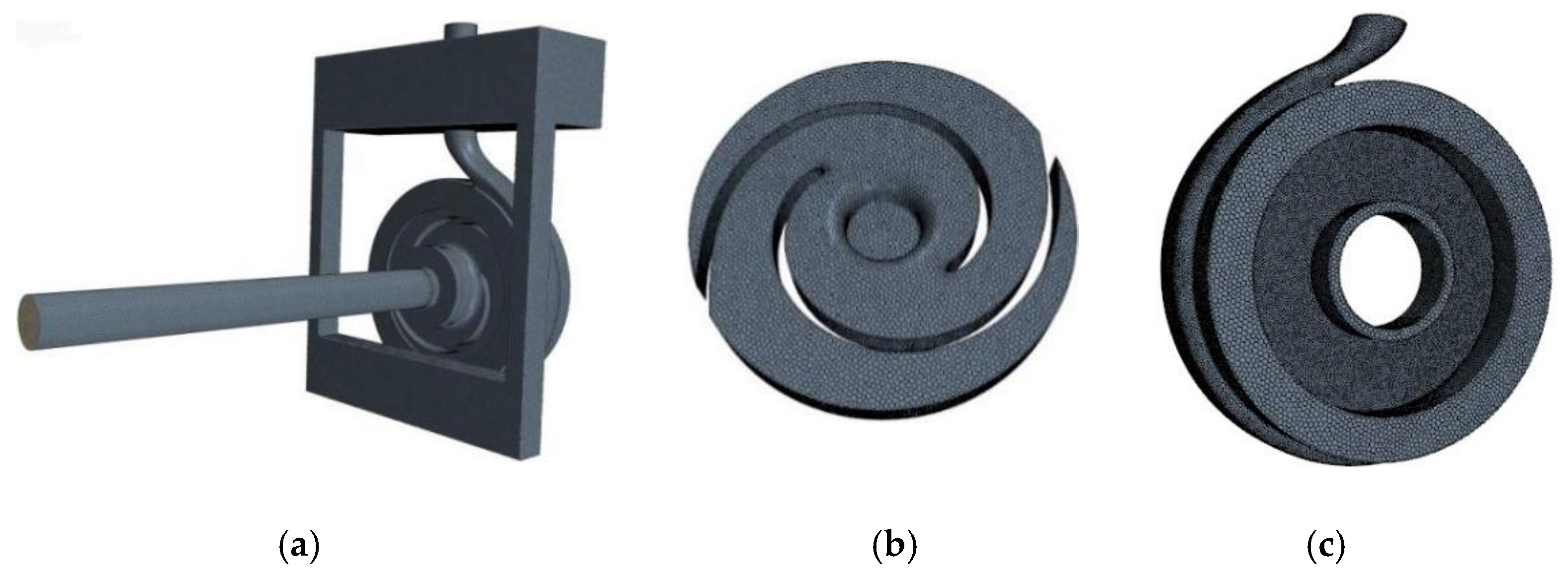
The computational fluid domain was meshed by polyhedral structured mesh. The requirement that the change of the calculated head value is less than 1% was taken as the standard for grid independence verification. The grid division scheme and verification results are shown in Table 3, and the number of selected grids was 2,208,488. Figure 9 is a schematic diagram of mesh division.
Table 3.
Meshing scheme.
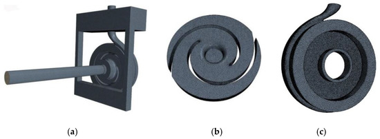
Figure 9.
Diagram of grid division: (a) total fluid domain; (b) impeller; (c) volute.
The CFD–DEM coupling method and RANS k-ε turbulence model were used to analyze the flow field characteristics of fiber in a sewage pump and the movement characteristics of fiber in a pump. The inlet was a mass flow inlet, the outlet condition was set as free outflow, and all walls were without a slip boundary. In this study, the time-step of fiber motion simulation was set to 1 × 10⁻⁵ s, the total calculation time was 2 s, and the particle diameter was 1 mm; considering the calculation cost and simulation accuracy, the number of fibers flowing into the pump per second was set to 20.
3.3. External Characteristic Experiment
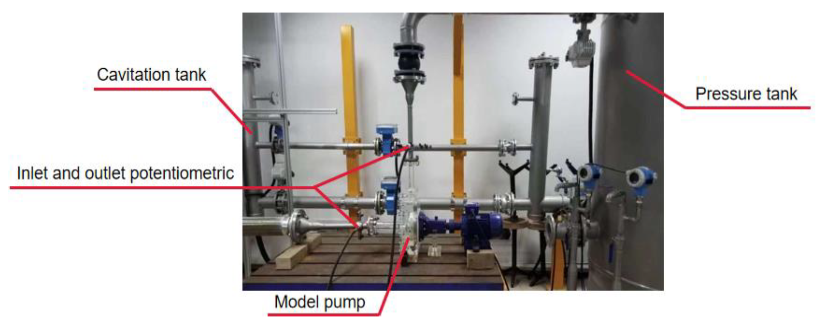
Because of the complexity of the internal details of the model pump, it was difficult to measure directly. In order to ensure the accuracy and reliability of the fluid domain model established above, it was necessary to carry out external characteristic tests to verify it. The external characteristic test device is shown in Figure 10.

Figure 10.
Experimental setup with instrumentation.
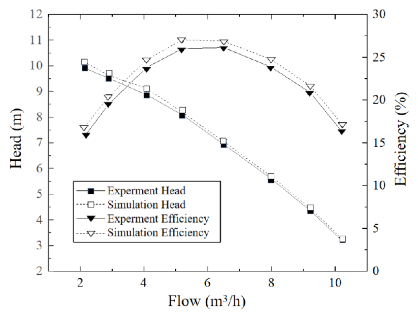
According to the above experimental and simulation settings, eight different flow conditions were selected to carry out external characteristic experiments and simulations on the model pump. The experimental values were compared with the simulation results, and the results are shown in Figure 11 below. By comparing the simulated data with the experimental data, it was seen that the numerical simulation results were basically consistent with the experimental results, and the errors were all within 3%, so the simulation results met the calculation requirements.
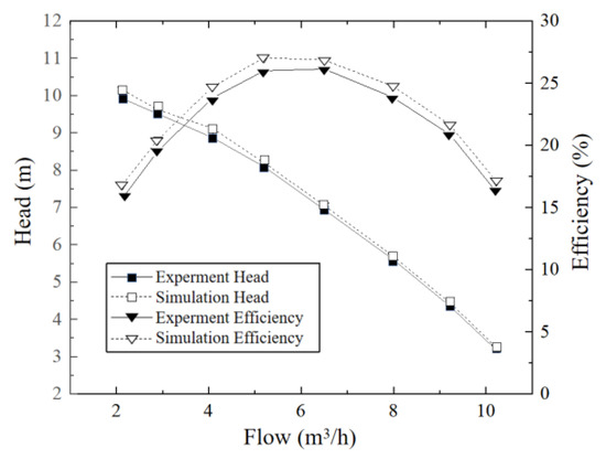
Figure 11.
Comparison of numerical and experimental results.
4. Fiber Motion Analysis
There are many factors that affect the blockage caused by fibers in sewage pumps, such as the structure of pumps, operating conditions, fiber shape, etc. However, due to the limited time and cost of research, only the influence of flow conditions and fiber length has been discussed. Different flow conditions will change the complexity of the internal flow field. The greater the flow rate, the more obviously the fiber is affected by the fluid, and the fiber will show different flow conditions. Fiber shape is also an important factor affecting blockage. It is generally recognized that long fibers are more likely to cause blockage in pumps, but the specific clogging mechanism is difficult to know. Based on the above facts, the clogging problem of sewage pumps was studied from different flow conditions (0.8Q, Q, and 1.2Q) and different fiber lengths (80, 120, and 160 mm).
4.1. Trajectory Analysis
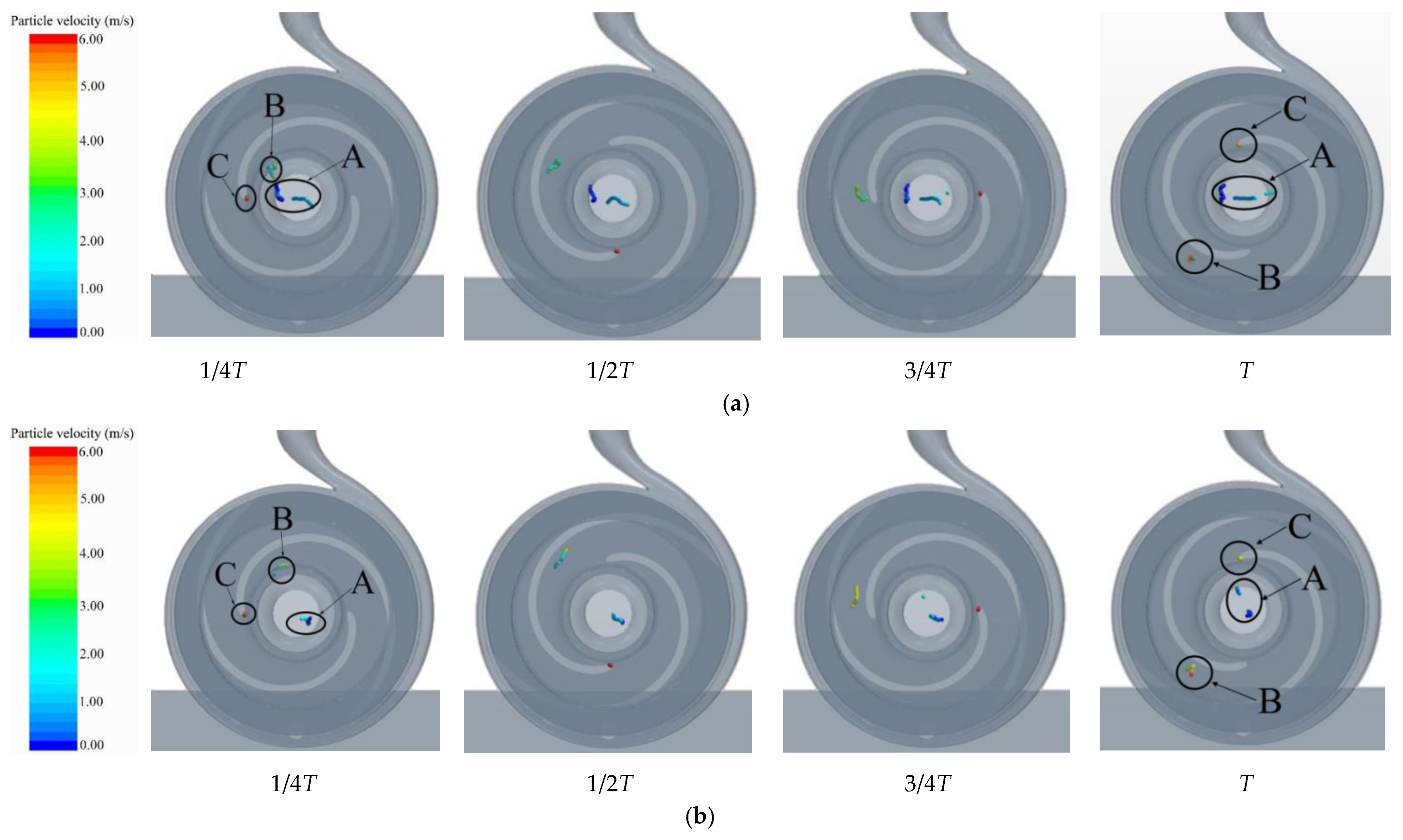
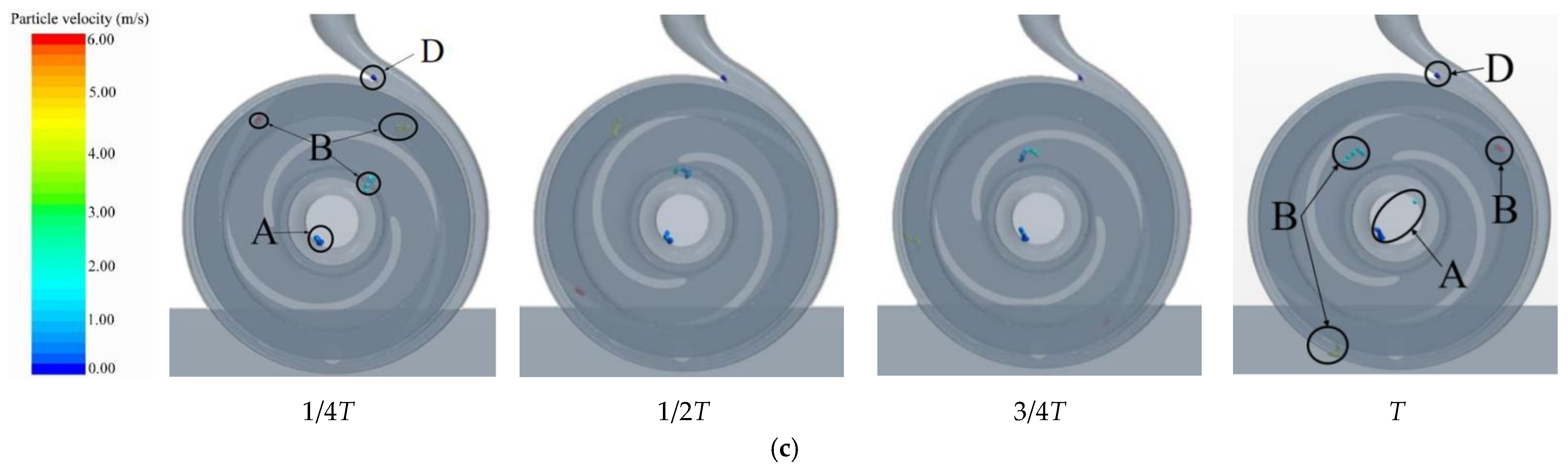
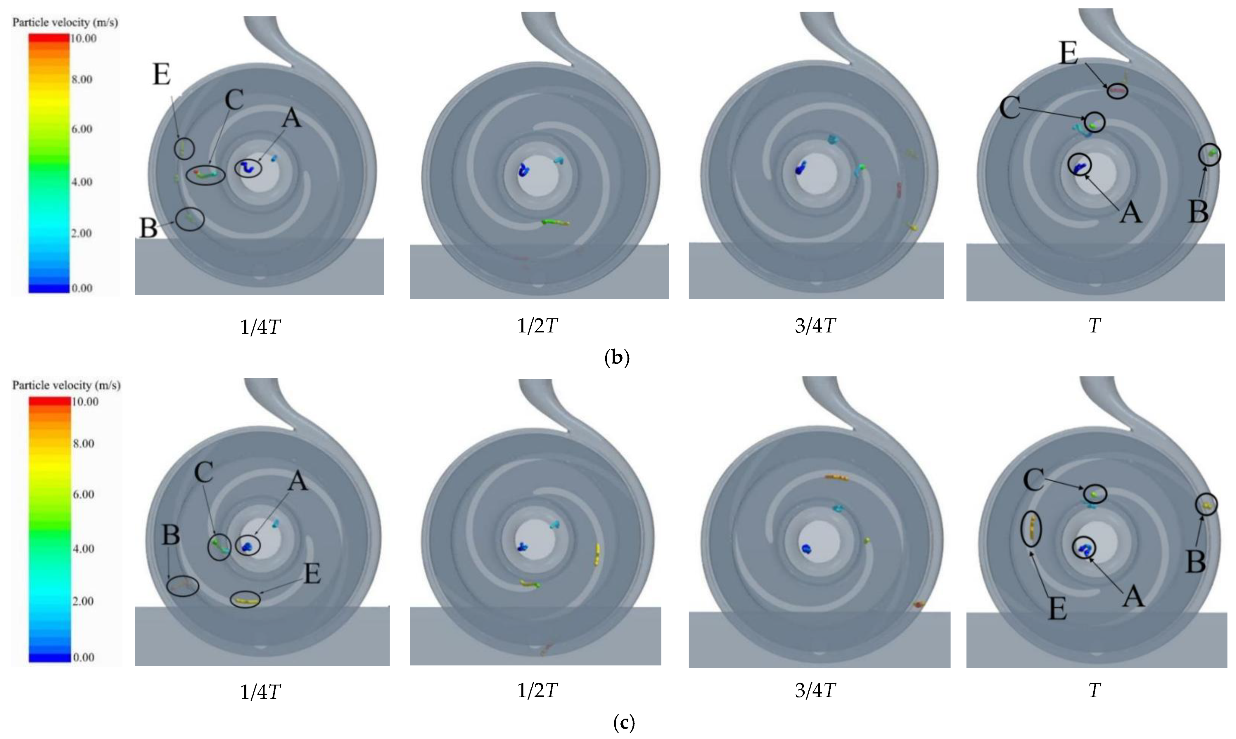
Figure 12 shows the fiber distribution in the pump at 1/4T, 1/2T, 3/4T, and T times in the same cycle under three working conditions. The fiber length was set to 80 mm, and the simulation set of fiber flow rate was 20/s.
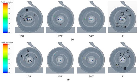
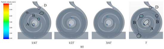
Figure 12.
Diagram of fiber movement in sewage pump at different flow rates. (a) 0.8Q; (b) Q; (c) 1.2Q.
As can be seen from the figure, fibers easily remained at the inlet of the flow channel, such as A in the figure, which was very similar to the distribution of particles in the pump [30]; the B fibers moved smoothly to the tail of the blade; under the flow rate of 0.8Q and Q, the fibers easily remained in the impeller head, such as C in the figure; when the flow rate increased to 1.2Q, the fibers did not stay at the head of the blade, but they did stay at the tongue of the volute. The above analysis of different flow rates showed the influence of flow rates on the position of fiber blockage: under a small flow rate, fibers tended to stay at the blade head; under the condition of a large flow rate, the fibers were more likely to stay at the tongue of the volute.
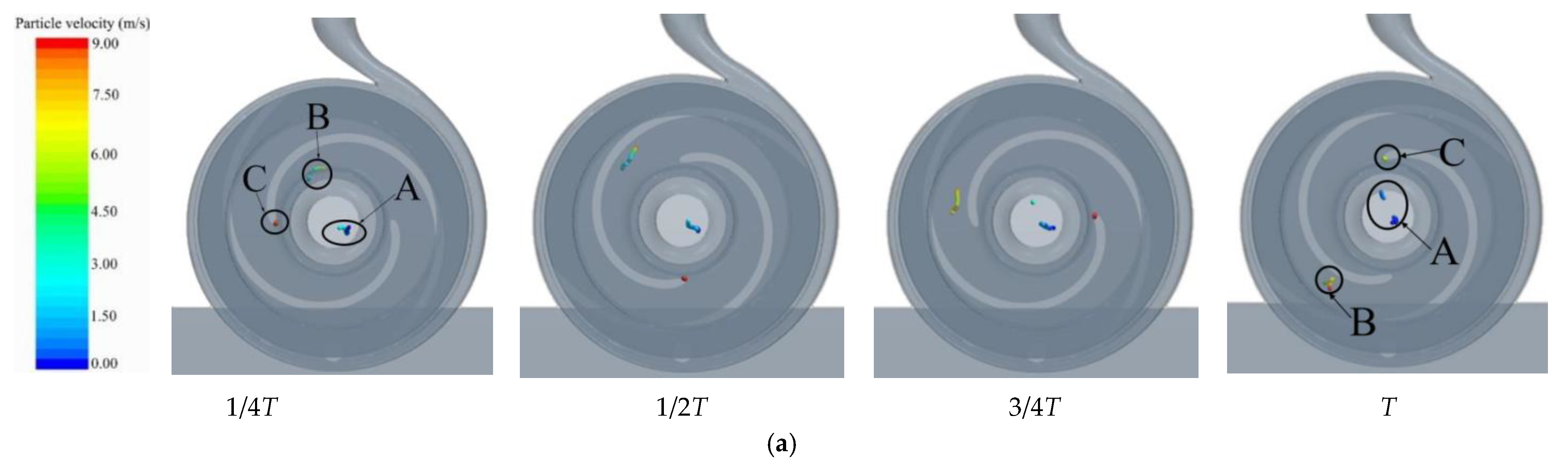
In the condition of rated flow rate, the fiber length was changed, and the fiber trajectory was analyzed again, and the fiber lengths were selected as 80, 120, and 160 mm.
Figure 13a is the diagram of fiber motion tracking with different lengths under rated flow condition. It can be seen from the diagram that no matter how the fiber length changed, there were three typical fibers: A, B, and C. When the fiber length increased, the fiber not only caused blockage at the inlet and head of the impeller, but also adhered to the middle position of the suction surface of the blade, as shown with E in Figure 14b,c. This phenomenon was quite different from the movement of particles in the pump. For particles, regardless of the flow rate, most of them are distributed on the pressure surface of the blade rather than gathering on the suction surface [30]. Through observation, it was found that although 120 and 160 mm fibers were attached to the middle of the suction surface of the blade, the attachment positions of the two fibers were still obviously different: the 120 mm fibers were closer to the tail of the blade, and the 160 mm fibers were closer to the head of the blade. In addition, because the shorter 80 mm fibers would not adhere to the leaves, it can be inferred from the position of the binding E fibers that long fibers are more likely to stay on the leaves.
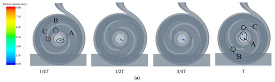

Figure 13.
Diagram of fiber movement in sewage pump with different fiber lengths. (a) 80 mm; (b) 120 mm; (c) 160 mm.
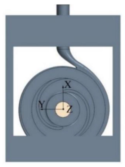
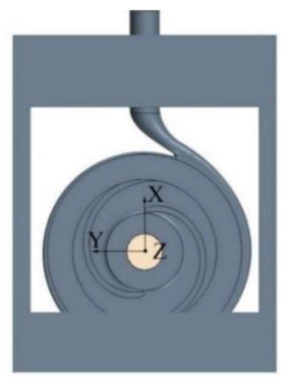
Figure 14.
Coordinate axis position.
4.2. Position Analysis
In order to further study the motion mechanism of the three typical fibers A, B, and C, the movement changes of the three fibers were quantitatively analyzed under suitable working conditions. Because the three kinds of fibers under the 0.8 Q were relatively small from the force of fluid, and their moving speed was slow, which was easier to distinguish on the graph, the 0.8 Q flow rate was selected for analysis. Figure 14 is a three-dimensional coordinate system established with the impeller center as the origin, and the coordinate changes of fibers represent the position changes of the fibers in the process of movement, so as to obtain the position change law of fibers.
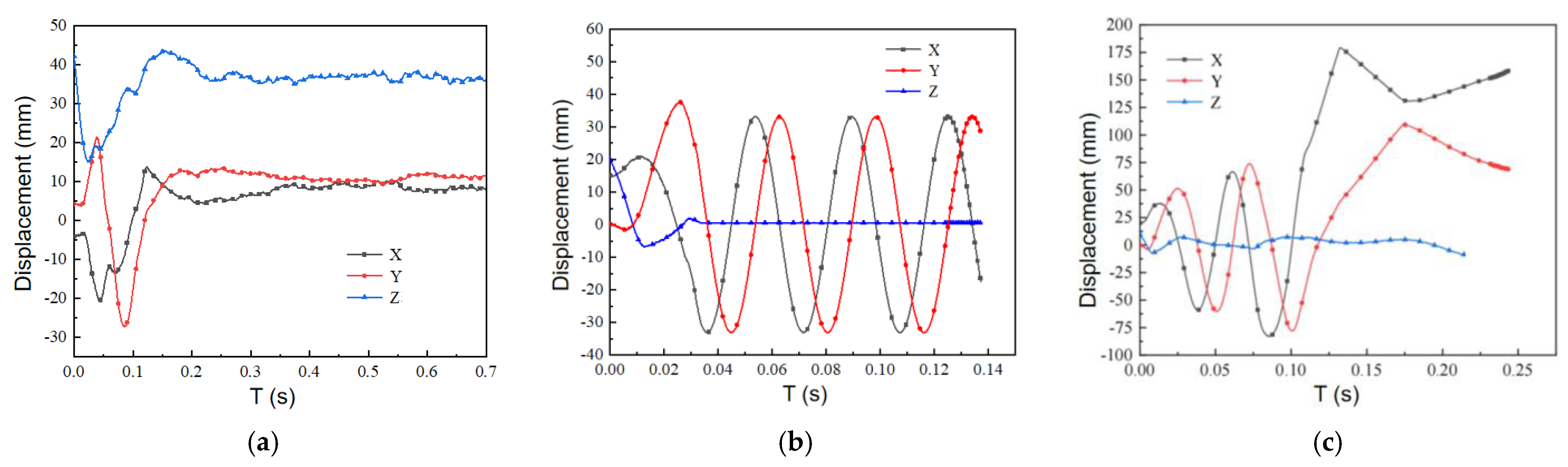
Figure 15a shows the movement position change diagram of A-type fibers in the pump; that is, fibers wandering at the impeller inlet. It can be seen from the figure that after the A-type fiber entered from the inlet, the displacement in the Z-axis direction decreased first, which showed that the A-type fibers first moved towards the center of the impeller. When moving to 15 mm on the Z-axis, the fiber began to rebound, and the displacement along the X- and Y-axes also changed abruptly, which indicated that the fiber encountered a reflux vortex at this place. After 0.2 s, the displacement along the X-, Y-, and Z-axes tended to be stable, and the displacement positions were 7, 10, and 35 mm, respectively. Therefore, it could be judged that the reflux vortex at the inlet of the impeller in the pump appeared near this position.
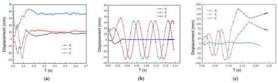
Figure 15.
Variation of fiber displacement: (a) A-type fibers; (b) B-type fibers; (c) C-type fibers.
Figure 15b shows the movement position change of B-type fibers in the pump. After entering the flow channel, B-type fibers flowed normally and moved with the rotation of the impeller, finally flowing out from the outlet. In the direction of the X- and Y-axes, the fibers changed periodically in the early stage of movement. During this period, the fibers moved with the rotation of the impeller in the impeller passage, and the peak displacement in the direction of the X- and Y-axes gradually increased, which showed that the fibers moved to the periphery and finally flowed out from the outlet. While in the direction of the Z-axis, we can see that the fiber always moved around Z = 0 mm. The normal outflow time of the fibers was about 0.13 s.
Figure 15c shows the movement position change of C-type fibers in the pump. C-type fibers stayed at the blade head after entering the impeller. It can be seen from the figure that the displacement of fibers in the Z-axis direction first decreased and then increased, finally stabilizing at about Z = 0 mm. C-type fibers tended to move in the Z-axis neutral position after entering the flow channel, which was caused by the fast flow velocity; as can be seen from the displacement changes in the X- and Y-axes, the fibers moved to the blade head after entering the impeller, and it can be seen from the peak movement that the retention position was 34 mm away from the center point. Analysis of the diagram showed that once the fibers were caught at the blade head, it was difficult to change their motion and allow them to flow smoothly out of the pump.
When analyzing the trajectory of fibers with different lengths, it was found that the length would change the position of the fibers staying in the sewage pump. In order to further analyze this phenomenon, the average position changes of different fibers were quantitatively analyzed.
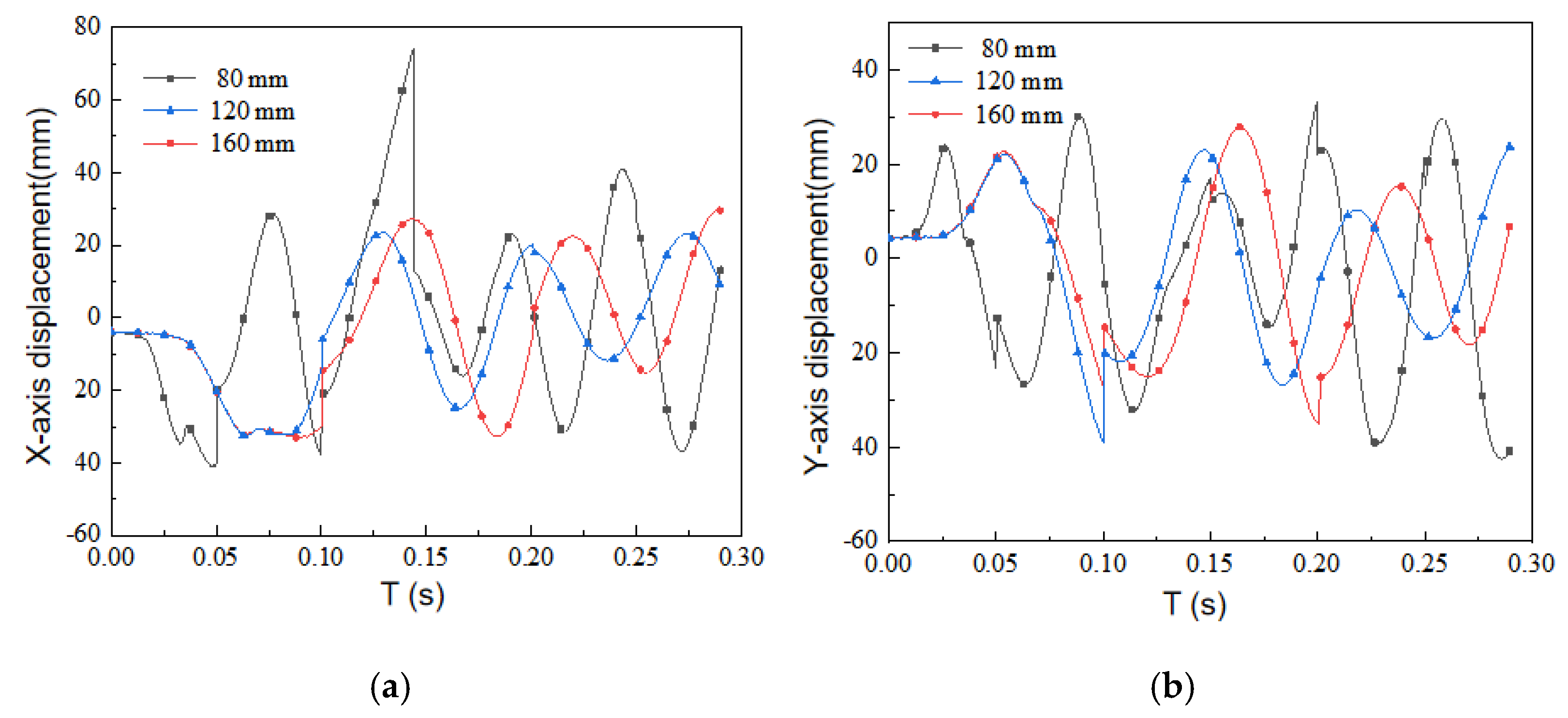
Figure 16 is a graph of the position of fibers with three lengths on the X-axis and the Y-axis with time. The abrupt change in the curve was due to the change in the average position of the fibers caused by the normal flow of fibers in and out of the pump. Compared with (a) and (b), it was found that the 80 mm fibers always took the lead in position change, entered the flow channel faster, and made a circular motion with the rotation of the impeller; however, the trajectories of the 120 and 160 mm fibers were very consistent before they entered the impeller passage smoothly, and they changed only after entering the impeller passage. Comparing the motion of the 120 and 160 mm fibers, it was found that the circular motion time of the 160 mm fibers was longer, i.e., the smooth outflow time of the 160 mm fibers was longer, which led to a large number of fibers accumulating and forming a blockage in the pump when the fiber flow rate was too high.
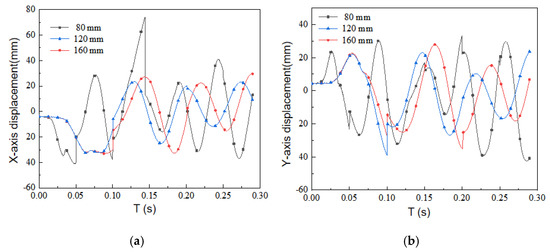
Figure 16.
Fiber displacement: (a) X-axis displacement; (b) Y-axis displacement.
4.3. Velocity Vector Analysis
The fluid medium conveyed in the fluid machinery generally has a fast flow rate, and the internal flow state is relatively complex, which will generate a large number of vortices, thereby affecting the flow stability. Since the position of the vortex could be seen intuitively from the velocity vector analysis, this section analyzes the velocity vector to obtain the relationship between the vortex and the fiber blockage. At the same time, the vorticity was analyzed in the next subsection to obtain further relevant conclusions. The reflux vortex was obviously affected by the flow rate and was hardly affected by the fiber length, so only different flow conditions were analyzed here.
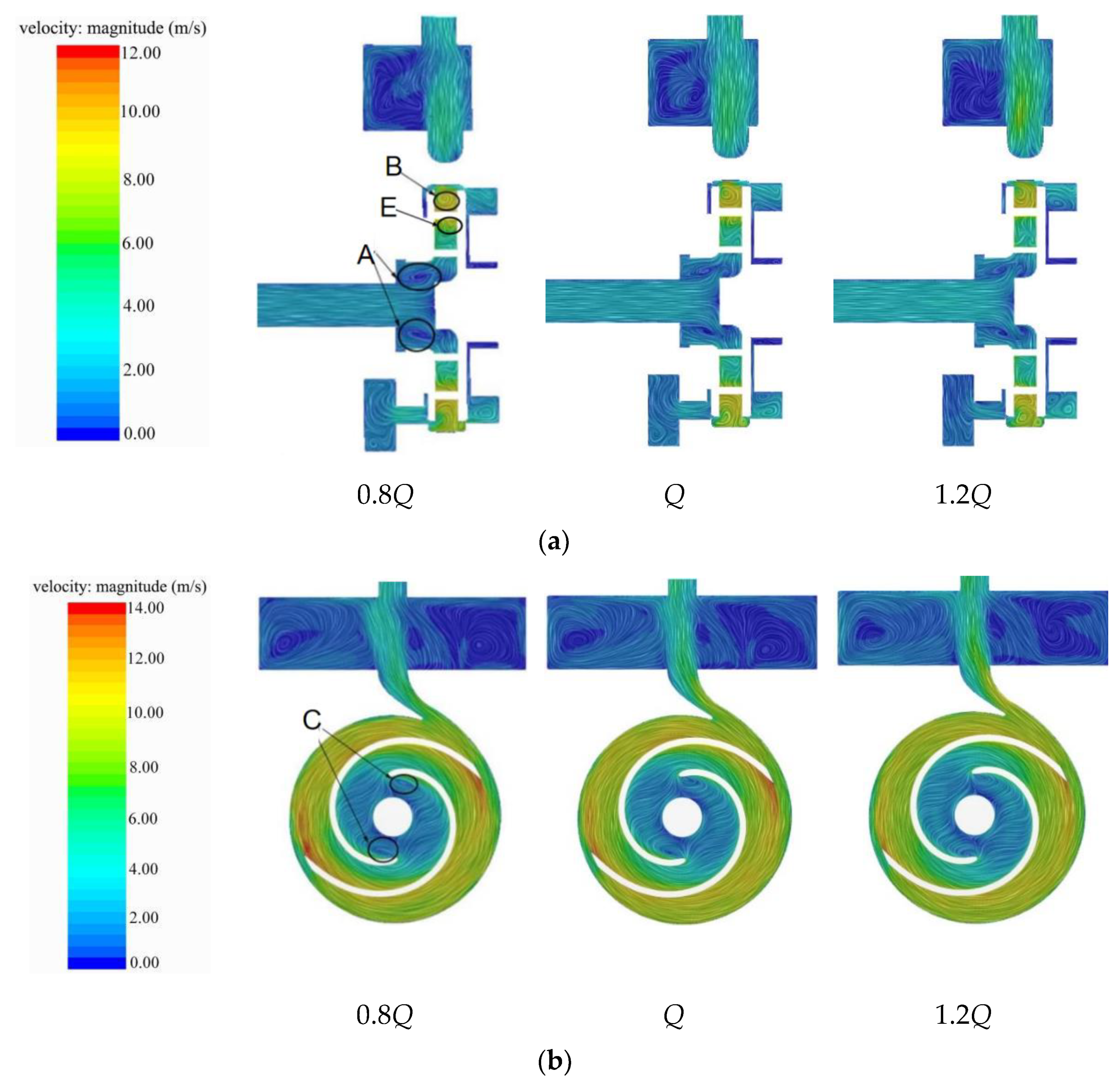
Figure 17 is a velocity vector diagram under different flow rates. From the diagram, it can be seen that there are a large number of backflow vortices in the pump, among which the four vortices A, B, C, and E in the diagram mainly affected the fiber movement. In Figure 17a, because of the existence of stall vortex A, fibers wandered at the impeller inlet, and long-term accumulation led to blockage at the impeller inlet; the recirculation vortex B appeared between the pressure surface of the blade and the wall of the volute, where the flow velocity along the outer direction of the volute was larger, and the fibers involved in it flowed along the inner wall of the volute; the recirculation vortex E appeared on the suction surface of the blade. Through the analysis of the fiber trajectory before, it was known that long fibers were easily caught here. With the increase of flow rate, the stall vortex A began to weaken, and the risk of fiber blockage at the impeller inlet decreased; the scope of reflux vortex B enlarged with the increase of flow rate, and it was easier to involve fibers in it. Therefore, when fibers flowed through the diaphragm tongue, they were easily stuck on the volute tongue under the action of reflux vortex B; the reflux vortex C also showed a weakening trend with the increase of flow rate, which indicated that increasing the flow rate can reduce the risk of fiber retention here.

Figure 17.
Velocity vector diagram: (a) XZ section; (b) XY section.
Figure 17b is the velocity vector diagram of the XY section of the impeller. It can be seen from the diagram that there were two symmetrical reflux vortices C at the head of the suction surface of the blade head, which was one of the reasons for fiber adsorption onto the suction surface of blade.
4.4. Vorticity Analysis
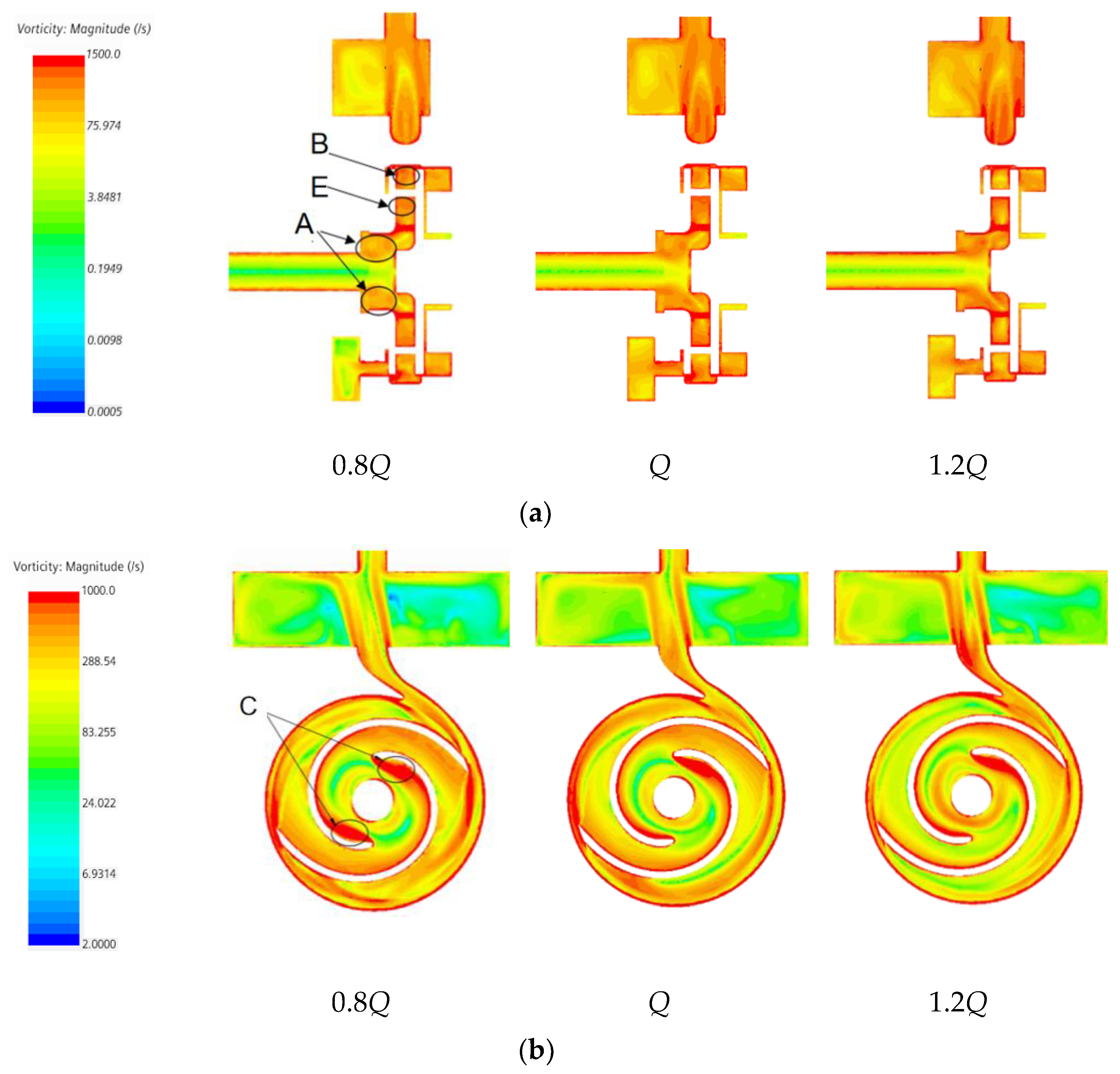
In order to further study the relationship between vortex and fiber blockage in the pump, this section quantitatively analyzes it by vorticity. Figure 18 is a vorticity diagram under different flow rates. It can be seen from Figure 18b that with the continuous increase of flow rate, the overall vorticity intensity in the pump began to weaken gradually, but there were still several regions with strong vorticity. From the analysis of Figure 18a, it can be seen that after the fluid medium entered from the inlet, it experienced the first obvious vorticity change in region A, that is, the place where the stall vortex exists in the upper section, so fiber blockage easily occurred. Secondly, region E and region B were the tail of the suction surface of the blade and the tongue of the volute, respectively, and there was also a strong vortex, which easily trapped fibers in it. From the analysis in Figure 18b, it is obvious that there was a very strong vortex at the head of the suction surface of the blade, which easily involved fibers. This was also the reason why fibers stayed on the suction surface of the blades. In addition, by comparing the vorticity in region C under different flow rates, it was clearly observed that with the increase of flow rate, the range of region C began to decrease. It can be seen from the above analysis that increased flow rate can alleviate the fiber blockage in region C, which is basically consistent with Zhang et al. [31].
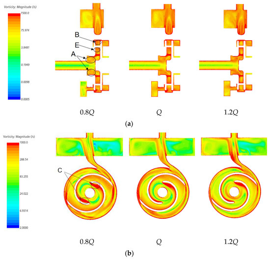
Figure 18.
Vorticity diagram of different flow sections: (a) XZ section; (b) XY section.
4.5. Pressure Fluctuation Analysis
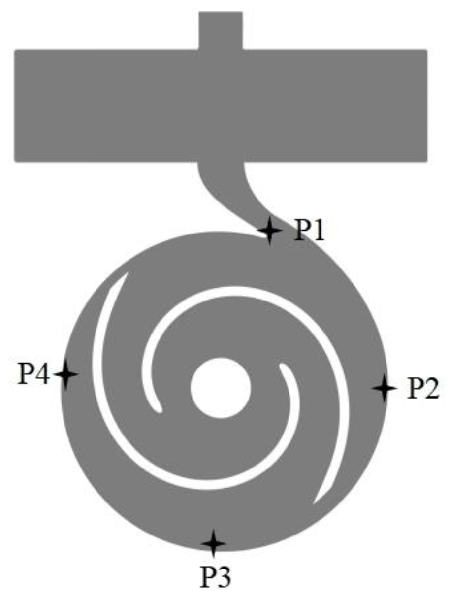
In order to further analyze the characteristics of vortex generation in the internal flow field, pressure fluctuations at detection points were analyzed. Since pressure was only slightly affected by changes in fiber length, only the effect of different flow rates was discussed. Figure 19 shows the distribution of monitoring points, set to P1, P2, P3, and P4.
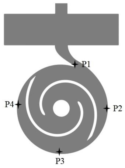
Figure 19.
Diagram of monitoring point distribution.
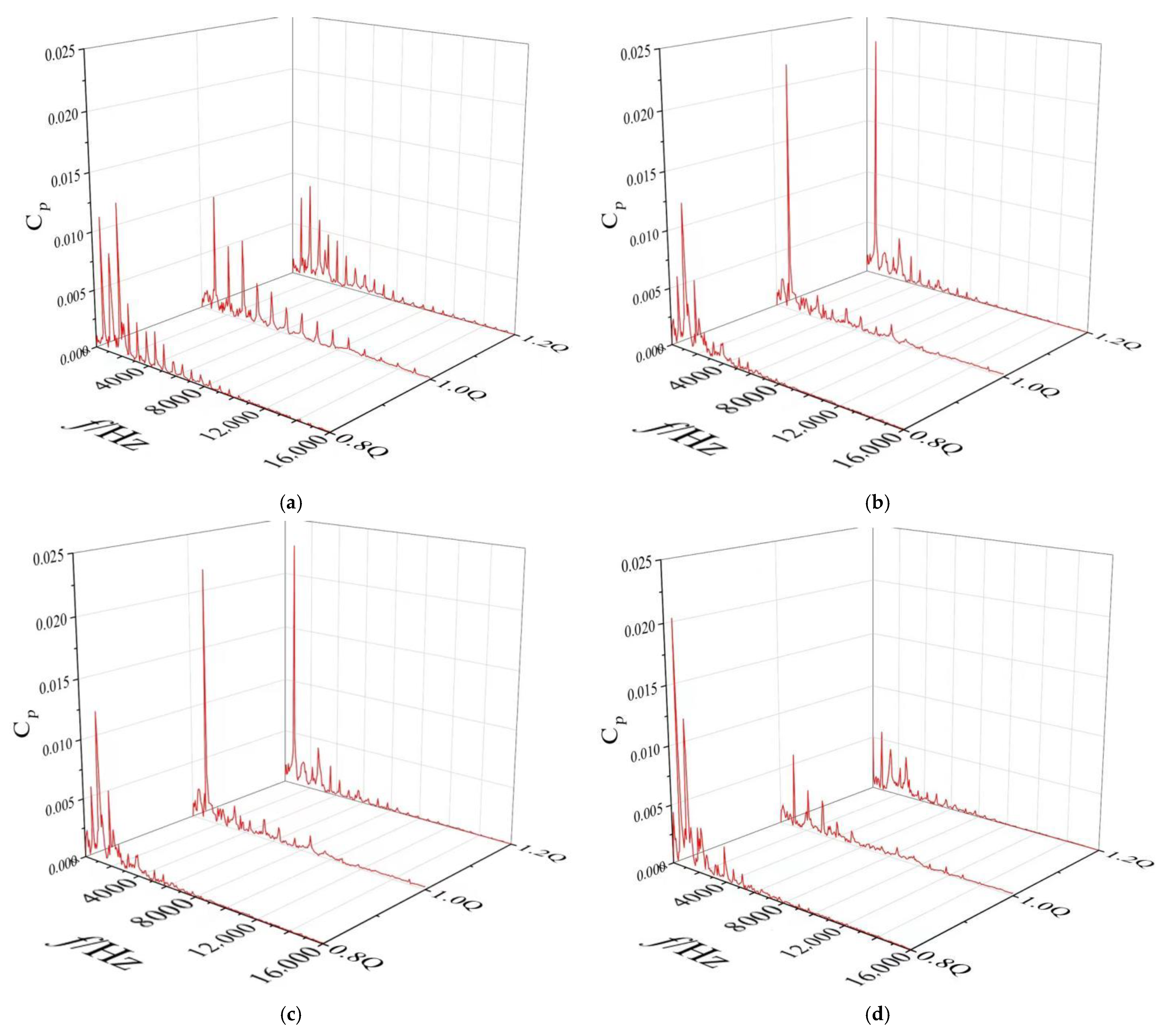
The pressure fluctuation diagrams of monitoring points under different flow conditions were compared transversely, as illustrated in Figure 20. The pressure fluctuation amplitude of P1, P3, and P4 decreased with the increase of flow rate, while that of P2 increased. The pressure fluctuation amplitude of P2 nearly doubled from small flow to rated flow. At P1, the pressure fluctuation amplitude was relatively small due to the accumulation and development of bubbles at the tongue where the fluid was impacted. The stall vortex development and fusion at P2 reached the maximum, and the flow was the most disordered at this time, resulting in a large pressure pulsation. At P3, the pressure fluctuation amplitude under small flow condition was larger than that at P2, and with the increase of flow, the amplitude of the pressure pulsation was smaller than that at P2 because the stall vortex area was larger under the small flow condition and moved in the opposite direction of the impeller. Under the rated flow and large flow, the stall vortex did not change greatly with the increase of flow. It was the largest at P2 and gradually decreased along the opposite direction of the impeller rotation. Therefore, the flow also tended to stabilize from disorder, and the pressure on the volute wall gradually decreased.
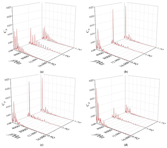
Figure 20.
Comparison of pressure fluctuation at monitoring points under different flow conditions. (a) P1 (b) P2 (c) P3 (d) P4.
5. Conclusions
At present, most of the solid–liquid two-phase flow in sewage pumps is based on solid particles, but less research has been done based on fibers. In this study, in order to better study the effect of fiber impurities on the clogging mechanism of sewage pumps, the CFD–DEM coupling method was used to study the motion characteristics of fiber impurities in self-priming sewage pumps. Specifically, after a reasonable verification, this study simulated and compared the fiber motion by changing the flow rates and fiber length at first, and then analyzed and summarized the fiber motion characteristics and flow field motion characteristics obtained by the simulation. The main conclusions were as follows:
- Influence of flow rate on the movement of fiber in the pump: under the condition of small flow rate, fiber was easily caught at the impeller inlet and blade head, which caused blockage; under large flow conditions, fibers were easily trapped at the impeller inlet and wound up at the volute tongue;
- The influence of fiber length on the movement characteristics of the pump: First, the long fiber more readily adhered to the suction surface of the blade. Second, it took longer to flow out from the pump, which made it more likely to cause fiber accumulation and blockage in the pump;
- Vortex in flow field could easily cause fiber clogging, and the main positions were at the impeller inlet, the blade head, and the middle of the blade suction surface. Concerning the position of the vortex, the vortex at the impeller inlet was the place where fiber was most easily blocked;
- From the analysis of vorticity intensity, it was seen that the vorticity intensity at the inlet of the impeller, the suction surface of the blade, and the volute tongue was large, which made the vorticity more likely to cause fiber blockage. However, with the increase of flow rate, the vorticity in some regions began to decrease.
Author Contributions
Conceptualization, S.Z. and C.Y. (Chaojie Yang); methodology, S.Z. and C.Y. (Chaoshou Yang); investigation, C.Y. (Chaojie Yang), C.Y. (Chaoshou Yang) and Z.S.; writing—original draft, C.Y. (Chaojie Yang); writing—review and editing, S.Z. and M.C.; supervision, M.C.; funding acquisition, S.Z. and M.C. All authors have read and agreed to the published version of the manuscript.
Funding
This research is funded by the National Natural Science Foundation of China (Grants No. 51976193); the Basic Public Welfare Research Project of Zhejiang Province (Grants No. LGG22E060011); and the State Key Laboratory of Clean Energy Utilization (Project No. ZJUCEU2020004). The authors are also grateful to the Advanced Computing East China Sub-center for providing the computational resources.
Institutional Review Board Statement
Not applicable.
Informed Consent Statement
Not applicable.
Data Availability Statement
Not applicable.
Conflicts of Interest
The authors declare no conflict of interest.
References
- Zhang, L.; Wang, L.; Zhang, Y.; Wang, D.; Guo, J.; Zhang, M.; Li, Y. The performance of electrode ultrafiltration membrane bioreactor in treating cosmetics wastewater and its anti-fouling properties. Environ. Res. 2022, 206, 112629. [Google Scholar] [CrossRef] [PubMed]
- Tomassi, G.; Romano, P.; Di Giacomo, G. Modern Use of Water Produced by Purification of Municipal Wastewater: A Case Study. Energies 2021, 14, 7610. [Google Scholar] [CrossRef]
- Marouek, J.; Marouková, A. Economic Considerations on Nutrient Utilization in Wastewater Management. Energies 2021, 14, 3468. [Google Scholar] [CrossRef]
- Fang, X.; Wang, Q.; Wang, J.; Xiang, Y.; Wu, Y.; Zhang, Y. Employing extreme value theory to establish nutrient criteria in bay waters: A case study of Xiangshan Bay. J. Hydrol. 2021, 603, 127146. [Google Scholar] [CrossRef]
- Xu, J.; Lan, W.; Ren, C.; Zhou, X.; Wang, S.; Yuan, J. Modeling of coupled transfer of water, heat and solute in saline loess considering sodium sulfate crystallization. Cold Reg. Sci. Technol. 2021, 189, 103335. [Google Scholar] [CrossRef]
- Zhao, B.-T.; Ye, B.-B.; Tao, R.-H.; Cao, G.-W.; Wu, F. Design of new non-clogging self-priming sewage pump. Mech. Electr. Eng. Mag. 2012, 29, 806–809. [Google Scholar]
- Moloshnyi, O.; Szulc, P.; Molinski, G.; Sapozhnikov, S.; Antonenko, S. The analysis of the performance of a sewage pump in terms of the wear of hydraulic components. J. Phys. Conf. Ser. 2021, 1741, 012015. [Google Scholar] [CrossRef]
- Liu, J.H.; Zhu, M.Y. Simulation Study on Attrition to Centrifugal Sewerage Pump. Key Eng. Mater 2011, 1244, 474–476. [Google Scholar] [CrossRef]
- Cheng, C.; Shi, W.D.; Zhang, D.S.; Cao, W.D.; Xing, J. Numerical simulation of solid-liquid two-phase turbulent flow in swept-back sewage centrifugal pump. J. Drain. Irrig. Mach. Eng. 2015, 33, 116–122. [Google Scholar]
- Liu, J.; Shi, W.; Kong, F.; Pan, Z. Research on multifunctional non-clogging sewage pump. Trans. Chin. Soc. Agric. Eng. 2003, 19, 126–129. [Google Scholar]
- Zhu, R.; Cao, L.; Long, Y.; Zhu, D.; Fu, Q.; Wang, Z. Design and Experiment of High Specific Speed Centrifugal Submersible Sewage Pump. Trans. Chin. Soc. Agric. Mach. 2015, 46, 47–52. [Google Scholar]
- Xiao, J.-J.; Zhang, Y.-L.; Zhao, Y.-J. Design and Experiment of a Small Flowrate Solid-liquid Two-phase Flow Centrifugal Pump. Inf. Technol. J. 2013, 12, 7621–7625. [Google Scholar] [CrossRef]
- He, X.; Zhang, Y.; Wang, C.; Zhang, C.; Cheng, L.; Chen, K.; Hu, B. Influence of Critical Wall Roughness on the Performance of Double-Channel Sewage Pump. Energies 2020, 13, 464. [Google Scholar] [CrossRef]
- Sha, Y.; Liu, X. Performance test on solid-liquid two-phase flow hydrotransport of vortex pump. Trans. Chin. Soc. Agric. Eng. 2013, 29, 76–82. [Google Scholar]
- Tan, M.G.; Lian, Y.C.; Liu, H.L.; Wu, X.F.; Ding, R. Visualizing test on the pass-through and collision characteristics of coarse particles in a double blade pump. Int. J. Nav. Archit. Ocean Eng. 2018, 10, 1–8. [Google Scholar] [CrossRef]
- Wang, Y.; Chen, J.; Xie, L.; Liu, H.L.; Luo, K.K. Combined experimental and computational investigation of the effect of coating on operation characteristics of solid-liquid two-phase flow centrifugal pump. Mod. Phys. Lett. B 2021, 35, 2150062. [Google Scholar] [CrossRef]
- Kieckhefen, P.; Pietsch, S.; Dosta, M.; Heinrich, S. Possibilities and Limits of Computational Fluid Dynamics-Discrete Element Method Simulations in Process Engineering: A Review of Recent Advancements and Future Trends. In Annual Review of Chemical and Biomolecular Engineering; Doherty, M.F., Segalman, R.A., Eds.; Annual Reviews: Palo Alto, CA, USA, 2020; Volume 11, pp. 397–422. [Google Scholar]
- Jensen, A.L.; Rosendahl, L.; Sorensen, H.; Lykholt-Ustrup, F.; ASME. Towards simulation of clogging effects in wastewater pumps: A review of the state-of-the-art in cloth modelling and challenges in the simulation of clogging effects. In Proceedings of the ASME-JSME-KSME Joint Fluids Engineering Conference (AJK-FED), Seoul, Korea, 26–31 July 2015. [Google Scholar]
- Hu, Q.; Chen, J.; Deng, L.W.; Kang, Y.J.; Liu, S.J. CFD-DEM Simulation of Backflow Blockage of Deep-Sea Multistage Pump. J. Mar. Sci. Eng. 2021, 9, 987. [Google Scholar] [CrossRef]
- Li, Y.; Zeng, X.D.; Lv, W.S.; He, Z.H. Centrifugal pump wear for solid-liquid two-phase flows based on computational fluid dynamics-discrete element method coupling. Adv. Mech. Eng. 2020, 12, 17. [Google Scholar] [CrossRef]
- Deng, L.W.; Hu, Q.; Chen, J.; Kang, Y.J.; Liu, S.J. Particle Distribution and Motion in Six-Stage Centrifugal Pump by Means of Slurry Experiment and CFD-DEM Simulation. J. Mar. Sci. Eng. 2021, 9, 716. [Google Scholar] [CrossRef]
- Tang, C.; Yang, Y.C.; Liu, P.Z.; Kim, Y.J. Prediction of Abrasive and Impact Wear Due to Multi-Shaped Particles in a Centrifugal Pump via CFD-DEM Coupling Method. Energies 2021, 14, 2391. [Google Scholar] [CrossRef]
- Guo, Y.; Wassgren, C.; Hancock, B.; Ketterhagen, W.; Curtis, J. Validation and time step determination of discrete element modeling of flexible fibers. Powder Technol. 2013, 249, 386–395. [Google Scholar] [CrossRef]
- Sulaiman, M.; Climent, E.; Delmotte, B.; Fede, P.; Plouraboue, F.; Verhille, G. Numerical modelling of long flexible fibers in homogeneous isotropic turbulence. Eur. Phys. J. E 2019, 42, 132. [Google Scholar] [CrossRef] [PubMed]
- Imasaka, Y.; Kanno, H.; Saito, S.; Miyagawa, K.; Nohmi, M.; Isono, M.; Kawai, M. Asme in Clogging Mechanisms of Vortex Pumps: Fibrous Material Motion Capture and Simulation with a Cfd and Dem Coupling Method. In Proceedings of the ASME Fluids Engineering Division Summer Meeting (FEDSM2018), Montreal, QC, Canada, 15–20 July 2018. [Google Scholar]
- Cundall, P.A.; Strack, O. A discrete numerical model for granual assemblies. Geotechnique 1979, 29, 47–65. [Google Scholar] [CrossRef]
- Schöpf, H.-G. H. Leipholz, Theory of Elasticity. Noordhoff International Publishing 1974. IX, 400 S. Z. Angew. Math. Und Mech. 1975, 55, 618. [Google Scholar] [CrossRef]
- Di Renzo, A.; Di Maio, F.P. Comparison of contact-force models for the simulation of collisions in DEM-based granular flow codes. Chem. Eng. Sci. 2004, 59, 525–541. [Google Scholar] [CrossRef]
- Guo, Y.; Wassgren, C.; Curtis, J.S.; Xu, D.D. A bonded sphero-cylinder model for the discrete element simulation of elasto-plastic fibers. Chem. Eng. Sci. 2018, 175, 118–129. [Google Scholar] [CrossRef]
- Tang, C.; Kim, Y.-J. CFD-DEM Simulation for the Distribution and Motion Feature of Solid Particles in Single-Channel Pump. Energies 2020, 13, 4988. [Google Scholar] [CrossRef]
- Zhang, Q.; Yan, Z.; Zhang, W.; Kang, S. PIV measurement of internal flow field in open-impeller flow passages of centrifugal pulp pump. J. Drain. Irrig. Mach. Eng. 2020, 38, 1105–1112. [Google Scholar]


Publisher’s Note: MDPI stays neutral with regard to jurisdictional claims in published maps and institutional affiliations. |
© 2022 by the authors. Licensee MDPI, Basel, Switzerland. This article is an open access article distributed under the terms and conditions of the Creative Commons Attribution (CC BY) license (https://creativecommons.org/licenses/by/4.0/).