
Review, Classification and Loss Comparison of Modular Multilevel Converter Submodules for HVDC Applications

 , , , and
Abstract
:1. Introduction
- Provide a current and detailed update on the existing status of MMC SMs. This is deemed necessary due to the considerable work presented in the literature that contributes to the development of novel SM topologies while also considering their suitability for HVDC applications;
- Provide multiple classifications of the SMs based on their characteristics and functionalities;
- Offer a comprehensive loss evaluation and comparison of SMs suited to HVDC applications, also considering practical operation aspects, such as voltage balancing and circulating current control and illustrate performance-related aspects of the different SM topologies.
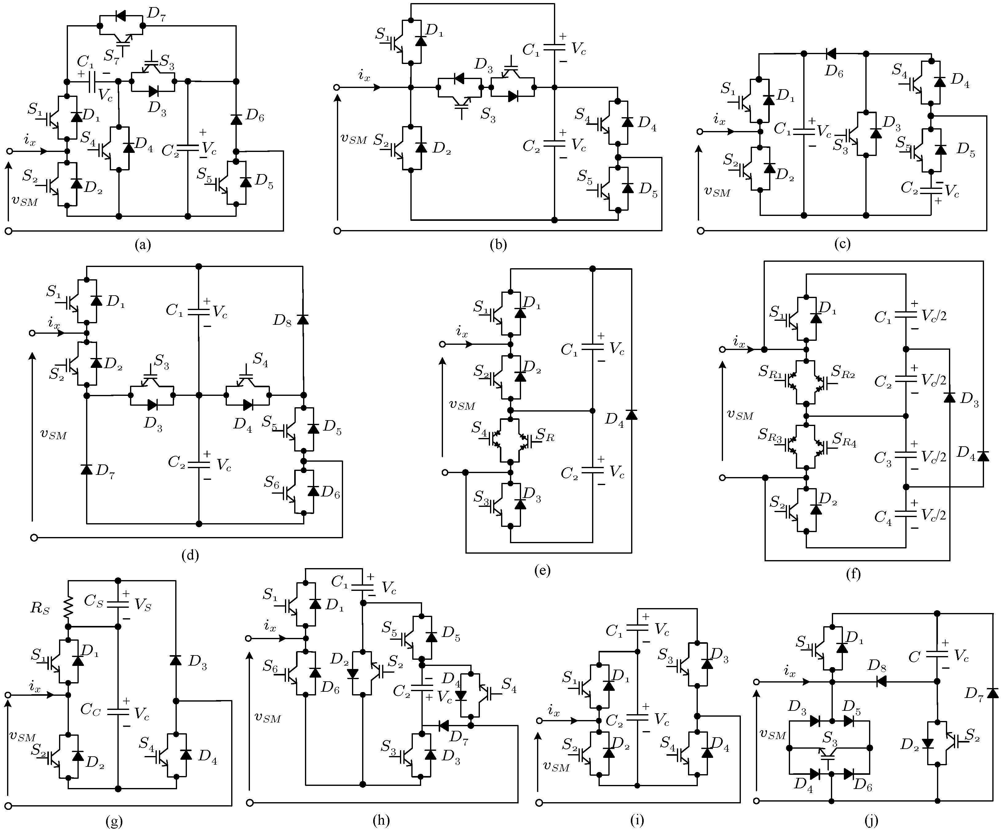
2. SM Configurations
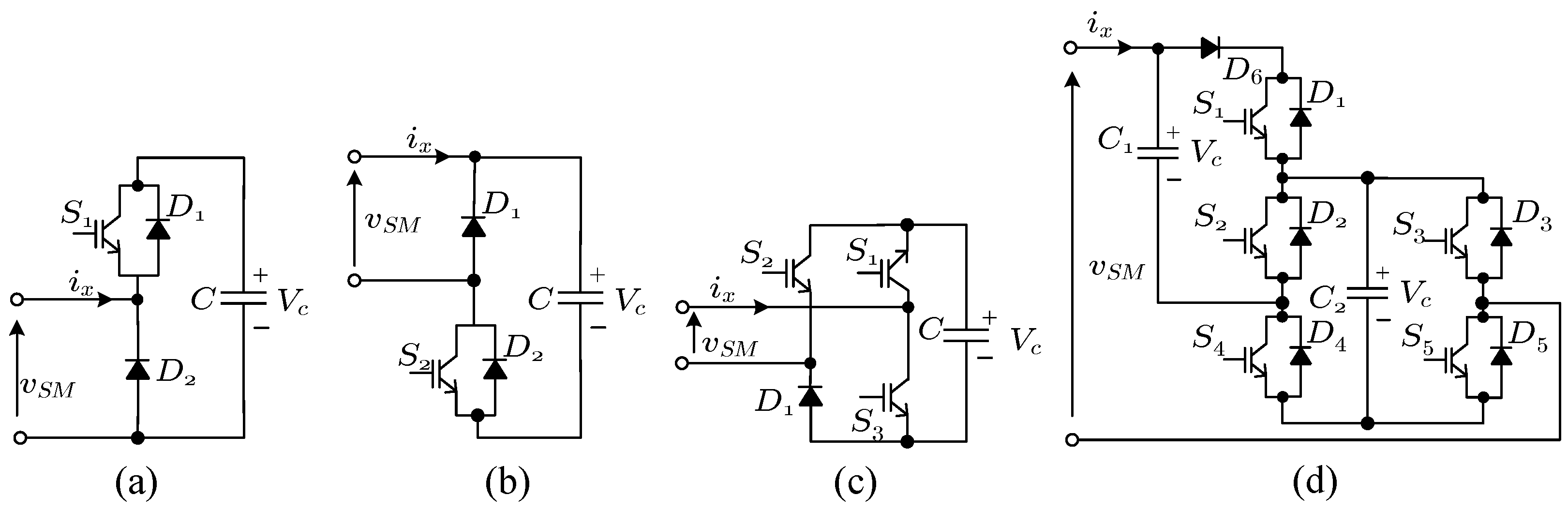
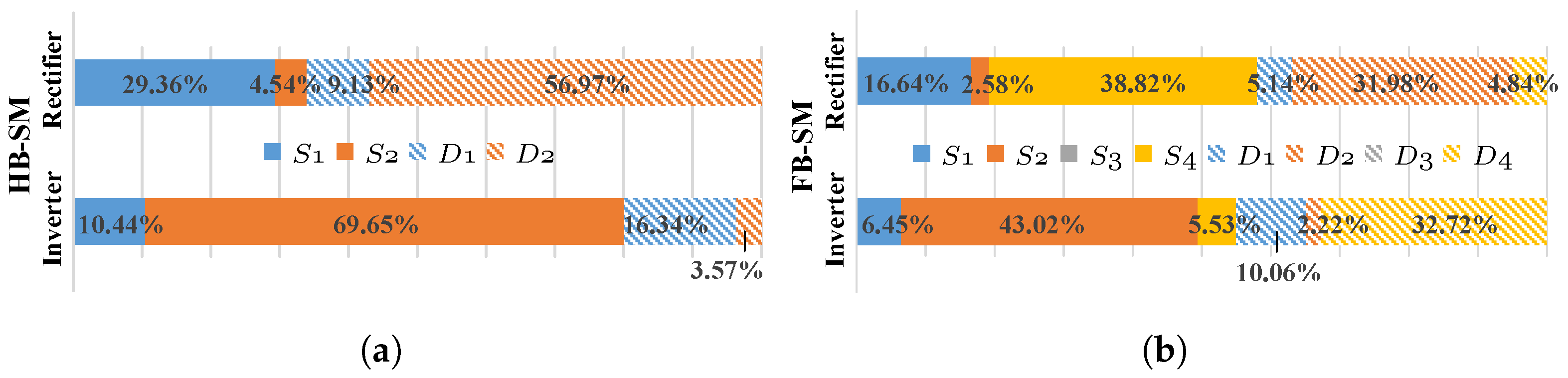
2.1. Half and Full-Bridge Sub-Modules
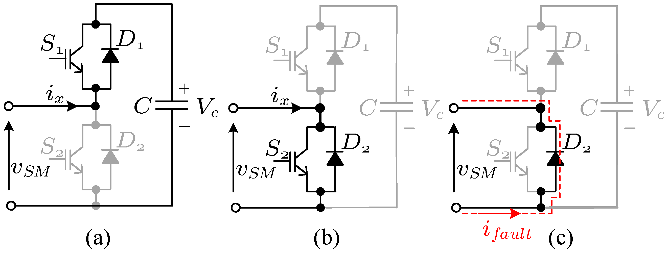
2.1.1. The Half-Bridge Submodule (HB-SM)
2.1.2. The Full-Bridge Submodule (FB-SM)
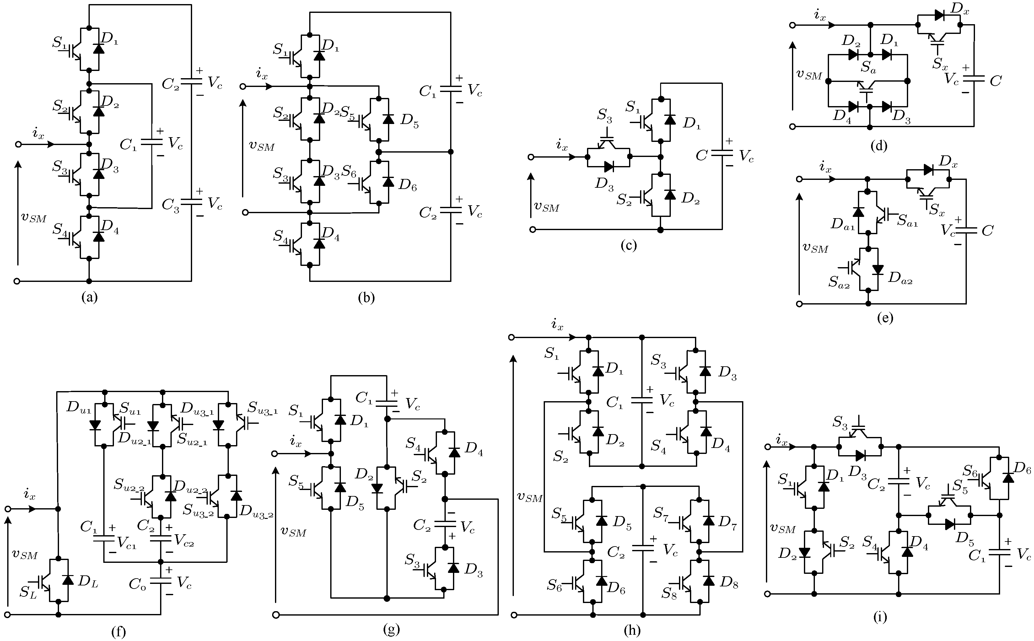
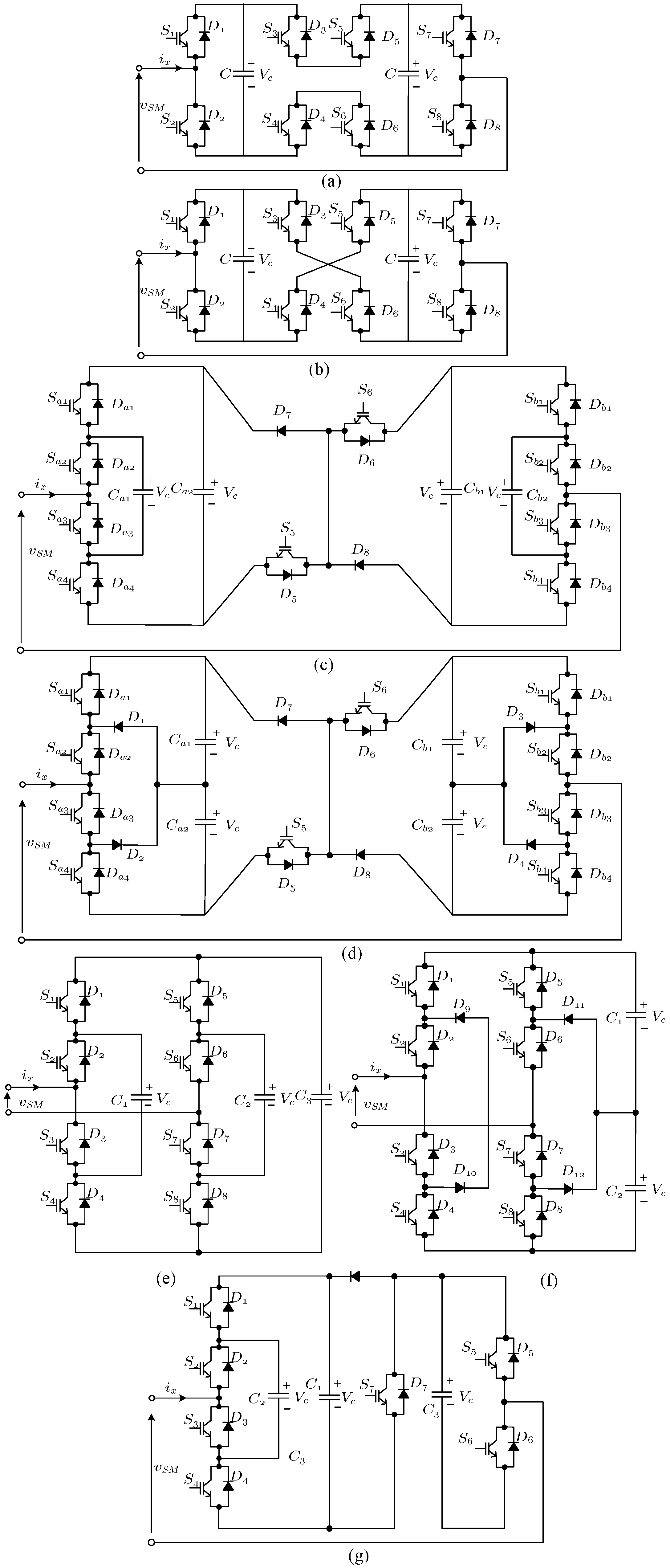
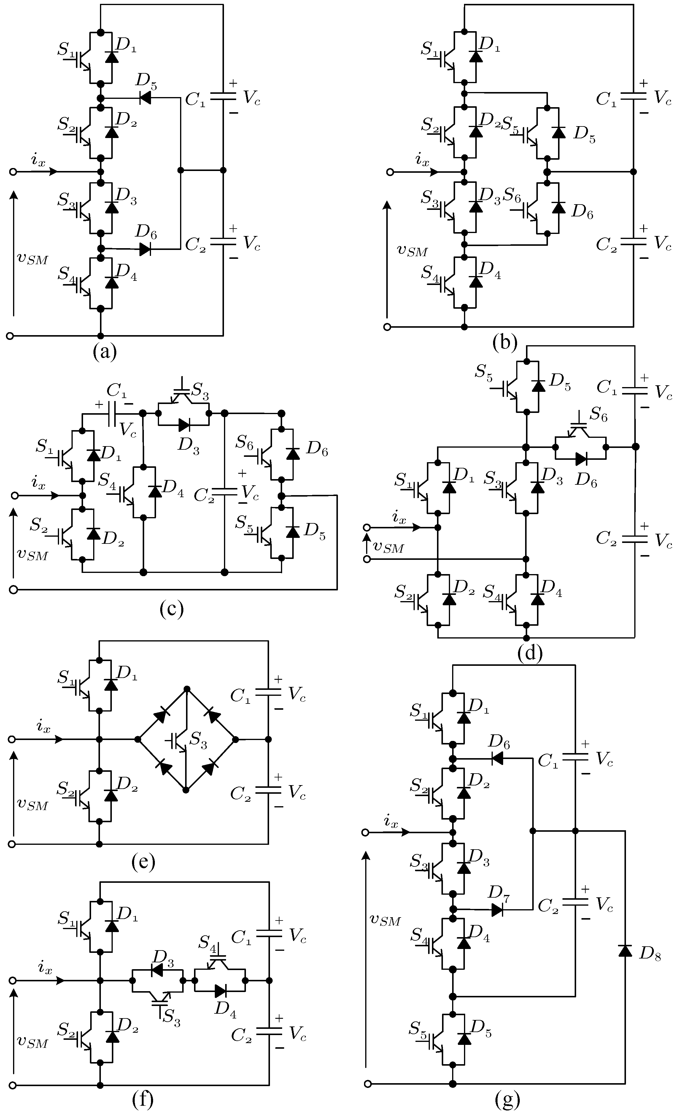
2.2. Unipolar SMs
2.3. Bipolar SMs
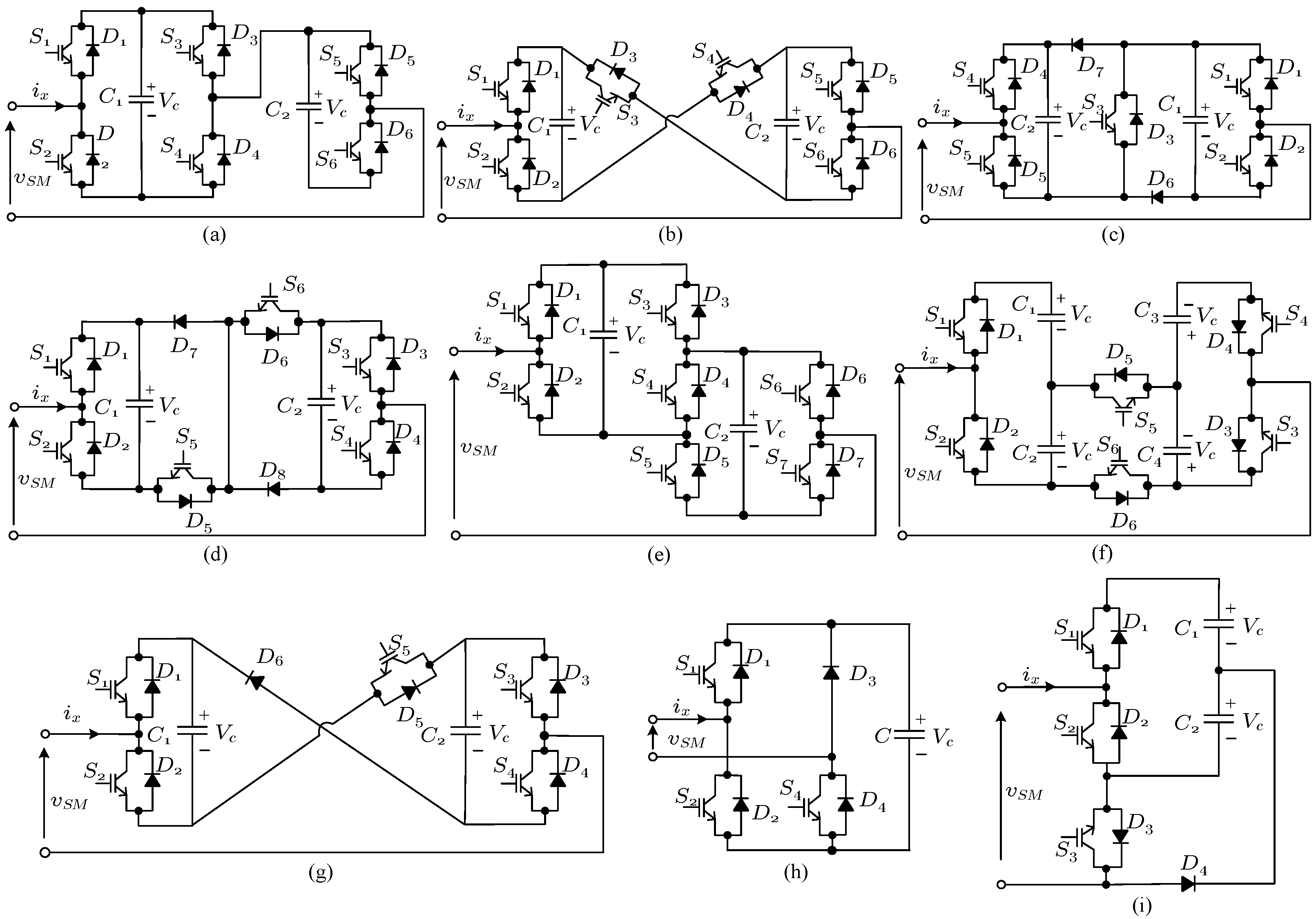
2.4. Multilevel SMs
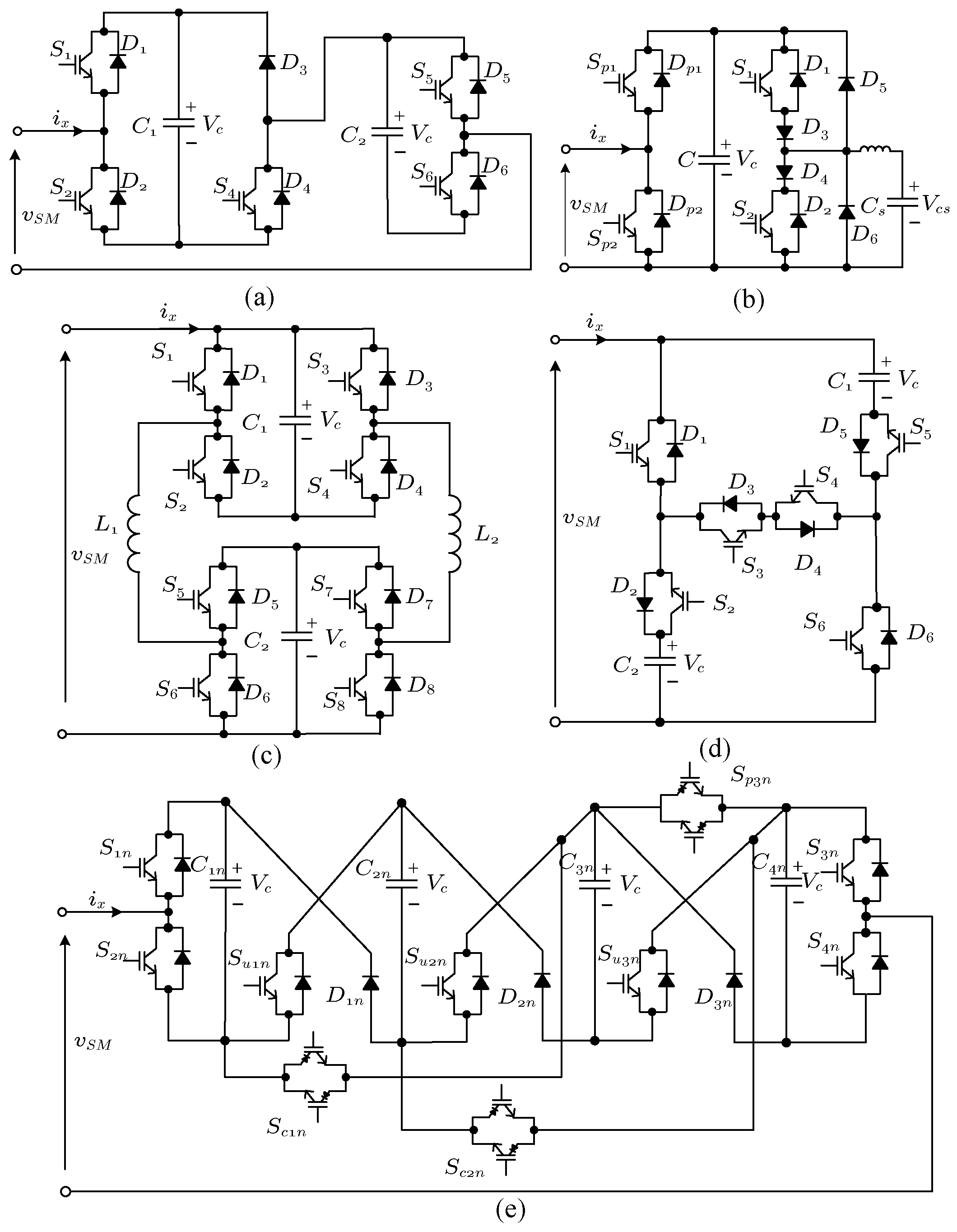
2.5. SMs with Voltage Balancing Limitations
2.6. Unidirectional SMs
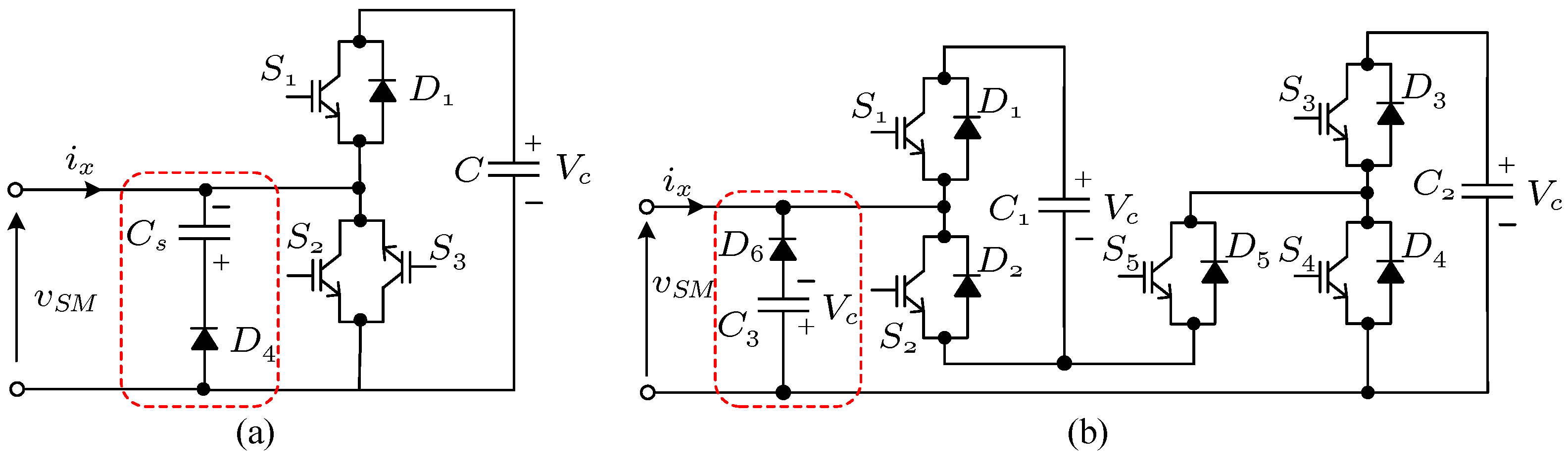
2.7. Other VSC SMs
2.8. Csc and AC-AC Submodules
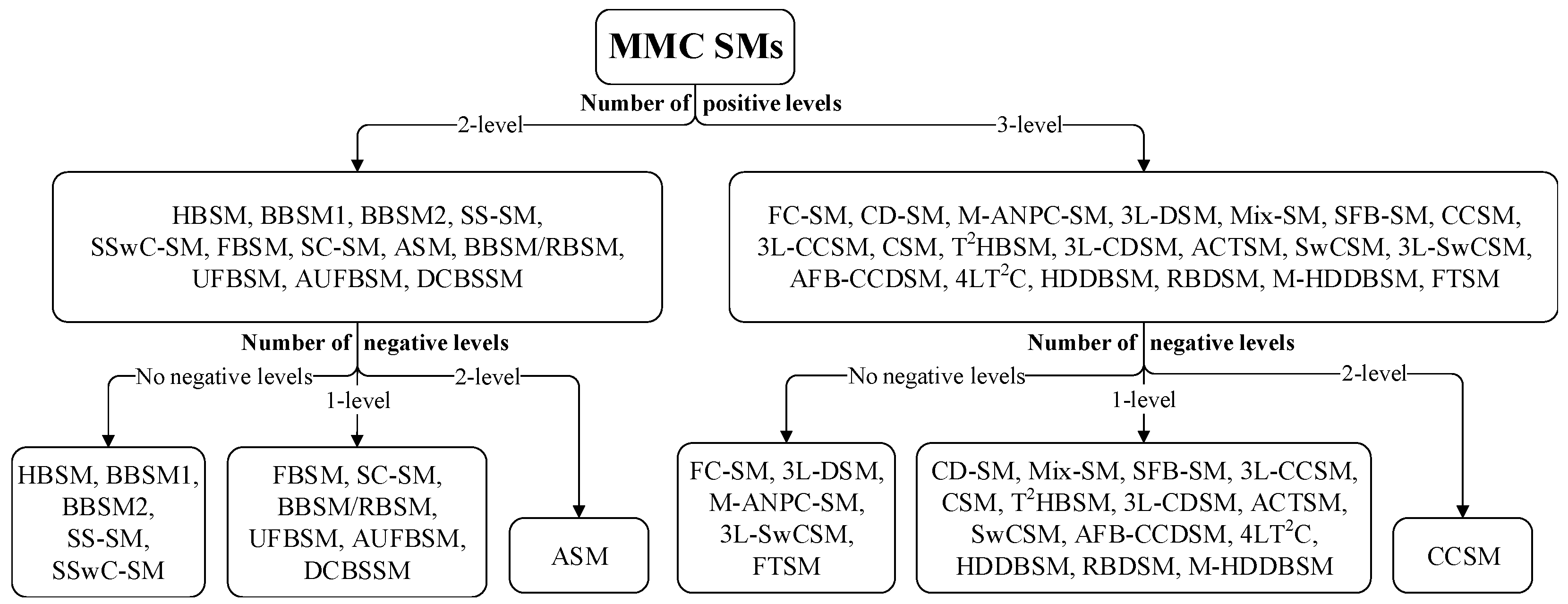
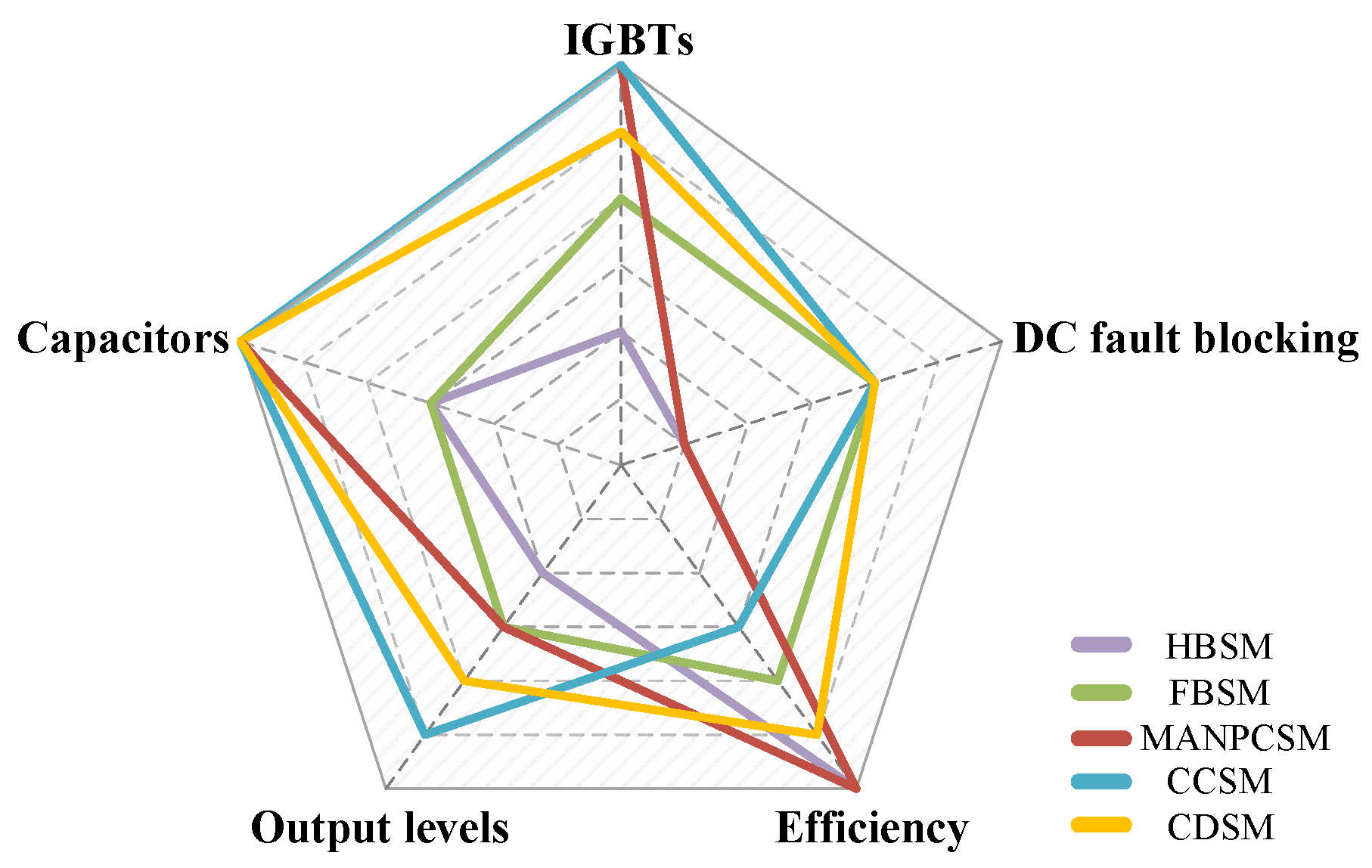
3. SMs Categorization
3.1. Output Voltage Levels
3.2. DC Fault Blocking
3.3. Negative Voltage Controllability
3.4. SM Component Count
3.5. Number of Capacitors
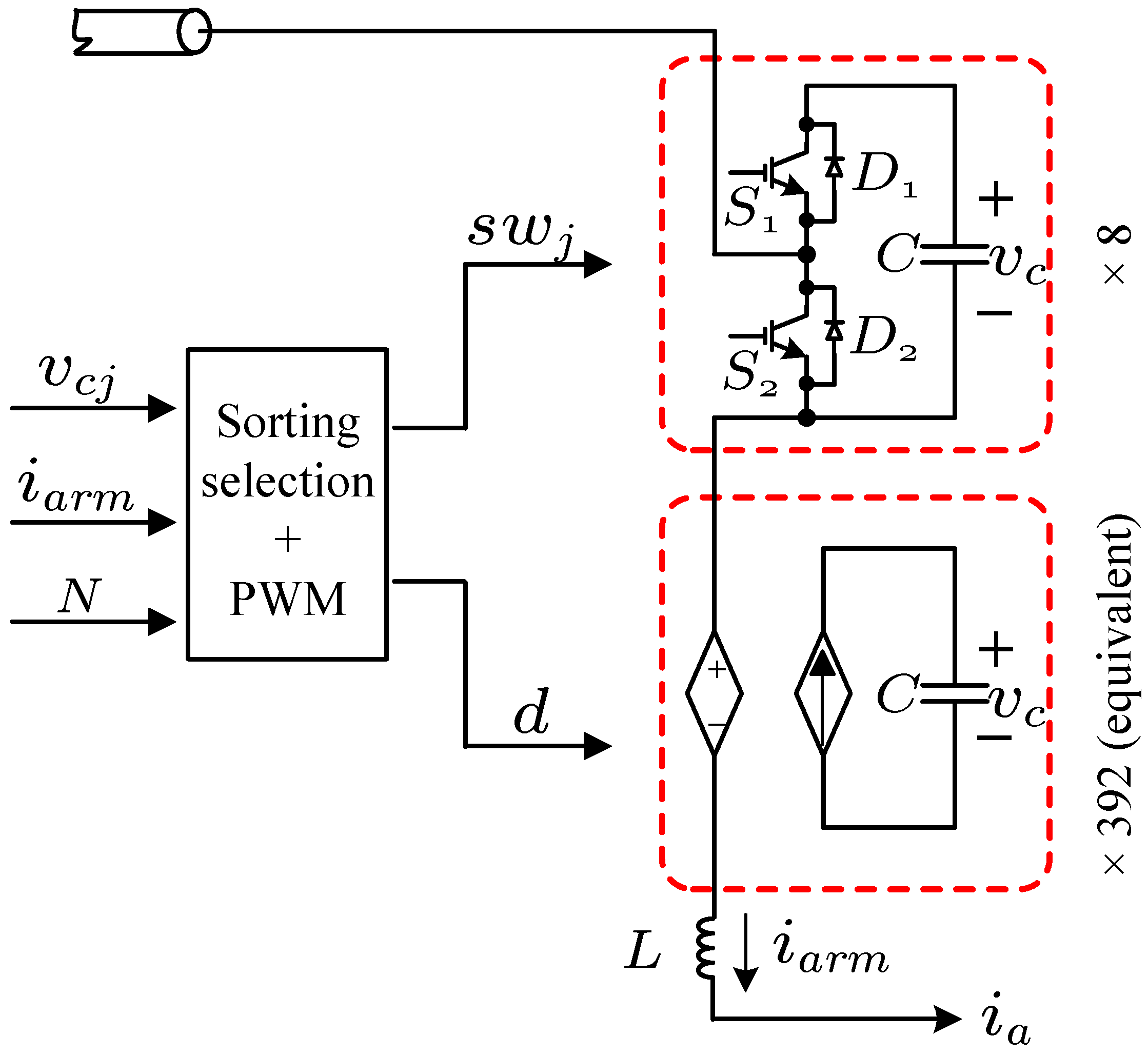
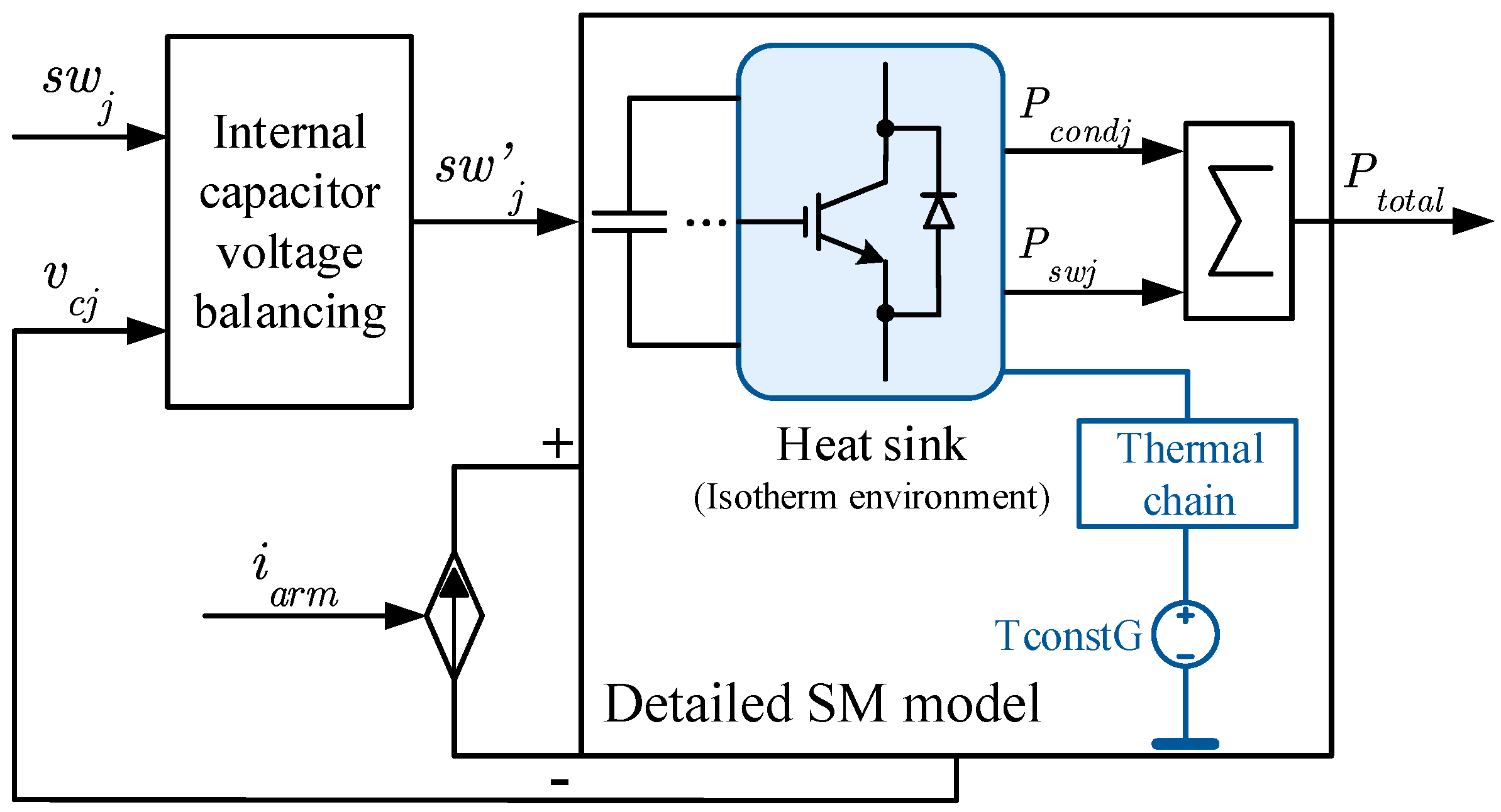
4. HVDC System Description and SM Modeling
5. Results and Comparison
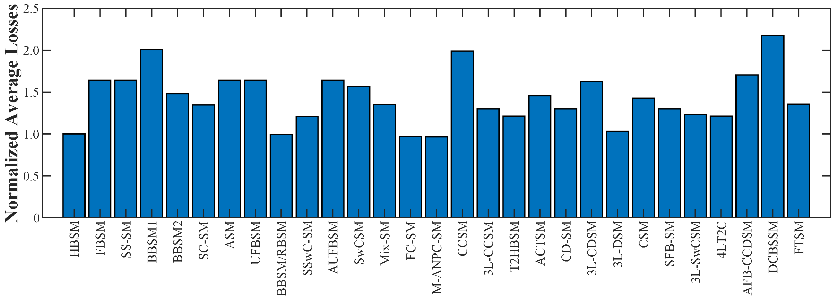
5.1. Calculation of SM Average Losses
5.2. Impact of Voltage Balancing
- The losses of one period can vary up to 20% below or above the average loss. As explained above, this results from the implementation of the SM capacitor voltage-balancing algorithm directly and is observed across all SMs;
- Certain SMs (i.e., CCSM, AFB-CCDSM) exhibit even higher variation, up to 40% as certain transitions between redundant states require multiple devices to change their switching state;
- A tighter box, which illustrates a tighter interquartile range of the losses, is more common in SMs with fewer redundant states where the variation in the losses is mostly attributed to current and timing variations;
- Multiple redundant states lead to outliers in the losses. These outliers can be above the typical maximum (e.g., AFB-CCDSM) demonstrating excessive losses for multiple periods, or below the minimum (e.g., M-ANPC-SM, FC-SM) demonstrating lower losses for certain periods. Both of these instances of outliers can impact the thermal design of the SM;
- Excessive losses without substantial benefits in the operation or functionalities of the MMC effectively limit the SMs that can be considered as feasible topologies for practical implementations.
5.3. Device Loss Distribution
6. Challenges and Future Opportunities
- Power/Voltage Ratings: Early designs of HVDC systems based on the MMC were commonly rated below 1 GW with voltage ratings around 1 kV per SM. As transmission capacity over HVDC corridors is increasing, power ratings have increased with an accompanying increase in SM voltage ratings (i.e., using 4.5 kV [85] or 6.5 kV IGBTs [86]). This design approach allows for higher dc voltages without increasing the number of SMs and the associated increase in control complexity or a reduction in the number of SMs leading to fewer dc-link capacitors, higher efficiency and improved reliability of the converter [87]. Such designs also consider compromises between fewer SMs and greater requirements of redundancy and potentially lower quality of the harmonic performance [88]. With higher rating devices, combinations of different SMs and development of hybrid MMC converters that combine two or more of the many SMs reviewed earlier [89] also become valid approaches to MMC design. Another solution to achieve even higher power capability is the parallel connection of SMs which should consider uneven current sharing and optimization of the capacitor voltage balancing capability. Such options open new directions for design of SMs, aiming towards greater MMC ratings.
- New Applications: The SM-based structure of the MMC makes it well-suited to HVDC power transmission as it elegantly addresses voltage sharing between devices connected in series and is the primary reason for the growth in MMC-based HVDC applications. With the structure and operation of the converter being better understood, its fitness to lower voltage and lower power applications can be re-evaluated. Such applications include converters for medium voltage dc (MVDC) systems for renewable and grid-connected applications [90], medium voltage motor drives, as well as transportation electrification (e.g., railway traction power supplies [14], battery chargers [91], marine vessels [92], etc.). The review and comparison we have presented in this article focuses on HVDC application to set the key requirements for the operation of the converter and SM specifications. As these new applications have different operating requirements and power/voltage design envelopes, further evaluation based on the principles introduced in this article would be required.
- DC Circuit Breakers: With the development of larger multiterminal dc systems (MTDCs) and dc grids, the design and utilization of DCCB becomes a key requirement [93]. Some of the recently proposed DCCB designs move away from the original hybrid DCCB, which was built as a combination of mechanical circuit breaker and solid-state circuit breaker [94], and towards an SM-based design which enables a reduced number of IGBTs, simpler voltage balancing and lower power losses in circuit breaker [95]. These designs can shorten the charging time of the capacitor and provide an extended period for the system to deal with faults [96]. Typical SM-based designs mostly utilise FBSMs but it has been shown that asymmetric SM structures can reduce the influence of electrical stress, reduced loop stray inductance can prevent the sharp voltage increase across IGBTs [97] or transition between current-limiting and the normal operation modes quickly [98]. Use of alternative SM configurations in DCCB applications is still limited and newer designs may further improve the operation while reducing the cost of DCCB solutions.
- DC–DC Conversion: Dc–dc converters for high-power applications are lagging in terms of development and industrial application. Modular solutions based on the MMC are a promising path forward and one where the design of SMs can have a major impact in terms of efficiency, power rating and voltage levels. A critical element in dc–dc conversion is the location of the (typically medium- or high-frequency) transformer, which can be inserted either between two converters or between each basic cells in the two sides [99]. Here, if the two sides of the dc–dc converter are connected via a single transformer, the SMs are required to withstand high current stress, which can be accomplished by high power devices. On the other hand, individual transformer is used to connect each SM to a DAB module, leading to increased system complexity and cost. Options for SM designs can consider either approach as well as one or more of the many SMs summarised in this article for developing modular dc–dc solutions suitable to different power applications.
- New Converter Designs: The introduction of the MMC has sparked new research in topologies that take advantage of modular converter structures and has led to the proposal and development of multiple new converter designs [100]. For some of these converters, common SM configurations offer optimal performance; for instance in the alternate arm converter (AAC), the presence of director switches in the arms, means that the most suitable SM in AAC is the standard FB-SM [28]. However, the fitness of the many SMs reviewed in this article to new converter designs is an open area in the current literature.
- New Semiconductor Devices: Perhaps the most important development that can lead to the development of new SM configurations for MMCs and all other modular converters and applications is the introduction of new wide band-gap semiconductor devices and specifically high-power silicon carbide (SiC) devices [101]. Compared with conventional silicon (Si) devices, SiC semiconductor devices can operate with higher operating temperature, higher switching frequency [102], higher blocking voltage, while lower switching losses [103]. Possible options in SM designs include: (i) New SMs, such as the introduction of an SiC-FET in series with the SM capacitor to limit the internal fault currents and reduce the power losses [104] due the short-circuit withstand capability of SiC MOSFETs, (ii) Hybrid SMs that combine Si with SiC devices, or (iii) optimisation of current SM configurations based on SiC devices.
7. Conclusions
Author Contributions
Funding
Institutional Review Board Statement
Informed Consent Statement
Data Availability Statement
Acknowledgments
Conflicts of Interest
Abbreviations
| d | Duty cycle |
| Current of lower arm | |
| Current of upper arm | |
| SM current | |
| Arm current | |
| Circulating current | |
| DC current | |
| Output phase currents | |
| L | Inductor |
| N | Number of SMs per arm |
| Conduction power losses | |
| Switching power losses | |
| Total power losses | |
| S | Switching device |
| Switching signal | |
| Capacitor voltage | |
| Voltage of lower arm | |
| Voltage of upper arm | |
| Arm voltage | |
| Average voltages of SM capacitor | |
| Voltages of SM capacitor | |
| DC voltage | |
| Output voltage of SM | |
| Output phase voltages | |
| SM voltage | |
| Voltage of switching device |
References
- Zhang, Y.; Ravishankar, J.; Fletcher, J.; Li, R.; Han, M. Review of modular multilevel converter based multi-terminal HVDC systems for offshore wind power transmission. Renew. Sustain. Energy Rev. 2016, 61, 572–586. [Google Scholar] [CrossRef]
- Fradley, J.; Preece, R.; Barnes, M. Assessment of the impact of MMC-VSC intrinsic energy on power system stability. J. Eng. 2019, 2019, 4012–4016. [Google Scholar] [CrossRef]
- Akagi, H. What Led to Success in Academic Research on the Family of Modular Multilevel Cascade Converters? In Proceedings of the 2018 International Power Electronics Conference (IPEC-Niigata 2018-ECCE Asia), Niigata, Japan, 20–24 May 2018; pp. 2352–2359. [Google Scholar] [CrossRef]
- Perez, M.A.; Ceballos, S.; Konstantinou, G.; Pou, J.; Aguilera, R.P. Modular Multilevel Converters: Recent Achievements and Challenges. IEEE Open J. Ind. Electron. Soc. 2021, 2, 224–239. [Google Scholar] [CrossRef]
- Martinez-Rodrigo, F.; Ramirez, D.; Rey-Boue, A.B.; De Pablo, S.; Herrero-de Lucas, L.C. Modular multilevel converters: Control and applications. Energies 2017, 10, 1709. [Google Scholar] [CrossRef] [Green Version]
- Dekka, A.; Wu, B.; Fuentes, R.L.; Perez, M.; Zargari, N.R. Evolution of Topologies, Modeling, Control Schemes, and Applications of Modular Multilevel Converters. IEEE J. Emerg. Sel. Top. Power Electron. 2017, 5, 1631–1656. [Google Scholar] [CrossRef]
- Kurtoğlu, M.; Eroğlu, F.; Arslan, A.O.; Vural, A.M. Recent contributions and future prospects of the modular multilevel converters: A comprehensive review. Int. Trans. Electr. Energy Syst. 2019, 29, e2763. [Google Scholar] [CrossRef]
- Perez, M.A.; Bernet, S.; Rodriguez, J.; Kouro, S.; Lizana, R. Circuit Topologies, Modeling, Control Schemes, and Applications of Modular Multilevel Converters. IEEE Trans. Power Electron. 2015, 30, 4–17. [Google Scholar] [CrossRef]
- Alyami, H.; Mohamed, Y. Review and development of MMC employed in VSC-HVDC systems. In Proceedings of the 2017 IEEE 30th Canadian Conference on Electrical and Computer Engineering (CCECE), Windsor, ON, Canada, 30 April–3 May 2017; pp. 1–6. [Google Scholar] [CrossRef]
- Moranchel, M.; Huerta, F.; Sanz, I.; Bueno, E.; Rodríguez, F.J. A comparison of modulation techniques for modular multilevel converters. Energies 2016, 9, 1091. [Google Scholar] [CrossRef] [Green Version]
- Akagi, H. Classification, Terminology, and Application of the Modular Multilevel Cascade Converter (MMCC). IEEE Trans. Power Electron. 2011, 26, 3119–3130. [Google Scholar] [CrossRef]
- Mohammadi, P.H.; Bina, M.T. A Transformerless Medium-Voltage STATCOM Topology Based on Extended Modular Multilevel Converters. IEEE Trans. Power Electron. 2011, 26, 1534–1545. [Google Scholar] [CrossRef]
- Wang, G.; Konstantinou, G.; Townsend, C.D.; Pou, J.; Vazquez, S.; Demetriades, G.D.; Agelidis, V.G. A Review of Power Electronics for Grid Connection of Utility-Scale Battery Energy Storage Systems. IEEE Trans. Sustain. Energy 2016, 7, 1778–1790. [Google Scholar] [CrossRef] [Green Version]
- He, X.; Peng, J.; Han, P.; Liu, Z.; Gao, S.; Wang, P. A Novel Advanced Traction Power Supply System Based on Modular Multilevel Converter. IEEE Access 2019, 7, 165018–165028. [Google Scholar] [CrossRef]
- Saeedifard, M.; Iravani, R. Dynamic Performance of a Modular Multilevel Back-to-Back HVDC System. IEEE Trans. Power Deliv. 2010, 25, 2903–2912. [Google Scholar] [CrossRef]
- Zhang, L.; Zou, Y.; Yu, J.; Qin, J.; Vittal, V.; Karady, G.G.; Shi, D.; Wang, Z. Modeling, control, and protection of modular multilevel converter-based multi-terminal HVDC systems: A review. CSEE J. Power Energy Syst. 2017, 3, 340–352. [Google Scholar] [CrossRef]
- Hahn, C.; Geuß, A.; Luther, M. Modeling and control design of hybrid - LCC and VSC based—HVDC systems. In Proceedings of the 2016 IEEE/PES Transmission and Distribution Conference and Exposition (T&D), Dallas, TX, USA, 3–5 May 2016; pp. 1–6. [Google Scholar] [CrossRef]
- Alharbi, M.; Isik, S.; Bhattacharya, S. Reliability Comparison and Evaluation of MMC Based HVDC Systems. In Proceedings of the 2018 IEEE Electronic Power Grid (eGrid), Charleston, SC, USA, 12–14 November 2018; pp. 1–5. [Google Scholar] [CrossRef]
- Marquardt, R. Modular Multilevel Converters: State of the Art and Future Progress. IEEE Power Electron. Mag. 2018, 5, 24–31. [Google Scholar] [CrossRef]
- Chen, J.; Sun, C.; Li, Y.; Xin, Y.; Li, B.; Li, G. The analysis of DC fault mode effects on MMC-HVDC system. In Proceedings of the 2017 IEEE Power Energy Society General Meeting, Chicago, IL, USA, 16–20 July 2017; pp. 1–5. [Google Scholar] [CrossRef]
- Pirhadi, A.; Bina, M.T. Design of DC-side fault current limiter for MMC-HVDC systems: Safety of the MMC along with frequency stability. IET Gener. Transm. Distrib. 2020, 14, 2419–2429. [Google Scholar] [CrossRef]
- Zhang, J.; Zhao, C. The Research of SM Topology with DC Fault Tolerance in MMC-HVDC. IEEE Trans. Power Deliv. 2015, 30, 1561–1568. [Google Scholar] [CrossRef]
- Van Hertem, D.; Leterme, W.; Chaffey, G.; Abedrabbo, M.; Wang, M.; Zerihun, F.; Barnes, M. Substations for Future HVdc Grids: Equipment and Configurations for Connection of HVdc Network Elements. IEEE Power Energy Mag. 2019, 17, 56–66. [Google Scholar] [CrossRef]
- Bösche, D.; Wilkening, E.D.; Köpf, H.; Kurrat, M. Hybrid DC Circuit Breaker Feasibility Study. IEEE Trans. Components Packag. Manuf. Technol. 2017, 7, 354–362. [Google Scholar] [CrossRef]
- Lin, W.; Jovcic, D.; Nguefeu, S.; Saad, H. Full-Bridge MMC Converter Optimal Design to HVDC Operational Requirements. IEEE Trans. Power Deliv. 2016, 31, 1342–1350. [Google Scholar] [CrossRef] [Green Version]
- Zhao, C.; Li, Y.; Konstantinou, G.; Li, Z.; Wang, P.; Lei, M.; Xu, F.; Liu, Z. Energy storage requirements of full-bridge modular multilevel converter with zero sequence voltage injection. In Proceedings of the IECON 2017—43rd Annual Conference of the IEEE Industrial Electronics Society, Beijing, China, 29 October–1 November 2017; pp. 4512–4517. [Google Scholar] [CrossRef]
- Townsend, C.; Goodwin, G.C.; Konstantinou, G.; Petranovic, N.; Mirzaeva, G.; Farivar, G.; Pou, J. Identifying Circulating Currents and Zero-Sequence Voltages for Reduction in Stored Capacitor Energy in Modular Multilevel Converters. IEEE Trans. Ind. Electron. 2020, 68, 454–465. [Google Scholar] [CrossRef]
- Wickramasinghe, H.R.; Konstantinou, G.; Pou, J. Comparison of bipolar sub-modules for the alternate arm converter. Electr. Power Syst. Res. 2017, 146, 115–123. [Google Scholar] [CrossRef] [Green Version]
- Zeng, R.; Xu, L.; Yao, L.; Williams, B.W. Design and Operation of a Hybrid Modular Multilevel Converter. IEEE Trans. Power Electron. 2015, 30, 1137–1146. [Google Scholar] [CrossRef] [Green Version]
- Elserougi, A.A.; Abdel-Khalik, A.S.; Massoud, A.M.; Ahmed, S. A New Protection Scheme for HVDC Converters Against DC-Side Faults with Current Suppression Capability. IEEE Trans. Power Deliv. 2014, 29, 1569–1577. [Google Scholar] [CrossRef]
- Solas, E.; Abad, G.; Barrena, J.A.; Aurtenetxea, S.; Cárcar, A.; Zając, L. Modular Multilevel Converter with Different Submodule Concepts—Part I: Capacitor Voltage Balancing Method. IEEE Trans. Ind. Electron. 2013, 60, 4525–4535. [Google Scholar] [CrossRef]
- Adam, G.P.; Abdelsalam, I.; Fletcher, J.E.; Burt, G.M.; Holliday, D.; Finney, S.J. New Efficient Submodule for a Modular Multilevel Converter in Multiterminal HVDC Networks. IEEE Trans. Power Electron. 2017, 32, 4258–4278. [Google Scholar] [CrossRef] [Green Version]
- Nguyen, T.H.; Lee, D. A novel submodule topology of MMC for blocking DC-fault currents in HVDC transmission systems. In Proceedings of the 2015 9th International Conference on Power Electronics and ECCE Asia (ICPE-ECCE Asia), Seoul, Korea, 1–5 June 2015; pp. 2057–2063. [Google Scholar] [CrossRef]
- Ahmed, K.H.; Adam, G.P.; Abdelsalam, I.A.; Aboushady, A.A. Modular multilevel converter with modified half-bridge submodule and arm filter for dc transmission systems with dc fault blocking capability. IET Power Electron. 2018, 11, 2253–2262. [Google Scholar] [CrossRef] [Green Version]
- Tang, Y.; Chen, M.; Ran, L. A Compact MMC Submodule Structure With Reduced Capacitor Size Using the Stacked Switched Capacitor Architecture. IEEE Trans. Power Electron. 2016, 31, 6920–6936. [Google Scholar] [CrossRef]
- Tang, Y.; Chen, M.; Ran, L. Design and control of a compact MMC submodule structure with reduced capacitor size using the stacked switched capacitor architecture. In Proceedings of the 2016 IEEE Applied Power Electronics Conference and Exposition (APEC), Long Beach, CA, USA, 20–24 March 2016; pp. 1443–1449. [Google Scholar] [CrossRef]
- Elserougi, A.; Ahmed, S.; Massoud, A. A new three-level switched-capacitor submodule for modular multilevel converters. In Proceedings of the 2016 IEEE International Conference on Industrial Technology (ICIT), Taipei, Taiwan, 14–17 March 2016; pp. 234–239. [Google Scholar] [CrossRef]
- Ilves, K.; Taffner, F.; Norrga, S.; Antonopoulos, A.; Harnefors, L.; Nee, H. A Submodule Implementation for Parallel Connection of Capacitors in Modular Multilevel Converters. IEEE Trans. Power Electron. 2015, 30, 3518–3527. [Google Scholar] [CrossRef]
- Ghazanfari, A.; Mohamed, Y.A.R.I. New Submodule Improving Fault-Tolerant Capability of Modular Multilevel Converters. IEEE Trans. Energy Convers. 2020, 35, 662–671. [Google Scholar] [CrossRef]
- Nami, A.; Liang, J.; Dijkhuizen, F.; Demetriades, G.D. Modular Multilevel Converters for HVDC Applications: Review on Converter Cells and Functionalities. IEEE Trans. Power Electron. 2015, 30, 18–36. [Google Scholar] [CrossRef]
- Marquardt, R. Modular Multilevel Converter: An universal concept for HVDC-Networks and extended DC-Bus-applications. In Proceedings of the The 2010 International Power Electronics Conference—ECCE ASIA, Sapporo, Japan, 21–24 June 2010; pp. 502–507. [Google Scholar] [CrossRef]
- Ilves, K.; Bessegato, L.; Harnefors, L.; Norrga, S.; Nee, H. Semi-full-bridge submodule for modular multilevel converters. In Proceedings of the 2015 9th International Conference on Power Electronics and ECCE Asia (ICPE-ECCE Asia), Seoul, Korea, 1–5 June 2015; pp. 1067–1074. [Google Scholar] [CrossRef]
- Huang, L.; Yang, X.; Xu, P.; Zhang, F.; Ma, X.; Liu, T.; Hao, X.; Liu, W. The evolution and variation of sub-module topologies with DC-fault current clearing capability in MMC-HVDC. In Proceedings of the 2017 IEEE 3rd International Future Energy Electronics Conference and ECCE Asia (IFEEC 2017—ECCE Asia), Kaohsiung, Taiwan, 3–7 June 2017; pp. 1938–1943. [Google Scholar] [CrossRef]
- Qin, J.; Saeedifard, M.; Rockhill, A.; Zhou, R. Hybrid Design of Modular Multilevel Converters for HVDC Systems Based on Various Submodule Circuits. IEEE Trans. Power Deliv. 2015, 30, 385–394. [Google Scholar] [CrossRef]
- Li, X.; Liu, W.; Song, Q.; Rao, H.; Xu, S. An enhanced MMC topology with DC fault ride-through capability. In Proceedings of the IECON 2013—39th Annual Conference of the IEEE Industrial Electronics Society, Vienna, Austria, 10–13 November 2013; pp. 6182–6188. [Google Scholar] [CrossRef]
- Zhang, J.; Jiang, C.; Han, Y. Modular multilevel converter composite submodule topology and control. J. Eng. 2019, 2019, 2643–2648. [Google Scholar] [CrossRef]
- Nami, A.; Adabi, J. A new T-type NPC-based submodule for modular multilevel cascaded converters. In Proceedings of the The 5th Annual International Power Electronics, Drive Systems and Technologies Conference (PEDSTC 2014), Tehran, Iran, 5–6 February 2014; pp. 137–142. [Google Scholar] [CrossRef]
- Zhao, F.; Xiao, G.; Yang, D.; Liu, M.; Han, X.; Liu, B. A novel T-type half-bridge cell for modular multilevel converter with DC fault blocking capability. In Proceedings of the 2016 IEEE Energy Conversion Congress and Exposition (ECCE), Milwaukee, WI, USA, 18–22 September 2016; pp. 1–6. [Google Scholar] [CrossRef]
- Hu, X.; Zhang, J.; Xu, S.; Jiang, Y. Investigation of a new modular multilevel converter with DC fault blocking capability. In Proceedings of the 2017 IEEE Energy Conversion Congress and Exposition (ECCE), Cincinnati, OH, USA, 1–5 October 2017; pp. 4902–4907. [Google Scholar] [CrossRef]
- Elserougi, A.A.; Massoud, A.M.; Ahmed, S. A Switched-Capacitor Submodule for Modular Multilevel HVDC Converters with DC-Fault Blocking Capability and a Reduced Number of Sensors. IEEE Trans. Power Deliv. 2016, 31, 313–322. [Google Scholar] [CrossRef]
- Kim, H.; Kang, J.; Kim, S.; Kim, C.; Hur, K. DC fault protection for modular multilevel converter HVDC using asymmetrical unipolar full-bridge submodule. In Proceedings of the 2015 9th International Conference on Power Electronics and ECCE Asia (ICPE-ECCE Asia), Seoul, Korea, 1–5 June 2015; pp. 1083–1089. [Google Scholar] [CrossRef]
- Wang, R.; Li, Z.; Wen, X.; Liu, N.; Wang, X. A Novel MMC Sub-Module Topology With DC Fault Clearance Capability. IEEE Access 2019, 7, 96085–96093. [Google Scholar] [CrossRef]
- Zhang, J.; Cui, D.; Tian, X.; Zhao, C. Hybrid double direction blocking sub-module for MMC-HVDC design and control. J. Power Electron. 2019, 19, 1486–1495. [Google Scholar] [CrossRef]
- Peng, C.; Li, R. A Low Conduction Loss Modular Multilevel Converter Topology With DC Fault Blocking Capability and Reduced Capacitance. IEEE Trans. Circuits Syst. II Express Briefs 2020, 67, 1299–1303. [Google Scholar] [CrossRef]
- Peng, C.; Li, R. A Low Conduction Loss Modular Multilevel Converter Sub-Module Topology with DC Fault blocking Capability. In Proceedings of the 2020 IEEE Applied Power Electronics Conference and Exposition (APEC), New Orleans, LA, USA, 15–19 March 2020; pp. 535–539. [Google Scholar] [CrossRef]
- Yang, X.; Xue, Y.; Chen, B.; Lin, Z.; Mu, Y.; Zheng, T.Q.; Igarshi, S. Reverse blocking sub-module based modular multilevel converter with DC fault ride-through capability. In Proceedings of the 2016 IEEE Energy Conversion Congress and Exposition (ECCE), Milwaukee, WI, USA, 18–22 September 2016; pp. 1–7. [Google Scholar] [CrossRef]
- Zhang, Z.; Jia, L.; Yang, L.; Zhang, Z.; Zhai, Z.; Wang, Y. An Improved Topology of Sub-module for MMC with DC Fault Clearing Ability. In Proceedings of the 2019 IEEE 4th International Future Energy Electronics Conference (IFEEC), Singapore, 25–28 November 2019; pp. 1–6. [Google Scholar] [CrossRef]
- Kangarlu, M.F.; Babaei, E. Cross-switched multilevel inverter: An innovative topology. IET Power Electron. 2013, 6, 642–651. [Google Scholar] [CrossRef]
- Chaudhuri, T. Cross Connected Multilevel Voltage Source Inverter Topologies for Medium Voltage Applications; Technical Report; EPFL: Ecublens, Switzerland, 2008. [Google Scholar] [CrossRef]
- Li, R.; Fletcher, J.E.; Xu, L.; Holliday, D.; Williams, B.W. A Hybrid Modular Multilevel Converter with Novel Three-Level Cells for DC Fault Blocking Capability. IEEE Trans. Power Deliv. 2015, 30, 2017–2026. [Google Scholar] [CrossRef] [Green Version]
- Efika, I.B.; Zhang, L.; Watson, A.; Clare, J. An overlapping multi-hexagon space vector modulation scheme for modular multilevel cascade converters. In Proceedings of the 2013 15th European Conference on Power Electronics and Applications (EPE), Lille, France, 3–5 September 2013; pp. 1–11. [Google Scholar] [CrossRef]
- Efika, I.B.; Nwobu, C.J.; Zhang, L. Reactive power compensation by modular multilevel flying capacitor converter-based STATCOM using PS-PWM. In Proceedings of the 7th IET International Conference on Power Electronics, Machines and Drives (PEMD 2014), Manchester, UK, 8–10 April 2014; pp. 1–6. [Google Scholar] [CrossRef]
- Solas, E.; Abad, G.; Barrena, J.A.; Aurtenetxea, S.; Cárcar, A.; Zajac, L. Modular Multilevel Converter with Different Submodule Concepts—Part II: Experimental Validation and Comparison for HVDC Application. IEEE Trans. Ind. Electron. 2013, 60, 4536–4545. [Google Scholar] [CrossRef]
- Lizana, R.; Dekka, A.; Rivera, S.; Wu, B. Modular Multilevel Converter based on 5-level submodule with DC fault blocking capability. In Proceedings of the IECON 2016—42nd Annual Conference of the IEEE Industrial Electronics Society, Florence, Italy, 24–27 October 2016; pp. 3482–3487. [Google Scholar] [CrossRef]
- Sahoo, A.K.; Otero-De-Leon, R.; Chandrasekaran, V.; Mohan, N. New 3-level submodules for a modular multilevel converter based HVDC system with advanced features. In Proceedings of the IECON 2013—39th Annual Conference of the IEEE Industrial Electronics Society, Vienna, Austria, 10–13 November 2013; pp. 6269–6274. [Google Scholar] [CrossRef]
- Chang, F.; Zhongping, Y.; Fei, L. Multilevel sub-module topology of MMC with DC fault clearance capability. High Volt. Eng. 2017, 43, 44–49. [Google Scholar]
- Mondal, G.; Nielebock, S. Reduced Switch count 5-level Modules for Modular Multi-Level Converters. In Proceedings of the IECON 2018—44th Annual Conference of the IEEE Industrial Electronics Society, Washington, DC, USA, 21–23 October 2018; pp. 1454–1459. [Google Scholar] [CrossRef]
- de Sousa, G.J.M.; Heldwein, M.L. Three-phase unidirectional modular multilevel converter. In Proceedings of the 2013 15th European Conference on Power Electronics and Applications (EPE), Lille, France, 3–5 September 2013; pp. 1–10. [Google Scholar] [CrossRef]
- Li, X.; Zhang, B.; Zhang, Z.; Qu, L.; Liao, H. A novel MMC sub-module based on controllability theory. In Proceedings of the IECON 2017—43rd Annual Conference of the IEEE Industrial Electronics Society, Beijing, China, 29 October–1 November 2017; pp. 4829–4833. [Google Scholar] [CrossRef]
- Pang, Y.; Ma, G.; Liu, X.; Xu, X.; Zhang, X. A New MMC Sub-Module Topology with DC Fault Blocking Capability and Capacitor Voltage Self-Balancing Capability. Energies 2021, 14, 3409. [Google Scholar] [CrossRef]
- Zhang, J.; Zhao, C.; Guo, L. Simulation analysis on submodule topology of modular multilevel converter. Autom. Electr. Power Syst. 2015, 39, 106–111. [Google Scholar]
- Lin, J.; Weiss, G. The virtual infinite capacitor-based active submodule for MMC. In Proceedings of the 2016 IEEE International Conference on the Science of Electrical Engineering (ICSEE), Eilat, Israel, 16–18 November 2016; pp. 1–5. [Google Scholar] [CrossRef]
- Prudhvi, M.M.; Anshuman, S. A Modular Multilevel Converter (mmc) Sub-Module Structure for Reducing Switching Losses. WO2015136552A3, 12 March 2015. [Google Scholar]
- Sallam, A.; Hamdy, R.A.R.; Moustafa, M.M.Z.; Hossam-Eldin, A. New topology for three-level modified switched capacitor submodule for Modular Multilevel Converter with DC fault blocking capability. In Proceedings of the 2017 19th European Conference on Power Electronics and Applications (EPE’17 ECCE Europe), Warsaw, Poland, 11–14 September 2017; pp. P.1–P.9. [Google Scholar] [CrossRef]
- Oliveira, R.; Yazdani, A. An Enhanced Efficiency MMC Submodule with DC-side Fault Handling Capability and Reduced Voltage Stress for HVDC Transmission Systems. In Proceedings of the 2018 IEEE Energy Conversion Congress and Exposition (ECCE), Portland, OR, USA, 23–27 September 2018; pp. 1356–1363. [Google Scholar] [CrossRef]
- Yu, X.; Wei, Y.; Jiang, Q. New submodule circuits for modular multilevel current source converters with DC fault ride through capability. In Proceedings of the 2016 IEEE Applied Power Electronics Conference and Exposition (APEC), Long Beach, CA, USA, 20–24 March 2016; pp. 1468–1474. [Google Scholar] [CrossRef]
- Sleiman, M.; Blanchette, H.F.; Al-Haddad, K.; Grégoire, L.; Kanaan, H. A new 7L-PUC multi-cells modular multilevel converter for AC-AC and AC-DC applications. In Proceedings of the 2015 IEEE International Conference on Industrial Technology (ICIT), Seville, Spain, 17–19 March 2015; pp. 2514–2519. [Google Scholar] [CrossRef]
- Li, P.; Ma, J.; Zhou, X.; Zhang, M.; Thorp, J.S. A protection scheme for DC-side fault based on a new MMC sub-module topology. Int. J. Electr. Power Energy Syst. 2020, 114, 105406. [Google Scholar] [CrossRef]
- Cwikowski, O.; Wickramasinghe, H.R.; Konstantinou, G.; Pou, J.; Barnes, M.; Shuttleworth, R. Modular Multilevel Converter DC Fault Protection. IEEE Trans. Power Deliv. 2018, 33, 291–300. [Google Scholar] [CrossRef] [Green Version]
- Li, X.; Zhao, B.; Wei, Y.; Xie, X.; Hu, Y.; Shu, D. DC fault current limiting effect of MMC submodule capacitors. Int. J. Electr. Power Energy Syst. 2020, 115, 105444. [Google Scholar] [CrossRef]
- Xu, F.; Li, Z.; Li, Y.; Wang, P.; Shi, L.; Gao, F.; Ma, X. Detailed EMT model and full-scale interface HIL test of hybrid MMC. In Proceedings of the IECON 2017—43rd Annual Conference of the IEEE Industrial Electronics Society, Beijing, China, 29 October–1 November 2017; pp. 4500–4505. [Google Scholar] [CrossRef]
- Christe, A.; Dujic, D. Virtual Submodule Concept for Fast Semi-Numerical Modular Multilevel Converter Loss Estimation. IEEE Trans. Ind. Electron. 2017, 64, 5286–5294. [Google Scholar] [CrossRef] [Green Version]
- Darus, R.; Pou, J.; Konstantinou, G.; Ceballos, S.; Picas, R.; Agelidis, V.G. A Modified Voltage Balancing Algorithm for the Modular Multilevel Converter: Evaluation for Staircase and Phase-Disposition PWM. IEEE Trans. Power Electron. 2015, 30, 4119–4127. [Google Scholar] [CrossRef] [Green Version]
- Konstantinou, G.; Zhang, J.; Ceballos, S.; Pou, J.; Agelidis, V.G. Comparison and evaluation of sub-module configurations in modular multilevel converters. In Proceedings of the 2015 IEEE 11th International Conference on Power Electronics and Drive Systems, Sydney, NSW, Australia, 9–12 June 2015; pp. 958–963. [Google Scholar] [CrossRef]
- Sanchez-Ruiz, A.; Mazuela, M.; Alvarez, S.; Abad, G.; Baraia, I. Medium Voltage—High Power Converter Topologies Comparison Procedure, for a 6.6 kV Drive Application Using 4.5 kV IGBT Modules. IEEE Trans. Ind. Electron. 2012, 59, 1462–1476. [Google Scholar] [CrossRef]
- Dujic, D.; Steinke, G.K.; Bellini, M.; Rahimo, M.; Storasta, L.; Steinke, J.K. Characterization of 6.5 kV IGBTs for High-Power Medium-Frequency Soft-Switched Applications. IEEE Trans. Power Electron. 2014, 29, 906–919. [Google Scholar] [CrossRef]
- Eckel, H.G.; Bakran, M.; Krafft, E.; Nagel, A. A new family of modular IGBT converters for traction applications. In Proceedings of the 2005 European Conference on Power Electronics and Applications, Dresden, Germany, 11–14 September 2005; pp. P.1–P.10. [Google Scholar] [CrossRef]
- Jahn, I.; Townsend, C.D.; de la Parra, H.Z. Model-predictive modulation strategy for a hybrid Si-SiC cascaded H-bridge multi-level converter. In Proceedings of the 2016 18th European Conference on Power Electronics and Applications (EPE’16 ECCE Europe), Karlsruhe, Germany, 5–9 September 2016; pp. 1–10. [Google Scholar] [CrossRef] [Green Version]
- Tian, Y.; Wickramasinghe, H.R.; Sun, P.; Li, Z.; Pou, J.; Konstantinou, G. Assessment of Low-Loss Configurations for Efficiency Improvement in Hybrid Modular Multilevel Converters. IEEE Access 2021, 9, 158155–158166. [Google Scholar] [CrossRef]
- Wang, S.; Qin, S.; Yang, P.; Sun, Y.; Zhao, B.; Yin, R.; Sun, S.; Tian, C.; Zhao, Y. Research on the New Topology and Coordinated Control Strategy of Renewable Power Generation Connected MMC-Based DC Power Grid Integration System. Symmetry 2021, 13, 1965. [Google Scholar] [CrossRef]
- Gan, C.; Sun, Q.; Wu, J.; Kong, W.; Shi, C.; Hu, Y. MMC-Based SRM Drives With Decentralized Battery Energy Storage System for Hybrid Electric Vehicles. IEEE Trans. Power Electron. 2019, 34, 2608–2621. [Google Scholar] [CrossRef]
- Tummakuri, V.; Chelliah, T.R.; Ronanki, D. Short Endurance Drive Cycle Analysis of MMC Based Absolute Battery Operated Harbor Vessel. In Proceedings of the IECON 2021—47th Annual Conference of the IEEE Industrial Electronics Society, Toronto, ON, Canada, 13–16 October 2021; pp. 1–6. [Google Scholar] [CrossRef]
- Mokhberdoran, A.; Carvalho, A.; Leite, H.; Silva, N. A review on HVDC circuit breakers. In Proceedings of the 3rd Renewable Power Generation Conference (RPG 2014), Naples, Italy, 24–25 September 2014; pp. 1–6. [Google Scholar] [CrossRef]
- Ahmed, N.; Ängquist, L.; Mahmood, S.; Antonopoulos, A.; Harnefors, L.; Norrga, S.; Nee, H.P. Efficient Modeling of an MMC-Based Multiterminal DC System Employing Hybrid HVDC Breakers. IEEE Trans. Power Deliv. 2015, 30, 1792–1801. [Google Scholar] [CrossRef]
- Jinkun, K.; Xiaoguang, W.; Bingjian, Y.; Yang, G.; Zhiyuan, H. Control strategy of the full-bridge based hybrid DC breaker. In Proceedings of the 2015 IEEE First International Conference on DC Microgrids (ICDCM), Atlanta, GA, USA, 7–10 June 2015; pp. 315–320. [Google Scholar] [CrossRef]
- Zhu, J.; Guo, X.; Yin, J.; Huo, Q.; Wei, T. Basic Topology, Modeling and Evaluation of a T-Type Hybrid DC Breaker for HVDC Grid. IEEE Trans. Power Deliv. 2021, 36, 2995–3004. [Google Scholar] [CrossRef]
- Liu, K.; Qi, L.; Dongye, Z.; Tang, G.; Cui, X. Low Inductance Design for Symmetrical Submodules in Hybrid HVDC Circuit Breaker. IEEE Trans. Power Electron. 2021, 36, 12321–12331. [Google Scholar] [CrossRef]
- Xu, J.; Feng, M.; Zhao, C. Modular Reciprocating HVDC Circuit Breaker with Current-limiting and Bi-directional Series-parallel Branch Switching Capability. J. Mod. Power Syst. Clean Energy 2020, 8, 778–786. [Google Scholar] [CrossRef]
- Jianqiao, Z.; Jianwen, Z.; Xu, C.; Jiacheng, W.; Jiajie, Z. Family of Modular Multilevel Converter (MMC) Based Solid State Transformer (SST) Topologies for Hybrid AC/DC Distribution Grid Applications. In Proceedings of the 2018 IEEE International Power Electronics and Application Conference and Exposition (PEAC), Shenzhen, China, 4–7 November 2018; pp. 1–5. [Google Scholar] [CrossRef]
- Wang, Y.; Aksoz, A.; Geury, T.; Ozturk, S.B.; Kivanc, O.C.; Hegazy, O. A Review of Modular Multilevel Converters for Stationary Applications. Appl. Sci. 2020, 10, 7719. [Google Scholar] [CrossRef]
- Rabkowski, J.; Peftitsis, D.; Nee, H.P. Silicon Carbide Power Transistors: A New Era in Power Electronics Is Initiated. IEEE Ind. Electron. Mag. 2012, 6, 17–26. [Google Scholar] [CrossRef]
- Jacobs, K.; Heinig, S.; Johannesson, D.; Norrga, S.; Nee, H.P. Comparative Evaluation of Voltage Source Converters with Silicon Carbide Semiconductor Devices for High-Voltage Direct Current Transmission. IEEE Trans. Power Electron. 2021, 36, 8887–8906. [Google Scholar] [CrossRef]
- Ericsen, T.; Raju, R.; Burgos, R.; Boroyevich, D.; Beermann-Curtin, S. Advances in SiC-based power conversion for shipboard electrical power systems. In Proceedings of the 2015 IEEE 3rd Workshop on Wide Bandgap Power Devices and Applications (WiPDA), Blacksburg, VA, USA, 2–4 November 2015; pp. 341–346. [Google Scholar] [CrossRef]
- Dahmen, C.; Marquardt, R. Progress of High Power Multilevel Converters: Combining Silicon and Silicon Carbide. In Proceedings of the PCIM Europe 2017, International Exhibition and Conference for Power Electronics, Intelligent Motion, Renewable Energy and Energy Management, Nuremberg, Germany, 16–18 May 2017; pp. 1–7. [Google Scholar]


| States | > 0 | < 0 | |||
|---|---|---|---|---|---|
| State 1 | 1 | 0 | C charging | C discharging | |
| State 2 | 0 | 1 | 0 | / | / |
| States | Number of Devices Conducting Current | ||
|---|---|---|---|
| State 1 | 0 | 1 | |
| State 2 | 0 | 1 |
| States | > 0 | < 0 | |||||
|---|---|---|---|---|---|---|---|
| State 1 | 1 | 0 | 0 | 1 | C charging | C discharging | |
| State 2 | 0 | 1 | 0 | 1 | 0 | / | / |
| State 3 | 1 | 0 | 1 | 0 | 0 | / | / |
| State 4 | 0 | 1 | 1 | 0 | C discharging | C charging | |
| State 5 | 0 | 0 | 0 | 0 | C charging | / | |
| State 6 | 0 | 0 | 0 | 0 | / | C charging |
| States | Number of Devices Conducting Current | ||||
|---|---|---|---|---|---|
| State 1 | 0 | 0 | 2 | ||
| State 2 | 0 | 0 | 2 | ||
| State 3 | 0 | 0 | 2 | ||
| State 4 | 0 | 0 | 2 | ||
| State 5 | 0 | 0 | 2 | ||
| State 6 | 0 | 0 | 2 |
| DCFB (#/#) * | Non-DCFB |
|---|---|
| FBSM (1/1) | HBSM |
| SC-SM (1/2) | FC-SM |
| CD-SM (2/2) | SS-SM |
| Mix-SM (1/2) | SSwC-SM |
| ASM (2/2) | M-ANPC-SM |
| CCSM (2/2) | 3L-DSM |
| UFBSM (1/1) | BBSM1 |
| 3L-CCSM (2/2) | BBSM2 |
| CSM (1/2) | 3L-SwCSM |
| SFB-SM (2/2) | FTSM |
| BBSM/RBSM (1/2) | |
| THBSM (1/2) | |
| ACTSM (2/2) | |
| 3L-CDSM (2/2) | |
| SwCSM (1/2) | |
| AUFBSM (1/2) | |
| AFB-CCDSM (2/4) | |
| 4LTC (1/2) | |
| DCBSSM (1/1) | |
| HDDBSM (1/2) | |
| RBDSM (1/2) | |
| M-HDDBSM (2/4) |
| Controllable (#/#) * | Non-Controllable (#/#) * |
|---|---|
| FB-SM (1/1) | SC-SM (0/1) |
| Mix-SM (1/1) | CD-SM (0/1) |
| ASM (2/2) | UFBSM (0/1) |
| CCSM (2/2) | 3L-CCSM (0/1) |
| SFB-SM (1/1) | CSM (0/1) |
| AFB-CCDSM (1/1) | BBSM/RBSM (0/1) |
| 4LTC (1/1) | THBSM (0/1) |
| ACTSM (0/1) | |
| 3L-CDSM (0/1) | |
| SwCSM (0/1) | |
| AUFBSM (0/1) | |
| DCBSSM (0/1) | |
| RBDSM (0/1) | |
| HDDBSM (0/1) | |
| M-HDDBSM (0/1) |
| Level | SM | Switch | Discrete Diode | Capacitor |
|---|---|---|---|---|
| 2-level | HBSM | 2 | 0 | 1 |
| BBSM1 | 2 | 4 | 1 | |
| BBSM2 | 3 | 0 | 1 | |
| SS-SM | 3 | 0 | 1 | |
| SSwC-SM * | 6 | 0 | 3 | |
| FB-SM | 4 | 0 | 1 | |
| ASM * | 4 | 0 | 2 | |
| SC-SM * | 3 | 1 | 2 | |
| UFBSM | 3 | 1 | 1 | |
| BBSM/RBSM | 3 | 1 | 2 | |
| AUFBSM * | 3 | 1 | 2 | |
| DCBSSM | 3 | 6 | 1 | |
| 3-level | FC-SM | 4 | 0 | 3 |
| CD-SM | 5 | 2 | 2 | |
| M-ANPC-SM | 6 | 0 | 2 | |
| 3L-DSM | 8 | 0 | 2 | |
| Mix-SM | 6 | 0 | 2 | |
| CCSM * | 6 | 0 | 2 | |
| SFB-SM | 7 | 0 | 2 | |
| CSM * | 6 | 1 | 2 | |
| 3L-CCSM * | 5 | 1 | 2 | |
| THBSM | 5 | 1 | 2 | |
| 3L-CDSM | 6 | 2 | 2 | |
| ACTSM | 6 | 2 | 2 | |
| SwCSM | 6 | 1 | 2 | |
| 3L-SwCSM | 5 | 0 | 2 | |
| AFB-CCDSM | 6 | 0 | 4 | |
| 4LTC | 6 | 0 | 2 | |
| HDDBSM | 5 | 1 | 2 | |
| RBDSM | 5 | 1 | 2 | |
| M-HDDBSM | 6 | 2 | 4 | |
| FTSM * | 6 | 0 | 2 |
| Number | SMs |
|---|---|
| 1 | HBSM, SS-SM, BBSM1, BBSM2 |
| FB-SM, UFBSM, DCBSSM | |
| 2 | M-ANPC-SM, 3L-DSM, 3L-SwCSM, |
| SC-SM, CD-SM, Mix-SM, ASM, CCSM, | |
| 3L-CCSM, CSM, SFB-SM, BBSM/RBSM, | |
| THBSM, ACTSM, 3L-CDSM, SwCSM, | |
| AUFBSM, 4LTC, HDDBSM, FTSM | |
| 3 | FC-SM, SSwC-SM, RBDSM |
| 4 | AFB-CCDSM, M-HDDBSM |
| Parameters | Value |
|---|---|
| Rated Power (MVA) | 800 |
| DC-Voltage (kV) | ±200 |
| Number of SMs per arm | 400 |
| SM Voltage (kV) | 1 |
| Stored Energy (kJ/MVA) | 30 |
| SM Capacitance (mF) | 20 |
| AC-Grid Voltage (kV) | 380 |
| Arm Inductance (p.u.) | 0.15 |
| Nominal Frequency (Hz) | 50 |
| Nominal Operating Point (p.u.) | 0.9 |
| T/F Resistance (p.u.) | 0.006 |
| T/F Leakage Inductance (p.u.) | 0.18 |
| Transformer Ratio | 0.997 |
| Short-circuit Power (GVA) | 30 |
| R/X Ratio | 0.1 |
Publisher’s Note: MDPI stays neutral with regard to jurisdictional claims in published maps and institutional affiliations. |
© 2022 by the authors. Licensee MDPI, Basel, Switzerland. This article is an open access article distributed under the terms and conditions of the Creative Commons Attribution (CC BY) license (https://creativecommons.org/licenses/by/4.0/).
Share and Cite
Tian, Y.; Wickramasinghe, H.R.; Li, Z.; Pou, J.; Konstantinou, G. Review, Classification and Loss Comparison of Modular Multilevel Converter Submodules for HVDC Applications. Energies 2022, 15, 1985. https://doi.org/10.3390/en15061985
Tian Y, Wickramasinghe HR, Li Z, Pou J, Konstantinou G. Review, Classification and Loss Comparison of Modular Multilevel Converter Submodules for HVDC Applications. Energies. 2022; 15(6):1985. https://doi.org/10.3390/en15061985
Chicago/Turabian StyleTian, Yumeng, Harith R. Wickramasinghe, Zixin Li, Josep Pou, and Georgios Konstantinou. 2022. "Review, Classification and Loss Comparison of Modular Multilevel Converter Submodules for HVDC Applications" Energies 15, no. 6: 1985. https://doi.org/10.3390/en15061985