Article

Heat Transfer Enhancement of Crossflow Air-to-Water Fin-and-Tube Heat Exchanger by Using Delta-Winglet Type Vortex Generators

Faculty of Engineering, University of Rijeka, Vukovarska 58, 51000 Rijeka, Croatia
*
Author to whom correspondence should be addressed.
Energies 2022, 15(6), 2070; https://doi.org/10.3390/en15062070
Submission received: 16 February 2022 / Revised: 8 March 2022 / Accepted: 10 March 2022 / Published: 11 March 2022
(This article belongs to the Section J: Thermal Management)

Abstract

:
The aim of this work is to numerically analyse fluid flow and heat transfer characteristics in a crossflow air-to-water fin-and-tube heat exchanger (FTHEX) by implementing two configurations of delta-winglet type vortex generators at the air side: delta-winglet upstream (DWU) and delta-winglet downstream (DWD). The vortex generators are mounted on a fin surface and deployed in a “common flow up” orientation. The effects of attack angles of 15°, 30° and 45° on air-side heat transfer and pressure drop were examined. Since the implementation of the full-size model would involve large numerical resources, the computational domain is simplified by considering a small segment in the direction of water flow. The fully developed temperature and velocity boundary conditions were set at the water inlets. To validate the defined mathematical model and numerical procedure, measurements have been performed on a plain FTHEX. The air side Reynolds number, based on hydraulic diameter, was in the range of 176 ≤ ReDh ≤ 400 and water side Reynolds number, based on inner tube diameter, was constant Redi = 17,065. The results have shown that the highest increase in the Colburn factor j (by 11–27%) and reduction in the air-side thermal resistance fraction (from 78.2–76.9% for ReDh = 176 to 76–72.4% for ReDh = 400) is achieved by using the DWD configuration with attack angle 45°. In addition, the overall heat transfer coefficient is improved by up to 15.7%. The DWD configuration with the attack angle 30° provides the greatest improvement in the heat transfer to pressure loss ratio, 5.2–15.4% over the range of ReDh studied.

1. Introduction

Compact fin-and-tube heat exchangers (FTHEX) have widespread use in commercial, domestic and industrial applications, such as heating and air conditioning systems, power plants, manufacturing processes, electronic cooling equipment and aerospace industries, etc. The FTHEXs are classified as gas-to-liquid heat exchangers, in which one fluid is a gas (more commonly, air) and the other is a low-pressure liquid (more commonly, water). For typical applications, the specific thermal resistance on the gas side accounts for a higher fraction of the total thermal resistance. Thus, the attention has been focused on enhancing the gas-side thermal performance through the development of passive and active techniques [1]. Passive techniques, unlike active techniques, do not require external energy, such as vibrations or magnetic fields, which makes them more preferable due to their ease of use and lower cost. Passive methods utilize interrupted fin surfaces and/or the insertion of vortex generators (VGs). Interrupted fins, in the form of wavy, louvered or slotted fins, improve heat transfer by disrupting primary flow with a significant pressure drop penalty. Apart from interrupting the primary flow, fins with VGs also provide better heat transfer in the recirculating zones downstream of the tubes and significantly reduce the pressure drop compared to interrupted fins [2,3].
The conventional shapes of VGs are usually in forms of delta wing, rectangular wing, delta winglet, rectangular winglet, and trapezoidal winglet (Figure 1). Wing configurations are connected to the fin surface with their trailing edges, and winglet configurations are connected with their chords. Fiebig [4] studied the performance of delta wing and winglet-type VGs for the purpose of heat transfer enhancement and reduction of flow friction. He found that the surface with delta-winglet type VGs was superior to the surface with delta-wings in terms of heat transfer performance.
The vortex generators are either punched out or mounted on the fins. Zhang et al. [5] concluded that FTHEXs with punched and mounted VGs give almost the same heat transfer and fluid flow results. Xie and Lee [6] performed three-dimensional numerical simulations of FTHEXs with punched and mounted curved-rectangular VGs. The heat exchanger performance evaluation criteria were determined by the thermal performance factor (PEC = Nu/f1/3) and the volume goodness factor (Q/VT) to evaluate the per-volume heat rejection capacity. Both factors reached the higher values for the mounted VGs.
Some authors studied the impact of winglet orientation on thermal and hydraulic performance of FTHEXs. The orientation of VGs can be divided into two configurations, “common flow up” and “common flow down”. In “common flow up” configuration the transverse gap between the leading edges of the winglet pairs is longer than that between the trailing edges. On contrary, in “common flow down” configuration the transverse gap between the leading edges of the winglet pairs is shorter that that between the trailing edges. Torii et al. [7] concluded that “common flow up” orientation causes boundary layer separation delay and reduces the pressure drop. Additionally, heat transfer was enhanced from 10% to 25% compared to “common flow down” orientation, mainly because wake zones behind the tubes were removed. Wu and Tao [8] also studied the effect of winglet orientation on heat transfer and fluid flow characteristics. Using the “common flow up” configuration the pressure drop is reduced by 8% and the Nusselt number by 3% compared to the “common flow down” configuration.
A large number of papers have investigated various geometry parameters of VGs in FTHEXs. Arrora et al. [9] selected some promising locations for maximum heat transfer enhancement, with varying attack angles between 15° and 60° for a given FTHEX with delta-winglet type VGs. Qian et al. [10] investigated the effect of attack angle, height and length by implementation of rectangular VGs. Numerical results showed that longer VG length promoted higher convective heat transfer on the air side. On the contrary, greater height did not cause better heat transfer performance. Attack angle 30° was found to produce the best heat transfer augmentation. Naik et al. [11] carried out numerical analysis for the purpose of finding the best streamwise and spanwise locations of rectangular winglet pairs. Computations were performed for FTHEXs with inline and staggered tube arrangements. Awais et al. [12] conducted numerical analysis to study the influence of attack angles, number of tube rows and different tube shapes (circular, oval and rectangular) on heat transfer performance and pressure drop on the air side of the heat exchanger with delta-winglets. Attack angle of 165° was found to provide the highest heat transfer with moderate pressure drop. Qiang et al. [13] tested different locations of VGs (before the tube, beside the tube, and behind the tube) with different attack angles in staggered tube arrangement. Authors suggested that the winglets located before and behind the tubes are the best option for the heat transfer performance. Delac et al. [14] reported that increasing the height of the rectangular winglets can lead to higher pressure drop penalty in addition to the enhanced convective heat transfer coefficient on the air side. Furthermore, a smaller winglet with a 10° attack angle produced the best heat transfer to pressure drop ratio. Sarangi and Mishra [15] carried out numerical studies on the influence of attack angle, number, streamwise and stepwise locations of rectangular winglets mounted on a fin surface. They concluded that the heat transfer increased significantly as the number and attack angle of VGs increased. Modi et al. [16] numerically studied the performance of a rectangular VG shape, with and without punched holes. Heat exchangers using VGs with punched holes showed a reduction in the flow resistance and a slight reduction in Nusselt number, compared with cases using VGs without punched holes. In recent years, several authors have experimentally and numerically studied the effect of curved VGs on the thermal-hydraulic performance of FTHEXs. Shi et al. [17] found that the configuration utilizing curved delta VGs on a fin surface achieved higher thermal-hydraulic performance compared to a plain fin configuration. The study conducted by Modi and Rathod [18] further proved that the application of the curved VGs in FTHEXs is a promising convective heat transfer enhancement technique. Xie and Lee [19] studied different parametric effects of curved rectangular VGs, including the VG height and radius. An optimal VG configuration for the thermal-hydraulic performance is identified at the VG height ratio of 0.8 and radius ratio of 1.55. In addition, the curved trapezoidal winglets were found to be a good choice for heat transfer enhancement [20,21]. However, the improved heat transfer was accompanied by an additional pressure drop penalty with respect to the case with plain fins.
In most of the available numerical studies of the FTHEXs, the tube-side fluid thermal resistance is neglected through the assumption of the constant temperature of the tube surfaces. Modelling the physical problem of fluid flow and heat transfer, using constant tube or fin surface temperature, provides good results in determining the air-side heat transfer performances when the heat capacity rate ratio C* approaches zero. However, some authors stated that in cases where C* differs from zero, the implementation of non-conjugated numerical models, in which water-side thermal resistance is neglected, could overestimate the results obtained by the measurements [10,22,23]. A few researchers have included the effect of water flow through the tubes [24,25] and showed different heat transfer characteristics, compared to a simplified non-conjugate model that only considered air-side thermal resistance.
Based on the review mentioned above, this paper investigates the influence of two delta-winglet types of VGs: upstream and downstream, on the heat transfer and pressure drop characteristics in the crossflow air-to-water fin-and-tube heat exchanger, implementing a conjugate 3D numerical model with fluid flow and heat transfer on both air and water sides. The vortex generators are attached to a fin surface and deployed in a “common flow up” orientation for the purpose of heat transfer enhancement. The effects of attack angles of 15°, 30° and 45° were investigated in order to improve air-side heat transfer performance and reduce the air-side thermal resistance fraction.

2. Mathematical Modelling

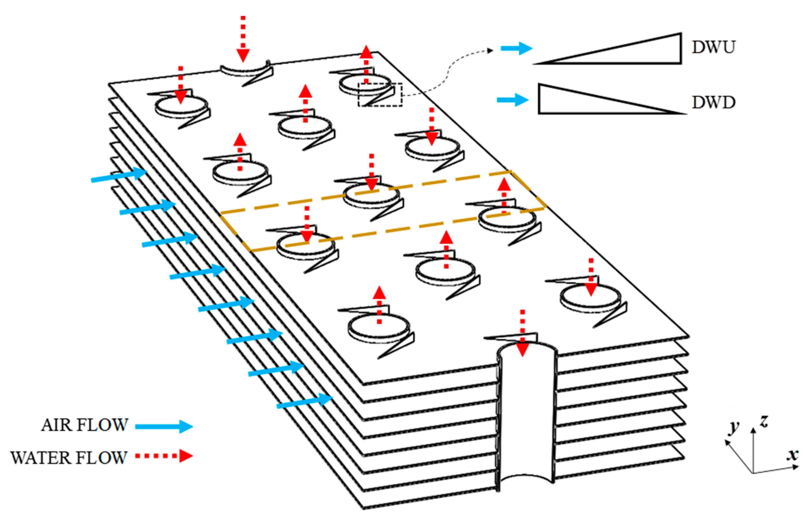
2.1. Problem Description and Computational Domain

Fluid flow and heat transfer phenomena that take place within the crossflow air-to-water FTHEX with delta-winglets has been analysed. The aluminium fins are vertically connected to the copper tubes for the purpose of air-side heat transfer increment. The fins form the channels inside where the flowing air is heated. In the present study, delta-winglet pairs are symmetrically mounted on the fin surface, adjacent to the circular tubes and deployed in “common flow up” orientation, as shown in Figure 2. In this arrangement, the air is accelerated in the constricted passages and the separation point moves downstream. By narrowing the wake and suppressing vortex shedding, poor heat transfer zones downstream of the tubes are eliminated and the pressure drop is reduced. Two delta-winglet types are investigated: delta-winglet downstream (DWD) and delta-winglet upstream (DWU), with the same height and length but different hypotenuse direction of the side profiles.
To properly describe the problem of coupled heat transfer between water and air, the total heat exchanger surface needs to be considered, since temperature changes occur in both flow directions. Since the full-size model would require large computational resources, the computational domain is simplified by considering a small segment in the direction of water flow within the heat exchanger with fully developed water inlet boundary condition. The computational domain consists of three subdomains: air, water and solid (fin, tubes and delta-winglets). Figure 3 shows the computational domain in xy-plane. The fin width is defined by half of the transverse distance between the tubes. The upper and lower boundaries of the computational domain are the central plains of two adjacent fins. Three delta-winglets have been applied to a plain fin on one side. The domain also includes air-filled space between fins. The domain boundaries are extended by the fin length in the upstream direction to ensure correct air velocity profile at the entrance. Downstream air region is extended by four fin lengths; thus, a fully developed flow pattern can be assumed at the outlet boundary.
The main dimensions of FTHEX, annotated on Figure 3 are as follows: XT = 60 mm, XL = 30 mm, Lx = 90 mm, Fp = 2.81 mm, δf = 0.2 mm, di = 14.8 mm, do = 15.9 mm. Winglet height equals 0.65 Fp (Hvg = 1.827 mm) and chord length of each winglet is 0.9 do (Lvg = 14.31 mm). The central distances between the tube and the winglet in the airflow direction and in the spanwise direction are ∆x = 0 mm and ∆y = 13 mm, respectively. In order to analyse the influence of attack angle, three attack angles (αvg) 15°, 30°, 45° were considered. A schematic view of the computational domain is presented in Figure 4.

2.2. Governing Equations

In defining a three-dimensional mathematical model, the following assumptions were made: (1) the fluid flow and heat transfer are in a steady state, (2) air and water are considered as Newtonian fluids, incompressible and without viscous dissipation, (3) fin and tubes are in ideal contact, (4) the physical properties of the fluids and solids are considered constant, since the temperature variations are relatively small, and (5) both fluid flows are considered as turbulent.
The water flow inside the tubes is an internal flow and can most commonly be considered turbulent if the tube side Reynolds number based on inner tube diameter is above 4000. In the present study, the Reynolds number value on the water side is 17,065, indicating turbulent flow. On the contrary, air flow is laminar since the Reynolds number based on the calculated hydraulic diameter ReDh does not exceed 400. Simulations of multiple streams in commercial CFD software can be performed only with the same set of governing equations, so in this investigation numerical simulations have been carried out using the Shear-Stress Transport (SST) k-ω turbulence model [26] for both air and water. Various studies of heat transfer and fluid flow in fin-and-tube heat exchangers [27,28,29,30] report that, even at low Reynolds numbers, results obtained using the SST k-ω turbulence model are in better agreement with experimental results in comparison with other available two-equations turbulence models.
Governing conservation equations, based on the abovementioned assumptions, in the following subdomains are:
Air and water subdomains
Continuity:
div ( ρ w ) = 0
Momentum (Reynolds-averaged Navier–Stokes equations):
x-velocity
div ( ρ w x w ) = p x + div ( μ grad ( w x ) ) + [ ( ρ w x 2 ¯ ) x + ( ρ w x w y ¯ ) y + ( ρ w x w z ' ¯ ) z ]
y-velocity
div ( ρ w y w ) = p y + div ( μ grad ( w y ) ) + [ ( ρ w x w y ¯ ) x + ( ρ w y 2 ¯ ) y + ( ρ w y w z ¯ ) z ]
z-velocity
div ( ρ w z w ) = p z + div ( μ grad ( w z ) ) + [ ( ρ w x w z ¯ ) x + ( ρ w y w z ¯ ) y + ( ρ w z 2 ¯ ) z ]
Energy:
div ( ρ w T ) = div ( λ c grad ( T ) ) + [ ( ρ w x T ¯ ) x + ( ρ w y T ¯ ) y + ( ρ w z T ¯ ) z ]
The Reynolds stresses in Equations (2)–(4) are computed with the Boussinesq expression:
τ i j = ρ w i w j ¯ = μ t ( W i x j + W j x i ) 2 3 ρ k δ i j
where μt is the modified turbulent viscosity and δij the Kronecker delta function. SST k-ω turbulence model combines, through blending functions, the accuracy and robustness of the standard k-ω model in the near-wall region with the freestream insensitivity of the standard k-ε model, away from the wall. The form of transport equations for turbulent kinetic energy k and specific turbulence dissipation rate ω is shown below.
The k-equation:
div ( ρ k w ) = div [ ( μ + μ t σ k )   grad ( k ) ] + G k Y k
The ω-equation:
div ( ρ ω w ) = div [ ( μ + μ t σ ω )   grad ( ω ) ] + G ω Y ω + D ω
where Gk and Gω represent the generation of k and ω, respectively. The terms denoted as Yk and Yω that appear in the above equations represent the dissipation of k and ω as a result of turbulence. The last term on the right-hand side in Equation (8) Dω is the cross-diffusion term, obtained from the transformation between the k-ω and k-ε turbulence models. A detailed description of all coefficients can be found in the literature [26,31].
Fin, tube and vortex generator subdomains
Energy:
div ( λ c grad ( T ) ) = 0

2.3. Boundary Conditions

Boundary conditions are applied at the domain’s outer boundaries and at the physical boundaries between the subdomains. The velocity and temperature profiles at the air inlet are uniform. On the contrary, in long tube circuits employed in air-to-water FTHEXs with multiple water passes, water flow is often considered as fully developed, because the entrance length is relatively short compared to the length of the water circuits. Therefore, the assumption of uniform profiles at the water inlets may be insufficient in numerical simulations. Thus, fully developed temperature and velocity profiles are set as boundary conditions at the water inlets. The outlet boundary condition, described by a fully developed fluid flow without variation of variables in the flow direction, is defined at the air and water outlets. At the front and back, as well as at the top and bottom boundary surfaces, symmetry boundary conditions have been applied. Heat transfer in the boundary layer near the wall region is used to describe heat transfer at the fluid-solid interfaces. At the fluid-solid boundaries, velocity of the fluid equals that of the solid boundary, i.e., zero, due to viscous effects. A schematic representation of the boundary conditions for FTHEX with vortex generators is given in Figure 5.

3. Numerical Method

The finite volume method [31] was used to numerically solve the defined mathematical model for the presented problem of steady fluid flow and heat transfer in crossflow FTHEX with VGs. The finite volume method is a method for solving nonlinear partial differential equations in form of algebraic equations. Other resolution methods for solving nonlinear differential equations can be found in [32,33]. The CFD software ANSYS Fluent [34] has been used for numerical calculations. The SIMPLE algorithm is used to couple velocity and pressure. The second-order upwind scheme is used to discretize the convective terms, while the central difference scheme is used for the diffusion terms. The least squares cell-based gradient method was used to evaluate the values of a scalar at the cell faces, secondary diffusion terms and velocity derivatives. The iteration process stops when the convergence criteria are achieved. The convergence criteria were 10−6 for continuity and momentum equations, 10−5 for turbulence kinetic energy and turbulent frequency equations and 10−9 for the energy equation. The simulations were carried out on PC, based on two Intel Xeon processors, with 8 cores each.
Water inlet velocity and temperature profiles, necessary to implement fully developed boundary condition, were obtained using a custom procedure based on that of Fan et al. [35]. Numerical calculation with uniform profiles of water inlet velocity and inlet temperatures was initially performed. When the numerical solution is converged, the newly obtained water velocity and temperature profiles at the outlet boundary are assigned to the inlet boundary conditions for the next numerical calculation. In order to establish the defined water inlet temperature, each temperature profile was corrected with a distinctive temperature drop achieved through the water segment. The simulations were then carried out again using the new inlet profiles. After a certain number of computations implementing this approach, fully developed velocity profiles are obtained. Several termination criteria were defined to ensure fully developed water flow:
  • Change in standard deviation of velocity profiles between inlet and outlet water boundaries is less than 0.1%;
  • Change in minimum and maximum velocity values between inlet and outlet water boundaries is less than 0.1%;
  • Change in air outlet temperature between two separate simulations is less than 0.002 °C.
The temperature profiles were updated using a self-written user-defined function (UDF), written in C code and implemented in Fluent solver. The time required for one simulation to converge was nearly 20 min, and the fully developed boundary condition was reached after about 90 simulations, i.e., 30 h.
The computational domain was discretized with a hexahedral mesh created using the ANSYS Workbench meshing tool. A fine mesh was generated around tubes, fins and delta-winglets to take into account high velocity and temperature gradients. In order to improve the quality and sensitivity of the mesh, multi-block grid approach has been applied. Computational domain has been divided into 4000 individual blocks. Structured mesh was generated in all zones, except VG zones, where unstructured hexahedral cells were defined. The mounted VGs were treated as solid steps and meshed using the stepwise approximation method, similar to Refs. [36,37,38,39]. As reported by Mangrulkar et.al. [40], the near-wall grid points should be placed in the viscous sublayer (y+ ≤ 1). In the current study, careful attention was paid to maintain a dense mesh near the solid surfaces, resulting in an average wall y-plus (y+) value of 0.23–0.38. The quality of generated mesh was checked based on cell skewness. The average value of the skewness was 0.08 and maximum value was 0.6. The schematics of the mesh system are presented in Figure 6.
The mesh independence test was carried out for the case of the FTHEX with DWD configuration and the attack angle αvg = 30° with five different sizes of the mesh: 0.6 million, 1.12 million, 1.61 million, 2.11 million and 2.59 million cells. Computed values of air outlet temperatures and air-side pressure drops for selected test conditions are shown in Figure 7, showing no significant difference in results after the third mesh refinement. To achieve reasonable accuracy with shorter computation time, all simulations were performed with the mesh size of 1.61 million cells. Mesh generation and the independence test were performed using the same approach for the air-to-water FTHEX with plain fins, and a similarly sized mesh has been adopted.

4. Experimental Validation

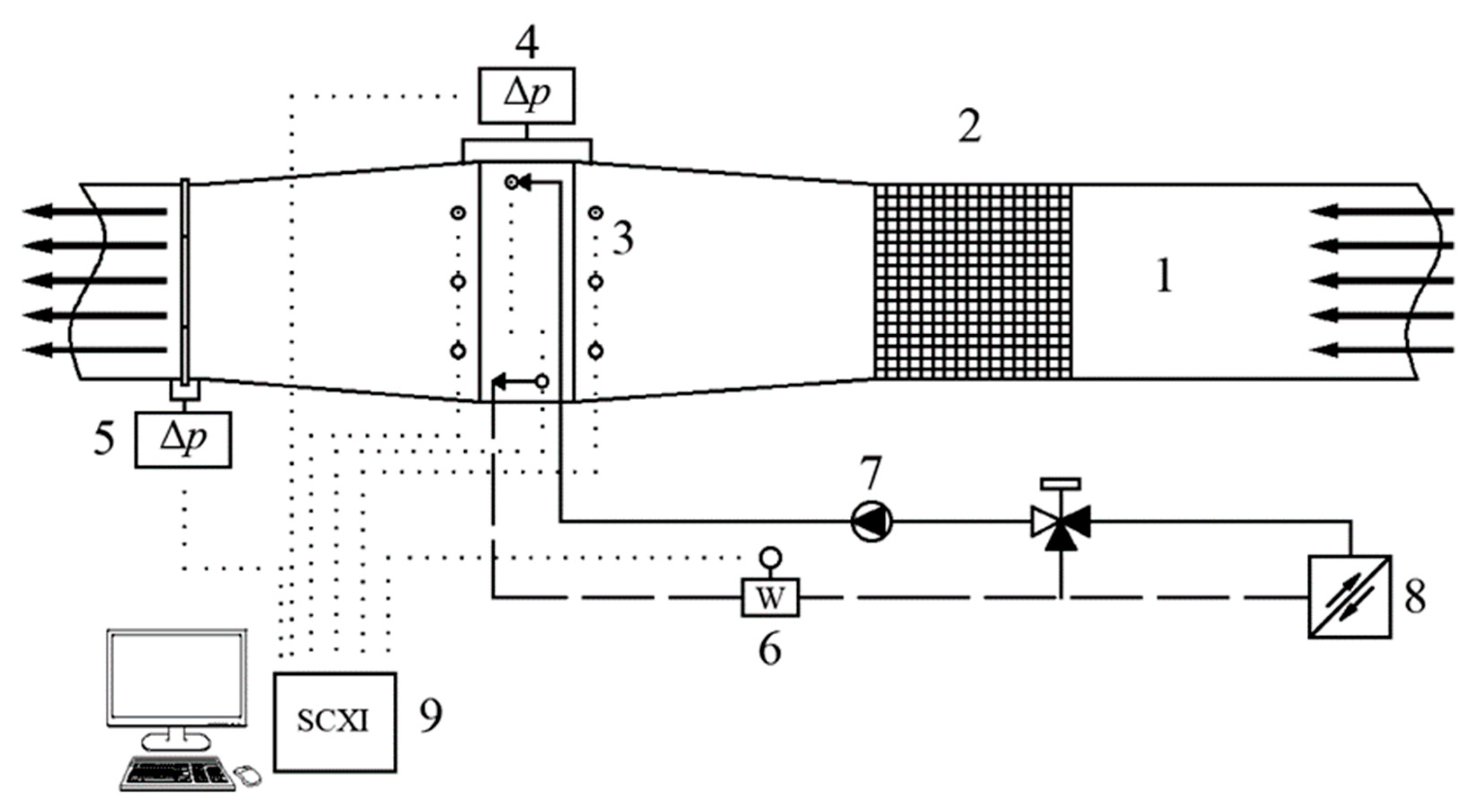
4.1. Experimentally Studied Fin-and-Tube Heat Exchanger and Test Line

Experiments on air-to-water plain FTHEX, installed in an open circuit wind tunnel, were performed in the Laboratory for Thermal Measurements at the University of Rijeka, Faculty of Engineering. The internal dimensions of the FTHEX are 90 mm, 730 mm and 780 mm for length, depth and width, respectively. The analysed heat exchanger contains 260 plain aluminium fins with a fin pitch of 2.81 mm and thickness of 0.2 mm, and a total of 38 staggered-arranged copper tubes, arranged longitudinally in three rows and transversally in thirteen rows. The tube internal diameter is 14.8 mm, and the outside diameter equals 15.9 mm. On the tube side, water is distributed among seven Z-shaped flow circuits with different design and numbers of passages. Five water circuits have six-pass arrangement and two of them have four-pass arrangement. The distance between centre of the tubes was determined with the longitudinal and transverse tube pitches of 30 mm and 60 mm, respectively. The test line consisted of an open wind tunnel and a closed water loop. The heat exchanger test section was equipped with temperature, velocity and pressure drop measurement sensors and a data acquisition system. The segment of the test line is shown in Figure 8. The FTHEX was placed inside the test section, downstream of a flow straightener that minimizes the effects of air maldistribution and provides the uniform velocity distribution at the FTHEX inlet. A 3.5 kW blower placed inside the air handling unit delivered air to the test section. Air mass flow rate was determined with a differential pressure sensor attached to a calibrated orifice plate, and water-side mass flow rate was measured using an ultrasonic mass flow meter. The air-side pressure drop across FTHEX was measured using differential pressure sensors. The inlet air velocities were measured with four hot-wire anemometers.
Air inlet and outlet temperatures were measured with thermocouple arrays placed upstream and downstream of the FTHEX, consisting of five and fifteen K type thermocouples, respectively. Water temperatures at the heat exchanger inlet and outlet headers were measured using four Class “A” platinum resistance thermometers, two at the inlet and two at the outlet. All the measurement signals are collected and converted by the National Instruments SCXI data acquisition system, where measurement data was stored every 1 s through LabView software [41], installed on a personal computer. The FTHEX test section and closed water loop are shown in Figure 9.
The accuracy of the hotwire anemometers is ±0.015 m/s or ±2%, whichever is greater. The accuracy of K-type thermocouples is ±0.3 °C, within the measuring range from 20 °C to 40 °C (after calibration) and the uncertainty of the Class “A” platinum resistance sensors is ±0.15 °C (in accordance with DIN IEC 751 standard). The accuracy of both the differential pressure sensor for airflow rate measurements and the ultrasonic water mass flow meter is ±2%. Average heat balance dispersion for each of the measurements was less than 5%.

4.2. Test Conditions

The experimental investigations were performed for different airside working conditions. The air mass flow rate varied from 1225 to 2770 kg/h, with corresponding frontal air velocities from 0.46 to 1.03 m/s. The air-side Reynolds number based on hydraulic diameter ranged from 176 to 400. During the measurements, the air inlet temperature and water inlet temperature were constant at 22 °C and 40 °C, respectively. The water mass flow rate was 3260 kg/h, with corresponding Reynolds number 17,065. The range of heat capacity rate ratio C* = Cair/Cwater was between 0.09 and 0.21.

4.3. Model Validation

A comparison between experimental and numerical results for the baseline air-to-water FTHEX with plain fins is presented in Figure 10. The results comprise values of average air outlet temperatures Tair,out and air-side pressure drops ∆pair. The comparison between numerical predictions and experimental data shows good agreement of the analysed variables. The temperature difference between experimental and numerical results are within 0.26 °C for a given range of air inlet velocities and specified test conditions. The numerical results for the air-side pressure drop coincide well with the measured data and the deviations are within an acceptable range. These agreements between the numerically predicted and experimentally obtained results on air-to-water FTHEX with plain fins demonstrate the reliability of the defined mathematical model, with non-uniform velocity and temperature profiles at the water inlets, and numerical procedure. Although the flow straightener was installed prior to the test section to ensure the air uniformity, there is still some small degree of non-uniformity. Since the velocity distribution at the air inlet was treated as perfectly uniform in the numerical simulations, this may be the cause of slight discrepancies between the numerical results and the measurements, with respect to the air-side pressure drop.

5. Results and Discussion

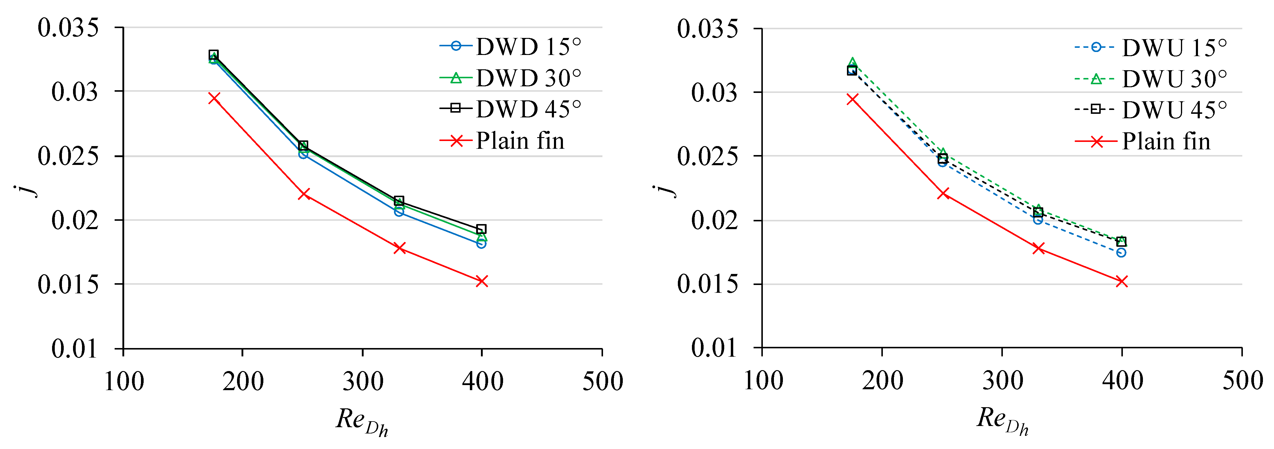
5.1. Comparison of Air-Side Colburn Factors j and Friction Factors f

In order to investigate the effects of the attack angle on the air-side thermal and hydraulic performances of FTHEX with delta-winglets, three different angle values were considered: 15°, 30°, and 45°. The air-side heat transfer characteristics are presented in terms of the dimensionless convective heat transfer factor, i.e., the Colburn j factor:
j = h o ρ w core c p Pr 2 / 3
where wcore is the average velocity in the minimal flow cross-sectional area. The air-side convective heat transfer coefficient ho is obtained by subtracting the water-side thermal resistance and the wall thermal resistance from the overall thermal resistance:
h o = 1 η o ( 1 U ln ( d o / d i ) A o 2 π λ wall L z N t A o h i A i ) 1
where U is the overall heat transfer coefficient, λwall is thermal conductivity of the wall material, Lz is the tube length, Nt is the number of tubes, and hi is the water-side heat transfer coefficient, determined numerically with the following equation:
h i = Q ˙ water A i ( T b T wall )
where Tb is the bulk temperature of the water flow and Twall is the average temperature of inner tube wall. In Equation (11), the overall surface efficiency ηo is calculated from the fin efficiency ηf using the equation:
η o = 1 A f A o ( 1 η f )
The fin efficiency ηf is calculated using the iterative Schmidt approximation method [42], adopted by many authors [43,44,45,46] in the study of FTHEXs.
Figure 11 shows the effect of the attack angle on the values of Colburn factor j for configurations with delta-winglet downstream (DWD) and delta-winglet upstream (DWU) VGs, in a given range of air-side Reynolds numbers. The numerical results for plain FTHEX are presented as a baseline case. It can be seen that the Colburn factor j decreases with increasing Reynolds number for baseline case and the cases with delta-winglets. Although the mixing of the air improves at higher Reynolds numbers for all cases, the j-factor decreases because it is commonly inversely proportional to the Reynolds number [1]. The comparison of the numerical results shows that when fins with delta-winglets are used, a higher j-factor is achieved at the same Reynolds number, which can be explained by the fact that the delta winglets generate the secondary flow, and the air can impinge directly on the fin surface. However, the heat exchanger with DWD winglets exhibits slightly better heat transfer performance for each of the attack angles studied. In the case with DWD winglets, the j-factor increases with increasing angle of attack. For the DWU configuration, the j-factor is highest at the attack angle of 30°. Compared to the plain FTHEX, the j-factor improved the most for the DWD case with αvg = 45°, by 11–27% over the range of the air-side Reynolds number considered. The FTHEX with DWU configuration and αvg = 30° improved the air-side j-factor by 9.5–21%.
The increase in heat transfer is often accompanied by an additional pressure drop. Figure 12 shows the relations between the friction factor f and the Reynolds number on the air side at different attack angles. It can be observed that the air-side friction factor f decreases with increasing Reynolds number for all FTHEXs considered. As the angle of attack increases, the larger projected area of the winglet normal to the incoming air flow causes the magnitude of the drag and friction factor to increase as well. Both the DWD and DWU arrangements yield the highest friction factor at an attack angle of 45°. In the present study, friction factors for αvg = 15°, 30°, 45° are increased by 11–15.6%, 18.5–25.8%, and 21.7–38.7%, respectively, for the DWD configuration and by 7.5–9.4%, 12.2–17.7%, and 19.4–32.4%, respectively, for the DWU configuration over the ReDh range (176–400) compared to the baseline case.

5.2. Distributions of Temperatures, Velocities and Air-Side Heat Transfer Coefficients

The plots of the velocity vectors and temperature fields provide information about the air-side heat transfer and pressure drop characteristics in the FTHEX. The velocity and temperature distributions are shown in Figure 13 and Figure 14 for plain air-to-water FTHEX and FTHEXs with two differently oriented delta-winglets, along the central airflow surface (z = 1.405 mm) and the air inlet velocity wair,in = 1.03 m/s (ReDh = 400). From the velocity distributions in Figure 13, it can be seen that wake vortices are relatively large behind the circular tubes for the heat exchanger with plain fins. Furthermore, strong recirculation occurs which results in poor heat transfer performance in this region. Wake vortices belong to transverse vortices and are generated due to the detachment of a boundary layer on the tube surface. However, for the heat exchangers with delta-winglets the wake regions diminish, especially with the increase in the attack angle. The low velocity zones in the rear of the tubes are washed away by the high-momentum air passing through the nozzle-like passages between the tubes and winglets, and the flow separation is delayed. Furthermore, as the attack angle increases, zones of low air velocities become visible behind the VGs in a given plane due to the greater influence of the induced normal velocities of the vortices. The observed size of the recirculation zone is almost the same for the first and second tube rows, while it is larger for the third tube row. For the plain fin configuration, the high-temperature air is trapped in the wake region after heat exchange with the tube wall, which is clearly evident from the temperature distribution in Figure 14. The phenomenon of the air being trapped in the recirculation zone leads to deterioration of the heat transfer at the rear part of the tube, which in turn leads to an excessively high local temperature in this area. The heat transfer performance in the wake regions is improved by the addition of delta-winglets and the air temperature decreases rapidly. At the same time, the air flowing over the winglets causes an increase in local disturbances and destruction of the thermal boundary layer. The air temperature in the outlet region of FTHEX is higher, indicating better air-side heat transfer performance of the fins with delta-winglets. As shown in Figure 14, the DWD and DWU winglets with attack angle of αvg = 45° mainly resulted in lower temperatures of the wake regions compared to the other cases, with the exception of the third tube row for the DWD case, indicating enhanced fluid mixing and heat transfer improvement from the fins and tubes to the air. The augmented temperature gradient in the rear part of the tubes corresponds to an increased exchange of heat fluxes and local heat transfer coefficients for the wake zones.
In order to examine the air-side heat transfer behaviour along the airflow direction, the local distributions of the air-side heat transfer coefficient (HTC) on the fin surfaces with and without VGs for wair,in = 1.03 m/s (ReDh = 400) are shown in Figure 15 and Figure 16. The surface with the VGs is the lower fin surface and the surface without VGs is the adjacent upper fin surface. The local regions of high heat transfer associated with the (I) horseshoe vortices formed at the tube surface, (II) the longitudinal main and corner vortices formed in the presence of delta-winglets and (III) guidance of the airflow in the wake zones visible on the air-side HTC contours. It is evident that the maximum values of the air-side HTC on both fin surfaces occur at the entrance of FTHEX and then gradually decrease toward the airflow direction due to the development of the thermal boundary layer. The longitudinal vortices generated by the fins with delta-winglets drastically improve the heat transfer in different local regions. The zones of low heat transfer behind the tubes are narrowed due to the reduction in recirculated wakes. A larger attack angle of delta-winglets diverts more air particles toward the wake zones, resulting in smaller recirculation patches. The formation of the vortex structure also reveals higher HTC zones near the upper lateral edges of the winglets on the surface with VGs and in the zones of the leading (DWD configuration) or trailing (DWU configuration) edges of the winglets on the surface without VGs. These zones intensify at larger attack angles, due to the more intense secondary flow.
The HTC is more enhanced in the wake region of the fins with the DWU configuration of VGs, owing to the increased winglet area towards the rear of the tubes. However, for the cases with the DWD configuration the enhanced air-side HTC zones are spread out towards the outlet boundary and the HTC field is evenly distributed in the spanwise direction, which is due to better mixing and higher intensity of the vortex flow, as shown from the air streamlines in Figure 17. The longitudinal vortices interact with the boundary layer, creating a swirling flow that mixes the near-wall air with the free-stream air. From the above cross-sections, it can be seen that both delta-winglet configurations produce a rotating and secondary flow that leads to mixing of the air, disruption of the boundary layer, and thus better convective heat transfer between air and fin surfaces. The vortices with the largest extension are called the main vortices and they contribute most to the improvement of heat transfer along the flow channel. The intensity of the longitudinal vortices from the first row of VGs (x = 15 mm) is lower than that of the second row (x = 45 mm). From the overall observations of the flow patterns, it can be concluded that the transport of air is better for the DWD configuration.

5.3. Comparison of the Air-Side Thermal-Hydraulic Performances

From the previous discussion, it can be concluded that the presence of delta-winglets increases the heat transfer of the heat exchanger with the considerable pressure drop on the air side. A measure of performance, accounting for both heat transfer and pressure loss for equal pumping power on the air side of FTHEX with delta-winglets, is determined by the thermal performance factor TPF [47] defined as:
T P F = j / j ref ( f / f ref ) 1 / 3
where jref and fref are the j- and f-factors of the reference plain air-to-water FTHEX.
Since the prior goal of FTHEX is the improvement in heat transfer compared to the friction loss penalty, for the thermal performance factor TPF estimation, the ratio of friction loss is weighted by 1/3rd power to that of heat transfer ratio. Figure 18 shows the overall thermal-hydraulic performance by calculating the TPF in variation of air-side Reynolds numbers for both DWD and DWU configurations of VGs. The difference in air-side thermal-hydraulic characteristics between six FTHEXs with delta-winglets arises from two aspects: the attack angle and the hypotenuse direction of the side profiles. For cases with αvg = 15°, the TPF of FTHEX with DWD configuration is in the range of 1.066–1.142, which corresponds to a 6.6–14.2% improvement in thermal-hydraulic performance compared to the plain FTHEX. The TPF is in the range of 1.054–1.114 for the DWU configuration at αvg = 15°, over the analysed range of Reynolds number. Increasing the attack angle to αvg = 30° improves the overall thermal-hydraulic performance of FTHEX with delta-winglets by 5.2–15.4% for the DWD configuration and by 5.8–15.2% for the DWU configuration. Finally, the TPF for cases with αvg = 45° ranges from 1.048 to 1.151 for FTHEX with DWD configuration and 1.017–1.102 for FTHEX with DWU configuration. It can be concluded that the TPF factor has a peek at attack angle αvg = 30°. This is because when αvg exceeds 30° the Colburn factor j changes only slightly, while the friction factor f is still lifting with the raise of formed drag. Meanwhile, it is also noticed that the change in TPF in response to the change in angle of attack is more pronounced for the FTHEX with DWU configuration. At the lowest inlet air velocity, the influence of the attack angle on the air-side pressure drop is more pronounced than the influence on heat transfer. Therefore, the overall performance of the DWD configuration with the lowest friction factor (i.e., the case with αvg = 15°) is best at the lowest Reynolds number ReDh = 176. Increasing the air velocity increases the influence of attack angle on heat transfer, resulting in an improvement in the overall thermal performance for the cases with αvg = 30° and 45°. The highest improvement in the overall thermal-hydraulic performance on the air side is 15.4% for the FTHEX with DWD configuration at αvg = 30° and ReDh = 400.

5.4. Comparison of the Overall Heat Transfer Coefficients and Air-Side Thermal Resistance Fractions

It is known from the literature that the air-side thermal resistance accounts for a larger fraction of the total thermal resistance in air-to-water FTHEXs, especially when the heat capacity rate ratio C* is low [48]. In order to correctly calculate the overall heat transfer coefficient U and thus the air-side thermal resistance fraction Rair/Rtot = (1/ho∙ηo∙Ao)/(1/U∙Ao), the water-side thermal resistance should not be neglected. The overall heat transfer coefficient U can be determined as follows:
U = Q ˙ A o Δ T LMTD
where Q ˙ is the exchanged heat flux, Ao is the total surface area on the air side, and ∆TLMTD represents log-mean temperature difference, defined as:
Δ T LMTD = ( T ¯ water , in T ¯ air , out ) ( T ¯ water , out T ¯ air , in ) ln ( T ¯ water , in T ¯ air , out T ¯ water , out T ¯ air , in )
The function of vortex generators is to increase convective air-side heat transfer and, consequently, decrease the air-side thermal resistance fraction. It can be observed from Figure 19 that the FTHEX with DWD configuration at αvg = 45° performs best among the other cases, with the highest overall heat transfer coefficient U over the studied range of ReDh, i.e., 7.5–15.7% higher than the plain FTHEX. As expected, the DWU configuration yields the highest overall heat performance at αvg = 30°, with augmentation 6.3–12.2% compared to the plain fins. As seen from Figure 20, the air-side thermal resistance fraction of FTHEX with DWD configuration decreases the most at αvg = 45° compared to the plain FTHEX, from 78.2–76.9% for ReDh = 176 to 76–72.4% for ReDh = 400. As the attack angle increases, the air-side thermal resistance fraction decreases for FTHEX with DWD configuration. The attack angle of αvg = 30° is the most appropriate angle for FTHEX with DWU configuration when the goal is to reduce the air-side thermal resistance. Comparing the two types of delta-winglets, the DWD configuration shows a slightly better performance. Nevertheless, the impact of both types of delta-winglets on reducing the air-side thermal resistance and improving the overall thermal performance of FTHEX is significant.

6. Conclusions

The air-side thermal and hydraulic performance of an air-to-water fin-and-tube heat exchanger (FTHEX) with two delta-winglet types of vortex generators (VGs): delta-winglet downstream (DWD) and delta-winglet upstream (DWU), has been numerically investigated. A three-dimensional mathematical model for the physical problem of fluid flow and heat transfer in the air-to-water FTHEX included conjugate heat transfer between air and water with the fully developed water velocity and temperature inlet boundary condition. The mathematical model has been solved using the finite volume method. In order to validate the proposed mathematical model and the numerical procedure, measurements have been performed on the plain air-to-water FTHEX. Good agreement between numerical and experimental results has been observed. The air-side thermal and hydraulic performances of the heat exchanger with delta winglets mounted in DWD and DWU configurations have been analysed for three characteristic attack angles (15°, 30°, 45°) for a range of air-side Reynolds number 176 ≤ ReDh ≤ 400 and heat capacity rate ratio 0.09 ≤ C* ≤ 0.21. The water-side Reynolds number was Redi = 17,065. It is shown that the implementation of delta-winglets is a promising passive technique in enhancing the air-side thermal performances of FTHEX. The longitudinal vortices are found to play an important role for heat transfer improvement due to their intersection with the boundary layer, leading to a high degree of mixing. On the other hand, the VGs act as a deflector, so that the wake behind the tubes can be effectively reduced. The results indicate better heat transfer performance of the DWD configuration compared to the DWU configuration, i.e., higher air-side Colburn factor j and the overall heat transfer coefficient, accompanied with lower air-side thermal resistance fraction. Compared to the plain FTHEX, the Colburn factor j and overall heat transfer coefficient for DWD configuration at attack angle αvg = 45° increase by 27% and 15.7%, respectively. The DWU configuration enhanced the air-side j-factor and the overall heat transfer coefficient by up to 21% and 12.2%, respectively. The DWU configuration results in relatively lower friction factors compared to the DWD configuration. The air-side friction factor increased with the increase in the attack angle for both winglet configurations. The friction factor f for αvg = 15°, 30° and 45°increases by 11–15.6%, 18.5–25.8%, and 21.7–38.7%, respectively, for the DWD configuration and by 7.5–9.4%, 12.2–17.7%, and 19.4–32.4% for the DWU configuration. When combining the heat transfer and pressure loss in the factor TPF, describing the improvement in the overall air-side thermal-hydraulic performance of FTHEX with delta-winglets, the optimum configuration was found at αvg = 30° and ReDh = 400 for both DWD and DWU configurations. However, the DWD configuration shows a slightly better thermal-hydraulic performance, with a maximum value of TPF = 1.154. Finally, it can be concluded that the DWD configuration is a better alternative in terms of improving the heat transfer and overall thermal-hydraulic performance on the air side of air-to-water FTHEX. Further research will focus on evaluating different winglet parameters and their effects on the heat exchanger’s thermal-hydraulic characteristics and will include comparison of different shapes of VGs.

Author Contributions

Conceptualization, J.B., A.T. and K.L.; methodology, J.B., A.T. and K.L.; software, J.B.; validation, J.B., A.T. and K.L.; formal analysis, J.B., A.T. and K.L.; investigation, J.B., A.T. and K.L.; resources, A.T. and K.L.; data curation, J.B.; writing—original draft preparation, J.B.; writing—review and editing, J.B., A.T. and K.L.; visualization, J.B., A.T. and K.L.; supervision, A.T. and K.L.; project administration, A.T.; funding acquisition, A.T. All authors have read and agreed to the published version of the manuscript.

Funding

Croatian Science Foundation: IP-2016-06-4095; University of Rijeka: uniri-tehnic-18-69.

Institutional Review Board Statement

Not applicable.

Informed Consent Statement

Not applicable.

Data Availability Statement

Not applicable.

Acknowledgments

This work has been supported in part by Croatian Science Foundation under the project HEXENER (IP-2016-06-4095) and in part by the University of Rijeka under the project number “uniri-tehnic-18-69”.

Conflicts of Interest

The authors declare no conflict of interest.

Nomenclature

Across-sectional area (m2)
Aototal outside surface area of the finned tube (m2)
Aminminimal flow cross-sectional area (m2)
Cheat capacity rate (W/K)
C*Cmin/Cmax heat capacity rate ratio
cspecific heat capacity (J/kgK)
Dh4∙AminLx/Ao, hydraulic diameter (m)
dtube diameter (m)
Fpfin pitch (m)
ffriction factor
Hvgheight of vortex generator (m)
hheat transfer coefficient (W/m2K)
jColburn factor
kturbulence kinetic energy (m2/s2)
Lxfin length (m)
Lvglength of vortex generator (m)
Lztube length (m)
m . mass flow rate (kg/s)
Ntnumber of tubes
ppressure (Pa)
PrPrandtl number
q . specific heat flux (W/m2)
Q ˙ exchanged heat flux (W)
Rthermal resistance (K/W)
ReDhρDhwc/μ, Reynolds number based on hydraulic diameter
Rediρdiw/μ, Reynolds number based on inner tube diameter
rtube radius (m)
Ttemperature (K)
TPFthermal performance factor
Uoverall heat transfer coefficient (W/m2K)
wccentreline velocity (m/s)
wcorevelocity at minimal flow cross-sectional area (m/s)
wx, wy, wzvelocity components in x, y, and z-directions (m/s)
x, y, zCartesian coordinates (m)
XLlongitudinal tube pitch (m)
XTtransverse tube pitch (m)
y+ynρ(τwallρ)0.5/μ dimensionless distance from the wall
Greek symbols
αattack angle (°)
δthickness (m)
ppressure drop (Pa)
Ttemperature difference (K)
xdistance between tube and winglet in airflow direction (m)
ydistance between tube and winglet in spanwise direction (m)
yndistance of the near-wall node to the solid surface (m)
ηffin efficiency
ηooverall surface efficiency
λthermal conductivity (W/mK)
μdynamic viscosity (Pa∙s)
ρdensity (kg/m3)
σkturbulent Prandtl number for kinetic energy
σωturbulent Prandtl number for energy dissipation rate
τwallwall shear stress (kg/s2m)
ωturbulence frequency (1/s)
Subscripts
airair side
avgaverage
DWDdelta-winglet downstream
DWUdelta-winglet upstream
ffin
itube side
ininlet
LMTDlogarithmic mean temperature difference
minminimum value
maxmaximum value
ototal outside surface
outoutlet
redreduced
refbaseline case
vgvortex generator
waterwater side

References

  1. Shah, R.K. Fundamentals of Heat Exchanger Design; John Wiley & Sons: Hoboken, NJ, USA, 2003. [Google Scholar]
  2. Wu, J.; Liu, P.; Yu, M.; Liu, Z.; Liu, W. Thermo-hydraulic performance and exergy analysis of a fin-and-tube heat exchanger with sinusoidal wavy winglet type vortex generators. Int. J. Therm. Sci. 2022, 172, 107274. [Google Scholar] [CrossRef]
  3. Alison, C.B.; Dally, B.B. Effect of a delta-winglet vortex pair on the performance of a tube-fin heat exchanger. Int. J. Heat Mass Transf. 2007, 50, 5065–5072. [Google Scholar] [CrossRef]
  4. Fiebig, M. Vortex generators for compact heat exchangers. J. Enh. Heat Transf. 1995, 2, 43–61. [Google Scholar] [CrossRef]
  5. Zhang, Y.H.; Wu, X.; Wang, L.B.; Song, K.W.; Dong, Y.X.; Liu, S. Comparison of heat transfer performance of tube bank with mounted vortex generators to tube bank fin with punched vortex generators. Exp. Therm. Fluid Sci. 2008, 33, 58–66. [Google Scholar] [CrossRef]
  6. Xie, J.; Lee, H.M. Thermo-Hydraulic Performance of a Fin-and-Tube Heat Exchanger with Differently Configured Curved-Rectangular Vortex Generators. Heat Transf. Eng. 2022, 43, 63–82. [Google Scholar] [CrossRef]
  7. Torii, K.; Kwak, K.M.; Nishino, K. Heat transfer enhancement accompanying pressure-loss reduction with winglet-type vortex generators for fin-tube heat exchanger. Int. J. Heat Mass Transf. 2002, 45, 3795–3801. [Google Scholar] [CrossRef]
  8. Wu, J.M.; Tao, W.Q. Impact of delta winglet vortex generators on the performance of a novel fin-tube surfaces with two row of tubes in different diameters. Energy Convers. Manag. 2011, 52, 2895–2901. [Google Scholar] [CrossRef]
  9. Arora, A.; Subbarao, P.M.V.; Agarwal, R.S. Development of parametric space for the vortex generator location for improving thermal compactness of an existing inline fin and tube heat exchanger. Appl. Therm. Eng. 2016, 98, 727–742. [Google Scholar] [CrossRef]
  10. Qian, Z.; Wang, Q.; Cheng, J. Analysis of heat and resistance performance of plate fin-and-tube heat exchanger with rectangle-winglet vortex generator. Int. J. Heat Mass Transf. 2018, 124, 1191–1211. [Google Scholar] [CrossRef]
  11. Naik, H.; Tiwari, S. Thermal performance analysis of fin-tube heat exchanger with staggered tube arrangement in presence of rectangular winglet pairs. Int. J. Therm. Sci. 2021, 161, 106723. [Google Scholar] [CrossRef]
  12. Awais, M.; Bhuiyan, A.A. Enhancement of thermal and hydraulic performance of compact finned-tube heat exchanger using vortex generators (VGs): A parametric study. Int. J. Therm. Sci. 2019, 140, 154–166. [Google Scholar] [CrossRef]
  13. Wang, Q.; Qian, Z.; Cheng, J.; Ren, J.; Huang, W. Investigation on Heat Transfer Performance and Flow Resistance Characteristics in Finned-Tube Heat Exchangers with Different Vortex Generator Positions. J. Heat Transf. 2019, 141, 091804. [Google Scholar] [CrossRef]
  14. Delac, B.; Trp, A.; Lenic, K. Numerical investigation of heat transfer enhancement in a fin and tube heat exchanger using vortex generators. Int. J. Heat Mass Transf. 2014, 78, 662–669. [Google Scholar] [CrossRef]
  15. Sarangi, S.K.; Mishra, D.P. Effect of winglet location on heat transfer of a fin-and-tube heat exchanger. Appl. Therm. Eng. 2017, 116, 528–540. [Google Scholar] [CrossRef]
  16. Modi, A.J.; Kalel, N.A.; Rathod, M.K. Thermal performance augmentation of fin-and-tube heat exchanger using rectangular winglet vortex generators having circular punched holes. Int. J. Heat Mass Transf. 2020, 158, 119724. [Google Scholar] [CrossRef]
  17. Shi, W.; Liu, T.; Song, K.; Zhang, Q.; Hu, W.; Wang, L. The optimal longitudinal location of curved winglets for better thermal performance of a finned-tube heat exchanger. Int. J. Therm. Sci. 2021, 167, 107035. [Google Scholar] [CrossRef]
  18. Modi, A.J.; Rathod, M.K. Comparative study of heat transfer enhancement and pressure drop for fin-and-circular tube compact heat exchangers with sinusoidal wavy and elliptical curved rectangular winglet vortex generator. Int. J. Heat Mass Transf. 2019, 141, 310–326. [Google Scholar] [CrossRef]
  19. Xie, J.; Lee, H.M. Flow and Heat Transfer performances of Directly Printed Curved-rectangular Vortex Generators in a Compact Fin-Tube Heat Exchanger. Appl. Therm. Eng. 2020, 180, 115830. [Google Scholar] [CrossRef]
  20. Salleh, M.F.M.; Mohammed, H.A.; Wahid, M.A. Thermal and Hydraulic Characteristics of Trapezoidal Winglet across Fin-and-Tube Heat Exchanger (FTHE). Appl. Therm. Eng. 2019, 149, 1379–1393. [Google Scholar] [CrossRef]
  21. Sarangi, S.K.; Mishra, D.P.; Ramachandran, H.; Anand, N.; Masih, V.; Brar, L.S. Analysis and optimization of the curved trapezoidal winglet geometry in a compact heat exchanger. Appl. Therm. Eng. 2021, 182, 116088. [Google Scholar] [CrossRef]
  22. Välikangas, T.; Karvinen, R. Conjugated heat transfer simulation of a fin-and-tube heat exchanger. Heat Transf. Eng. 2017, 39, 1192–1200. [Google Scholar] [CrossRef]
  23. Wu, H.L.; Gong, Y.; Zhu, X. Air Flow and Heat Transfer in Louver-Fin Round-Tube Heat Exchangers. J. Heat Transf. 2007, 129, 200–210. [Google Scholar] [CrossRef]
  24. Borrajo-Peláez, R.; Ortega-Casanova, J.; Cejudo-López, J.M. A three-dimensional numerical study and comparison between the air side model and the air/water side model of a plain fin-and-tube heat exchanger. Appl. Therm. Eng. 2010, 30, 1608–1615. [Google Scholar] [CrossRef]
  25. Wang, Y.; Wang, L.C.; Lin, Z.M.; Yao, Y.H.; Wang, L.B. The condition requiring conjugate numerical method in study of heat transfer characteristics of tube bank fin heat exchanger. Int. J. Heat Mass Transf. 2012, 55, 2353–2364. [Google Scholar] [CrossRef]
  26. Menter, F.R. Two-equation eddy-viscosity turbulence models for engineering applications. AIAA J. 1994, 32, 1598–1605. [Google Scholar] [CrossRef] [Green Version]
  27. Wang, P.; Jiang, J.; Li, S.; Luo, X.; Wang, S.; Zhao, W. An investigation of influence factor including different tube bundles on inclined elliptical fin-tube heat exchanger. Int. J. Heat Mass Transf. 2019, 142, 118448. [Google Scholar] [CrossRef]
  28. Lotfi, B.; Sundén, B. Development of new finned tube heat exchanger: Innovative tube-bank design and thermohydraulic performance. Heat Transf. Eng. 2020, 14, 1209–1231. [Google Scholar] [CrossRef] [Green Version]
  29. Oh, Y.; Kim, K. Effects of position and geometry of curved vortex generators on fin-tube heat-exchanger performance characteristics. Appl. Therm. Eng. 2021, 189, 116736. [Google Scholar] [CrossRef]
  30. Sun, Z.; Zhang, K.; Li, W.; Chen, Q.; Zheng, N. Investigations of the turbulent thermal-hydraulic performance in circular heat exchanger tubes with multiple rectangular winglet vortex generators. Appl. Therm. Eng. 2020, 168, 114838. [Google Scholar] [CrossRef]
  31. Versteeg, H.K.; Malalasekera, W. An Introduction to Computational Fluid Dynamics: The Finite Volume Method, 2nd ed.; Pearson: Harlow, UK, 2007. [Google Scholar]
  32. Farhan, M.; Omar, Z.; Mebarek-Oudina, F.; Raza, J.; Shah, Z.; Choudhari, R.V.; Makinde, O.D. Implementation of the one-step one-hybrid block method on the nonlinear equation of a circular sector oscillator. Comput. Math. Model. 2020, 31, 116–132. [Google Scholar] [CrossRef]
  33. Alkasassbeh, M.; Omar. Z.; Mebarek-Oudina, F.; Raza, J.; Chamkha, A. Heat transfer study of convective fin with temperature-dependent internal heat generation by hybrid block method. Heat Transf. 2019, 48, 1225–1244. [Google Scholar] [CrossRef]
  34. Ansys Inc. Fluent, version 18.2; Southpointe: Canonsburg, PA, USA, 2017. [Google Scholar]
  35. Fan, A.W.; Deng, J.J.; Nakayama, A.; Liu, W. Parametric study on turbulent heat transfer and flow characteristics in a circular tube fitted with louvered strip inserts. Int. J. Heat Mass Transf. 2012, 55, 5205–5213. [Google Scholar] [CrossRef]
  36. Wang, L.B.; Tao, W.Q. Numerical analysis on heat transfer and fluid flow for arrays of non-uniform plate length aligned at angles to the flow direction. Int. J. Num. Meth. Heat Fluid Flow 1997, 7, 479–496. [Google Scholar] [CrossRef]
  37. Xie, G.; Wang, Q.; Sundén, B. Parametric study and multiple correlations on air-side heat transfer and friction characteristics of fin-and-tube heat exchangers with large number of large-diameter tube rows. Appl. Therm. Eng. 2009, 29, 1–16. [Google Scholar] [CrossRef] [Green Version]
  38. Wu, X.; Zhang, W.; Gou, Q.; Luo, Z.; Lu, Y. Numerical simulation of heat transfer and fluid flow characteristics of composite fin. Int. J. Heat Mass Transf. 2014, 75, 414–424. [Google Scholar] [CrossRef]
  39. Hu, W.; Wang, L.; Guan, Y.; Hu, W. The effect of shape of winglet vortex generator on the thermal–hydrodynamic performance of a circular tube bank fin heat exchanger. Heat Mass Transf. 2017, 53, 2961–2973. [Google Scholar] [CrossRef]
  40. Mangrulkar, C.K.; Abraham, J.D.; Dhoble, A.S. Numerical studies on the near wall y+ effect on heat and flow characteristics of the cross flow tube bank. J. Phys. Conf. Ser. 2019, 1240, 012110. [Google Scholar] [CrossRef]
  41. LabVIEW, version 2015; National Instruments: Austin, TX, USA, 2015.
  42. Schmidt, T.E. Heat transfer calculations for extended surfaces. Refrig. Eng. 1949, 4, 351–357. [Google Scholar]
  43. Tang, L.H.; Zeng, M.; Wang, Q.W. Experimental and numerical investigation on air-side performance of fin-and-tube heat exchangers with various fin patterns. Exp. Therm. Fluid Sci. 2009, 33, 818–827. [Google Scholar] [CrossRef]
  44. Lotfi, B.; Sundén, B. Thermo-Hydraulic Performance Enhancement of Finned Elliptical Tube Heat Exchangers by Utilizing Innovative Dimple Turbulators. Heat Transf. Eng. 2020, 41, 1117–1142. [Google Scholar] [CrossRef] [Green Version]
  45. Liu, X.; Yu, J.; Yan, G. A numerical study on the air-side heat transfer of perforated finned-tube heat exchangers with large fin pitches. Int. J. Heat Mass Transf. 2016, 100, 199–207. [Google Scholar] [CrossRef]
  46. Tian, L.; He, Y.; Chu, P.; Tao, W. Numerical Study of Flow and Heat Transfer Enhancement by Using Delta Winglets in a Triangular Wavy Fin-and-Tube Heat Exchanger. J. Heat Transf. 2009, 131, 091901. [Google Scholar] [CrossRef]
  47. Yun, J.Y.; Lee, K.S. Influence of design parameters on the heat transfer and flow friction characteristics of the heat transfer with slit fins. Int. J. Heat Mass Transf. 2000, 43, 2529–2539. [Google Scholar] [CrossRef]
  48. Ahmed, S.A.E.S.; Mesalhy, O.M.; Abdelatief, M.A. Flow and heat transfer enhancement in tube heat exchangers. Int. J. Heat Mass Transf. 2015, 51, 1607–1630. [Google Scholar] [CrossRef]
Figure 1. The conventional types of VGs.
Energies 15 02070 g001
Figure 2. Segment of the crossflow air-to-water fin-and-tube heat exchanger with delta-winglets.
Energies 15 02070 g002
Figure 3. Dimensions of fin-and-tube heat exchanger with delta-winglet vortex generators.
Energies 15 02070 g003
Figure 4. Computational domain of air-to-water fin-and-tube heat exchanger with delta-winglet type vortex generators.
Energies 15 02070 g004
Figure 5. Schematic view of the boundary conditions for FTHEX with delta-winglet type vortex generators.
Energies 15 02070 g005
Figure 6. Schematic view of generated mesh: (a) top view and (b) 3D mesh system of fin surface with vortex generators in DWD configuration.
Energies 15 02070 g006
Figure 7. Mesh size independence results for air-to-water FTHEX with DWD vortex generators and αvg = 30°. Test conditions: (a) wair,in = 0.46 m/s, Tair,in = 22 °C, Twater,in = 40 °C, wwater,in = 0.76 m/s; (b) wair,in = 0.859 m/s, Tair,in = 22 °C, Twater,in = 40 °C, wwater,in = 0.76 m/s.
Energies 15 02070 g007
Figure 8. The experimental line: (1) air ducts, (2) flow straightener, (3) heat exchanger test section, (4,5) differential pressure sensors, (6) water mass flow meter, (7) water circulating pump, (8) heating source, (9) data acquisition.
Energies 15 02070 g008
Figure 9. Segment of the measurement setup, (a) the test section with measurement sensors and data acquisition and (b) closed water loop with regulation.
Energies 15 02070 g009
Figure 10. Comparison between experimentally and numerically obtained results on plain air-to-water FTHEX for (a) average air outlet temperatures, (b) air-side pressure drops. Test conditions: Tair,in = 22 °C, Twater,in = 40 °C, wwater,in = 0.76 m/s.
Energies 15 02070 g010
Figure 11. The effect of attack angle on the Colburn factor j for air-to-water FTHEX with delta-winglet downstream (DWD, solid lines) and delta-winglet upstream (DWU, dashed lines) configurations. Test conditions: Tair,in = 22 °C, Twater,in = 40 °C, wwater,in = 0.76 m/s.
Energies 15 02070 g011
Figure 12. The effect of attack angle on friction factor for air-to-water FTHEX with delta-winglet downstream (DWD, solid lines) and delta-winglet upstream (DWU, dashed lines) configurations. Test conditions: Tair,in = 22 °C, Twater,in = 40 °C, wwater,in = 0.76 m/s.
Energies 15 02070 g012
Figure 13. Velocity vectors at central plane z = 1.405 mm for air−to−water FTHEXs with plain fins and fins with DWD and DWU types of vortex generators. Test conditions: Tair,in = 22 °C, Twater,in = 40 °C, wair,in = 1.03 m/s, wwater,in = 0.76 m/s.
Energies 15 02070 g013
Figure 14. Temperature distributions at central plane z = 1.405 mm for air−to−water FTHEXs with plain fins and fins with DWD and DWU types of vortex generators. Test conditions: Tair,in = 22 °C, Twater,in = 40 °C, wair,in = 1.03 m/s, wwater,in = 0.76 m/s.
Energies 15 02070 g014
Figure 15. Distributions of the local air−side heat transfer coefficients on the plain fin surface and lower fin surface with mounted vortex generators for air−to−water FTHEXs with DWD and DWU configurations. Test conditions: Tair,in = 22 °C, Twater,in = 40 °C, wair,in = 1.03 m/s, wwater,in = 0.76 m/s.
Energies 15 02070 g015
Figure 16. Distributions of the local air−side heat transfer coefficients on the plain fin surface and upper fin surface without mounted vortex generators for air−to−water FTHEXs with DWD and DWU configurations. Test conditions: Tair,in = 22 °C, Twater,in = 40 °C, wair,in = 1.03 m/s, wwater,in = 0.76 m/s.
Energies 15 02070 g016
Figure 17. Air streamlines on the cross−sections x = 15 mm and x = 45 mm for air−to−water FTHEXs with plain fins and fins with DWD and DWU types of vortex generators at αvg = 45°. Test conditions: Tair,in = 22 °C, Twater,in = 40 °C, wair,in = 1.03 m/s, wwater,in = 0.76 m/s.
Energies 15 02070 g017
Figure 18. The effect of attack angle on TPF for air-to-water FTHEX with delta-winglet downstream (DWD, solid lines) and delta-winglet upstream (DWU, dashed lines) configurations. Test conditions: Tair,in = 22 °C, Twater,in = 40 °C, wwater,in = 0.76 m/s.
Energies 15 02070 g018
Figure 19. The effect of attack angle on the overall heat transfer coefficient U for air-to-water FTHEX with delta-winglet downstream (DWD, solid lines) and delta-winglet upstream (DWU, dashed lines) configurations. Test conditions: Tair,in = 22 °C, Twater,in = 40 °C, wwater,in = 0.76 m/s.
Energies 15 02070 g019
Figure 20. The effect of attack angle on the air-side thermal resistance fraction Rair/Rtot for air-to-water FTHEX with delta-winglet downstream (DWD, solid lines) and delta-winglet upstream (DWU, dashed lines) configurations. Test conditions: Tair,in = 22 °C, Twater,in = 40 °C, wwater,in = 0.76 m/s.
Energies 15 02070 g020
Publisher’s Note: MDPI stays neutral with regard to jurisdictional claims in published maps and institutional affiliations.

