Abstract
Colloidal semiconductor nanocrystals have generated tremendous interest because of their solution processability and robust tunability. Among such nanocrystals, the colloidal quantum dot (CQD) draws the most attention for its well-known quantum size effects. In the last decade, applications of CQDs have been booming in electronics and optoelectronics, especially in photovoltaics. Electronically doped semiconductors are critical in the fabrication of solar cells, because carefully designed band structures are able to promote efficient charge extraction. Unlike conventional semiconductors, diffusion and ion implantation technologies are not suitable for doping CQDs. Therefore, researchers have creatively developed alternative doping methods for CQD materials and devices. In order to provide a state-of-the-art summary and comprehensive understanding to this research community, we focused on various doping techniques and their applications for photovoltaics and demystify them from different perspectives. By analyzing two classes of CQDs, lead chalcogenide CQDs and perovskite CQDs, we compared different working scenarios of each technique, summarized the development in this field, and raised our own future perspectives.
1. Introduction
Energy is one of the most fundamental ingredients of our modern lives. Almost every active process in our daily life, including industry, agriculture, etc., requires an input of energy because of the law of conservation of energies. However, the current climate crisis raises a complicated challenge for the energy industry: maintaining the energy production level while reducing greenhouse gas emission, since 87% of global greenhouse gas emissions are from the energy production process [1]. Renewable energy is at the heart of the solution to this challenge. Currently, the global renewable energy market is growing fast, at a compound annual growth rate of 6.5%, and it reached USD 881.7 billion in the year 2020. The market is expected to expand to around USD 2 trillion by 2030 [2]. Among all renewable energy production routes, solar energy stands out because of its great potential—the amount of solar energy reaching the surface of the planet is so vast that in one year, it is about twice as much as will ever be obtained from all of Earth’s non-renewable resources of coal, oil, natural gas, and mined uranium combined [3]. Photovoltaic (PV) devices (solar cells) are the star candidate to harvest solar energy because of their unique properties such as low cost, compatibility with smart energy networks, and suitability with urban residential areas. With the evolution from the first-generation (crystalline silicon) and second-generation (amorphous silicon, CIGS, CdTe) devices, the third-generation solar cells are in rapid growth. The colloidal quantum dot (CQD) solar cells have come to the spotlight of the third-generation solar cells, with their power conversion efficiency (PCE) surpassing 18% [4]. CQDs, also known as artificial atoms, are nanometer-sized semiconductor particles dispersed in solvents. The nanometer sizes offer 0D-confinement to charge carriers in CQDs, which produce multi-exciton generation (MEG) to go beyond the Shockley–Queisser limit [5] for PCE in solar cells. Moreover, CQDs’ tunable spectrum and solution processability endow them with great potential to be used in a variety types of optoelectronic devices and fabricated at low cost by solution-based mass production processes such as printing technologies [6]. Various CQDs, such as PbS and CsPbI, have been demonstrated to produce high-performance solar cells.
Analogous to the first and second generations of solar cells, the emerging third generation of solar cells also involves both p-type and n-type materials to build up junctions in order to separate electrons and holes and extract them. Thus, controllable doping techniques for CQDs are necessary to tune the band structures to construct proper junctions for efficient charge extraction. Doping technologies such as diffusion or ion implantation are widely employed in conventional semiconductor manufacturing. However, these technologies are not suitable for CQDs. Even though doping individual CQDs or CQD solids is always challenging, researchers in this field still manage to achieve successful doping by various creative strategies.
In this article, we will review works on doping colloidal quantum dot materials and solar cells and demystify these from different perspectives, as shown in Figure 1. This article will primarily focus on two major types of CQD solar cells, lead chalcogenide CQD solar cells and perovskite CQD solar cells. The doping strategies will be explained in a manner of two categories, doping individual CQD (doping via synthesis, stoichiometric tuning, and ion exchange) and doping CQD solids (remote doping and ligand exchange). Then, the doping mechanisms will be discussed, and applications of the doping strategies in CQD solar cells will also be elucidated by discussing milestones and different motivations of CQD doping, such as building heterojunction/homojunction, band alignment, and extending depletion region. It should be noted that in this article, the term “doping” refers to electronic doping, which means that the physical dopants will modify the band structure of the CQDs. The doping of CQDs is slightly different from that of conventional semiconductors. In conventional semiconductors, the dopants are heterovalent to the semiconductor materials, which means they have different numbers of valence electrons from the semiconductor material. The “doping” with isovalent “dopants” should be addressed as alloying. In CQD research, especially perovskite CQD research, isovalent alloying is also widely called doping because of its ability to tune the band structures and free carrier concentrations. Thus, the “doping” in this article will also include the “alloying” process.
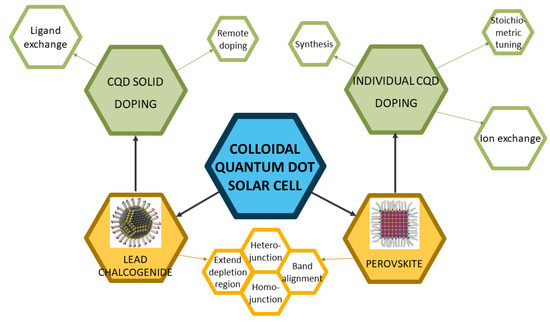
Figure 1.
The overall framework of this review. Reprinted with permission from [7,8]. Copyright 2015 and 2019 American Chemical Society.
2. Candidate Materials for CQD PVs
For CQD solar cells, one needs to consider the bandgap in order to acquire higher-efficiency cells. The Shockley–Queisser limit shown in Figure 2 indicates that there are two specific bandgap values one can take advantage of, the 1.16 eV and 1.37 eV positions. When a particular type of semiconductor is shrunk to QD, the absorption edge will be blue-shifted [9]. For example, the absorption edge of bulk PbS is over 2000 nm [10], which is in the mid-infrared range. However, by making it into CQDs, the absorption edge, which is now the first excitonic peak, can be tuned into the near-infrared range (∼1000 nm). With this context, two classes of CQDs are receiving an exceptionally large amount of attention in PV research, lead chalcogenide CQDs and perovskite CQDs, because of their suitable bandgaps. Examples are shown in Table 1. This article will mainly discuss these two types of materials.
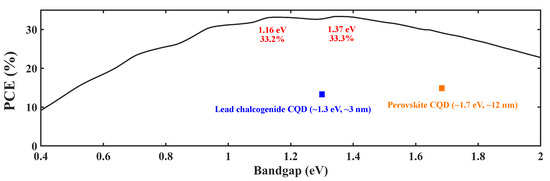
Figure 2.
Shockley–Queisser limit: PCE vs. bandgap [11].
It should be noted that PbS and PbSe CQDs are the most researched materials in lead chalcogenide CQDs. There are a few reports about PbTe CQD solar cells, and some have reached MEG in this system [12]. However, PbTe CQD solar cells will not be discussed here due to the less-competitive PCE values.

Table 1.
Examples of CQD solar cells.
Table 1.
Examples of CQD solar cells.
| CQD | Type | Bandgap | Size | PCE | Ref. |
|---|---|---|---|---|---|
| PbS | Lead chalcogenide | ∼1.34 eV | 3 nm | 11.28% | [13] |
| PbS | Lead chalcogenide | ∼1.3 eV | ∼3 nm | 12.48% | [14] |
| PbSe | Lead chalcogenide | ∼1.4 eV | ∼2.5 nm | 10.4% | [15] |
| PbSe | Lead chalcogenide | 1.37 eV | 2.5 nm | 10.38% | [16] |
| CsPbI | Perovskite | 1.75 eV | 9 nm | 10.77% | [17] |
| CsFAPbI | Perovskite | 1.64 eV | 14 nm | 16.6% | [18] |
3. CQD Doping Techniques
As previously stated, doping CQDs is challenging. There is a “self-purification” phenomenon widely existing in nanocrystals. Turnbull developed a statistical model stating that tiny crystals tend to purify themselves [19], and others attributed it to the much lower solubility of impurities in nanocrystals than in bulk semiconductors [20]. However, scientists still paved the way towards doping CQDs. The developed techniques can be generally divided into two categories: individual CQD doping (synthetic, stoichiometry tuning, and ion exchange), which is incorporating impurities within the CQDs in the colloid phase, and CQD solid doping (remote doping and ligand exchange), which is introducing the impurities to the CQD solid films.
3.1. Doping Individual CQDs
3.1.1. Doping via Synthesis
Incorporating impurities inside the QD during the synthetic process is the most straightforward way to dope CQD that one can think of. Even though, as what is stated before, according to the statistical model, tiny nanocrystals, including CQDs, are hard to dope, many scientists still have successfully achieved doped nanocrystals, and even CQDs. Quite a few scientists argue that the “self-purification” statistical model is incomplete. One fundamental assumption of this model is that the nanocrystal is in thermodynamic equilibrium with its environment, including chemical equilibrium with reservoirs of impurity and nanocrystal constituents. The atomic exchange between the reservoirs and the system must be possible [21]. Since the mid-1990s, there have been reports about doping Mn in ZnS nanocrystals in the synthesis process [22,23].
The synthesis processes of CQDs are usually hot-injection, which include hot precursors before the reaction. By injecting the reactants into the precursor quickly, nucleation is initiated due to induced supersaturation [24]. In most works of this class, the impurities will be included in the precursors. By this method, in 2000, Hoffman et al. successfully doped Mn to CdS QDs [25]. Besides Mn, Co is another dopant for CQDs that was widely researched at this stage [26]. However, both Mn and Co are isovalent dopants, which will not bring in additional carriers, as stated in the introduction. This type of doped CQDs sometimes has difficulty when applying to electronic and optoelectronic devices [27]. Thus, Ag-, Au-, Cu-, and Cd-doped InAs CQDs attracted more attention in the early 2010s [28,29]. In 2012, Norris et al. reported Ag-doped CdSe CQDs and developed thin-film transistors utilizing them. After that, other types of CQD doping methods via the synthetic route were also reported [30,31].
Successful doping on lead chalcogenide CQDs by the synthetic route has also been published. Kang et al. reported Ag doping in PbSe CQDs [32]. They tuned the dopant concentration from 5.8/dot to 63/dot, and the mobility did not change significantly with the dopant concentration. In 2013, Stavrinadis et al. reported Bi doping in PbS CQD, which enabled n-type doping with free carrier density over 1 × cm, and they built PbS CQD homojunction solar cell by utilizing this type of CQD [33]. Saha et al. also explored the Bi doping method in making heterojunction PbS CQD solar cells [34].
Even though most of the earliest doped CQDs have not been applied to any solar cells, in recent years, with the rapid development of perovskite CQD solar cell, the synthetic route has returned to the spotlight. A perovskite material is usually in the form of ABX, where A (Cs, formamidinium (FA, HC(NH)), methylammonium (MA, CHNH), etc.) and B (Pb, etc.) are the cation sites while X (normally halides) is the anion, as shown in Figure 3. Fortunately, the defect tolerance of the lead halide perovskite is very high [35,36,37,38], so perovskite CQDs are easier to dope by the synthetic route. Both isovalent and heterovalent dopants have been accomplished in the perovskite CQD system by adding additional precursors or reactants during the hot-injection process. Regarding isovalent dopants, in 2017, Prostesescu et al. reported doping the A-site with FA by mixing two different precursors [39]. Suri et al. demonstrated alloying of the X-sites by introducing multiple PbX reactants during synthesis [40]. Yao et al. reported doping of the B-site with Sr by using strontium halide as the reactant [41], and successfully blue-shifted the first excitonic peak for more than 100 nm. Similar dopants, such as Mn, have also been reported [42,43]. It should be noted that Ni is another B-site dopant accomplished through the synthetic route, but it will cause red-shift because the smaller size of Ni will bring lattice contraction [44]. Heterovalent doping was achieved by Pan et al. by demonstrating that the lanthanide dopants will change the bandgap and create additional in-gap states [45].
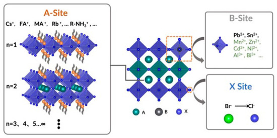
Figure 3.
Illustration of the structure of perovskite. Reprinted from [46] with permission from Creative Commons CC BY 4.0 license http://creativecommons.org/licenses/by/4.0/ accessed on 5 February 2022.
Table 2 summarizes iconic examples of CQD doping by synthesis from previous reports. The lead chalcogenide CQDs are listed more similar to traditional semiconductors (doping type, mobility, free carrier concentration, etc.). The perovskite CQD research community typically focuses more on the bandgap and band structure, so the perovskite-CQD part of the table showcases this information. The rest tables of this article also conveys information in this way.
Table 2.
Significant examples of the doping effect by synthesis.
3.1.2. Doping via Stoichiometry Tuning
Stoichiometry is another factor that can be manipulated to dope the CQDs. The stoichiometry of a semiconductor indicates the vacancies, dangling bonds, etc., in materials. Thus, it is strongly associated with doping and trap sites [49,50]. The stoichiometric-imbalance-originated doping has been well researched in bulk lead chalcogenides [51,52,53]. In 2013, Oh et al. from the Kagan group demonstrated that by evaporating excessive Pb or Se on the surface of PbSe CQDs, as shown in Figure 4a, the free carrier concentration would dramatically change [54]. Extra Pb deposition will make the film n-type, while Se will cause the p-type behavior. This strategy can tune the free carrier concentration from 10 cm to 10 cm. PbSe CQD solar cells based on this strategy were also developed, as demonstrated in Figure 4b. The Kagan group also extended this strategy to other nanomaterials such as CdSe nanocrystals [55]. Balazs et al. from the Loi group also reported that by tuning the S content of PbS quantum dots, density of states will change [56].
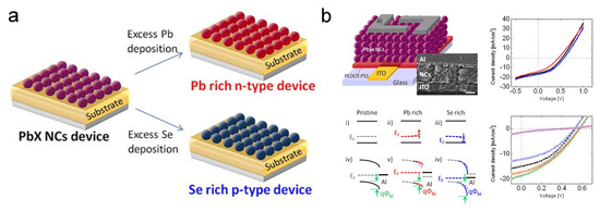
Figure 4.
(a) Illustration of tuning stoichiometry of PbX CQD. (b) Characterization of PbSe CQD solar cells with different stoichiometry. Reprinted with permission from [54]. Copyright 2013 American Chemical Society.
3.1.3. Doping via Post-Treatment Ion Exchange
Besides the synthesis process, ion exchange can also be achieved in the after-synthesis processes, generally in the colloid phase. By simply adding external ions to CQD colloids (usually in an inert atmosphere), some reactions will happen to accomplish the ion exchange. Some of the earliest keystone works in this category are by the Banin group [28,57]. They utilized the interstitial–substitutional diffusion mechanisms and selected the dopants by the diffusion coefficient. The metals with a diffusion coefficient that is larger than the self-diffusion coefficient are considered as “fast” diffusers. The diffusion will thus happen at room temperature. The Banin group reported Au, Ag, and Cu doping of InAs CQDs.
The post-treatment ion exchange strategy has been utilized in lead chalcogenide CQDs. In 2016, Lan et al. reported a molecular-level exchange on PbS CQDs by using the redox reaction of PbS + I = PbI + S [58]. However, in this paper, the I substitution is just for surface passivation. Both first excitonic peaks and free carrier concentrations remain the same. Stavrinadis et al., at the Konstantatos group, used the atomic iodine to dope PbS CQDs and successfully reduced deep traps [59]. Even though the free carrier concentration is not reported in this paper, the absorption spectrum clearly shows that the position of the first excitonic peak was shifted. Thus, successful electronic doping can be expected.
Post-treatment ion exchange doping is receiving more and more attention from the research community of perovskite CQDs in recent years because of its ease in operation. The doping method is easy and fast, especially for the A- and X-sites doping. By simply mixing and stirring two types of perovskite CQDs with different A-sites, alloying will happen. In 2018, Hazarika et al. reported that post-treatment ion exchange could tune the ratio of Cs and FA, and the emission peak can be altered in a 150 nm range [60]. Regarding the X-site, ion exchange can be achieved by adding precursors. In 2015, Nedelcu et al. and Akkerman et al. independently reported doping/alloying halogen atoms to perovskite QDs by simple solution-phase post-treatment after synthesis [61,62]. This reaction will finish in just seconds. Technically, the B-site ion exchange can also be achieved by adding additional precursors, but it takes a much longer time. Van der Stam et al. reported isovalent doping of Mn, Cd, Zn, etc., by post-treatment ion exchange, and the first excitonic absorption peak can blue-shift up to 60 nm [63]. However, the post-treatment took 16 h.
Significant CQD doping results by post-treatment ion exchange are shown in Table 3.
Table 3.
Significant examples of the doping effect by post-treatment ion exchange.
3.2. Doping CQD Solids
3.2.1. Remote Doping
Remote doping is another approach to dope CQDs. Instead of placing impurities inside the dots or on their surfaces, remote doping involves injecting charges from another adjacent material to the target material. This method was developed decades ago and was initially used in heteroepitaxial layers to obtain high-mobility two-dimensional electron gases [64]. It was then utilized in other systems, e.g., nanowires [65]. In the early 2000s, the Guyot-Sionnest group performed extensive research into charge injection to CQD solid film by electrochemical method [66,67]. The behaviors and properties of the CQDs are highly correlated with the surface conditions. Some even suggest that QDs are inherently surface-dominated [50]. By remote doping, the surface condition of the CQD solid can be kept most desirably. Moreover, remote doping will not interfere with the inter-dot spacing and film order [68]. A natural method one can think of to easily remote-dope CQD solids is by placing additional molecules in the solid matrix. The Guyot-Sionnest group is also one of the pioneering groups in developing this method. In 2000, Shim et al. successfully achieved remote doping of CdSe QDs by adding sodium biphenyl reagent, which turned the CQDs to n-type [69]. Even though this remote doping strategy is demonstrated in colloids, it verified the capacity of remote doping in film by alkali. Following this work, Yu et al. presented an n-type CdSe CQD film by evaporating K onto the CQD solid to enable remote doping [70]. In this work, the authors increased the conductance of the film by two orders of magnitude by remote doping. Since then, different chemicals have been introduced to remote doping, such as redox buffer [71], cobaltocene [72], and metal–organic complex [68]. Successful QD solar cells have been developed by the remote doping technique, e.g., PbS CQD solar cell [68] and peroskite CQD solar cell [73].
Since QD is known as the “artificial atom”, by constructing CQD superlattice and doping hetero-nanocrystals, one can achieve similar doping behavior to that in bulk silicon. The Murray group built a binary superlattice of the doping target CQD and another nanocrystal. In 2007, Urban et al. reported PbTe/AgTe thin films which behave as p-type semiconductors, and the conductivity of the thin-film increased by four orders of magnitude [74]. In their following work, CdSe CQDs and Au nanoparticles with similar sizes were used in this superlattice system to achieve substitutional doping [75]. Moreover, PbSe CQDs are also doped in the same way by simple mix and spin coating, as shown in Figure 5. The black dots in the SEM picture (Figure 5a) are the dopant nanoparticles, and Figure 5b shows the doping effect [76].

Figure 5.
(a) TEM picture showing the dopants in the PbSe superlattice. (b) Illustration of AuAg NP-doped PbSe superlattice film and the doping effect. Reprinted with permission from [76]. Copyright 2018 American Chemical Society.
3.2.2. Ligand Exchange
To stabilize CQDs in colloids (keeping CQDs isolated from each other), molecules will be capped outside the CQDs during the synthesis, which are identified as ligands. Usually, these ligands are long-carbon-chain molecules such as oleic acid and oleylamine. While the molecules keep the mixture as a colloid, the large lengths of them (>1 nm) will block the carrier from hopping/tunneling from one QD to another after making them into solids. Thus, normally these long ligands will be exchanged to small molecules or ions to enhance carrier transport when fabricating electronic or optoelectronic devices. Since CQDs’ behavior is highly sensitive to their surfaces, one can imagine that by tuning the ligands, the free carrier concentration of the CQDs will alter. Since the ligand exchange is necessary for CQD device fabrication, many researchers introduced different ligands to easily change the doping of the CQD solid without adding extra procedures, especially for lead chalcogenide CQDs. Unlike other doping strategies, the ligand exchange method is quite device-oriented. Talapin and Murray are some of the earliest pioneers working on this route. In 2005, they reported hydrazine ligand exchange on the PbSe CQD solid. The hydrazine-treated CQDs will behave as n-type, while after mild vacuum heating treatment (100 °C), the film will turn to p-type [77]. The Sargent group then contributed extensive investigations in this route by seeking shorter and more controllable ligands to reach more desirable optoelectronic properties. In 2008, Klem et al. reported that by applying dithiol ligands (ethanedithiol (EDT)) on the PbS CQDs, the solid would be p-type with a free carrier concentration of 2 × cm[78]. Three-mercaptopropionic acid (MPA) is another molecular ligand widely used in ligand exchange. It is initially applied in CdSe CQDs [79], and then was introduced to lead chalcogenide CQDs [80,81]. MPA will lead to p-type doping with free carrier concentration at the same order of magnitude with PbS-EDT ( cm), but the mobility of PbS-MPA (5.1 × 10 cm/V·s) is much larger than that of PbS-EDT (2.4 × 10 cm/V·s) [82]. This feature brought broader application of PbS-MPA in early CQD solar cells because mobility is always the bottleneck for CQD solids. Higher mobility will drastically increase the short-circuit current (I). Halide ligand exchange was then identified as an effective method to realize doping with relatively low free carrier concentration. Tang et al. first reported this technique accomplished by layer-by-layer deposition with simultaneous ligand exchange [83]. By spin-coating and treating the PbS CQD film by solutions of halide ionic compound layer by layer, most of the ligands outside the CQD will be replaced by halide ions (Figure 6a). With the atomic length of halide ions, better carrier transport between QDs can be expected. In this work, the PbS CQD solid is p-type doped ( cm), and the mobility is 4 × 10 cm/V·s. The Sargent group then realized n-type halide ligand PbS CQD solids by processing the solid in an inert atmosphere or using iodide ligands from tetrabutylammonium iodide (TBAI) in air [84,85].

Figure 6.
(a) Illustration of layer-by-layer ligand exchange. Reprinted with permission from [81,83,86,87]. Copyright 2013 John Wiley & Sons, Inc., 2010 AAAS, 2011 Nature Publishing Group, and 2009 AAAS. (b) Illustration of single-layer ink spin coating. Reprinted with permission from [13,86,88]. Copyright 2013 John Wiley & Sons, Inc., 2017 American Chemical Society, and 2017 Nature Publishing Group.
Kovalenko et al. reported another type of ligand, the metal–chalcogenide complex (MCC), such as SnS (right panel of Figure 6a) and SnSe, by simply mixing and stirring [87]. In the following years, the Talapin group reported more MCC ligands, such as InSe and AsS[89,90,91,92]. CQD solids with MCC ligands showed n-type doping behavior and amazing mobilities of over 1 cm/V·s [87,90]. This class of ligands can increase the conductivity of CQDs by 100-fold [93]. Ligands derived from the MCC, such as halide perovskite complex, are also utilized for CQDs [94], and phase-transfer ligand exchange strategy is also developed for MCC [95]. It should be noted that these ligand exchange methods, such as the phase-transfer method, usually happen in the colloid phase rather than the solid phase. Thus, they are more similar to a “doping individual CQD”. However, because their goal is still accomplishing ligand exchange to make CQD solids, we still categorize them as methods in the ligand exchange route.
The halide ligand exchange was then developed to more advanced forms to replace the layer-by-layer technology. Ning et al. reported a phase-transfer method to accomplish halide ligand exchange in solutions [96]. This strategy was further developed by Liu et al. and Lin et al., as shown in Figure 6b [13,88]. Wang et al. then reported halide ligand exchange during the CQD synthesis [97].
Significant CQD doping results by ligand exchange are shown in Table 4.
Table 4.
Significant examples of the doping effect by ligand engineering.
4. CQD Doping Mechanisms for PVs
In this section, the mechanisms of ligand exchange and remote doping are explained. Since the ion exchange process in perovskite CQDs is unique, the mechanism of this process will also be described. Furthermore, oxygen-related doping will also be involved here. Even though it is not a controllable doping process for CQDs, it is still a critical doping mechanism that cannot be ignored, because it is highly correlated with CQDs’ electrical and optical properties.
As stated before, the free carrier concentration of CQDs is dominated by surface chemistry. Surface oxidation is widely believed to be a source of p-type dopants [49]. Thanks to the XPS technology, researchers can dig deep into the surface phenomena of CQDs [78,101]. Based on the research works about oxidation of bulk PbS [102,103], early understandings usually attributed the p-type doping behaviors to the PbO, PbSO, and PbSO [78]. Zherebetskyy et al. and Cao et al. reported another oxygen-related group on the PbS CQD surface, the Pb–OH [104,105]. Using Kelvin-probe force microscopy technology and DFT simulation, the Alivisatos group raised the point that molecular oxygen will induce in-gap states, as shown in Figure 7 [106,107,108].
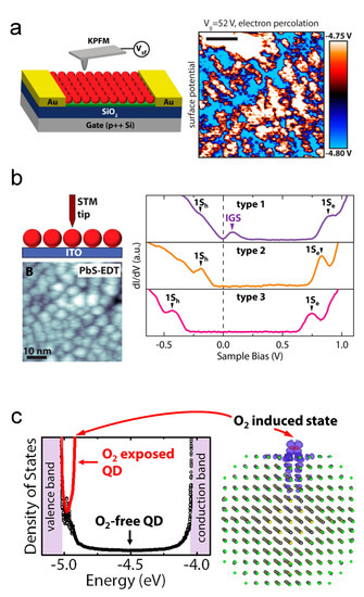
Figure 7.
Oxygen-related doping mechanisms: (a) KPFM characterization of percolation pathways by in-gap states in PbS QD solid. (b) STM characterization of in-gap states in PbS QD solid. Reprinted with permission from [106]. Copyright 2015 American Chemical Society. (c) Illustration of in-gap states induced by molecular oxygen. Reprinted with permission from [107]. Copyright 2015 American Chemical Society.
Based on the results produced by the powerful tool DFT simulation, Voznyy et al. built a charge-orbital model to investigate the CQD doping, as shown in Figure 8a,b [109]. They raised the opinion that oxygen is the acceptor while the halide atomic ligands act as the donor. In 2020, Meng et al. revisited the doping phenomenon [100]. By XPS investigation, they researched the mechanism of different p-type doping concentrations and found that the Pb–OH will absorb the protons (H) in the solution that contains shorter ligands. The Pb–OH·H groups are the donors in PbS CQD solids, and the halide donors will compensate the p-type dopants, as shown in Figure 8c,d.

Figure 8.
Ligand exchange doping mechanisms: (a) Illustration of doping effect caused by a potassium ion and an iodide ion. (b) Free carrier concentrations of PbS QDs with different ligands. Reprinted with permission from [109]. Copyright 2012 American Chemical Society. (c) Illustration of surface conditions of PbS QD with different ligand exchange process. (d) Hypotheses of mechanism of ligand-exchange-induced doping. Reprinted with permission from [100]. Copyright 2020 American Chemical Society.
The earliest reports about remote doping are all from the electrochemical route. The Guyot-Sionnest group made tremendous efforts in this route. In an electrochemical redox reaction, if a CQD film is placed on the working electrodes, the applied voltage will control the Fermi level of the CQD film. Thus, electrons can be injected into or taken out of the CQD film from electrically tuned Fermi levels [67]. The advantage of this method is that the amount of injected charges can be accurately controlled. An example can be seen from Figure 9a: by electrochemical reaction in the decamethylferrocene/decamethylferrocenium redox buffer, positive charges were injected into the PbSe CQD film. Nowadays, most researchers abandon the actual electrochemical reaction. For example, as shown in Figure 9b, by placing Ag nanoparticles in PbSe CQD superlattice, electrons can be directly injected into the CQDs because the Fermi level of Ag is above PbSe CQD [76].
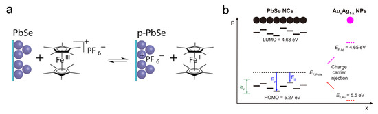
Figure 9.
Remote doping mechanisms: (a) Illustration of PbSe CQD remote doping by redox buffer. Reprinted with permission from [71]. Copyright 2012 American Chemical Society. (b) Illustration of PbSe CQD remote doping by AuAg NPs. Reprinted with permission from [76]. Copyright 2018 American Chemical Society.
As stated previously, most of the dopants in perovskite CQDs are isovalent, which means they are more similar to alloys. To investigate the lattice substitution, the most fundamental figure-of-merit is the Goldschmidt tolerance factor (GTF) [110]. In the perovskite ABX structure (Figure 3), the GTF can be expressed as , where is the effective ionic radius. With GTF between 0.9–1.0, the structure will be ideal cubic, while GTF values of 0.8–0.9 will lead to perovskite structure with tilting of the BX octahedra [60,111]. Technically speaking, all site substitutions (A, B, and X) will alter the band structure of perovskite CQDs. Nevertheless, the B- and X-site substitution will dramatically change the bandgap [111].
According to the Goldschmidt theory, the A-site dominates the lattice distortion, etc., based on the size of the A component. The lattice change will consequently bring change in the band structure. Even though the tuning range might not be that large, it is still worth investigating. The B component will form the [BX] octahedron together with the X component, dominating the valence and conduction bands. Other than the electronic doping, according to the Goldschmidt theory, the B-site will also contribute to the perovskite CQDs’ stability and toxicity (Pb is considered toxic). Thus, although the B-site is not as easily ion-exchanged as A- and X-sites, researchers are still developing methods to dope this site. Doping the X-site is the most widely used strategy to tune the band structure of perovskite CQDs because it is an easier process compared to those of the other two sites, and the tuning range can be as large as 200 nm [62].
5. Milestones for Doping in CQD PVs
The first CQD solar cell was born in 1998; an InP QD/TiO junction was built to achieve it [112]. InP is a III-V compound, and this class of materials is still utilized in CQD solar cells such as binary III-V compound CQDs or even ternary ones [113,114,115]. McDonald et al. then developed a PbS CQD/organic semiconductor solar cell [116]. After that, lead chalcogenide CQDs have been widely utilized as the photoactive layer in solar cells [117,118,119,120,121,122,123]. However, because of insufficient CQD thin-film technologies, devices in these early works usually possessed poor film morphology, and the band structures were not well tuned. Consequently, the external quantum efficiency (EQE) values are not ideal. After the CQD/TiO(ZnO) heterojunction was introduced, different high-efficiency CQD solar cells were developed [80,124,125,126,127], among which the highest PCE value has exceeded 5%.
In 2010, Pattantyus-Abraham et al. first reported free carrier concentration in a CQD solar cell that utilized PbS-MPA (PbS CQD solid with MPA ligands, following a similar expression to here) [80]. In 2011, Tang et al. reported free carrier concentration in QD solar cells with halide ligands [83]. The details of the device and key results are shown in Figure 10a. As can be seen from the figure, the device is based on a TiO/PbS CQD heterojunction. The values of free carrier concentrations are retrieved by Mott–Schottky analysis, which is a capacitance–voltage measurement, and the PCE of the device has surpassed 5%. Ip et al. reported free carrier concentration in QD solar cells with hybrid ligands using the same analytical method [128]. Devices at that time were mainly heterojunction devices with heavily n-type-doped oxides such as TiO and ZnO. Thus, researchers did not have such urgent needs to precisely tune doping in CQD. As more complicated CQD solar cells emerged, such as tandem CQD solar cells [129], doping CQD became more and more important.
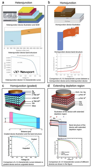
Figure 10.
Key graphs of iconic lead sulfide CQD solar cells. Every panel shows the device structure, band structure, and I–V (J–V) curve of the device: (a) Heterojunction PbS CQD solar cell. Reprinted with permission from [83]. Copyright 2011 Nature Publishing Group. (b) Homojunction PbS CQD solar cell by adding PbS-EDT for band alignment. Reprinted with permission from [130]. Copyright 2014 Nature Publishing Group. (c) Homojunction PbS CQD solar cell by graded structure (n-n-p) for band alignment. Reprinted with permission from [131]. Copyright 2013 John Wiley & Sons, Inc. (d) PbS CQD solar cell with lightly doped photoactive layer to extend the depletion region. Reprinted with permission from [99]. Copyright 2013 John Wiley & Sons, Inc.
In 2014, Bawendi et al. reported a CQD solar cell of which the PCE reached 8.55%, setting a new world record for QD solar cells by then, as shown in Figure 10b [130]. They raised a critical strategy, band alignment. The core idea is that to accomplish better carrier retrieval, one needs to carefully design the band structure to avoid unwanted barriers or wells and achieve a step-like shape. In this work, by building a PbS CQD homojunction as shown in the top and middle panels of Figure 10b, the authors obtained a more efficient carrier retrieval structure. They utilized the PbS-EDT as the p-type semiconductor layer and PbS-TBAI as the n-type semiconductor layer. The bottom panel of Figure 10b shows a large performance increase in the J–V curve comparison between a homojunction device and a heterojunction device. Ning et al. from the Sargent group even reported graded doping devices by constructing a p+-n-n+ PbS CQD structure (Figure 10c) [131]. Many other researchers have also played with this graded doped charge extraction structure. For example, Bederak et al. utilized PbS–Cl as the p-type layer and boosted the device efficiency [132]. As we know, because CQDs are extremely tiny nanocrystals, the surface areas of CQD solids are large. The large surface areas will certainly bring advantages to some applications of CQDs; however, for every plus, there is a minus. The large surface area makes CQDs more reactive in the ambient environment, which means they are prone to be oxidized in air. For n-type CQDs, because the Fermi levels are higher, they are even more unstable in the air than p-type CQDs. Thus, making air-stable n-type CQD solids suitable for solar cells is not that easy. In 2014, Ning et al. researched PbS CQDs with iodide ligand brought by TBAI [98]. TBAI will provide a more thorough ligand-exchanged CQD surface, leading to n-type doping (less attacked by oxygen) and better air stability. In this way, inverted structure PbS CQD solar cells were developed. Different types of halide ligands have been applied to lead sulfide CQDs in the following years. Lan et al. utilized methylammonium iodide (MAI) as the ligands and reached a world-record-high PCE of 10.6% by then [133]. The PbS CQD ink’s (phase-transfer ligand exchange) doping concentration has also been tuned by adding fluorides to the matrix to obtain a better band alignment with the ZnO [134].
Another motivation to tune the doping is to obtain more lightly doped CQDs. Lighter doping will extend the depletion region. Due to the built-in potential, the bands in the depletion region will be bent. Bent bands will help in the charge separation process. Thus, a wider depletion region means we can have more band-bent width to separate charges more effectively. Consequently, we would like the photoactive CQD layers to be lightly doped. Yuan et al. reported that by tuning the molecular ligands to 3MBA ( cm), they can obtain a lightly p-type-doped CQD solid (Figure 10d) [99]. By utilizing a graded structure, a 7.2% device was reached, which is considerably higher than highly doped MPA devices, as shown in the J–V curve in the bottom panel of Figure 10d.
Besides ligand-exchange engineering, progress has also been made in lead chalcogenide CQD solar cells doped by other methods. Stavrinadis et al., at the Konstantatos group, developed a synthetic approach to dope PbS CQDs by Bi and achieved n-type CQDs. Using this CQD, they successfully built a PbS CQD homojunction solar cell and reached a PCE of 2.7%. As shown in Figure 4, PbSe CQD solar cells doped by stoichiometry tuning have also been made, and the PCE is 3.85% [54]. Post-treatment ion exchange has been chiefly applied to suppress trap states to make high-efficiency PbS CQD solar cells [58,59]. Moreover, remote doping has also been used to develop PbS CQD solar cells, and the PCE reached 7.8% [68].
The iconic works of lead chalcogenide CQD solar cells accomplished by doping engineering are listed in the Table 5 below.
Table 5.
Summary of high-efficiency lead chalcogenide CQD solar cells by doping engineering.
Perovskite has been a star solar material since its first application in solar cells in 2009 [135]. The world has seen that the PCE of single-junction perovskite solar cells increases from the earliest 3.8% to 25.5% in 2021 [136] and the stability is also enhanced dramatically [137,138]. Consequently, the perovskite CQDs have also been considered candidates for quantum dot solar cells. As has been stated, QDs will lead to MEG (multiple excitons generated by one photon) because of the Auger recombination process. Scientists have been hoping to surpass the perovskite solar cell record, or even the Shockley–Queisser limit, with perovskite CQDs, and the perovskite CQDs also bring opportunities for flexible solar cells [139]. The perovskite CQDs were synthesized back in 2014 [140]. In the following two years, their applications are primarily in light-emitting technologies [141,142,143,144]. In 2016, Swarnkar et al. from NREL first reported a perovskite CQD solar cell with the motivation of using nanocrystal surfaces to stabilize -CsPbI at room temperature [17]. Since then, researchers from this community have been making tremendous efforts to tune the doping of perovskite CQDs for seeking high-efficiency solar cells.
As there are two types of ligands on the as-synthesized perovskite CQDs [145], the ligand exchange process is not as easy as that of lead chalcogenide CQDs. However, it is still a powerful tool to enhance the performance of perovskite CQD solar cells. Various two-step and one-step methods have been developed [17,146,147,148,149,150]. Most of these works focused on surface passivation to enhance carrier transport and stability. Recently, there have been reports about tuning the band structure of the perovskite CQDs by ligand exchange. For example, Wang et al. reported adjusting the band structure of CsPbBrI by ligand amounts [151].
Figure 11a shows a typical perovskite CQD solar cell picture and SEM cross-sectional image. The devices are usually based on a heterojunction structure with a perovskite photoactive layer, an electron transporting layer (usually TiO), and a hole transporting layer (usually spiro-OMeTAD). As has been stated before, all A-, B-, and X-sites can be doped. In 2018, Hazarika et al. reported using A-site-doped perovskite CQDs with spiro-OMeTAD and TiO to construct perovskite CQD solar cells, and the highest-PCE solar cell among these devices reached 11.14%, as shown in Figure 11b [60]. In this work, FA was employed as the dopant on the A-site. The process is illustrated in Figure 11b, and it can also be noticed from this figure that the A-site doping will lead to change in PL first excitonic peak as large as 180 nm, which proves a successful doping effect, band structure modification. What can also be concluded from the Goldschmidt theory is that by altering the size of the X component, the halide atoms, one can compensate for the lattice distortion brought about by the A-site. Thus, Suri et al. demonstrated that by simultaneous doping of both A- and X-sites, the bandgap of perovskite CQD could be fine-tuned. In this way, the device showed compromised PCE (∼6%) [40], but exhibited a longer PL lifetime and increased open-circuit voltage (V) compared to mono-site doped devices, making it promising for future multi-junction solar cells. Moreover, it should be noted that the world record of CQD solar cells (published results) was made on CsFAPbI [18]. The research community has also seen B-site doped perovskite CQD solar cells. Since the B-site is highly correlated with the stability of perovskite CQDs, researchers are pretty cautious in doping this site. For example, Sn is a B-site dopant, but, typically speaking, Sn-doped CQDs are not that stable. Thus, the doping volume should be well controlled. In 2017, Liu et al. reported CsSnPbI CQD with good air stability. Even though the resulting solar cell’s PCE is just ∼2.9%, it opened the door for air-stable B-site doping [152]. In 2020, Bi et al. exhibited doping the B-site with 7% (molar ratio) of Zn, and the PCE reached 14.8%, as shown in the bottom left panel of Figure 11c [47]. Figure 11c also shows that by adding 11% of Zn, the PL first excitonic peak will move roughly 10 nm. More information about doping can be read from the band structure measured by XPS, as shown in the middle left panel of Figure 11c. We can see that with 7% of Zn doping, the Fermi level of the perovskite CQD moves downwards (E–E decreasing), which is a direct proof of p-type doping. Doping the X-site is a widely used strategy to tune the band structure of perovskite CQDs because it is a more straightforward process compared to those of the other two sites. Moreover, the tuning range can be as large as 200 nm [62]. By using this method, CsPbBr CQD solar cells have been developed, and the V can be as large as 1.5 V [153]. Christodoulou et al. applied CsPbBrI CQDs to solar cells and also reached a large V, as shown in Figure 11d [154]. SCN is another ion that has been used to achieve X-site doping. Most researchers have used it to passivate the trap sites caused by halide vacancies [155]. Solar cells have also been made by using SCN doping [48].

Figure 11.
Key graphs of iconic perovskite CQD solar cells accomplished by A-, B-, and X-site doping. Explanation of each sub-figure is shown beside it. (a) Typical device picture and SEM cross-sectional structure. (b) FA-doped (A-site) perovskite solar cell. Reprinted with permission from [60]. Copyright 2018 American Chemical Society. (c) Zn-doped (B-site) perovskite solar cell. Reprinted with permission from [47]. Copyright 2020 American Chemical Society. (d) Br-doped (X-site) perovskite solar cell. Reprinted with permission from [154]. Copyright 2018 American Chemical Society.
Heterovalent doping, which is quite similar to doping of traditional bulk semiconductors, is also essential in doping perovskite CQDs. Lanthanides popped up in the first place as it has been proven that lanthanide-doped crystals can be helpful to the light “downconversion” process because of the “quantum-cutting effect” [156]. Using this effect, researchers have reached PLQY over 100% (as high as 146%) perovskite CQD solids by doping Yb, Ce, etc. [157,158]. Applications such as downconverters [157] and solar concentrations [159] have been developed by using this strategy. In recent years, the effects of heterovalent dopants on the band structures are also widely researched. Begum et al. reported that the Bi dopants would change the positions of both conduction band and valence band, and bring trap states [160]. In 2019, the Sb-doped perovskite CQD solar cell was reported by Bera et al., as shown in Figure 12a [161]. They demonstrated improved PCE (9.4%) and stablized crystal phase by introducing Sb.
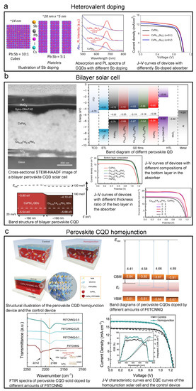
Figure 12.
Key graphs of iconic perovskite CQD solar cells accomplished by heterovalent doping, bilayer structure, and homojunction structure. Explanation of each sub-figure is shown beside it. (a) Perovskite CQD solar cell with heterovalent doping. Reprinted with permission from [161]. Copyright 2019 American Chemical Society. (b) Bilayer-structured perovskite CQD solar cell. Reprinted from [162] with permission from Creative Commons CC BY 4.0 license http://creativecommons.org/licenses/by/4.0/ accessed on 5 February 2022. (c) Perovskite CQD homojunction solar cell. Reprinted with permission from [73]. Copyright 2022 John Wiley & Sons, Inc.
As the doping of perovskite CQDs is quite deeply investigated, bilayer structured solar cells with differently doped CQD solids have been developed. By two differently doped CQD layers, one can achieve a favorable energy landscape to better extract charge carriers. In 2018, Bian et al. demonstrated a bilayer perovskite CQD solar cell with CsPbI QD and CsPbIBr crystalline layers with SCN modification, and the PCE reached over 14% [48]. Zhao et al. then developed bilayer solar cells with A-site-doped perovskite CQD, CsFAPbI, and CsPbI CQD. The device achieved a PCE of 15.52%, as shown in the top left panel of Figure 12b [162]. In this work, the authors designed this structure from a comprehensive investigation into the FA A-site doping by band structure measurement, as shown in the top right panel of Figure 12b, and the resulted bilayer band structure is also shown in Figure 12b. Besides the aforementioned works, Li et al. from the Ma group fabricated a CsPbI:FAPbI (CsFAPbI will be formed at the interface) structured device and reached a PCE of 15.6% [163].
Recently, the CQD homojunction structure was also introduced to the perovskite CQD solar cell by Zhang et al. (Figure 12c) [73]. By remote doping by 2,2-(perfluoronaphthalene-2,6-diylidene) dimalononitrile (F6TCNNQ), as shown in the top left panel of Figure 12c, they achieved a p-type CsPbI CQD solid. By tuning the concentration of F6TCNNQ, the Fermi level can be largely lowered without changing the CBM and VBM on a large scale. By combining this p-type layer with the normal n-type CsPbI layer, they successfully built a CsPbI homojunction and enabled an over 1 m thick photoactive layer. The PCE reached 15.29%, as shown in the bottom right panel of Figure 12c.
The iconic works of perovskite CQD solar cells accomplished by doping engineering are listed as in Table 6 below.
Table 6.
Summary of high-efficiency perovskite CQD solar cells by doping engineering.
6. Summary and Future Perspectives
The CQDs have their unique advantages in semiconductor academia and industry. The nm size brings them sharp absorption/emission peaks and MEG effect, which are desirable properties for displays and solar cells. The QD displays have been commercialized by now. Furthermore, CQDs can be deposited by various printing technologies, which will bring up opportunities in cost-effective mass production [6]. Their polycrystalline nature makes them possible for future flexible devices; however, there are also disadvantages lying in CQDs. The large surface areas will lead to severe stability issues. Moreover, since, currently, the manufacturing technologies in creating CQD devices are limited, device reproducibility is also not ideal.
In this article, we comprehensively reviewed the doping of colloidal quantum dots and their application in quantum dot photovoltaics from the perspectives of doping strategies, mechanisms, and milestone works in CQD solar cells. The lead chalcogenide CQD solar cells and the perovskite CQD solar cells are taken as examples. The record PCE has increased to 18.1% from less than 4%. Doping engineering plays an essential role in this soaring efficiency increase. The strategies are categorized into five types (synthesis, stoichiometry tuning, post-treatment ion exchange, remote doping, and ligand exchange) for discussion. The mechanism part focuses on the more unique doping mechanisms in CQDs. Milestone works utilizing doping engineering to increase CQDs solar cells’ performance are also discussed.
Even though tremendous progress has been made in this research community, there are still challenges to be completed and future trends to be caught up with. Here, we list them below:
(1) Doping engineering in CQD ink: Spray printing is the most widely utilized method in printing CQDs because of its ease to be automated and assembled in a “junkyard war fashion”. There have been quite a few reports on this technology [164,165], and it can be integrated into an R2R process [166]. Other processes, such as blade coating and inkjet printing, were also investigated [167,168,169]. The PCE of devices made by these printing technologies have surpassed 8%. However, the lack of doping tuning strategies for CQD inks limits the choices of materials towards higher-efficiency devices. Thus, tuning CQD inks’ doping still needs to be further investigated.
(2) Doping tuning to integration with silicon: One of the future opportunities of CQD photovoltaic devices comes from their integration with conventional silicon devices. The spray printing, blade coating, and inkjet printing are all compatible with Si surfaces and the CMOS process. Recently, many researchers have touched on this area to exploit the potential of integration of CQDs with Si [170,171,172,173,174]. This technology has been commercialized by now [175]. Because the bandgap of lead chalcogenide CQD can be tuned to the infrared absorption range, it can be a candidate to extend the absorption bandwidth of current Si solar cells to further increase PCE. The Sargent group has carried out extensive preliminary works on this topic [176,177,178,179,180]. However, to reach such a complex Si:CQD structure, the doping of the CQDs should be well adjusted to fit the band structure of the whole cell. Besides Si solar cells, this heterostructure will also benefit the perovskite solar cell [181] and photodetector research [182,183]. Of course, other issues, such as interface [172,184], are also crucial, but they will not be discussed here.
(3) Comprehensive investigation in doping of perovskite quantum dots: Perovskite CQDs are initially developed for light-emitting applications. Thus, the investigation regarding electronic properties (mobility, etc.) is lagging behind light-emitting related properties. However, electronic properties are important figure-of-merits in photovoltaic research. Thus, the challenging problems still stand: How can we tune the doping concentration freely without (much) sacrifice of mobility? How can we increase the dopant concentration without bringing up too many trap states?
(4) Novel materials and structures for perovskite CQD solar cells: As we can see from previous reports, the structures of all perovskite CQD solar cells are similar. By further optimizing the structure and importing new materials suitable for the structure, higher PCE, or even PCE over the Shockley–Queisser limit, can be expected. Recently, the Ma group first reported the perovskite QD homojunction in solar cells [73]. In the future, the homojunction structure can be further optimized by importing more suitable materials and switching to other doping methods, and even graded-doped devices, such as those of lead chalcogenide CQDs [131], can be developed to reach the holy grail.
Funding
This article was funded by Natural Sciences and Engineering Research Council of Canada (NSERC Discovery Grant program; RGPIN-2019-04664).
Institutional Review Board Statement
Not applicable.
Informed Consent Statement
Not applicable.
Acknowledgments
X.W. would like to thank Natural Sciences and Engineering Research Council of Canada for funding support.
Conflicts of Interest
The authors declare no conflict of interest.
Nomenclature
The following abbreviations are used in this manuscript:
| CIGS | Copper indium gallium selenide |
| FA, HC(NH | Formamidinium |
| MA, CHNH | Methylammonium |
| EDT | ethanedithiol |
| MPA | 3-mercaptopropionic acid |
| I | Short-circuit current |
| TBAI | Tetrabutylammonium iodide |
| CTAB | Cetyltrimethylammonium bromide |
| r | Effective ionic radius of ions in ABX-structured perovskite |
| V | Open-circuit voltage |
| MAI | Methylammonium iodide |
| 3MBA | 3-Methoxybenzamide |
| TBAB | Tetrabutylammonium bromide |
| TMAH | Tetramethylammonium hydroxide |
| EMII | 1-ethyl-3-methylimidazolium iodide |
| SCN | Thiocyanate ion |
| F6TCNNQ | 2,2-(perfluoronaphthalene-2,6-diylidene) dimalononitrile |
| Spiro-OMeTAD | 2,2′,7,7′-Tetrakis[N,N-di(4-methoxyphenyl)amino]-9,9′-spirobifluorene |
| PTAA | Poly[bis(4-phenyl)(2,4,6-trimethylphenyl)amine |
| E | Vacuum level, the energy of a free stationary electron that is outside of any material |
| E | Fermi level |
| CBM, E | Conduction band minimum, the lowest edge of the conduction band of a semiconductor |
| VBM, E | Valence band maximum, the highest edge of the valence band of a semiconductor |
| W | Width of the depletion region |
| ITO | Indium doped tin oxide |
| FTO | Fluorine doped tin oxide |
References
- Friedlingstein, P.; O’sullivan, M.; Jones, M.W.; Andrew, R.M.; Hauck, J.; Olsen, A.; Peters, G.P.; Peters, W.; Pongratz, J.; Sitch, S.; et al. Global carbon budget 2020. Earth Syst. Sci. Data 2020, 12, 3269–3340. [Google Scholar] [CrossRef]
- Renewable Energy Market by Type (Hydroelectric Power, Wind Power, Bioenergy, Solar Energy, and Geothermal Energy) and End Use (Residential, Commercial, Industrial, and Others): Global Opportunity Analysis and Industry Forecast, 2021–2030. Allied Market Research. Available online: https://www.alliedmarketresearch.com/renewable-energy-market (accessed on 5 February 2022).
- Stanford University Global Climate & Energy Project Analysis Activities: Exergy Flow Charts. Available online: http://gcep.stanford.edu/research/exergycharts.html (accessed on 20 March 2022).
- NREL Best Research-Cell Efficiency Chart. Available online: https://www.nrel.gov/pv/cell-efficiency.html (accessed on 7 December 2021).
- Rühle, S. Tabulated values of the Shockley–Queisser limit for single junction solar cells. Sol. Energy 2016, 130, 139–147. [Google Scholar] [CrossRef]
- Sargent, E.H. Colloidal quantum dot solar cells. Nat. Photonics 2016, 6, 133–135. [Google Scholar] [CrossRef]
- Yang, Z.; Voznyy, O.; Liu, M.; Yuan, M.; Ip, A.H.; Ahmed, O.S.; Levina, L.; Kinge, S.; Hoogland, S.; Sargent, E.H. All-quantum-dot infrared light-emitting diodes. ACS Nano 2015, 9, 12327–12333. [Google Scholar] [CrossRef]
- Zhang, B.B.; Yuan, S.; Ma, J.P.; Zhou, Y.; Hou, J.; Chen, X.; Zheng, W.; Shen, H.; Wang, X.C.; Sun, B.; et al. General mild reaction creates highly luminescent organic-ligand-lacking halide perovskite nanocrystals for efficient light-emitting diodes. J. Am. Chem. Soc. 2019, 141, 15423–15432. [Google Scholar] [CrossRef]
- Neeleshwar, S.; Chen, C.L.; Tsai, C.B.; Chen, Y.Y.; Chen, C.C.; Shyu, S.G.; Seehra, M.S. Size-dependent properties of CdSe quantum dots. Phys. Rev. B 2005, 71, 201307. [Google Scholar] [CrossRef] [Green Version]
- Schoolar, R.B.; Dixon, J.R. Optical constants of lead sulfide in the fundamental absorption edge region. Phys. Rev. 1965, 137, A667. [Google Scholar] [CrossRef]
- Miller, O. Shockley Queisser Limit. Available online: https://www.mathworks.com/matlabcentral/fileexchange/43879-shockleyqueisser (accessed on 19 December 2021).
- Böhm, M.L.; Jellicoe, T.C.; Tabachnyk, M.; Davis, N.J.; Wisnivesky-Rocca-Rivarola, F.; Ducati, C.; Ehrler, B.; Bakulin, A.A.; Greenham, N.C. Lead telluride quantum dot solar cells displaying external quantum efficiencies exceeding 120%. Nano Lett. 2017, 15, 7987–7993. [Google Scholar] [CrossRef] [Green Version]
- Liu, M.; Voznyy, O.; Sabatini, R.; García de Arquer, F.P.; Munir, R.; Balawi, A.H.; Lan, X.; Fan, F.; Walters, G.; Kirmani, A.R.; et al. Hybrid organic–inorganic inks flatten the energy landscape in colloidal quantum dot solids. Nat. Mater. 2017, 16, 258–263. [Google Scholar] [CrossRef]
- Xu, J.; Voznyy, O.; Liu, M.; Kirmani, A.R.; Walters, G.; Munir, R.; Abdelsamie, M.; Proppe, A.H.; Sarkar, A.; García de Arquer, F.P.; et al. 2D matrix engineering for homogeneous quantum dot coupling in photovoltaic solids. Nat. Nanotechnol. 2018, 13, 456–462. [Google Scholar] [CrossRef]
- Hu, L.; Geng, X.; Singh, S.; Shi, J.; Hu, Y.; Li, S.; Guan, X.; He, T.; Li, X.; Cheng, Z.; et al. Synergistic effect of electron transport layer and colloidal quantum dot solid enable PbSe quantum dot solar cell achieving over 10% efficiency. Nano Energy 2019, 64, 103922. [Google Scholar] [CrossRef]
- Liu, Y.; Li, F.; Shi, G.; Liu, Z.; Lin, X.; Shi, Y.; Chen, Y.; Meng, X.; Lv, Y.; Deng, W.; et al. PbSe quantum dot solar cells based on directly synthesized semiconductive Inks. ACS Energy Lett. 2020, 5, 3797–3803. [Google Scholar] [CrossRef]
- Swarnkar, A.; Marshall, A.R.; Sanehira, E.M.; Chernomordik, B.D.; Moore, D.T.; Christians, J.A.; Chakrabarti, T.; Luther, J.M. Quantum dot–induced phase stabilization of α-CsPbI3 perovskite for high-efficiency photovoltaics. Science 2016, 354, 92–95. [Google Scholar] [CrossRef] [PubMed] [Green Version]
- Hao, M.; Bai, Y.; Zeiske, S.; Ren, L.; Liu, J.; Yuan, Y.; Zarrabi, N.; Cheng, N.; Ghasemi, M.; Chen, P.; et al. Ligand-assisted cation-exchange engineering for high-efficiency colloidal Cs1−xFAxPbI3 quantum dot solar cells with reduced phase segregation. Nat. Energy 2020, 5, 79–88. [Google Scholar] [CrossRef]
- Turnbull, D. Formation of crystal nuclei in liquid metals. J. Appl. Phys. 1950, 21, 1022–1028. [Google Scholar] [CrossRef]
- Dalpian, G.M.; Chelikowsky, J.R. Self-purification in semiconductor nanocrystals. Phys. Rev. Lett. 2006, 96, 226802. [Google Scholar] [CrossRef]
- Norris, D.J.; Efros, A.L.; Erwin, S.C. Doped nanocrystals. Science 2008, 319, 1776–1779. [Google Scholar] [CrossRef]
- Bhargava, R.N.; Gallagher, D.; Hong, X.; Nurmikko, A. Optical properties of manganese-doped nanocrystals of ZnS. Phys. Rev. Lett. 1994, 72, 416. [Google Scholar] [CrossRef]
- Kennedy, T.A.; Glaser, E.R.; Klein, P.B.; Bhargava, R.N. Symmetry and electronic structure of the Mn impurity in ZnS nanocrystals. Phys. Rev. B 1995, 52, R14356. [Google Scholar] [CrossRef]
- Carey, G.H.; Abdelhady, A.L.; Ning, Z.; Thon, S.M.; Bakr, O.M.; Sargent, E.H. Colloidal quantum dot solar cells. Chem. Rev. 2015, 115, 12732–12763. [Google Scholar] [CrossRef]
- Hoffman, D.M.; Meyer, B.K.; Ekimov, A.I.; Merkulov, I.A.; Efros, A.L.; Rosen, M.; Couino, G.; Gacoin, T.; Boilot, J.P. Giant internal magnetic fields in Mn doped nanocrystal quantum dots. Solid State Commun. 2000, 114, 547–550. [Google Scholar] [CrossRef]
- Hanif, K.M.; Meulenberg, R.W.; Strouse, G.F. Magnetic ordering in doped Cd1−xCoxSe diluted magnetic quantum dots. J. Am. Chem. Soc. 2002, 124, 11495–11502. [Google Scholar] [CrossRef] [PubMed]
- Sahu, A.; Kang, M.S.; Kompch, A.; Notthoff, C.; Wills, A.W.; Deng, D.; Winterer, M.; Frisbie, C.D.; Norris, D.J. Electronic impurity doping in CdSe nanocrystals. Nano Lett. 2012, 12, 2587–2594. [Google Scholar] [CrossRef] [PubMed] [Green Version]
- Mocatta, D.; Cohen, G.; Schattner, J.; Millo, O.; Rabani, E.; Banin, U. Heavily doped semiconductor nanocrystal quantum dots. Science 2011, 332, 77–81. [Google Scholar] [CrossRef] [Green Version]
- Geyer, S.M.; Allen, P.M.; Chang, L.Y.; Wong, C.R.; Osedach, T.P.; Zhao, N.; Bulovic, V.; Bawendi, M.G. Control of the carrier type in InAs nanocrystal films by predeposition incorporation of Cd. ACS Nano 2010, 4, 7373–7378. [Google Scholar] [CrossRef]
- Saha, A.; Makkar, M.; Shetty, A.; Gahlot, K.; Pavan, A.R.; Viswanatha, R. Diffusion doping in quantum dots: Bond strength and diffusivity. Nanoscale 2017, 9, 2806–2813. [Google Scholar] [CrossRef]
- Makkar, M.; Viswanatha, R. Frontier challenges in doping quantum dots: Synthesis and characterization. RSC Adv. 2018, 8, 22103–22112. [Google Scholar] [CrossRef] [Green Version]
- Kang, M.S.; Sahu, A.; Frisbie, C.D.; Norris, D.J. Influence of silver doping on electron transport in thin films of PbSe nanocrystals. Adv. Mater. 2013, 25, 725–731. [Google Scholar] [CrossRef]
- Stavrinadis, A.; Rath, A.K.; De Arquer, F.; Diedenhofen, S.L.; Magén, C.; Martinez, L.; So, D.; Konstantatos, G. Heterovalent cation substitutional doping for quantum dot homojunction solar cells. Nat. Commun. 2013, 4, 1–7. [Google Scholar] [CrossRef] [Green Version]
- Saha, S.K.; Bera, A.; Pal, A.J. Improvement in PbS-based hybrid bulk-heterojunction solar cells through band alignment via bismuth doping in the nanocrystals. ACS Appl. Mater. Interfaces 2015, 7, 8886–8893. [Google Scholar] [CrossRef]
- Liu, Z.; Li, F.; Huang, G.; Zhao, F.; Zhang, W.; Jiang, G.; Cheng, S.; Fang, Z.; Zhu, Q.; Huang, Y. Stability improvement of photoluminescent QLEDs based on Mn-doped all-inorganic metal halide perovskite quantum dots with silica shell. J. Alloy. Compd. 2021, 888, 161505. [Google Scholar] [CrossRef]
- Xu, L.; Yuan, S.; Zeng, H.; Song, J. A comprehensive review of doping in perovskite nanocrystals/quantum dots: Evolution of structure, electronics, optics, and light-emitting diodes. Mater. Today Nano 2019, 6, 100036. [Google Scholar] [CrossRef]
- Kang, J.; Wang, L.W. High defect tolerance in lead halide perovskite CsPbBr3. J. Phys. Chem. Lett. 2017, 8, 489–493. [Google Scholar] [CrossRef] [PubMed]
- Li, J.; Chen, J.; Xu, L.; Liu, S.; Lan, S.; Li, X.; Song, J. A zinc non-halide dopant strategy enables efficient perovskite CsPbI3 quantum dot-based light-emitting diodes. Mater. Chem. Front. 2020, 4, 1444–1453. [Google Scholar] [CrossRef]
- Protesescu, L.; Yakunin, S.; Kumar, S.; Bär, J.; Bertolotti, F.; Masciocchi, N.; Guagliardi, A.; Grotevent, M.; Shorubalko, I.; Bodnarchuk, M.I.; et al. Dismantling the “red wall” of colloidal perovskites: Highly luminescent formamidinium and formamidinium–cesium lead iodide nanocrystals. ACS Nano 2017, 11, 3119–3134. [Google Scholar] [CrossRef]
- Suri, M.; Hazarika, A.; Larson, B.W.; Zhao, Q.; Vallés-Pelarda, M.; Siegler, T.D.; Abney, M.K.; Ferguson, A.J.; Korgel, B.A.; Luther, J.M. Enhanced Open-Circuit Voltage of Wide-Bandgap Perovskite Photovoltaics by Using Alloyed (FA1–xCsx)Pb(I1–xBrx)3 Quantum Dots. ACS Energy Lett. 2019, 4, 1954–1960. [Google Scholar] [CrossRef]
- Yao, J.S.; Ge, J.; Wang, K.H.; Zhang, G.; Zhu, B.S.; Chen, C.; Zhang, Q.; Luo, Y.; Yu, S.H.; Yao, H.B. Few-nanometer-sized α-CsPbI3 quantum dots enabled by strontium substitution and iodide passivation for efficient red-light emitting diodes. J. Am. Chem. Soc. 2019, 141, 2069–2079. [Google Scholar] [CrossRef]
- De, A.; Mondal, N.; Samanta, A. Luminescence tuning and exciton dynamics of Mn-doped CsPbCl3 nanocrystals. Nanoscale 2017, 9, 16722–16727. [Google Scholar] [CrossRef]
- Liu, W.; Lin, Q.; Li, H.; Wu, K.; Robel, I.; Pietryga, J.M.; Klimov, V.I. Mn2+-doped lead halide perovskite nanocrystals with dual-color emission controlled by halide content. J. Am. Chem. Soc. 2016, 138, 14954–14961. [Google Scholar] [CrossRef]
- Yong, Z.J.; Guo, S.Q.; Ma, J.P.; Zhang, J.Y.; Li, Z.Y.; Chen, Y.M.; Zhang, B.B.; Zhou, Y.; Shu, J.; Gu, J.L.; et al. Doping-enhanced short-range order of perovskite nanocrystals for near-unity violet luminescence quantum yield. J. Am. Chem. Soc. 2018, 140, 9942–9951. [Google Scholar] [CrossRef] [Green Version]
- Pan, G.; Bai, X.; Yang, D.; Chen, X.; Jing, P.; Qu, S.; Zhang, L.; Zhou, D.; Zhu, J.; Xu, W.; et al. Doping lanthanide into perovskite nanocrystals: Highly improved and expanded optical properties. Nano Lett. 2017, 17, 8005–8011. [Google Scholar] [CrossRef] [PubMed]
- Ge, C.; Fang, Q.; Lin, H.; Hu, H. Review on Blue Perovskite Light-Emitting Diodes: Recent Advances and Future Prospects. Front. Mater. 2021, 15, 635025. [Google Scholar] [CrossRef]
- Bi, C.; Sun, X.; Huang, X.; Wang, S.; Yuan, J.; Wang, J.X.; Pullerits, T.; Tian, J. Stable CsPb1−xZnxI3 Colloidal Quantum Dots with Ultralow Density of Trap States for High-Performance Solar Cells. Chem. Mater. 2020, 32, 6105–6113. [Google Scholar] [CrossRef]
- Bian, H.; Bai, D.; Jin, Z.; Wang, K.; Liang, L.; Wang, H.; Zhang, J.; Wang, Q.; Liu, S.F. Graded bandgap CsPbI2+xBr1−x perovskite solar cells with a stabilized efficiency of 14.4%. Joule 2018, 2, 1500–1510. [Google Scholar] [CrossRef] [Green Version]
- Stavrinadis, A.; Konstantatos, G. Strategies for controlled electronic doping of colloidal quantum dots. ChemPhysChem 2016, 8, 632–644. [Google Scholar] [CrossRef]
- Luther, J.M.; Pietryga, J.M. Stoichiometry control in quantum dots: A viable analog to impurity doping of bulk materials. ACS Nano 2013, 7, 1845–1849. [Google Scholar] [CrossRef]
- Allgaier, R.S.; Scanlon, W.W. Mobility of electrons and holes in PbS, PbSe, and PbTe between room temperature and 4.2K. Phys. Rev. 1958, 111, 1029. [Google Scholar] [CrossRef]
- Schlichting, U.; Gobrecht, K.H. The mobility of free carriers in PbSe crystals. J. Phys. Chem. Solids 1973, 34, 753–758. [Google Scholar] [CrossRef]
- Logothetis, E.M.; Holloway, H. Compensation and ionized defect scattering in PbTe. Solid State Commun. 1970, 8, 1937–1940. [Google Scholar] [CrossRef]
- Oh, S.J.; Berry, N.E.; Choi, J.H.; Gaulding, E.A.; Paik, T.; Hong, S.H.; Murray, C.B.; Kagan, C.R. Stoichiometric control of lead chalcogenide nanocrystal solids to enhance their electronic and optoelectronic device performance. ACS Nano 2013, 7, 2413–2421. [Google Scholar] [CrossRef]
- Kim, D.K.; Fafarman, A.T.; Diroll, B.T.; Chan, S.H.; Gordon, T.R.; Murray, C.B.; Kagan, C.R. Solution-based stoichiometric control over charge transport in nanocrystalline CdSe devices. ACS Nano 2013, 7, 8760–8770. [Google Scholar] [CrossRef]
- Balazs, D.M.; Bijlsma, K.I.; Fang, H.H.; Dirin, D.N.; Döbeli, M.; Kovalenko, M.V.; Loi, M.A. Stoichiometric control of the density of states in PbS colloidal quantum dot solids. Sci. Adv. 2017, 3, eaao1558. [Google Scholar] [CrossRef] [PubMed] [Green Version]
- Mokari, T.; Aharoni, A.; Popov, I.; Banin, U. Diffusion of gold into InAs nanocrystals. Angew. Chem. Int. Ed. 2006, 45, 8001–8005. [Google Scholar] [CrossRef]
- Lan, X.; Voznyy, O.; Kiani, A.; García de Arquer, F.P.; Abbas, A.S.; Kim, G.H.; Liu, M.; Yang, Z.; Walters, G.; Xu, J.; et al. Passivation using molecular halides increases quantum dot solar cell performance. Adv. Mater. 2016, 28, 299–304. [Google Scholar] [CrossRef] [PubMed]
- Stavrinadis, A.; Pradhan, S.; Papagiorgis, P.; Itskos, G.; Konstantatos, G. Suppressing deep traps in PbS colloidal quantum dots via facile iodide substitutional doping for solar cells with efficiency > 10%. ACS Energy Lett. 2017, 2, 739–744. [Google Scholar] [CrossRef]
- Hazarika, A.; Zhao, Q.; Gaulding, E.A.; Christians, J.A.; Dou, B.; Marshall, A.R.; Moot, T.; Berry, J.J.; Johnson, J.C.; Luther, J.M. Perovskite quantum dot photovoltaic materials beyond the reach of thin films: Full-range tuning of A-site cation composition. ACS Nano 2018, 12, 10327–10337. [Google Scholar] [CrossRef] [PubMed]
- Nedelcu, G.; Protesescu, L.; Yakunin, S.; Bodnarchuk, M.I.; Grotevent, M.J.; Kovalenko, M.V. Fast anion-exchange in highly luminescent nanocrystals of cesium lead halide perovskites (CsPbX3, X = Cl, Br, I). Nano Lett. 2015, 15, 5635–5640. [Google Scholar] [CrossRef]
- Akkerman, Q.A.; D’Innocenzo, V.; Accornero, S.; Scarpellini, A.; Petrozza, A.; Prato, M.; Manna, L. Tuning the optical properties of cesium lead halide perovskite nanocrystals by anion exchange reactions. J. Am. Chem. Soc. 2015, 137, 10276–10281. [Google Scholar] [CrossRef] [PubMed] [Green Version]
- Van der Stam, W.; Geuchies, J.J.; Altantzis, T.; Van Den Bos, K.H.; Meeldijk, J.D.; Van Aert, S.; Bals, S.; Vanmaekelbergh, D.; de Mello Donega, C. Highly emissive divalent-ion-doped colloidal CsPb1−xMxBr3 perovskite nanocrystals through cation exchange. J. Am. Chem. Soc. 2017, 139, 4087–4097. [Google Scholar] [CrossRef]
- Dingle, R.; Störmer, H.L.; Gossard, A.C.; Wiegmann, W. Electron mobilities in modulation-doped semiconductor heterojunction superlattices. Appl. Phys. Lett. 1978, 33, 665–667. [Google Scholar] [CrossRef]
- Li, H.Y.; Wunnicke, O.; Borgström, M.T.; Immink, W.G.G.; Van Weert, M.H.M.; Verheijen, M.A.; Bakkers, E.P.A.M. Remote p-doping of InAs nanowires. Nano Lett. 2007, 7, 1144–1148. [Google Scholar] [CrossRef] [PubMed]
- Wang, C.; Shim, M.; Guyot-Sionnest, P. Electrochromic nanocrystal quantum dots. Science 2001, 291, 2390–2392. [Google Scholar] [CrossRef] [PubMed]
- Wehrenberg, B.L.; Guyot-Sionnest, P. Electron and hole injection in PbSe quantum dot films. J. Am. Chem. Soc. 2003, 125, 7806–7807. [Google Scholar] [CrossRef] [PubMed]
- Kirmani, A.R.; Kiani, A.; Said, M.M.; Voznyy, O.; Wehbe, N.; Walters, G.; Barlow, S.; Sargent, E.H.; Marder, S.R.; Amassian, A. Remote molecular doping of colloidal quantum dot photovoltaics. ACS Energy Lett. 2016, 1, 922–930. [Google Scholar] [CrossRef]
- Shim, M.; Guyot-Sionnest, P. N-type colloidal semiconductor nanocrystals. Nature 2000, 407, 981–983. [Google Scholar] [CrossRef]
- Yu, D.; Wang, C.; Guyot-Sionnest, P. n-Type conducting CdSe nanocrystal solids. Science 2003, 300, 1277–1280. [Google Scholar] [CrossRef]
- Engel, J.H.; Surendranath, Y.; Alivisatos, A.P. Controlled chemical doping of semiconductor nanocrystals using redox buffers. J. Am. Chem. Soc. 2012, 134, 13200–13203. [Google Scholar] [CrossRef] [Green Version]
- Koh, W.K.; Koposov, A.Y.; Stewart, J.T.; Pal, B.N.; Robel, I.; Pietryga, J.M.; Klimov, V.I. Heavily doped n-type PbSe and PbS nanocrystals using ground-state charge transfer from cobaltocene. Sci. Rep. 2013, 3, 1–8. [Google Scholar] [CrossRef] [Green Version]
- Zhang, X.; Huang, H.; Ling, X.; Sun, J.; Jiang, X.; Wang, Y.; Xue, D.; Huang, L.; Chi, L.; Yuan, J.; et al. Homojunction Perovskite Quantum Dot Solar Cells with over 1 μm-Thick Photoactive Layer. Adv. Mater. 2022, 34, 2105977. [Google Scholar] [CrossRef]
- Urban, J.J.; Talapin, D.V.; Shevchenko, E.V.; Kagan, C.R.; Murray, C.B. Synergism in binary nanocrystal superlattices leads to enhanced p-type conductivity in self-assembled PbTe/Ag2Te thin films. Nat. Mater. 2007, 6, 115–121. [Google Scholar] [CrossRef]
- Cargnello, M.; Johnston-Peck, A.C.; Diroll, B.T.; Wong, E.; Datta, B.; Damodhar, D.; Doan-Nguyen, V.V.; Herzing, A.A.; Kagan, C.R.; Murray, C.B. Substitutional doping in nanocrystal superlattices. Nature 2015, 524, 450–453. [Google Scholar] [CrossRef] [PubMed]
- Yang, H.; Wong, E.; Zhao, T.; Lee, J.D.; Xin, H.L.; Chi, M.; Fleury, B.; Tang, H.Y.; Gaulding, E.A.; Kagan, C.R.; et al. Charge Transport Modulation in PbSe Nanocrystal Solids by AuxAg1−x Nanoparticle Doping. ACS Nano 2018, 12, 9091–9100. [Google Scholar] [CrossRef] [PubMed]
- Talapin, D.V.; Murray, C.B. PbSe nanocrystal solids for n-and p-channel thin film field-effect transistors. Science 2005, 310, 86–89. [Google Scholar] [CrossRef] [PubMed] [Green Version]
- Klem, E.J.; Shukla, H.; Hinds, S.; MacNeil, D.D.; Levina, L.; Sargent, E.H. Impact of dithiol treatment and air annealing on the conductivity, mobility, and hole density in PbS colloidal quantum dot solids. Appl. Phys. Lett. 2008, 92, 212105. [Google Scholar] [CrossRef] [Green Version]
- Aldana, J.; Lavelle, N.; Wang, Y.; Peng, X. Size-dependent dissociation pH of thiolate ligands from cadmium chalcogenide nanocrystals. J. Am. Chem. Soc. 2005, 127, 2496–2504. [Google Scholar] [CrossRef]
- Pattantyus-Abraham, A.G.; Kramer, I.J.; Barkhouse, A.R.; Wang, X.; Konstantatos, G.; Debnath, R.; Levina, L.; Raabe, I.; Nazeeruddin, M.K.; Gratzel, M.; et al. Depleted-heterojunction colloidal quantum dot solar cells. ACS Nano 2010, 4, 3374–3380. [Google Scholar] [CrossRef]
- Sambur, J.B.; Novet, T.; Parkinson, B.A. Multiple exciton collection in a sensitized photovoltaic system. Science 2010, 330, 63–66. [Google Scholar] [CrossRef] [Green Version]
- Jeong, K.S.; Tang, J.; Liu, H.; Kim, J.; Schaefer, A.W.; Kemp, K.; Levina, L.; Wang, X.; Hoogland, S.; Debnath, R.; et al. Enhanced mobility-lifetime products in PbS colloidal quantum dot photovoltaics. ACS Nano 2012, 6, 89–99. [Google Scholar] [CrossRef]
- Tang, J.; Kemp, K.W.; Hoogland, S.; Jeong, K.S.; Liu, H.; Levina, L.; Furukawa, M.; Wang, X.; Debnath, R.; Cha, D.; et al. Colloidal-quantum-dot photovoltaics using atomic-ligand passivation. Nat. Mater. 2011, 10, 765–771. [Google Scholar] [CrossRef]
- Zhitomirsky, D.; Furukawa, M.; Tang, J.; Stadler, P.; Hoogland, S.; Voznyy, O.; Liu, H.; Sargent, E.H. N-type colloidal-quantum-dot solids for photovoltaics. Adv. Mater. 2012, 24, 6181–6185. [Google Scholar] [CrossRef]
- Ning, Z.; Ren, Y.; Hoogland, S.; Voznyy, O.; Levina, L.; Stadler, P.; Lan, X.; Zhitomirsky, D.; Sargent, E.H. All-inorganic colloidal quantum dot photovoltaics employing solution-phase halide passivation. Adv. Mater. 2012, 24, 6295–6299. [Google Scholar] [CrossRef] [PubMed]
- Fischer, A.; Rollny, L.; Pan, J.; Carey, G.H.; Thon, S.M.; Hoogland, S.; Voznyy, O.; Zhitomirsky, D.; Kim, J.Y.; Bakr, O.M.; et al. Directly deposited quantum dot solids using a colloidally stable nanoparticle ink. Adv. Mater. 2013, 25, 5742–5749. [Google Scholar] [CrossRef] [PubMed]
- Kovalenko, M.V.; Scheele, M.; Talapin, D.V. Colloidal nanocrystals with molecular metal chalcogenide surface ligands. Science 2009, 324, 1417–1420. [Google Scholar] [CrossRef] [PubMed]
- Lin, Q.; Yun, H.J.; Liu, W.; Song, H.J.; Makarov, N.S.; Isaienko, O.; Nakotte, T.; Chen, G.; Luo, H.; Klimov, V.I.; et al. Phase-transfer ligand exchange of lead chalcogenide quantum dots for direct deposition of thick, highly conductive films. J. Am. Chem. Soc. 2017, 139, 6644–6653. [Google Scholar] [CrossRef] [PubMed]
- Kovalenko, M.V.; Bodnarchuk, M.I.; Zaumseil, J.; Lee, J.S.; Talapin, D.V. Expanding the chemical versatility of colloidal nanocrystals capped with molecular metal chalcogenide ligands. J. Am. Chem. Soc. 2010, 132, 10085–10092. [Google Scholar] [CrossRef]
- Lee, J.S.; Kovalenko, M.V.; Huang, J.; Chung, D.S.; Talapin, D.V. Band-like transport, high electron mobility and high photoconductivity in all-inorganic nanocrystal arrays. Nat. Nanotechnol. 2011, 6, 348–352. [Google Scholar] [CrossRef]
- Shrestha, A.; Batmunkh, M.; Tricoli, A.; Qiao, S.Z.; Dai, S. Near-Infrared Active Lead Chalcogenide Quantum Dots: Preparation, Post-Synthesis Ligand Exchange, and Applications in Solar Cells. Angew. Chem. Int. Ed. 2019, 58, 5202–5224. [Google Scholar] [CrossRef]
- Jang, J.; Liu, W.; Son, J.S.; Talapin, D.V. Temperature-dependent Hall and field-effect mobility in strongly coupled all-inorganic nanocrystal arrays. Nano Lett. 2014, 14, 653–662. [Google Scholar] [CrossRef]
- Nag, A.; Kovalenko, M.V.; Lee, J.S.; Liu, W.; Spokoyny, B.; Talapin, D.V. Metal-free inorganic ligands for colloidal nanocrystals: S2−, HS−, Se2−, HSe−, Te2−, HTe−, TeS32−, OH−, and NH2− as surface ligands. J. Am. Chem. Soc. 2011, 133, 10612–10620. [Google Scholar] [CrossRef]
- Dirin, D.N.; Dreyfuss, S.; Bodnarchuk, M.I.; Nedelcu, G.; Papagiorgis, P.; Itskos, G.; Kovalenko, M.V. Lead halide perovskites and other metal halide complexes as inorganic capping ligands for colloidal nanocrystals. J. Am. Chem. Soc. 2014, 136, 6550–6553. [Google Scholar] [CrossRef]
- Liu, W.; Lee, J.S.; Talapin, D.V. III–V nanocrystals capped with molecular metal chalcogenide ligands: High electron mobility and ambipolar photoresponse. J. Am. Chem. Soc. 2013, 135, 1349–1357. [Google Scholar] [CrossRef] [PubMed]
- Ning, Z.; Dong, H.; Zhang, Q.; Voznyy, O.; Sargent, E.H. Solar cells based on inks of n-type colloidal quantum dots. ACS Nano 2014, 8, 10321–10327. [Google Scholar] [CrossRef] [PubMed]
- Wang, Y.; Liu, Z.; Huo, N.; Li, F.; Gu, M.; Ling, X.; Zhang, Y.; Lu, K.; Han, L.; Fang, H.; et al. Room-temperature direct synthesis of semi-conductive PbS nanocrystal inks for optoelectronic applications. Nat. Commun. 2019, 10, 1–8. [Google Scholar] [CrossRef] [PubMed] [Green Version]
- Ning, Z.; Voznyy, O.; Pan, J.; Hoogland, S.; Adinolfi, V.; Xu, J.; Li, M.; Kirmani, A.R.; Sun, J.-P.; Minor, J.; et al. Air-stable n-type colloidal quantum dot solids. Nat. Mater. 2014, 13, 822–828. [Google Scholar] [CrossRef] [PubMed]
- Yuan, M.; Zhitomirsky, D.; Adinolfi, V.; Voznyy, O.; Kemp, K.W.; Ning, Z.; Lan, X.; Xu, J.; Kim, J.Y.; Dong, H.; et al. Doping control via molecularly engineered surface ligand coordination. Adv. Mater. 2013, 25, 5586–5592. [Google Scholar] [CrossRef]
- Meng, L.; Xu, Q.; Thakur, U.K.; Gong, L.; Zeng, H.; Shankar, K.; Wang, X. Unusual Surface Ligand Doping-Induced p-Type Quantum Dot Solids and Their Application in Solar Cells. ACS Appl. Mater. Interfaces 2020, 12, 53942–53949. [Google Scholar] [CrossRef]
- Konstantatos, G.; Levina, L.; Fischer, A.; Sargent, E.H. Engineering the temporal response of photoconductive photodetectors via selective introduction of surface trap states. Nano Lett. 2008, 8, 1446–1450. [Google Scholar] [CrossRef]
- Minden, H.T. Effects of oxygen on PbS films. J. Chem. Phys. 1955, 23, 1948–1955. [Google Scholar] [CrossRef]
- Harada, R.H.; Minden, H.T. Photosensitization of PbS films. Phys. Rev. 1956, 102, 1258. [Google Scholar] [CrossRef]
- Zherebetskyy, D.; Scheele, M.; Zhang, Y.; Bronstein, N.; Thompson, C.; Britt, D.; Salmeron, M.; Alivisatos, P.; Wang, L.W. Hydroxylation of the surface of PbS nanocrystals passivated with oleic acid. Science 2014, 344, 1380–1384. [Google Scholar] [CrossRef] [Green Version]
- Cao, Y.; Stavrinadis, A.; Lasanta, T.; So, D.; Konstantatos, G. The role of surface passivation for efficient and photostable PbS quantum dot solar cells. Nat. Energy 2016, 1, 1–6. [Google Scholar] [CrossRef]
- Zhang, Y.; Zherebetskyy, D.; Bronstein, N.D.; Barja, S.; Lichtenstein, L.; Schuppisser, D.; Wang, L.W.; Alivisatos, A.P.; Salmeron, M. Charge percolation pathways guided by defects in quantum dot solids. Nano Lett. 2015, 15, 3249–3253. [Google Scholar] [CrossRef] [PubMed] [Green Version]
- Zhang, Y.; Zherebetskyy, D.; Bronstein, N.D.; Barja, S.; Lichtenstein, L.; Alivisatos, A.P.; Wang, L.W.; Salmeron, M. Molecular oxygen induced in-gap states in PbS quantum dots. ACS Nano 2015, 9, 10445–10452. [Google Scholar] [CrossRef]
- Zhang, Y.; Chen, Q.; Alivisatos, A.P.; Salmeron, M. Dynamic charge carrier trapping in quantum dot field effect transistors. Nano Lett. 2015, 15, 4657–4663. [Google Scholar] [CrossRef] [PubMed] [Green Version]
- Voznyy, O.; Zhitomirsky, D.; Stadler, P.; Ning, Z.; Hoogland, S.; Sargent, E.H. A charge-orbital balance picture of doping in colloidal quantum dot solids. ACS Nano 2012, 6, 8448–8455. [Google Scholar] [CrossRef]
- Goldschmidt, V.M. Die gesetze der krystallochemie. Naturwissenschaften 1926, 14, 477–485. [Google Scholar] [CrossRef]
- Lu, C.H.; Biesold-McGee, G.V.; Liu, Y.; Kang, Z.; Lin, Z. Doping and ion substitution in colloidal metal halide perovskite nanocrystals. Chem. Soc. Rev. 2020, 49, 4953–5007. [Google Scholar] [CrossRef]
- Zaban, A.; Mićić, O.I.; Gregg, B.A.; Nozik, A.J. Photosensitization of nanoporous TiO2 electrodes with InP quantum dots. Langmuir 1998, 14, 3153–3156. [Google Scholar] [CrossRef]
- Tsai, Y.L.; Lin, C.C.; Han, H.V.; Chang, C.K.; Chen, H.C.; Chen, K.J.; Lai, W.C.; Sheu, J.K.; Lai, F.I.; Yu, P.; et al. Improving efficiency of InGaN/GaN multiple quantum well solar cells using CdS quantum dots and distributed Bragg reflectors. Sol. Energy Mater. Sol. Cells 2013, 117, 531–536. [Google Scholar] [CrossRef]
- Eric, D.; Jiang, J.; Imran, A.; Zahid, M.N.; Khan, A.A. Optical properties of InN/GaN quantum dot superlattice by changing dot size and interdot spacing. Results Phys. 2019, 13, 102246. [Google Scholar] [CrossRef]
- Aissat, A.; Benyettou, F.; Vilcot, J.P. Modeling and simulation of InGaN/GaN quantum dots solar cell. AIP Conf. Proc. 2016, 1758, 030014. [Google Scholar]
- McDonald, S.A.; Konstantatos, G.; Zhang, S.; Cyr, P.W.; Klem, E.J.; Levina, L.; Sargent, E.H. Solution-processed PbS quantum dot infrared photodetectors and photovoltaics. Nat. Mater. 2005, 4, 138–142. [Google Scholar] [CrossRef] [PubMed]
- Maria, A.; Cyr, P.W.; Klem, E.J.; Levina, L.; Sargent, E.H. Solution-processed infrared photovoltaic devices with > 10% monochromatic internal quantum efficiency. Appl. Phys. Lett. 2005, 87, 213112. [Google Scholar] [CrossRef] [Green Version]
- Klem, E.J.; MacNeil, D.D.; Cyr, P.W.; Levina, L.; Sargent, E.H. Efficient solution-processed infrared photovoltaic cells: Planarized all-inorganic bulk heterojunction devices via inter-quantum-dot bridging during growth from solution. Appl. Phys. Lett. 2007, 90, 183113. [Google Scholar] [CrossRef] [Green Version]
- Johnston, K.W.; Pattantyus-Abraham, A.G.; Clifford, J.P.; Myrskog, S.H.; MacNeil, D.D.; Levina, L.; Sargent, E.H. Schottky-quantum dot photovoltaics for efficient infrared power conversion. Appl. Phys. Lett. 2008, 92, 151115. [Google Scholar] [CrossRef] [Green Version]
- Koleilat, G.I.; Levina, L.; Shukla, H.; Myrskog, S.H.; Hinds, S.; Pattantyus-Abraham, A.G.; Sargent, E.H. Efficient, stable infrared photovoltaics based on solution-cast colloidal quantum dots. ACS Nano 2008, 2, 833–840. [Google Scholar] [CrossRef]
- Luther, J.M.; Law, M.; Beard, M.C.; Song, Q.; Reese, M.O.; Ellingson, R.J.; Nozik, A.J. Schottky solar cells based on colloidal nanocrystal films. Nano Lett. 2008, 8, 3488–3492. [Google Scholar] [CrossRef]
- Klem, E.J.; MacNeil, D.D.; Levina, L.; Sargent, E.H. Solution processed photovoltaic devices with 2% infrared monochromatic power conversion efficiency: Performance optimization and oxide formation. Adv. Mater. 2008, 20, 3433–3439. [Google Scholar] [CrossRef]
- Sargent, E.H. Infrared photovoltaics made by solution processing. Nat. Photonics 2009, 3, 325–331. [Google Scholar] [CrossRef]
- Leschkies, K.S.; Beatty, T.J.; Kang, M.S.; Norris, D.J.; Aydil, E.S. Solar cells based on junctions between colloidal PbSe nanocrystals and thin ZnO films. ACS Nano 2009, 3, 3638–3648. [Google Scholar] [CrossRef]
- Choi, J.J.; Lim, Y.F.; Santiago-Berrios, M.E.B.; Oh, M.; Hyun, B.R.; Sun, L.; Bartnik, A.C.; Goedhart, A.; Malliaras, G.G.; Abruna, H.D.; et al. PbSe nanocrystal excitonic solar cells. Nano Lett. 2009, 9, 3749–3755. [Google Scholar] [CrossRef] [PubMed]
- Ma, W.; Luther, J.M.; Zheng, H.; Wu, Y.; Alivisatos, A.P. Photovoltaic devices employing ternary PbSxSe1−x nanocrystals. Nano Lett. 2009, 9, 1699–1703. [Google Scholar] [CrossRef] [PubMed] [Green Version]
- Debnath, R.; Tang, J.; Barkhouse, D.A.; Wang, X.; Pattantyus-Abraham, A.G.; Brzozowski, L.; Levina, L.; Sargent, E.H. Ambient-processed colloidal quantum dot solar cells via individual pre-encapsulation of nanoparticles. J. Am. Chem. Soc. 2010, 132, 5952–5953. [Google Scholar] [CrossRef] [PubMed]
- Ip, A.H.; Thon, S.M.; Hoogland, S.; Voznyy, O.; Zhitomirsky, D.; Debnath, R.; Levina, L.; Rollny, L.R.; Carey, G.H.; Fischer, A.; et al. Hybrid passivated colloidal quantum dot solids. Nat. Nanotechnol. 2012, 7, 577–582. [Google Scholar] [CrossRef]
- Wang, X.; Koleilat, G.I.; Tang, J.; Liu, H.; Kramer, I.J.; Debnath, R.; Brzozowski, L.; Barkhouse, D.A.R.; Levina, L.; Hoogland, S.; et al. Tandem colloidal quantum dot solar cells employing a graded recombination layer. Nat. Photonics 2011, 5, 480–484. [Google Scholar] [CrossRef]
- Chuang, C.H.M.; Brown, P.R.; Bulović, V.; Bawendi, M.G. Improved performance and stability in quantum dot solar cells through band alignment engineering. Nat. Mater. 2014, 13, 796–801. [Google Scholar] [CrossRef] [Green Version]
- Ning, Z.; Zhitomirsky, D.; Adinolfi, V.; Sutherland, B.; Xu, J.; Voznyy, O.; Maraghechi, P.; Lan, X.; Hoogland, S.; Ren, Y.; et al. Graded doping for enhanced colloidal quantum dot photovoltaics. Adv. Mater. 2013, 25, 1719–1723. [Google Scholar] [CrossRef]
- Bederak, D.; Balazs, D.M.; Sukharevska, N.V.; Shulga, A.G.; Abdu-Aguye, M.; Dirin, D.N.; Kovalenko, M.V.; Loi, M.A. Comparing halide ligands in PbS colloidal quantum dots for field-effect transistors and solar cells. ACS Appl. Nano Mater. 2018, 1, 6882–6889. [Google Scholar] [CrossRef] [Green Version]
- Lan, X.; Voznyy, O.; García de Arquer, F.P.; Liu, M.; Xu, J.; Proppe, A.H.; Walters, G.; Fan, F.; Tan, H.; Liu, M.; et al. 10.6% certified colloidal quantum dot solar cells via solvent-polarity-engineered halide passivation. Nano Lett. 2016, 16, 4630–4634. [Google Scholar] [CrossRef]
- Bertens, K.; Fan, J.Z.; Biondi, M.; Rasouli, A.S.; Lee, S.; Li, P.; Sun, B.; Hoogland, S.; García de Arquer, F.P.; Lu, Z.H.; et al. Colloidal Quantum Dot Solar Cell Band Alignment using Two-Step Ionic Doping. ACS Mater. Lett. 2020, 2, 1583–1589. [Google Scholar] [CrossRef]
- Kojima, A.; Teshima, K.; Shirai, Y.; Miyasaka, T. Organometal halide perovskites as visible-light sensitizers for photovoltaic cells. J. Am. Chem. Soc. 2009, 131, 6050–6051. [Google Scholar] [CrossRef] [PubMed]
- Kim, M.; Jeong, J.; Lu, H.; Lee, T.K.; Eickemeyer, F.T.; Liu, Y.; Choi, I.W.; Jo, Y.; Kim, H.-B.; Mo, S.-I.; et al. Conformal quantum dot–SnO2 layers as electron transporters for efficient perovskite solar cells. Science 2022, 375, 302–306. [Google Scholar] [CrossRef] [PubMed]
- Azam, M.; Khan, A.A.; Liang, G.X.; Li, G.J.; Chen, S.; Zheng, Z.H.; Farooq, U.; Ishaq, M.; Fan, P.; Wang, Z.; et al. Examining the Interfacial Defect Passivation with Chlorinated Organic Salt for Highly Efficient and Stable Perovskite Solar Cells. Sol. RRL 2020, 4, 2000358. [Google Scholar] [CrossRef]
- Yang, G.; Zhou, D.; Li, J.; Yu, J. Passivation Effect of CsPbI3 Quantum Dots on the Performance and Stability of Perovskite Solar Cells. Photonics 2021, 9, 3. [Google Scholar] [CrossRef]
- Hu, L.; Zhao, Q.; Huang, S.; Zheng, J.; Guan, X.; Patterson, R.; Kim, J.; Shi, L.; Lin, C.-H.; Lei, Q.; et al. Flexible and efficient perovskite quantum dot solar cells via hybrid interfacial architecture. Nat. Commun. 2021, 12, 1–9. [Google Scholar] [CrossRef] [PubMed]
- Schmidt, L.C.; Pertegás, A.; González-Carrero, S.; Malinkiewicz, O.; Agouram, S.; Minguez Espallargas, G.; Bolink, H.J.; Galian, R.E.; Pérez-Prieto, J. Nontemplate synthesis of CH3NH3PbBr3 perovskite nanoparticles. J. Am. Chem. Soc. 2014, 136, 850–853. [Google Scholar] [CrossRef]
- Hu, F.; Zhang, H.; Sun, C.; Yin, C.; Lv, B.; Zhang, C.; Yu, W.W.; Wang, X.; Zhang, Y.; Xiao, M. Superior optical properties of perovskite nanocrystals as single photon emitters. ACS Nano 2015, 9, 12410–12416. [Google Scholar] [CrossRef] [Green Version]
- Yakunin, S.; Protesescu, L.; Krieg, F.; Bodnarchuk, M.I.; Nedelcu, G.; Humer, M.; De Luca, G.; Fiebig, M.; Heiss, W.; Kovalenko, M.V. Low-threshold amplified spontaneous emission and lasing from colloidal nanocrystals of caesium lead halide perovskites. Nat. Commun. 2015, 6, 1–9. [Google Scholar]
- Huang, H.; Zhao, F.; Liu, L.; Zhang, F.; Wu, X.G.; Shi, L.; Zou, B.; Pei, Q.; Zhong, H. Emulsion synthesis of size-tunable CH3NH3PbBr3 quantum dots: An alternative route toward efficient light-emitting diodes. ACS Appl. Mater. Interfaces 2015, 7, 28128–28133. [Google Scholar] [CrossRef]
- Zhang, F.; Zhong, H.; Chen, C.; Wu, X.G.; Hu, X.; Huang, H.; Han, J.; Zou, B.; Dong, Y. Brightly luminescent and color-tunable colloidal CH3NH3PbX3 (X= Br, I, Cl) quantum dots: Potential alternatives for display technology. ACS Nano 2015, 9, 4533–4542. [Google Scholar] [CrossRef]
- Chen, J.; Jia, D.; Johansson, E.M.; Hagfeldt, A.; Zhang, X. Emerging perovskite quantum dot solar cells: Feasible approaches to boost performance. Energy Environ. Sci. 2021, 14, 224–261. [Google Scholar] [CrossRef]
- Chen, K.; Zhong, Q.; Chen, W.; Sang, B.; Wang, Y.; Yang, T.; Liu, Y.; Zhang, Y.; Zhang, H. Short-Chain Ligand-Passivated Stable α-CsPbI3 Quantum Dot for All-Inorganic Perovskite Solar Cells. Adv. Funct. Mater. 2019, 29, 1900991. [Google Scholar] [CrossRef]
- Wang, Y.; Yuan, J.; Zhang, X.; Ling, X.; Larson, B.W.; Zhao, Q.; Yang, Y.; Shi, Y.; Luther, J.M.; Ma, W. Surface ligand management aided by a secondary amine enables increased synthesis yield of CsPbI3 perovskite quantum dots and high photovoltaic performance. Adv. Mater. 2020, 32, 2000449. [Google Scholar] [CrossRef] [PubMed]
- Sanehira, E.M.; Marshall, A.R.; Christians, J.A.; Harvey, S.P.; Ciesielski, P.N.; Wheeler, L.M.; Schulz, P.; Lin, L.Y.; Beard, M.C.; Luther, J.M. Enhanced mobility CsPbI3 quantum dot arrays for record-efficiency, high-voltage photovoltaic cells. Sci. Adv. 2017, 3, eaao4204. [Google Scholar] [CrossRef] [PubMed] [Green Version]
- Xue, J.; Lee, J.W.; Dai, Z.; Wang, R.; Nuryyeva, S.; Liao, M.E.; Chang, S.Y.; Meng, L.; Meng, D.; Sun, P.; et al. Surface ligand management for stable FAPbI3 perovskite quantum dot solar cells. Joule 2018, 2, 1866–1878. [Google Scholar] [CrossRef] [Green Version]
- Zeng, P.; Ren, X.; Wei, L.; Zhao, H.; Liu, X.; Zhang, X.; Xu, Y.; Yan, L.; Boldt, K.; Smith, T.A.; et al. Control of Hot Carrier Relaxation in CsPbBr3 Nanocrystals Using Damping Ligands. Angew. Chem. 2022, e202111443. [Google Scholar]
- Liu, C.; Zeng, Q.; Zhao, Y.; Yu, Y.; Yang, M.; Gao, H.; Wei, H.; Yang, B. Surface Ligands Management for Efficient CsPbBrI2 Perovskite Nanocrystal Solar Cells. Sol. RRL 2020, 4, 2000102. [Google Scholar] [CrossRef]
- Liu, F.; Ding, C.; Zhang, Y.; Ripolles, T.S.; Kamisaka, T.; Toyoda, T.; Hayase, S.; Minemoto, T.; Yoshino, K.; Dai, S.; et al. Colloidal synthesis of air-stable alloyed CsSn1−xPbxI3 perovskite nanocrystals for use in solar cells. J. Am. Chem. Soc. 2017, 139, 16708–16719. [Google Scholar] [CrossRef]
- Akkerman, Q.A.; Gandini, M.; Di Stasio, F.; Rastogi, P.; Palazon, F.; Bertoni, G.; Ball, J.M.; Prato, M.; Petrozza, A.; Manna, L. Strongly emissive perovskite nanocrystal inks for high-voltage solar cells. Nat. Energy 2016, 2, 1–7. [Google Scholar] [CrossRef]
- Christodoulou, S.; Di Stasio, F.; Pradhan, S.; Stavrinadis, A.; Konstantatos, G. High-open-circuit-voltage solar cells based on bright mixed-halide CsPbBrI2 perovskite nanocrystals synthesized under ambient air conditions. J. Phys. Chem. C 2018, 122, 7621–7626. [Google Scholar] [CrossRef] [Green Version]
- Koscher, B.A.; Swabeck, J.K.; Bronstein, N.D.; Alivisatos, A.P. Essentially trap-free CsPbBr3 colloidal nanocrystals by postsynthetic thiocyanate surface treatment. J. Am. Chem. Soc. 2017, 139, 6566–6569. [Google Scholar] [CrossRef] [PubMed] [Green Version]
- Wegh, R.T.; Donker, H.; Oskam, K.D.; Meijerink, A. Visible quantum cutting in LiGdF4: Eu3+ through downconversion. Science 1999, 283, 663–666. [Google Scholar] [CrossRef] [PubMed]
- Zhou, D.; Liu, D.; Pan, G.; Chen, X.; Li, D.; Xu, W.; Bai, X.; Song, H. Cerium and ytterbium codoped halide perovskite quantum dots: A novel and efficient downconverter for improving the performance of silicon solar cells. Adv. Mater. 2017, 29, 1704149. [Google Scholar] [CrossRef] [PubMed]
- Milstein, T.J.; Kroupa, D.M.; Gamelin, D.R. Picosecond quantum cutting generates photoluminescence quantum yields over 100% in ytterbium-doped CsPbCl3 nanocrystals. Nano Lett. 2018, 18, 3792–3799. [Google Scholar] [CrossRef] [PubMed]
- Luo, X.; Ding, T.; Liu, X.; Liu, Y.; Wu, K. Quantum-cutting luminescent solar concentrators using ytterbium-doped perovskite nanocrystals. Nano Lett. 2018, 19, 338–341. [Google Scholar] [CrossRef]
- Begum, R.; Parida, M.R.; Abdelhady, A.L.; Murali, B.; Alyami, N.M.; Ahmed, G.H.; Hedhili, M.N.; Bakr, O.M.; Mohammed, O.F. Engineering interfacial charge transfer in CsPbBr3 perovskite nanocrystals by heterovalent doping. J. Am. Chem. Soc. 2017, 139, 731–737. [Google Scholar] [CrossRef]
- Bera, S.; Ghosh, D.; Dutta, A.; Bhattacharyya, S.; Chakraborty, S.; Pradhan, N. Limiting heterovalent B-site doping in CsPbI3 nanocrystals: Phase and optical stability. ACS Energy Lett. 2019, 4, 1364–1369. [Google Scholar] [CrossRef]
- Zhao, Q.; Hazarika, A.; Chen, X.; Harvey, S.P.; Larson, B.W.; Teeter, G.R.; Liu, J.; Song, T.; Xiao, C.; Shaw, L.; et al. High efficiency perovskite quantum dot solar cells with charge separating heterostructure. Nat. Commun. 2019, 10, 1–8. [Google Scholar] [CrossRef]
- Li, F.; Zhou, S.; Yuan, J.; Qin, C.; Yang, Y.; Shi, J.; Ling, X.; Li, Y.; Ma, W. Perovskite quantum dot solar cells with 15.6% efficiency and improved stability enabled by an α-CsPbI3/FAPbI3 bilayer structure. ACS Energy Lett. 2019, 4, 2571–2578. [Google Scholar] [CrossRef]
- Kramer, I.J.; Minor, J.C.; Moreno-Bautista, G.; Rollny, L.; Kanjanaboos, P.; Kopilovic, D.; Thon, S.M.; Carey, G.H.; Chou, K.W.; Zhitomirsky, D.; et al. Efficient spray-coated colloidal quantum dot solar cells. Adv. Mater. 2015, 27, 116–121. [Google Scholar] [CrossRef] [Green Version]
- Choi, M.J.; Kim, Y.; Lim, H.; Alarousu, E.; Adhikari, A.; Shaheen, B.S.; Kim, Y.H.; Mohammed, O.F.; Sargent, E.H.; Kim, J.Y.; et al. Tuning Solute-Redistribution Dynamics for Scalable Fabrication of Colloidal Quantum-Dot Optoelectronics. Adv. Mater. 2019, 31, 1805886. [Google Scholar] [CrossRef] [PubMed]
- Kramer, I.J.; Moreno-Bautista, G.; Minor, J.C.; Kopilovic, D.; Sargent, E.H. Colloidal quantum dot solar cells on curved and flexible substrates. Appl. Phys. Lett. 2014, 105, 163902. [Google Scholar] [CrossRef] [Green Version]
- Shi, L.; Meng, L.; Jiang, F.; Ge, Y.; Li, F.; Wu, X.G.; Zhong, H. In situ inkjet printing strategy for fabricating perovskite quantum dot patterns. Adv. Funct. Mater. 2019, 29, 1903648. [Google Scholar] [CrossRef]
- Sukharevska, N.; Bederak, D.; Goossens, V.M.; Momand, J.; Duim, H.; Dirin, D.N.; Kovalenko, M.V.; Kooi, B.J.; Loi, M.A. Scalable PbS quantum dot solar cell production by blade coating from stable inks. ACS Appl. Mater. Interfaces 2021, 13, 5195–5207. [Google Scholar] [CrossRef] [PubMed]
- Wang, H.; Yao, W.; Tian, Q.; Li, M.; Tian, B.; Liu, L.; Wu, Z.; Wu, W. Printable Monodisperse All-Inorganic Perovskite Quantum Dots: Synthesis and Banknotes Protection Applications. Adv. Mater. Technol. 2018, 3, 1800150. [Google Scholar] [CrossRef]
- Malinowski, P.E.; Georgitzikis, E.; Maes, J.; Vamvaka, I.; Frazzica, F.; Van Olmen, J.; De Moor, P.; Heremans, P.; Hens, Z.; Cheyns, D. Thin-film quantum dot photodiode for monolithic infrared image sensors. Sensors 2017, 17, 2867. [Google Scholar] [CrossRef] [Green Version]
- Georgitzikis, E.; Malinowski, P.E.; Li, Y.; Maes, J.; Hagelsieb, L.M.; Guerrieri, S.; Hens, Z.; Heremans, P.; Cheyns, D. Integration of PbS quantum dot photodiodes on silicon for NIR imaging. IEEE Sens. J. 2019, 20, 6841–6848. [Google Scholar] [CrossRef]
- Masala, S.; Adinolfi, V.; Sun, J.P.; Gobbo, S.D.; Voznyy, O.; Kramer, I.J.; Hill, I.G.; Sargent, E.H. The silicon: Colloidal quantum dot heterojunction. Adv. Mater. 2015, 27, 7445–7450. [Google Scholar] [CrossRef]
- Adinolfi, V.; Sargent, E.H. Photovoltage field-effect transistors. Nature 2017, 542, 324–327. [Google Scholar] [CrossRef]
- Goossens, S.; Navickaite, G.; Monasterio, C.; Gupta, S.; Piqueras, J.J.; Pérez, R.; Burwell, G.; Nikitskiy, I.; Lasanta, T.; Galán, T.; et al. Broadband image sensor array based on graphene–CMOS integration. Nat. Photonics 2017, 11, 366–371. [Google Scholar] [CrossRef]
- Extended SWIR (eSWIR) High Performance and High Definition Colloidal Quantum Dot Imagers (White Paper). Available online: https://www.swirvisionsystems.com/wp-content/uploads/SWIR-Vision-Systems-CQD-eSWIR-White-Paper-20200722a.pdf (accessed on 5 February 2022).
- Sun, B.; Voznyy, O.; Tan, H.; Stadler, P.; Liu, M.; Walters, G.; Proppe, A.H.; Liu, M.; Fan, J.; Zhuang, T.; et al. Pseudohalide-exchanged quantum dot solids achieve record quantum efficiency in infrared photovoltaics. Adv. Mater. 2017, 29, 1700749. [Google Scholar] [CrossRef] [PubMed]
- Choi, J.; Jo, J.W.; de Arquer, F.P.G.; Zhao, Y.B.; Sun, B.; Kim, J.; Choi, M.-J.; Baek, S.-W.; Proppe, A.H.; Seifitokaldani, A.; et al. Activated Electron-Transport Layers for Infrared Quantum Dot Optoelectronics. Adv. Mater. 2018, 30, 1801720. [Google Scholar] [CrossRef] [PubMed]
- Kim, J.; Ouellette, O.; Voznyy, O.; Wei, M.; Choi, J.; Choi, M.J.; Jo, J.W.; Baek, S.-W.; Fan, J.; Saidaminov, M.I.; et al. Butylamine-Catalyzed Synthesis of Nanocrystal Inks Enables Efficient Infrared CQD Solar Cells. Adv. Mater. 2018, 30, 1803830. [Google Scholar] [CrossRef] [PubMed]
- Kim, Y.; Che, F.; Jo, J.W.; Choi, J.; García de Arquer, F.P.; Voznyy, O.; Sun, B.; Kim, J.; Choi, M.-J.; Quintero-Bermudez, R.; et al. A Facet-Specific Quantum Dot Passivation Strategy for Colloid Management and Efficient Infrared Photovoltaics. Adv. Mater. 2019, 31, 1805580. [Google Scholar] [CrossRef]
- Baek, S.W.; Molet, P.; Choi, M.J.; Biondi, M.; Ouellette, O.; Fan, J.; Hoogland, S.; García de Arquer, F.P.; Mihi, A.; Sargent, E.H. Nanostructured Back Reflectors for Efficient Colloidal Quantum-Dot Infrared Optoelectronics. Adv. Mater. 2019, 31, 1901745. [Google Scholar] [CrossRef]
- Tavakoli, M.M.; Dastjerdi, H.T.; Yadav, P.; Prochowicz, D.; Si, H.; Tavakoli, R. Ambient stable and efficient monolithic tandem perovskite/PbS quantum dots solar cells via surface passivation and light management strategies. Adv. Funct. Mater. 2021, 31, 2010623. [Google Scholar] [CrossRef]
- Xu, Q.; Meng, L.; Zeng, T.; Sinha, K.; Dick, C.; Wang, X. On-chip colloidal quantum dot devices with a CMOS compatible architecture for near-infrared light sensing. Opt. Lett. 2019, 44, 463–466. [Google Scholar] [CrossRef]
- Xu, Q.; Cheong, I.T.; Meng, L.; Veinot, J.G.; Wang, X. Silicon Surface Passivation for Silicon-Colloidal Quantum Dot Heterojunction Photodetectors. ACS Nano 2021, 15, 18429–18436. [Google Scholar] [CrossRef]
- Meng, L.; Zeng, T.; Jin, Y.; Xu, Q.; Wang, X. Surface-modified substrates for quantum dot inks in printed electronics. ACS Omega 2019, 4, 4161–4168. [Google Scholar] [CrossRef]
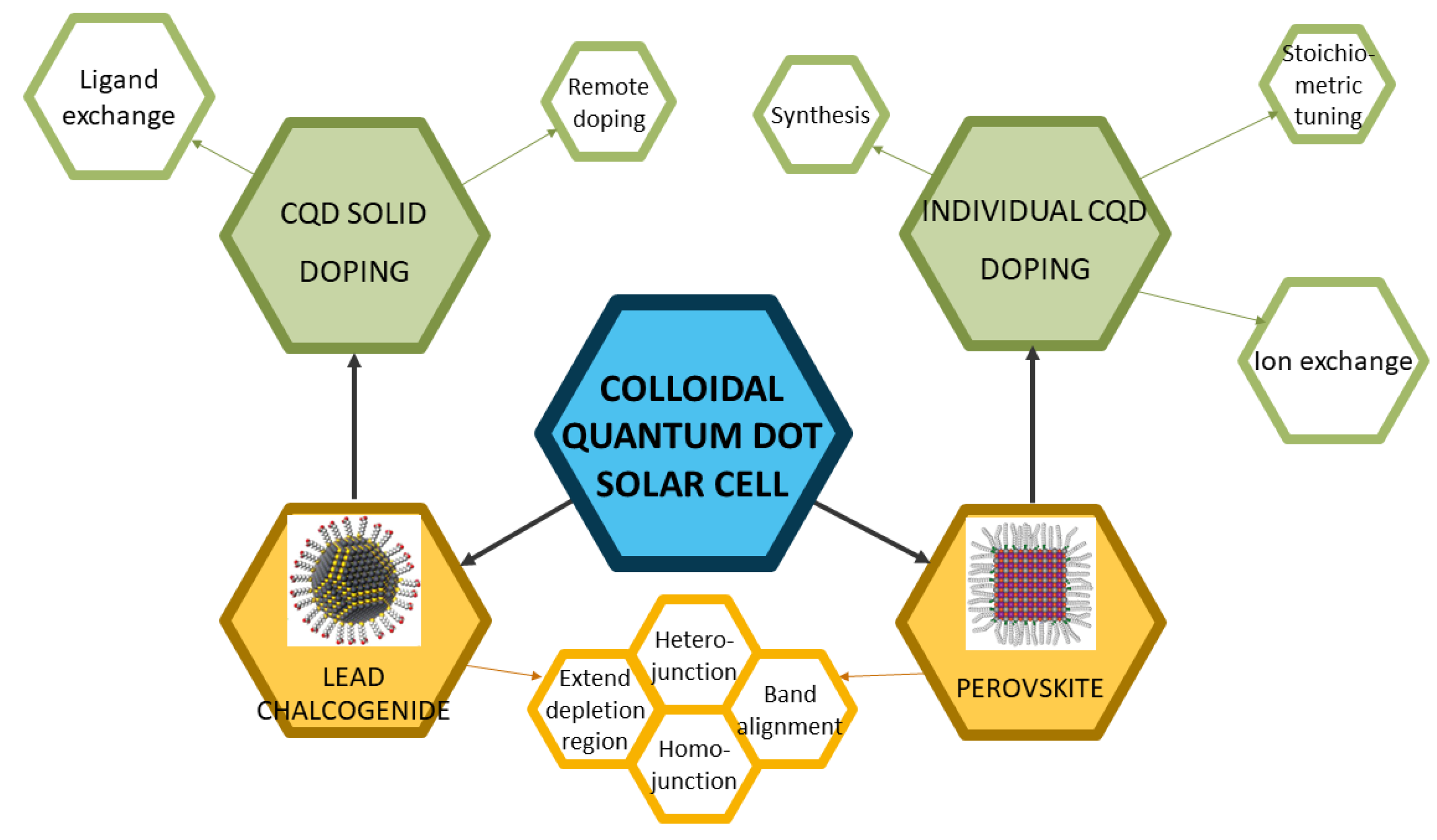
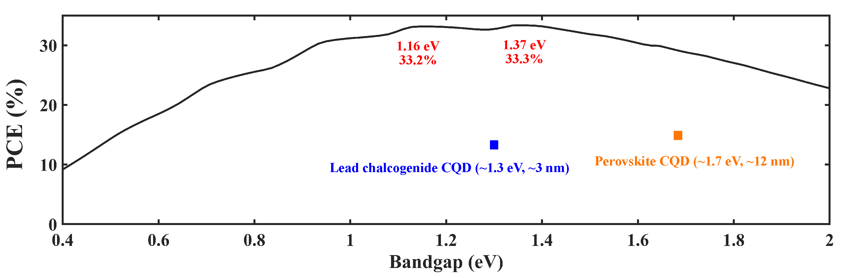


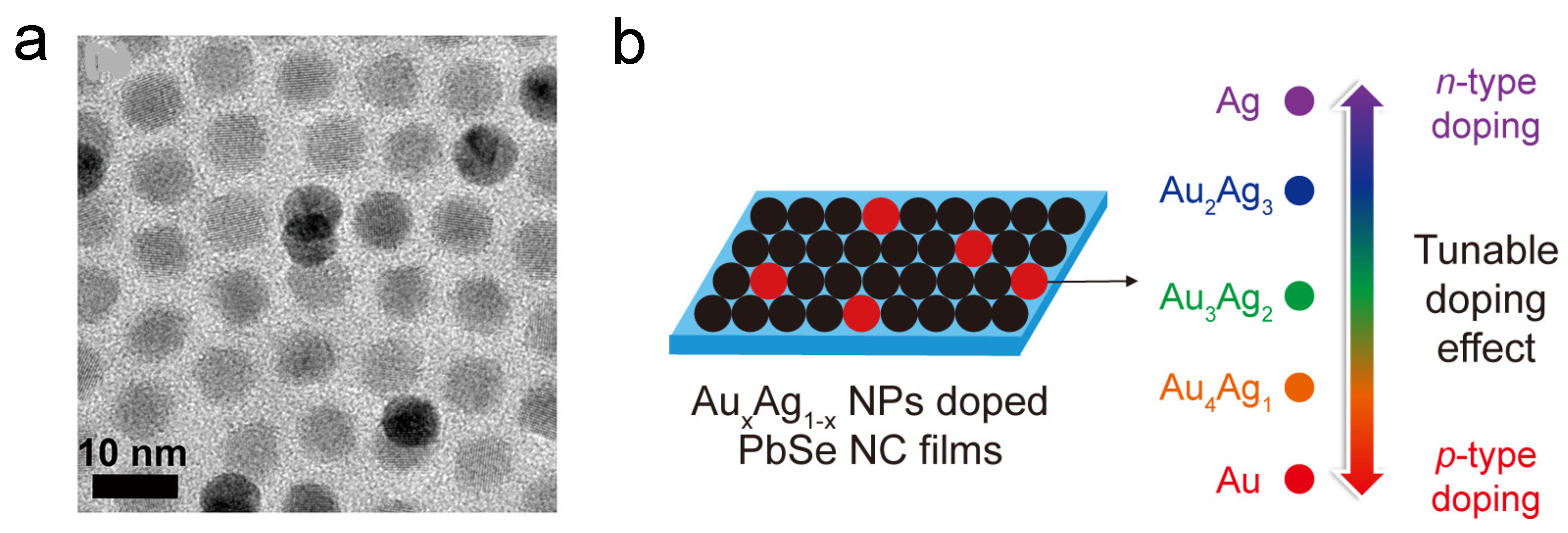
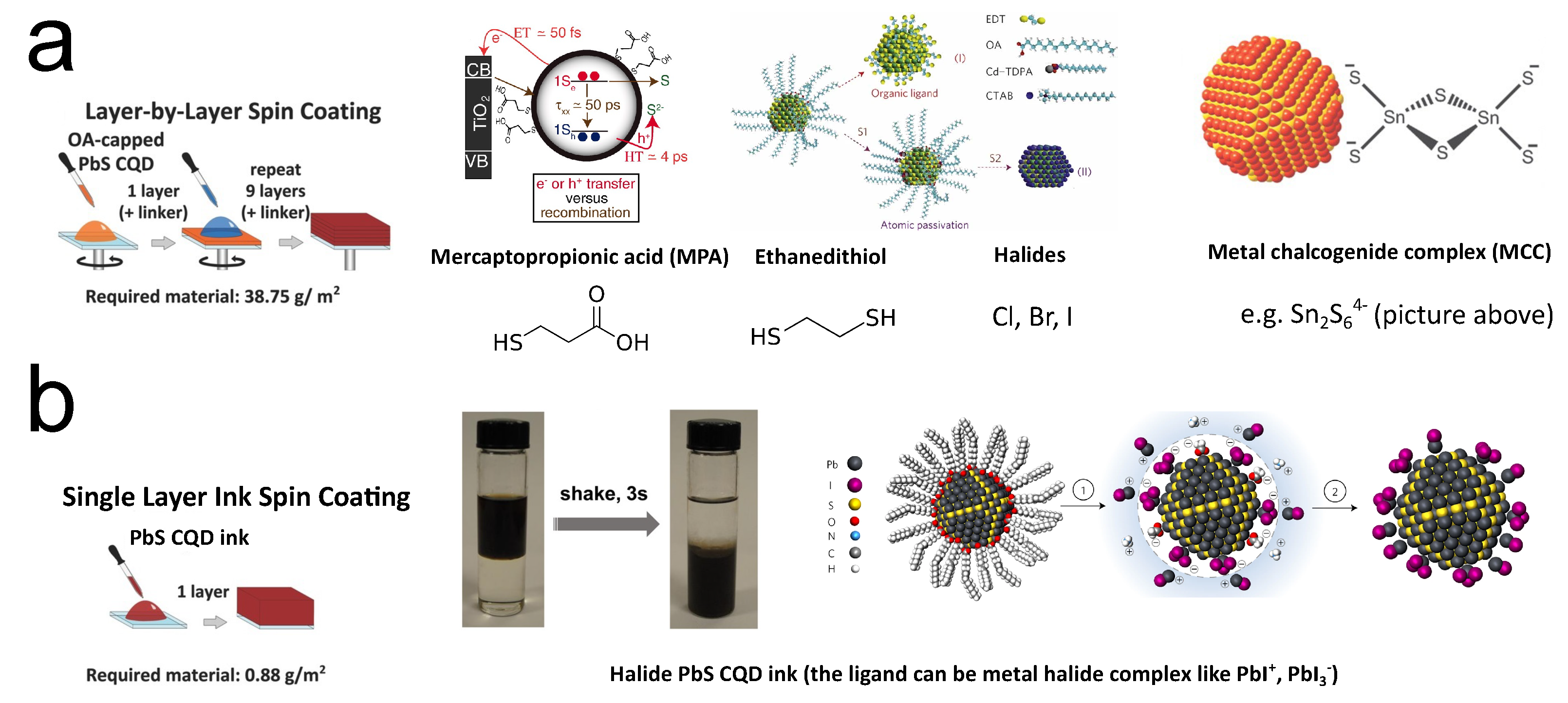

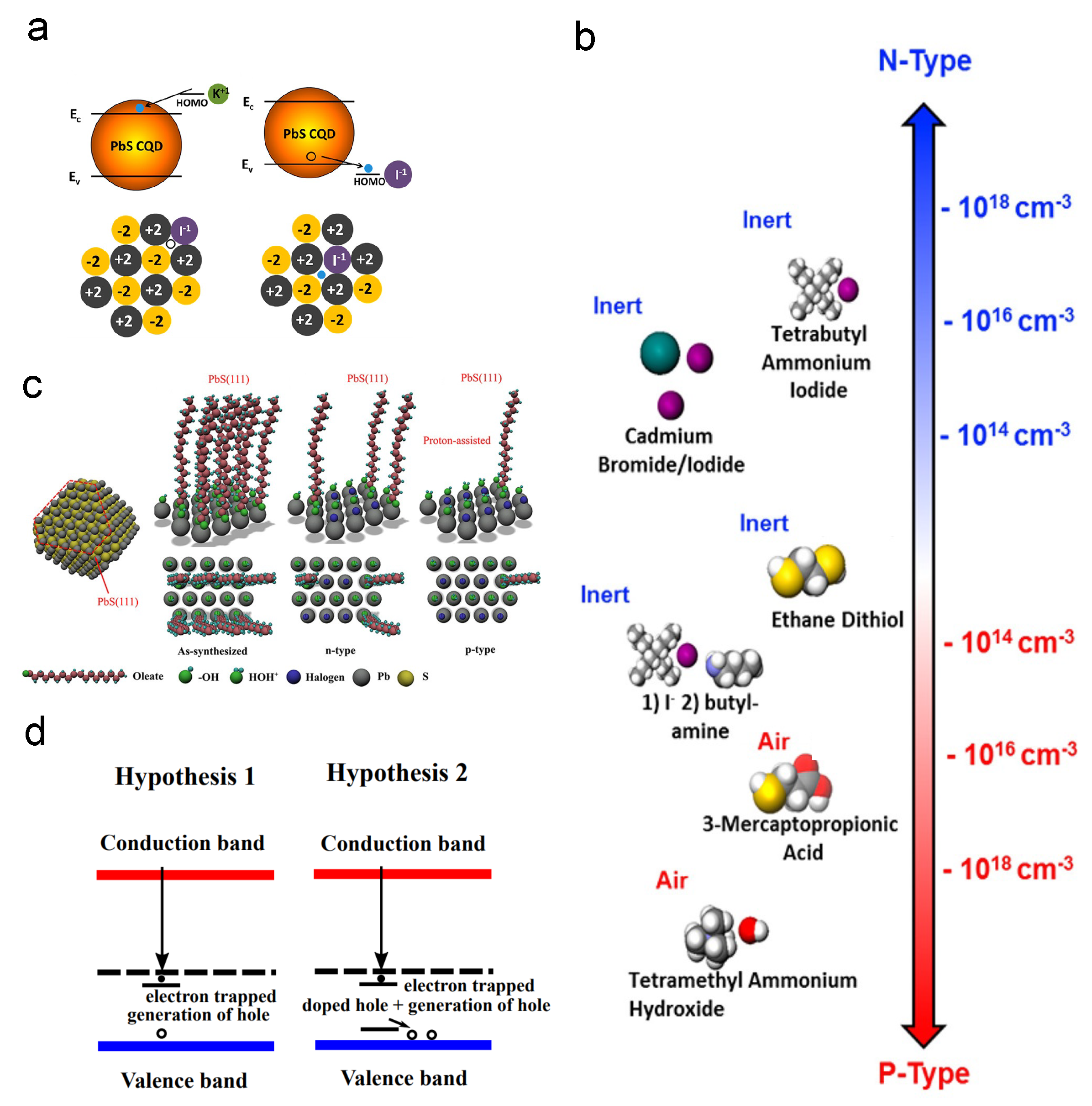
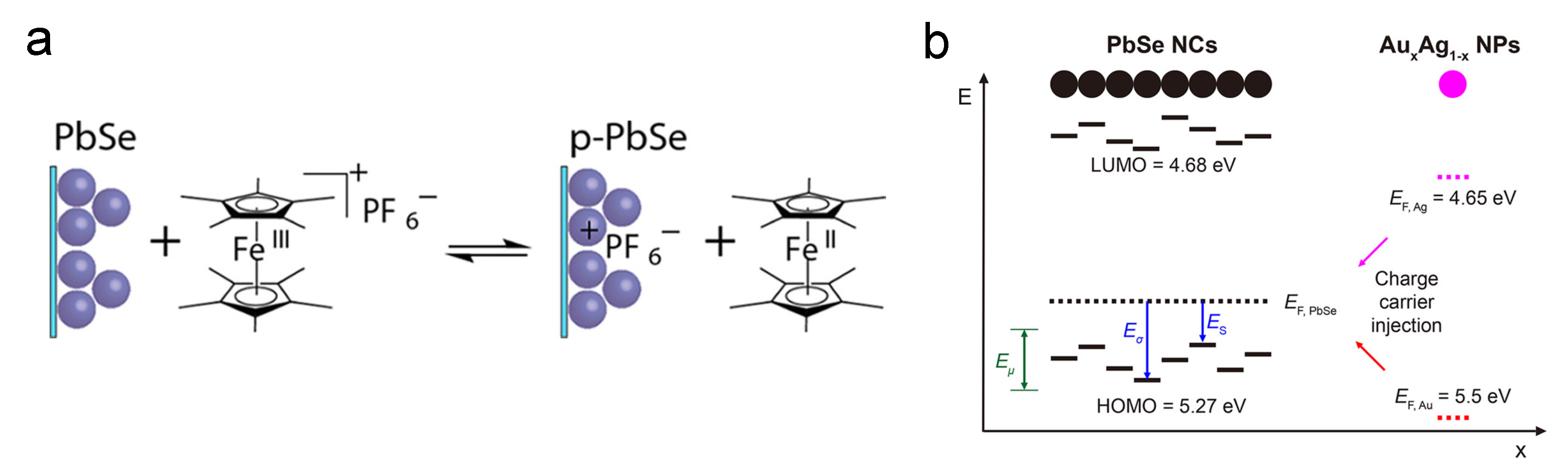

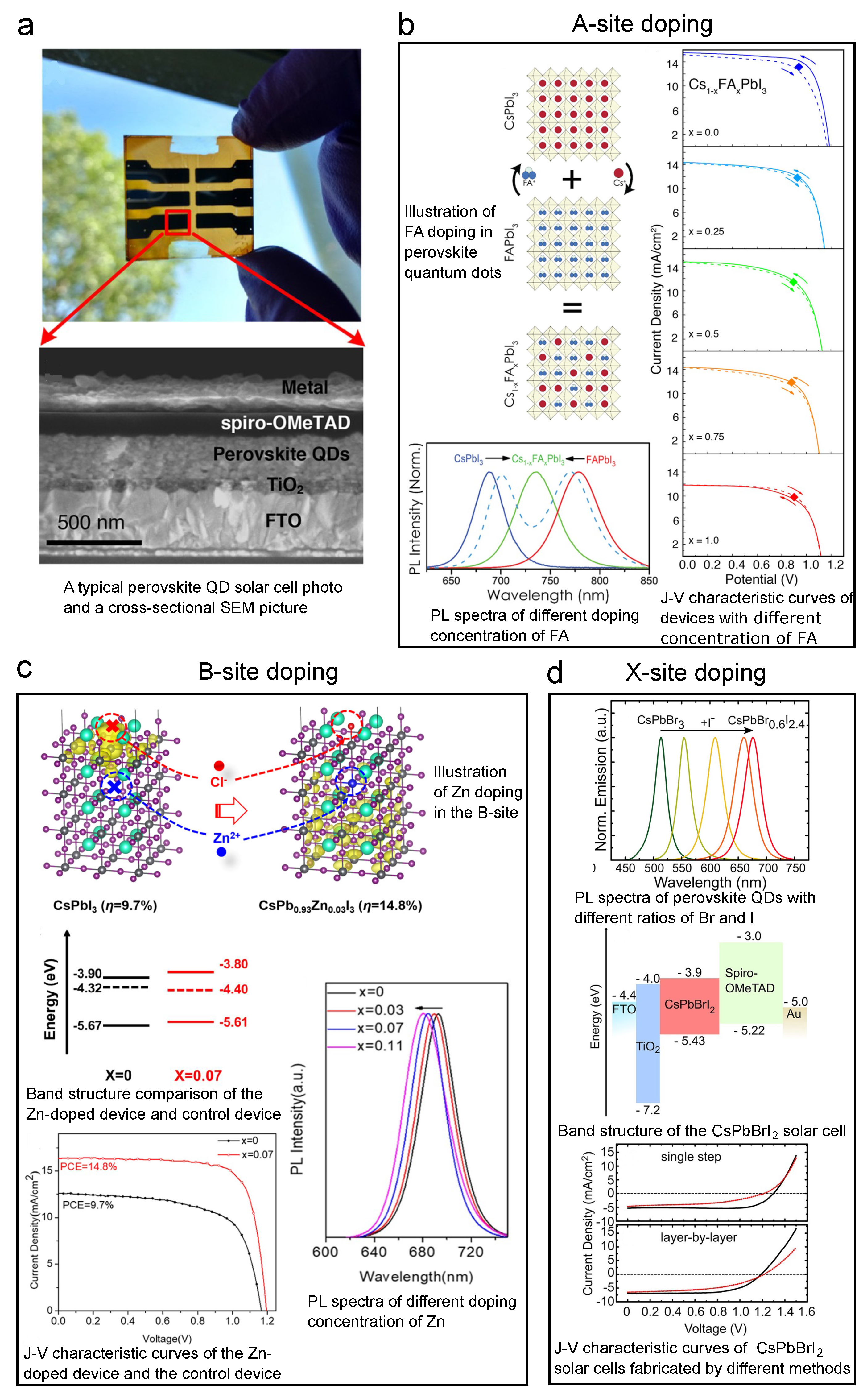

Publisher’s Note: MDPI stays neutral with regard to jurisdictional claims in published maps and institutional affiliations. |
© 2022 by the authors. Licensee MDPI, Basel, Switzerland. This article is an open access article distributed under the terms and conditions of the Creative Commons Attribution (CC BY) license (https://creativecommons.org/licenses/by/4.0/).