Article

Flux-Weakening Drive for IPMSM Based on Model Predictive Control

School of Automation, Northwestern Polytechnical University, 1 Dongxiang Road, Chang’an District, Xi’an 710129, China
*
Author to whom correspondence should be addressed.
Energies 2022, 15(7), 2543; https://doi.org/10.3390/en15072543
Submission received: 25 February 2022 / Revised: 24 March 2022 / Accepted: 29 March 2022 / Published: 30 March 2022
(This article belongs to the Special Issue Design, Analysis and Control of Permanent Magnet Machines)

Abstract

:
This paper presents a flux-weakening model predictive control (FW-MPC) for the interior permanent magnet synchronous motor (IPMSM) drive system. The FW control is a strategy to extend the IPMSM’s operating region. However, the primary FW needs to track the torque reference and maximize the electrical torque per current amplitude with the current and voltage limitations. The two objects make it impossible to solve the FW problem using the optimization method. We proposed an equivalent optimization problem to simplify the complex FW problem, including two objective functions. The MPC is selected as the controller due to its high robustness and transient performance. The constraints from the equivalent optimization problem are added in the MPC to control the IPMSM in the FW region. The simulation and experiment results indicate that the proposed FW-MPC is feasible and effective in driving the IPMSM in the FW region. The proposed FW-MPC can find the optimal point with the maximum electrical torque satisfying the current and voltage limitations. Therefore, the proposed FW-MPC can extend the IPMSM’s operating region, benefiting the IPMSM’s application.

1. Introduction

The interior permanent magnet synchronous motor (IPMSM) is widely applied, due to its advantage over the power density and high efficiency [1,2,3]. However, the maximum current and voltage have limited the maximum torque and speed, which can affect the IPMSM’s power density and application. Hence, many researchers work to solve the flux-weakening (FW) problem of IPMSM to extend the operating region. The IPMSM operating region is shown in Figure 1, and the maximum torque per ampere (MTPA) is an operation to minimize the copper loss of the IPMSM, containing permanent magnet torque and reluctance torque [4,5,6]. Besides, the MTPA has a maximum electrical torque compared to other strategies.
The flux weakening (FW) control based on the MTPA can improve the maximum torque and extend the operating region, i.e., both the MTPA region and the FW region [7,8,9]. The advantage of high speed has an attraction for the applications of a wide speed range, e.g., the electric vehicle, rail transit, and the turbo drive. Additionally, the FW operation can reduce the design difficulty of the IPMSM with limited volume and weight since the FW operation can increase the rotor speed. However, the FW has not been widely applied due to its complexity.
The feedback FW always utilizes the feedback signals (e.g., the feedback currents, the back-EMF, or the dq-voltage commands) to limit the voltage [10,11,12,13]. However, due to the mechanical time delay being far greater than the electrical time delay, the transient performance is not excellent. Nicola Bedetti et al. utilized the feedback voltage regulation to limit the back-EMF within the maximum voltage in the FW region [14]. Yuzheng Chen et al. utilized three complex look-up tables (LUT), a hysteresis regular, and the feedback voltage reference to limit the whole flux, aiming at limiting the back-EMF within the maximum voltage and realizing FW [15]. Silverio Bolognani et al. utilized an adaptive current angle to limit the maximum voltage [16]. However, according to the electrical function, the stator current amplitude (is) is not positively correlated to the electrical torque. Besides, the simulation results in their paper indicate the system is unstable to provide a negative electrical torque. Similarly, with [16], the main flux was controlled to limit voltage [17], which is unstable to track a complex torque reference, i.e., the negative reference.
The feedforward FW control has better dynamic performance, which often utilizes the current or torque. In [18], S. Jung et al. utilized the Ferrari method to solve two quartic equations with three nonlinear systems. Hao Ge et al. utilized the LUTs, optimized offline, to extend the MTPA speed region [9]. Although the LUT is a way to overcome the complex online calculation, the complexity of the calculation is not the main issue with the development of the microprogrammed control unit (MCU). Tae-Suk Kwon et al. proposed a hybrid FW, combined with feedback and feedforward signals, to improve the speed with limited voltage [19]. However, three complex LUTs were utilized to store the current trajectories.
In practice, the FW problem can be regarded as an optimization problem with constraints. Meanwhile, model predictive control (MPC) with constraints is often utilized to solve the optimization problem. Hence, the FW with MPC (FW-MPC) is an intelligent method to solve the FW problem. However, due to the MPC’s complexity, it’s not accessible to implement the MPC for the FW problem. Z. Mynar et al. proposed an MPC strategy for FW control [20]. However, this strategy can’t drive the IPMSM with the optimal states. Although the assumption (Ld ≈ Lq) can linearize the IPMSM model, the optimal point with the maximum torque can’t be obtained. Besides, a constant rotor speed substituted for the real-time speed also results in solid nonlinearity and current ripple. What’s more, the method in [20] needs massive calculation without explicit functions. The common flux-weakening strategy for IPMSM is listed in Table 1.
In this paper, we propose a new FW-MPC to solve the FW problem and drive the IPMSM. In practice, the FW problem has the following two objective functions: tracking the torque reference and maximizing the electrical torque per current amplitude within the current and voltage limitations. We transformed the FW problem into an equivalent optimization problem with a standard form. With the equivalent method, the proposed FW-MPC can improve the IPMSM’s speed and electrical torque. What is more, the simulation and the experiments indicate that the proposed FW-MPC has more advantages for improving the IPMSMs speed and electrical torque in the FW region.

2. IPMSM Model

The IPMSM model is often given in a discrete-time form for the MPC implementation using the forward Euler method. With the discrete-time IPMSM model, the MPC can optimize the control vector, subject to the constraints. The discrete-time IPMSM model is defined as follows:
x i k + 1 = A x i k + B u k + C + W
where,
A = 1 R s T s L d ω e L q T s L d ω e L d T s L q 1 R s T s L q   B = T s L d 0 0 T s L q C = 0 ω e φ f T s L q   u = u d u q x i = i d i q
A, B, and C are the parameter matrices, W is the disturbance parameter matrices, xi is the state vector, and u is the control vector. Let k ∈ N+ identify the discrete-time instant t = kTs. The parameters (Ld, Lq, and φf) can be estimated with the motor design software [2,21]. In practice, the electrical torque function is often defined as follows:
T e = p φ f + Δ L i d i q
where, Δ L = L d L q .
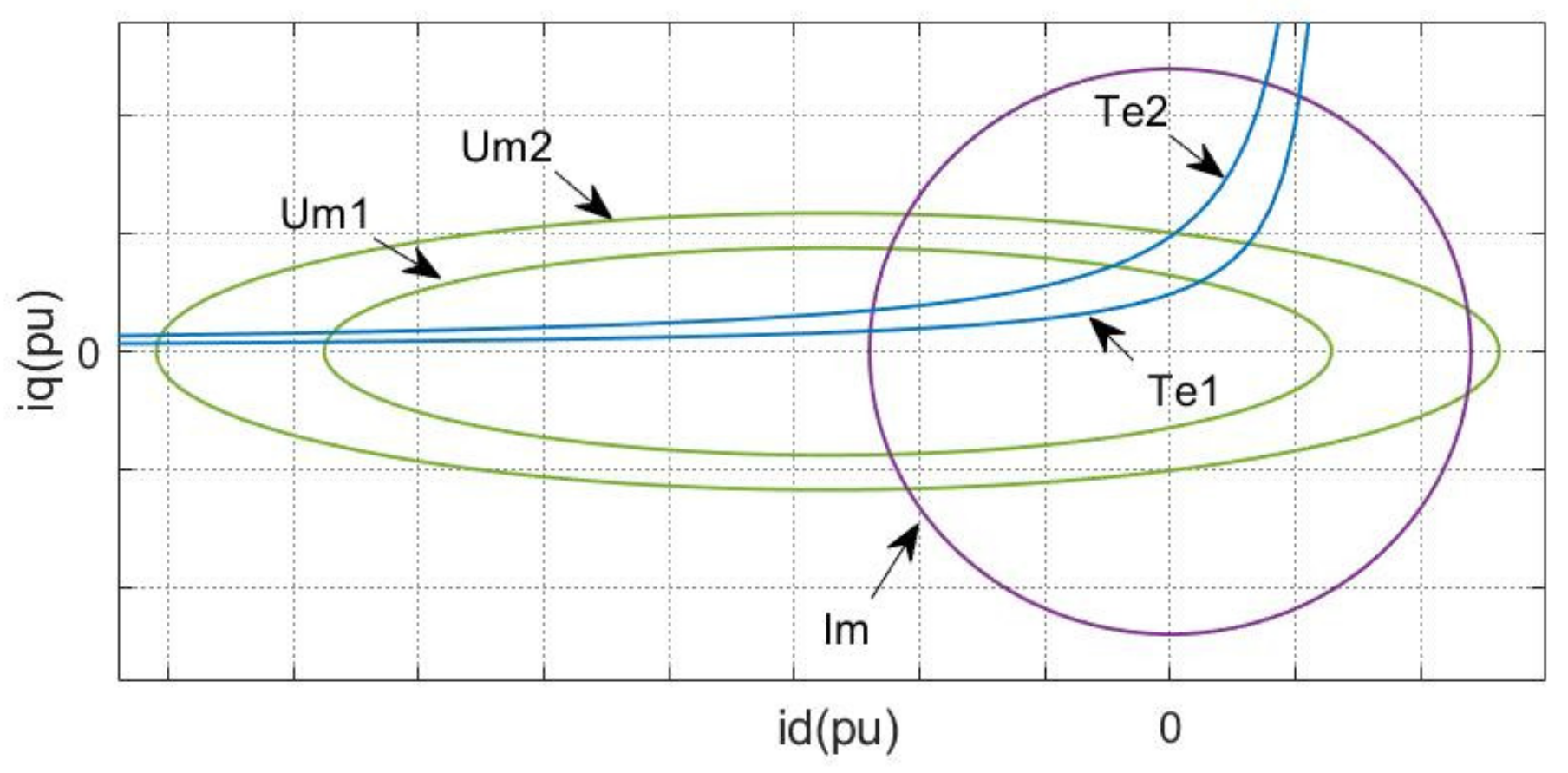
The IPMSM drive system has its own unique feasible domain. The feasible domain is defined by the maximum current (Im) and maximum voltage (Um). The schematic diagram of the constraints (Im and Um) is shown in Figure 2. The current and voltage limitations are defined as follows:
f i : = i d 2 + i q 2 I m 2 0 f U : = u d 2 + u q 2 U m 2 0
where,
u d = R s i d ω e L q i q u q = R s i q + ω e φ f + L d i d
In Figure 2, Um1 and Um2 are the voltage limitations fU (ωe1) and fU (ωe2), ωe1 > ωe2. Im is the current limitation. The feasible domain of the IPMSM system is the intersection of the current and the voltage limitations. As can be seen, the voltage limitation shrinks as speed (ωe) increases. Hence, driving IPMSM within the feasible domain is a complex optimization problem.

3. Control System

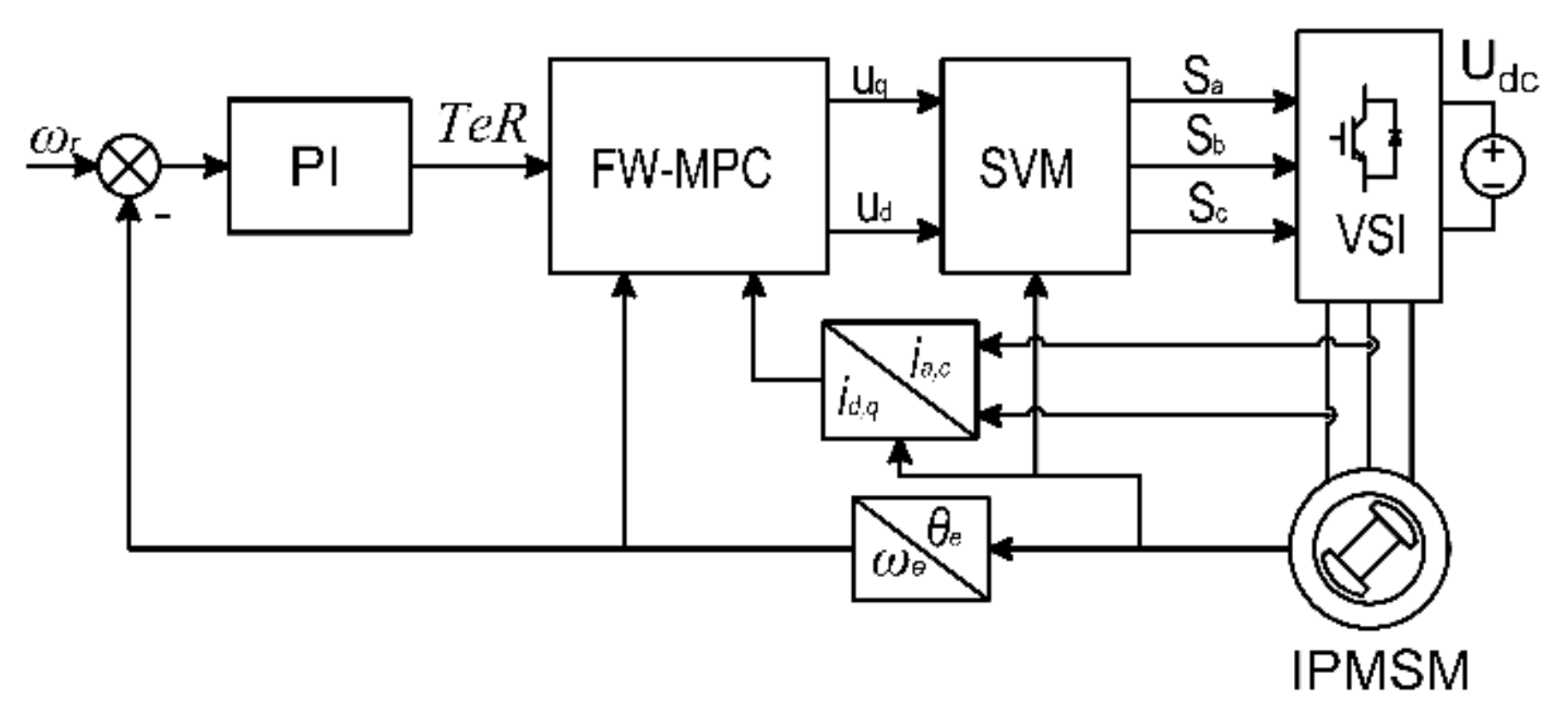
The FW strategy can extend the operating region of IPMSM, which helps adopt IPMSM to different applications. The IPMSM drive system diagram is shown in Figure 3. This paper mainly focuses on the torque loop, which is implemented to track the torque reference. The traditional PI is introduced as the speed controller to implement the experiment [3,22], but it is not the research objective. The FW problem can be given as follows:
m i n :   T e T e R 2
m i n :   x i 2
s . t . :   f i : = i d 2 + i q 2 I m 2 0
f U : = u d 2 + u q 2 U m 2 0

3.1. Equivalent Optimization Problem

Herein, · 2 is the Euclidian norm of a vector, and TeR is the torque reference. The first objective function, defined by Equation (5), is the torque loop’s primary purpose. As can be seen from Figure 2, there are many state points to track the torque reference. Hence, the second objective function, defined by Equation (6), is added to the FW problem to reduce the current. Unfortunately, the FW problem becomes a nonstandard optimization problem with two objective functions, which cannot be solved directly. However, this problem can be transformed into an equivalent optimization problem with a standard optimization form.
As seen from Equation (6), the second objective function is the same as the MTPA problem, which can be given as follows:
m i n :   x i 2
s . t . :   T e T e R = 0
With the optimization process, the MTPA Formulas (11) and (12) can be reached [5,23].
f M T P A : = φ f i d + Δ L i d 2 i q 2 = 0
s . t . : i d 0
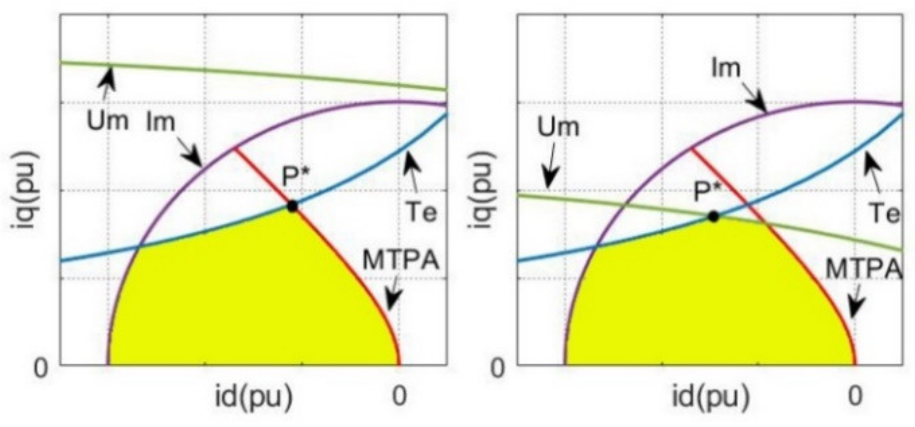
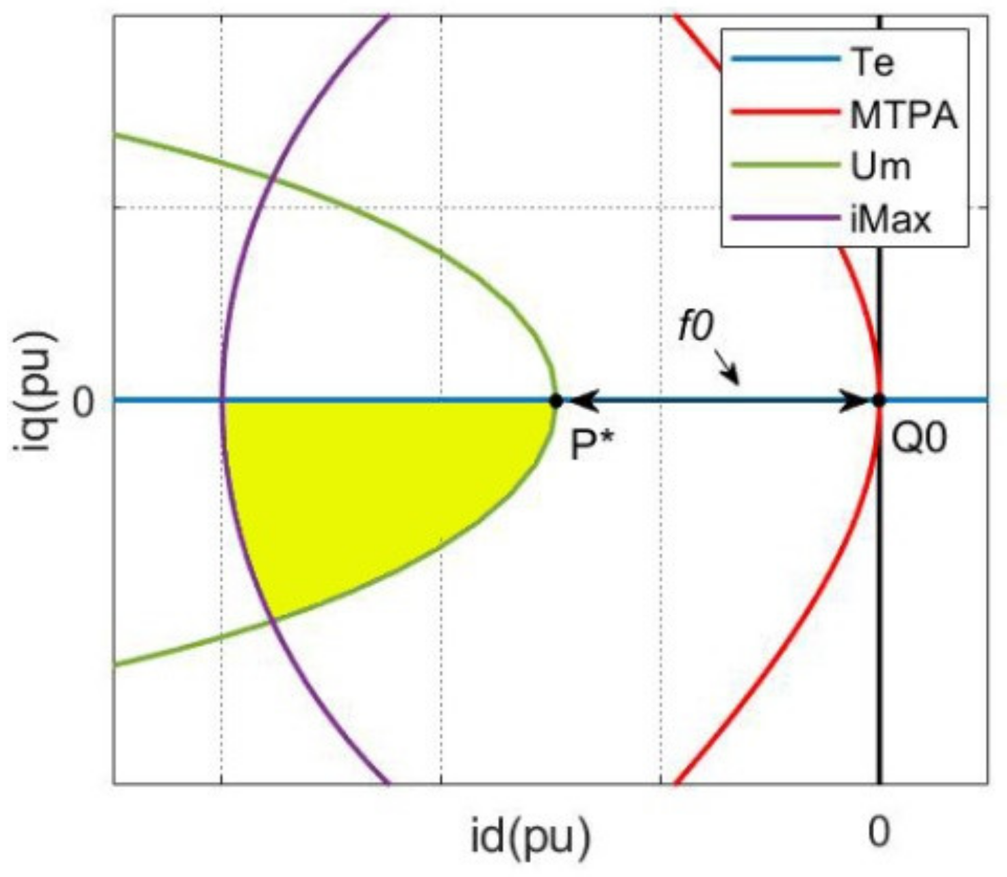
Hence, the optimal point of Equation (6) has the minimum distance to the MTPA trajectory, defined by Equations (11) and (12), along the torque trajectory. Let us assume that the optimal point of the FW problem Equations (5)–(8) is P*, which is drawn in Figure 4. The yellow region is the feasible domain. As seen, Figure 4-Left shows the MTPA problem without voltage limitation, and P* is on the MTPA trajectory. Figure 4-Right shows the FW problem, and P* is the intersection of the electrical torque trajectory and the voltage limitation. Therefore, the whole FW problem has a feasible and unique optimal point.
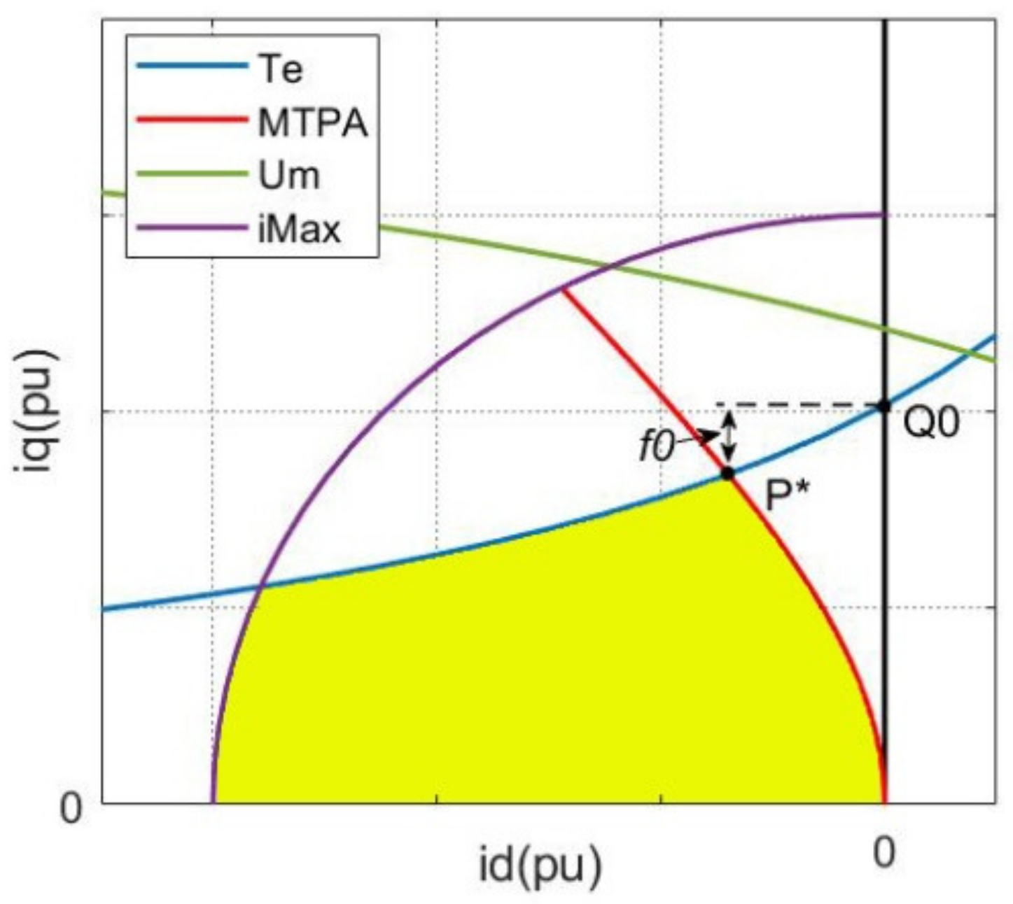
Accordingly, the FW problem can be transformed into finding the optimal point (P*). The FW problem can be divided into the following two conditions: TeR ≠ 0 and TeR = 0. When TeR ≠ 0, we can use the following optimization problem to replace the FW problem equally. The diagram is shown in Figure 5.
m i n :   f 0 = i q i q 0 2
s . t . :   f M T P A = φ f i d + Δ L i d 2 i q 2 0
f i = i d 2 + i q 2 I m 2 0
f i d = i d 0
f U = u d 2 + u q 2 U m 2 0
f T e = s g n T e R T e T e R 0
i q 0 = T e R / p φ f
s g n T e R = 1 , T e R > 0 1 , T e R 0
The point Q0: = XQ0 (iq0, 0) is the torque trajectory and q axis intersection, and the yellow region is the feasible domain. Obviously, Equations (13)–(20) is an equivalent optimization problem for the FW problem Equations (5)–(8), when TeR ≠ 0. If the maximum voltage has limited the optimal point (P*), as in Figure 4-Right, we can obtain the same equivalent optimization problem.
When TeR = 0, we can use the following optimization problem to replace the FW problem equally. The diagram is shown in Figure 6.
m i n :   f 0 : = i d 2
s . t . :   f M T P A : = φ f i d + Δ L i d 2 i q 2 0
f i : = i d 2 + i q 2 I m 2 0
f i d : = i d 0
f U : = u d 2 + u q 2 U m 2 0
f T e : = i q 0
Similarly, the yellow region is the feasible region. The optimization problem Equations (21)–(26) is proposed to find the optimal point (P*), when TeR = 0.

3.2. Proposed FW-MPC Strategy

The proposed FW-MPC (PFW-MPC) strategy contains the equivalent optimization problem, defined by Equations (13)–(26), and the MPC. The whole FW-MPC problem is given as follows:
m i n :     g 0 : = f 0 + Q Δ x i 2 + R Δ u 2
s . t . : h : = x i k A x i f B u k C + W = 0
g 1 : = f M T P A 0
g 2 : = f i 0
g 3 : = f i d 0
g 4 : = f U 0
g 5 : = f T e 0
Herein,
f 0 = i q i q 0 2 , T e R 0 i d 2 , T e R = 0
f T e = s g n T e R T e T e R , T e R 0 i q , T e R = 0
i q 0 = T e R / p φ f
Δ x i = x i k + 1 x i k ,   k 1
Δ u = u k u k 1 ,   k 1
The positive matrix Q and R are the turning parameters of MPC that define the states’ importance; xif is the feedback state variables; W denotes the uncertainty of the system Equation (1). The constraint Equation (28) comes from the discrete-time IPMSM model Equation (1). Let us define the Lagrangian function of the MPC as follows:
L x , λ , μ : = g 0 x + m = 1 5 λ m g m x + m = 1 2 μ m h m x
s . t . :   x = x i T , u T T
λ = λ 1 , λ 2 , , λ 5 T
μ = μ 1 , μ 2 T
Let x* and (λ*, μ*) be any primary and dual optimal point with the zero-duality gap. Since (x*, λ*, μ*) minimizes L(x, λ, μ), the gradient of Equation (39) must vanish at (x*, λ*, μ*).
L x * , λ * , μ * = m a x   λ , μ m i n x   L x , λ , μ
L = g 0 x * + m = 1 5 λ m * g m x * + m = 1 2 μ m h m * x * = 0
s . t . :   h x * = 0
λ m * 0 ,       m = 1 , 2 , , 5
g m x * 0 ,       m = 1 , 2 , , 5
λ m * g m x * = 0 ,       m = 1 , 2 , , 5
Equation (43) is called the duality formula, and Equations (44)–(48) is called the Karush–Kuhn–Tucker (KKT) conditions [24,25]. Then, with the Newton method, we can obtain the optimal point.
x k + 1 = x k + Δ x
λ k + 1 = λ k + Δ λ
μ k + 1 = μ k + Δ μ
where,
Δ x = 2 L + · L
Δ λ = g 1 , , g 5 T
Δ μ = h
Herein, ∇2L is the Hessian matrix of L(x, λ, μ), and ∇2L+ is the Moore–Penrose pseudoinverse matrix of ∇2L. From upper analysis, the proposed strategy needs IPMSM’s parameters. According to [26], the MPC, aiming to track the current, is asymptotically stable despite the system distance. However, the feasible domain will be decreased with the parameter error. Despite the suboptimality of the problem, the proposed strategy has asymptotical stability.

3.3. Classical FW-MPC

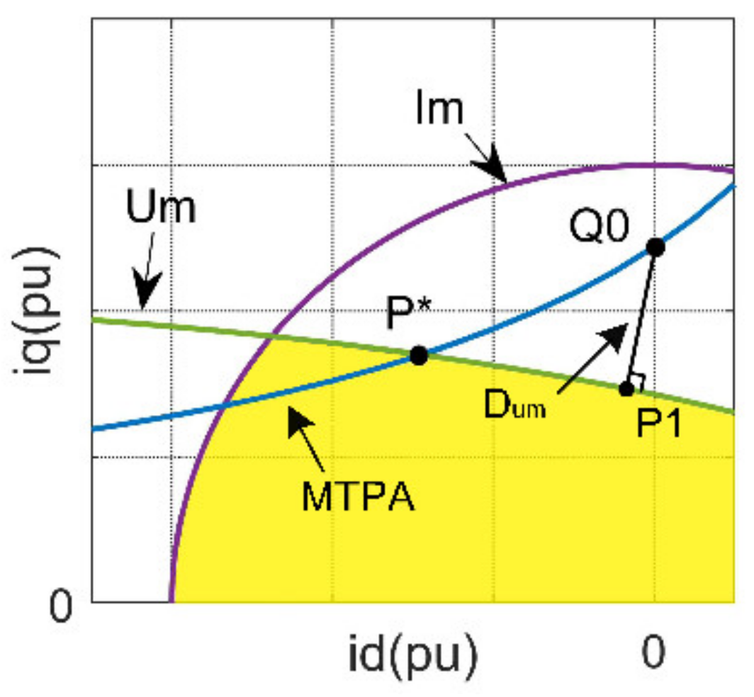
In the classical FW-MPC (CFW-MPC), the voltage limitations are added into the explicit MPC as the constraints. However, the cost function of CFW-MPC is the same as the explicit MPC. Besides, the CFW-MPC often utilizes the multi-parametric toolbox (in MATLAB) and the large-scale optimization tool (e.g., Gurobi version 6.0.0) as the controller, which needs massive calculations [20]. Therefore, CFW-MPC often needs a high-speed controller, e.g., a dual-core i7 processor. Different from CFW-MPC, the PFW-MPC does not need lots of calculations thanks to the equivalent optimization problem, which has a succinct and definitive purpose. The equivalent optimization problem has a single optimal point. However, the CFW-MPC does not take the problem that there are multiple optimal points for the traditional FW problem into account in general. The optimization problem of the CFW-MPC problem can be given as Equations (55)–(58) to compare with PFW-MPC.
m i n :   g 0 : = q i d i d 2 + q i q i q 0 2 + u T R u
s . t . : h : = x i k A x i f B u k C + w = 0
g 2 : = f i 0
g 4 : = f U 0
Herein, R is a symmetrical positive semidefinite, which can reduce the voltage ripple. However, the matrix R can not affect the primary goal. Hence, the primary goal of CFW-MPC is to minimize the distance (Dum) from Q0 to Um, which is shown in Figure 7. As seen, point (P1) is the optimal point of CFW-MPC. Besides, the operating conditions (e.g., speed and torque) are the same as in Figure 4-right. Obviously, the CFW-MPC cannot obtain the optimal point (P*) for the FW control without Equations (9) and (10).

4. Simulation Results

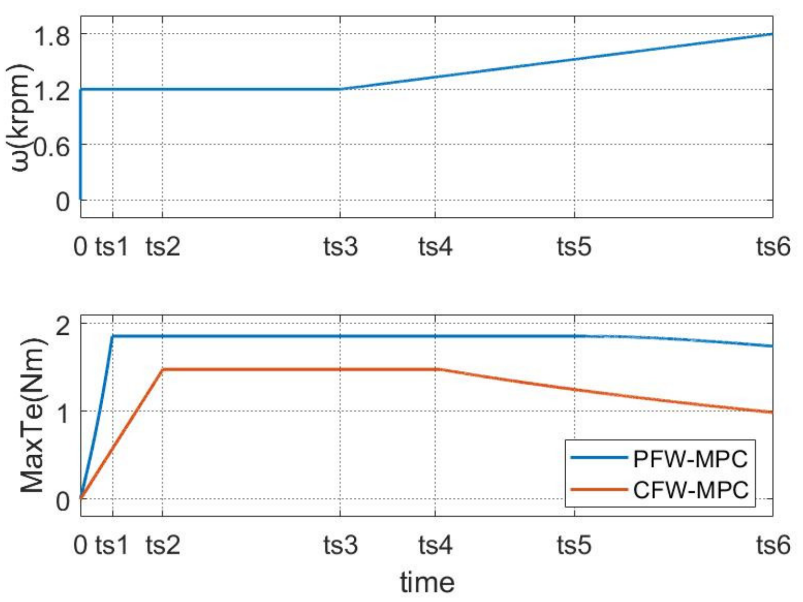
In the upper section, the PFW-MPC strategy with the equivalent optimization is given. The simulations with PFW-MPC and CFW-MPC are implemented to analyze the performance, and the system parameters are shown in Table 2. The simulation results are shown in Figure 8, Figure 9, Figure 10 and Figure 11. The simulation was implemented to maximize the electrical torque at the given speed, as shown in Figure 8. As can be seen, the PFW-MPC has higher electrical torque than the CFW-MPC, especially in the FW region.
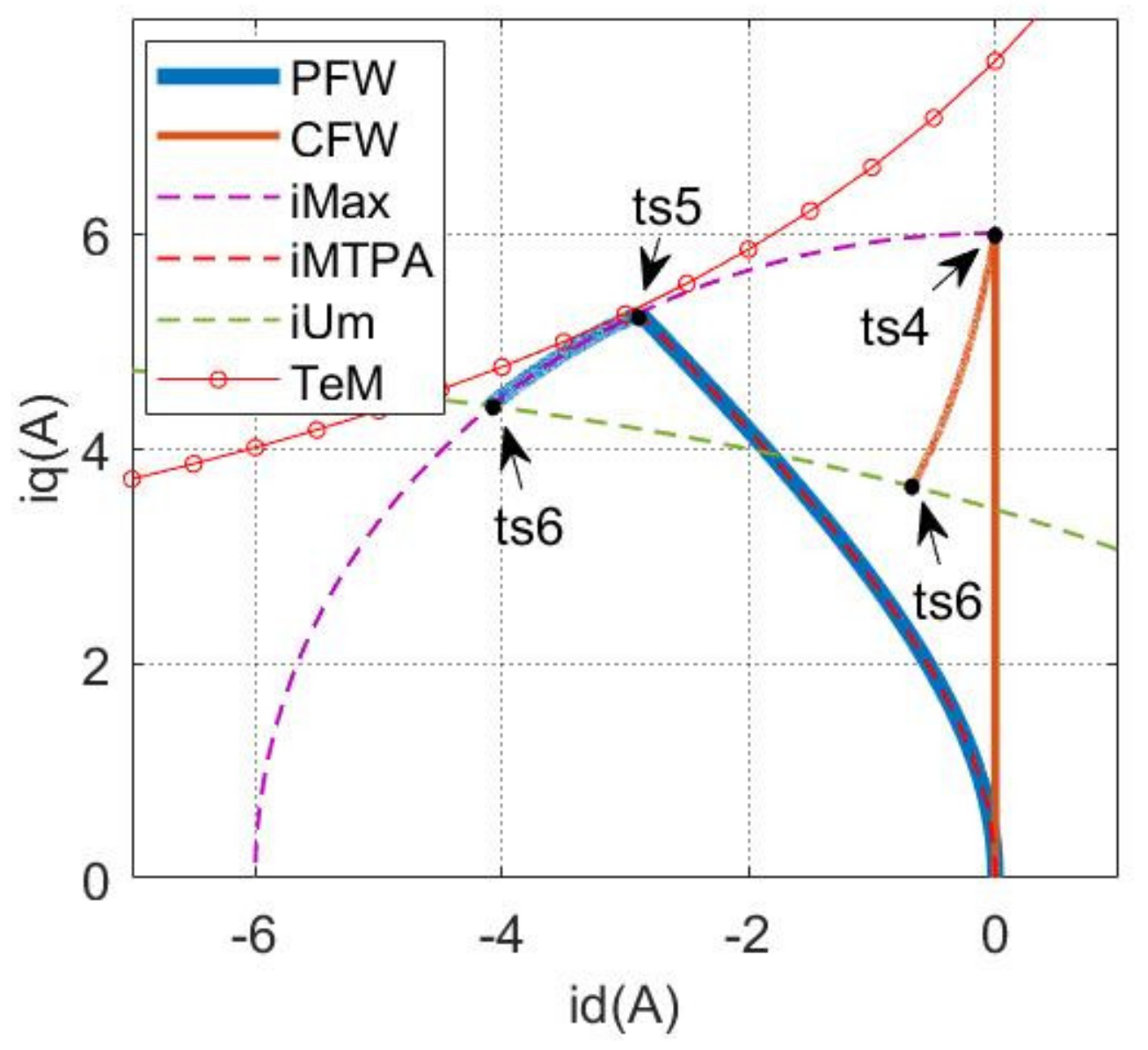
The dq-currents and the input voltages are shown in Figure 9. Besides, the dq-currents are redrawn together to analyze PFW-MPC and CFW-MPC in Figure 10. With the speed increasing (PFW-MPC: ts5–ts6 and CFW-MPC: ts4–ts6), the maximum voltage starts to limit the operating states (id and iq). Obviously, both the PFW-MPC and the CFW-MPC can make the IPMSM operate in the FW region. However, the PFW-MPC has the optimal dq-current because of the equivalent optimization problem Equations (27)–(33). Hence, the PFW-MPC has more advantages in extending the operating region.
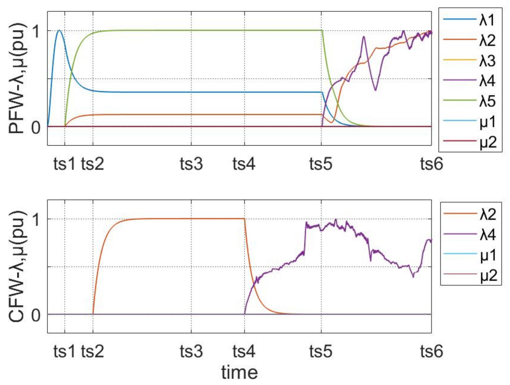
The multipliers (λ and μ) are presented in Figure 11. As can be seen, the PFW-MPC starts to limit the voltage (λ4 > 0) at ts5, later than the CFW-MPC. The simulation results, from Figure 8 to Figure 11, indicate that the PFW-MPC has more advantages in the FW region.

5. Experimental Results

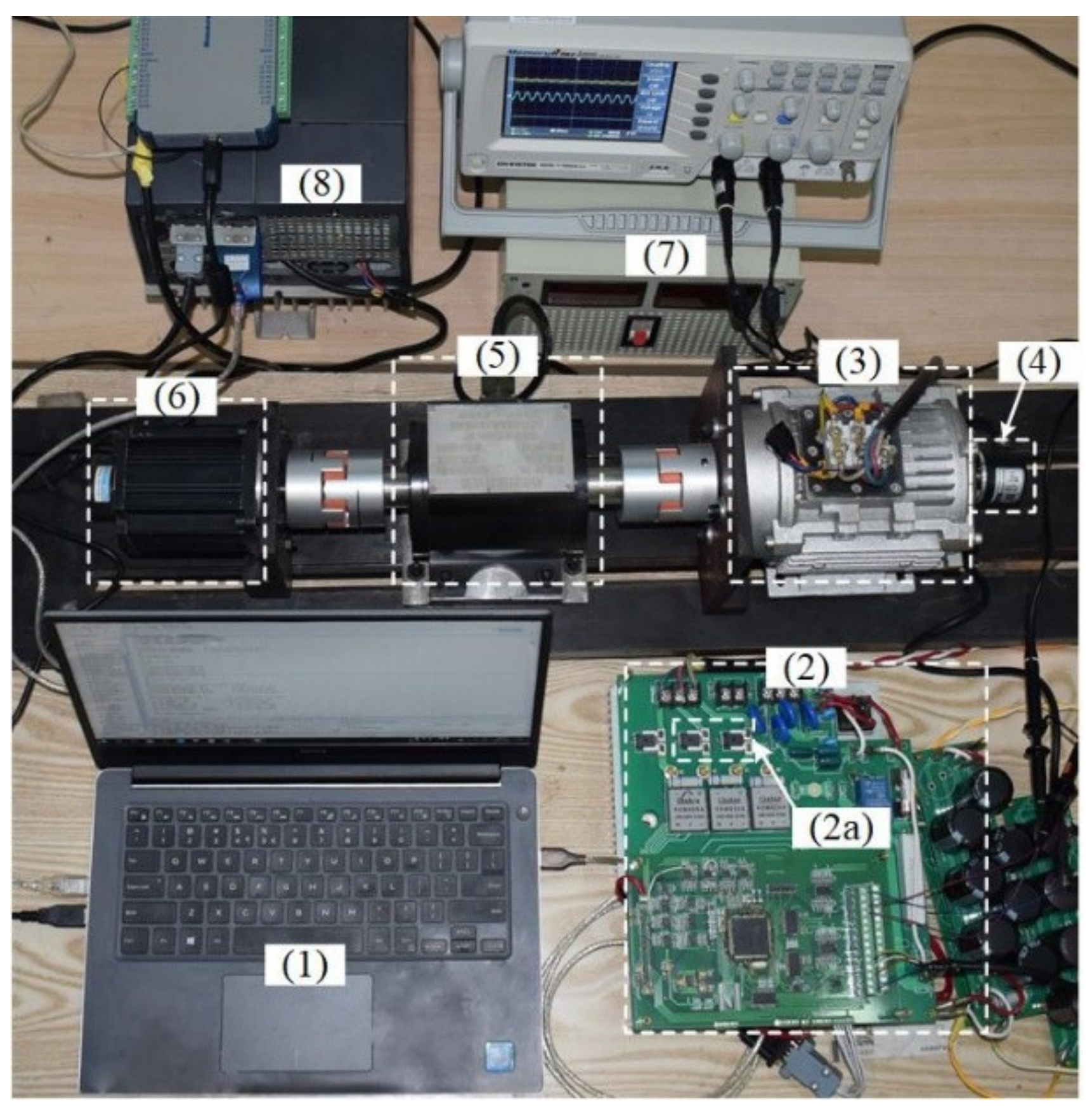
In this paper, an IPMSM, shown in Figure 12, is applied to evaluate the proposed FW-MPC. Besides, the whole experimental platform is presented in Figure 13. The parameters of the experiment system are shown in Table 2. The VSI module is an IPM (PM50RLA060), and the TMS320F28335 was chosen as the control processor, which is widely applied to the IPMSM drive system. The PFW-MPC takes 72 µs, and the CFW-MPC takes 60 us. Both PFW-MPC and CFW-MPC can complete the calculation within a control period. The sensors’ data (including the current sensors and the torque transducer) and the rotor speed were translated to the computer by the serial communication interface (RS485). The servomotor and the servomotor driver can provide the load torque. The driver board, (2) in Figure 13, is implemented to drive the IPMSM, shown in Figure 12.
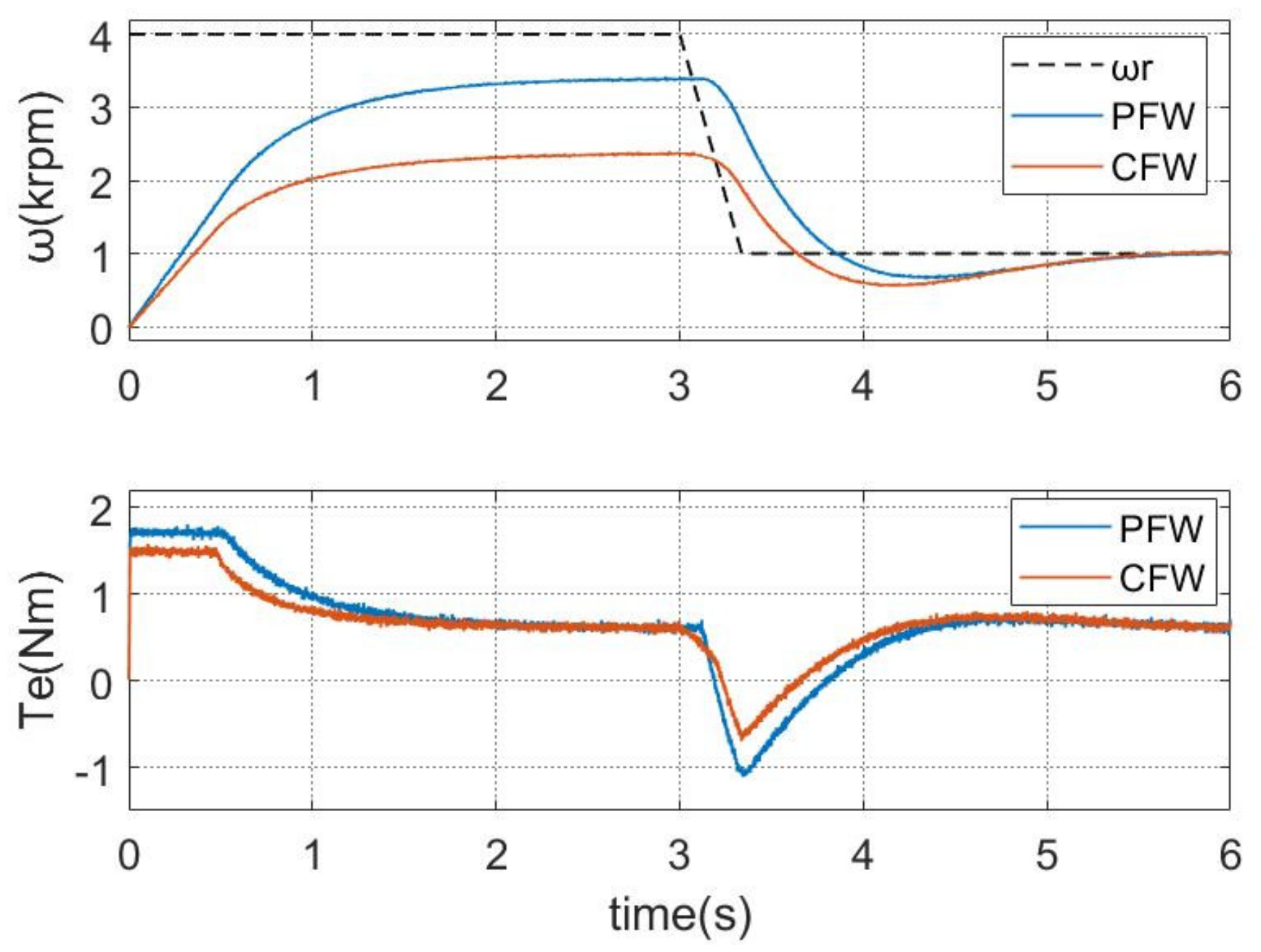
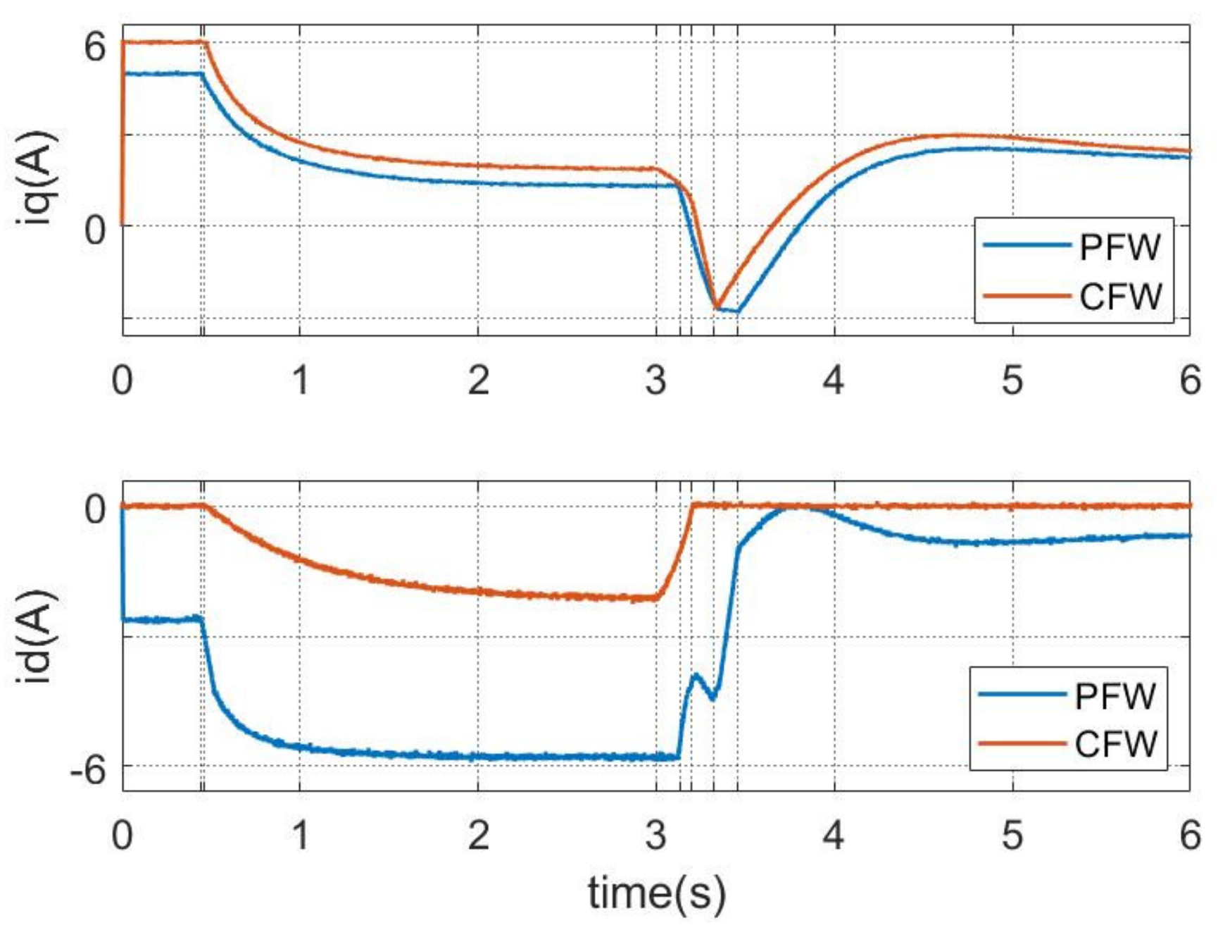
In the experiments, the servomotor was set to provide a load torque (0.6 Nm), and a high-speed reference was given as 4 krpm, which the IPMSM cannot reach with the maximum voltage (70 V), to test the performance of the different strategies in the FW region. In practice, the maximum electrical torque must be limited to protect the mechanical system. Hence, in our experiment, the maximum torque was set at 1.7 Nm. The experiments’ results are presented in Figure 14, Figure 15 and Figure 16. Figure 14 is speed and torque, Figure 15 is IPMSM dq-currents, and Figure 16 presents the current trajectory, drawn in dq-frame.

5.1. Speed and Torque

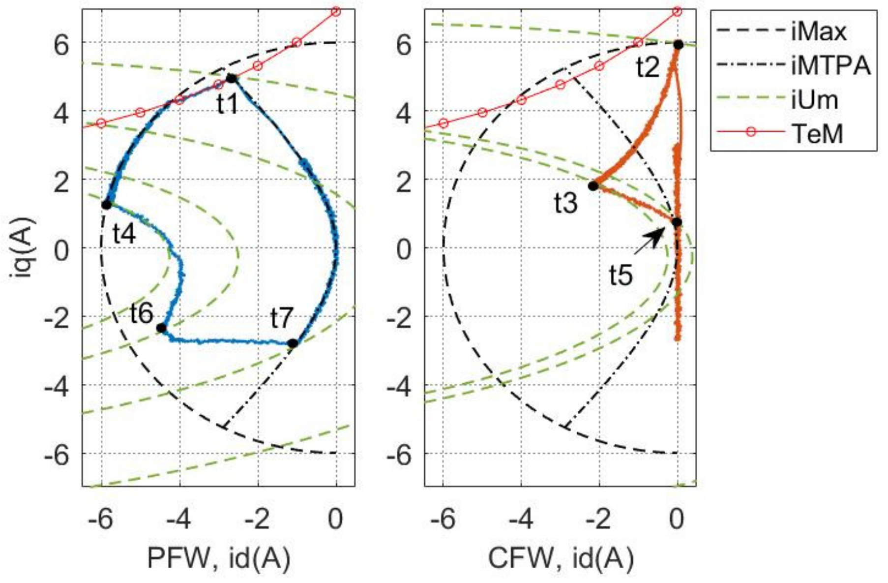
As seen from Figure 14 and Figure 15, the IPMSM operated in the FW region from 0 s to 3 s, both with PFW-MPC and CFW-MPC. However, the PFW-MPC has higher speed and electrical torque than the CFW-MPC. Both the PFW-MPC and the CFW-MPC can operate the IPMSM in the FW region, e.g., PFW-MPC at 3.13 s (t4) and the CFW-MPC at 3 s (t3). However, the PFW-MPC has a higher speed with a higher flux-weakening current (id). Besides, it took more time (about 2 s) to track the speed command in the FW region (high speed) because the maximum voltage can limit the dq-currents and the electrical torque, according to Section 3. However, this result is caused by the IPMSM drive system, e.g., the maximum voltage, the maximum current, and the IPMSM. What is more, the PFW-MPC can provide higher electrical torque than the CFW-MPC because of the equivalent optimization problem.

5.2. Current Trajectory

The current trajectory is used to analyze the operating states of IPMSM. The dq-currents (Figure 15) are redrawn into dq-frames (Figure 16) to analyze the performance. iMax is the maximum current trajectory, iMTPA is the MTPA trajectory, iUm is the current trajectory of fU = 0, and t1–t7 is the time series. Figure 16 indicates that both the PFW-MPC and the CFW-MPC can drive the IPMSM in the FW region, satisfying the maximum current and voltage limitations (iMax and iUm). All iMax, iMTPA, and iUm are considered as the constraints in the PFW-MPC. The PFW-MPC worked in the FW region from t1 to t7, and the CFW-MPC worked in the FW region from t2 to t5. Besides, the electrical torque has been limited to the maximum torque (TeM: 1.7 Nm). However, the PFW-MPC has a more appropriate current state. From the analysis in Section 3, the optimal current point should have the minimum distance to the maximum torque trajectory (TeM in Figure 16). The primary goal of CFW-MPC is to minimize the distance from Q0 to fU = 0. As seen from Figure 16, the experimental trajectories validate the analysis in Section 3. Hence, the PFW-MPC has higher electrical torque, as shown in Figure 14.

6. Conclusions

The FW control can improve the IPMSM’s speed and extend the operating region, which can benefit the IPMSM’s application. In this paper, an equivalent optimization problem is utilized to simplify the complex FW problem, including two objective functions. The constraints from the equivalent problem are added into the MPC, ensuring the IPMSM operating in the FW region and maximizing the electrical torque to control the IPMSM. The simulation and the experiments indicate that the proposed FW-MPC is feasible and effective. What is more, the proposed FW-MPC has more advantages in improving the IPMSM’s speed and electrical torque.

Author Contributions

Conceptualization, Y.Z.; methodology, Y.Z.; software, Y.Z.; validation, Y.Z.; formal analysis, Y.Z.; investigation, Y.Z.; resources, Y.Z.; data curation, Y.Z.; writing—original draft preparation, Y.Z.; writing—review and editing, Y.Z. and R.Q.; visualization, Y.Z.; supervision, Y.Z. All authors have read and agreed to the published version of the manuscript.

Funding

This research received no external funding.

Institutional Review Board Statement

Not applicable.

Informed Consent Statement

Not applicable.

Data Availability Statement

Data is contained within the article.

Conflicts of Interest

The authors declare no conflict of interest.

Nomenclature

id, iqStator dq-axis currents.
ud, uqdq-axis stator voltages.
Ld, Lqdq-axis inductances.
RsStator winding resistance.
TsSampling period.
ωeRotor electrical angular speed.
TeElectrical torque.
φfFlux linkage.
θeRotation angle.
pPole pairs.
A, B, CState parameter matrix
WDisturbance parameter matrix

References

  1. Gu, A.; Guo, Y.; Dong, J.; Ruan, B.; Lian, Y.; Zhang, S.; Song, X. Modeling and Analysis of the Flux-Weakening Range of Interior Permanent Magnet Synchronous Machines with Segmented Permanent Magnets. In Proceedings of the 2020 8th International Conference on Power Electronics Systems and Applications (PESA), Hong Kong, Asia, 7–10 December 2020; Institute of Electrical and Electronics Engineers (IEEE): Piscataway, NJ, USA, 2021. [Google Scholar]
  2. Yamazaki, K.; Kumagai, M.; Ikemi, T.; Ohki, S. A Novel Rotor Design of Interior Permanent-Magnet Synchronous Motors to Cope with Both Maximum Torque and Iron-Loss Reduction. IEEE Trans. Ind. Appl. 2013, 49, 2478–2486. [Google Scholar] [CrossRef]
  3. Dutta, R.; Rahman, M. A Comparative Analysis of Two Test Methods of Measuring d- and q-Axes Inductances of Interior Permanent-Magnet Machine. IEEE Trans. Magn. 2006, 42, 3712–3718. [Google Scholar] [CrossRef]
  4. Inoue, T.; Inoue, Y.; Morimoto, S.; Sanada, M. Maximum Torque Per Ampere Control of a Direct Torque-Controlled PMSM in a Stator Flux Linkage Synchronous Frame. IEEE Trans. Ind. Appl. 2016, 52, 2360–2367. [Google Scholar] [CrossRef]
  5. Preindl, M.; Bolognani, S. Model Predictive Direct Torque Control with Finite Control Set for PMSM Drive Systems, Part 1: Maximum Torque Per Ampere Operation. IEEE Trans. Ind. Inform. 2013, 9, 1912–1921. [Google Scholar] [CrossRef]
  6. Sun, T.; Wang, J.; Chen, X. Maximum Torque Per Ampere (MTPA) Control for Interior Permanent Magnet Synchronous Machine Drives Based on Virtual Signal Injection. IEEE Trans. Power Electron. 2014, 30, 5036–5045. [Google Scholar] [CrossRef]
  7. Ekanayake, S.; Dutta, R.; Rahman, M.F.; Xiao, D. Direct torque and flux control of interior permanent magnet synchronous machine in deep flux-weakening region. IET Electr. Power Appl. 2017, 12, 98–105. [Google Scholar] [CrossRef] [Green Version]
  8. Cheng, B.; Tesch, T.R. Torque Feedforward Control Technique for Permanent-Magnet Synchronous Motors. IEEE Trans. Ind. Electron. 2010, 57, 969–974. [Google Scholar] [CrossRef]
  9. Ge, H.; Miao, Y.; Bilgin, B.; Nahid-Mobarakeh, B.; Emadi, A. Speed Range Extended Maximum Torque Per Ampere Control for PM Drives Considering Inverter and Motor Nonlinearities. IEEE Trans. Power Electron. 2016, 32, 7151–7159. [Google Scholar] [CrossRef]
  10. Ding, D.; Wang, G.; Zhao, N.; Zhang, G.; Xu, D. Enhanced Flux-Weakening Control Method for Reduced DC-Link Capacitance IPMSM Drives. IEEE Trans. Power Electron. 2018, 34, 7788–7799. [Google Scholar] [CrossRef]
  11. Zhang, D.; Zhou, M.; Wang, C.; You, X. A Single Current Regulator Flux-Weakening Control for PMSM under Square-Wave Mode with Wider Operation Range. IEEE Trans. Transp. Electrif. 2021, 8, 1063–1071. [Google Scholar] [CrossRef]
  12. Pellegrino, G.; Armando, E.G.; Guglielmi, P. Direct-Flux Vector Control of IPM Motor Drives in the Maximum Torque Per Voltage Speed Range. IEEE Trans. Ind. Electron. 2011, 59, 3780–3788. [Google Scholar] [CrossRef]
  13. Jang-Mok, K.; Seung-Ki, S. Speed control of interior permanent magnet synchronous motor drive for the flux weakening operation. IEEE Trans. Ind. Appl. 1997, 33, 43–48. [Google Scholar] [CrossRef]
  14. Bedetti, N.; Calligaro, S.; Petrella, R. Analytical Design and Autotuning of Adaptive Flux-Weakening Voltage Regulation Loop in IPMSM Drives with Accurate Torque Regulation. IEEE Trans. Ind. Appl. 2020, 56, 301–313. [Google Scholar] [CrossRef]
  15. Chen, Y.; Huang, X.; Wang, J.; Niu, F.; Zhang, J.; Fang, Y.; Wu, L. Improved Flux-Weakening Control of IPMSMs Based on Torque Feedforward Technique. IEEE Trans. Power Electron. 2018, 33, 10970–10978. [Google Scholar] [CrossRef]
  16. Bolognani, S.; Calligaro, S.; Petrella, R. Adaptive Flux-Weakening Controller for Interior Permanent Magnet Synchronous Motor Drives. IEEE J. Emerg. Sel. Top. Power Electron. 2014, 2, 236–248. [Google Scholar] [CrossRef]
  17. Hoang, K.D.; Aorith, H.K.A. Online Control of IPMSM Drives for Traction Applications Considering Machine Parameter and Inverter Nonlinearities. IEEE Trans. Transp. Electrif. 2015, 1, 312–325. [Google Scholar] [CrossRef] [Green Version]
  18. Jung, S.-Y.; Hong, J.; Nam, K. Current Minimizing Torque Control of the IPMSM Using Ferrari’s Method. IEEE Trans. Power Electron. 2013, 28, 5603–5617. [Google Scholar] [CrossRef]
  19. Kwon, T.; Choi, G.; Kwak, M.; Sul, S. Novel Flux-Weakening Control of an IPMSM for Quasi-Six-Step Operation. IEEE Trans. Ind. Appl. 2008, 44, 1722–1731. [Google Scholar] [CrossRef]
  20. Mynar, Z.; Vesely, L.; Vaclavek, P. PMSM Model Predictive Control With Field-Weakening Implementation. IEEE Trans. Ind. Electron. 2016, 63, 5156–5166. [Google Scholar] [CrossRef]
  21. Xie, W.; Wang, X.; Wang, F.; Xu, W.; Kennel, R.; Gerling, D. Dynamic Loss Minimization of Finite Control Set-Model Predictive Torque Control for Electric Drive System. IEEE Trans. Power Electron. 2015, 31, 849–860. [Google Scholar] [CrossRef]
  22. Zhang, G.; Furusho, J. Speed control of two-inertia system by PI/PID control. IEEE Trans. Ind. Electron. 1999, 47, 603–609. [Google Scholar] [CrossRef]
  23. Consoli, A.; Scelba, G.; Scarcella, G.; Cacciato, M. An Effective Energy-Saving Scalar Control for Industrial IPMSM Drives. IEEE Trans. Ind. Electron. 2012, 60, 3658–3669. [Google Scholar] [CrossRef]
  24. Rawlings, J.B.; Mayne, D.Q.; Diehl, M. Model Predictive Control: Theory, Computation, and Design; Nob Hill Publishing: Madison, WI, USA, 2017. [Google Scholar]
  25. Boyd, S.; Vandenberghe, L. Convex Optimization; Cambridge University Press: Cambridge, UK, 2004. [Google Scholar]
  26. Raković, S.V. Model predictive control: Classical, robust, and stochastic. IEEE Control. Syst. Mag. 2016, 36, 102–105. [Google Scholar]
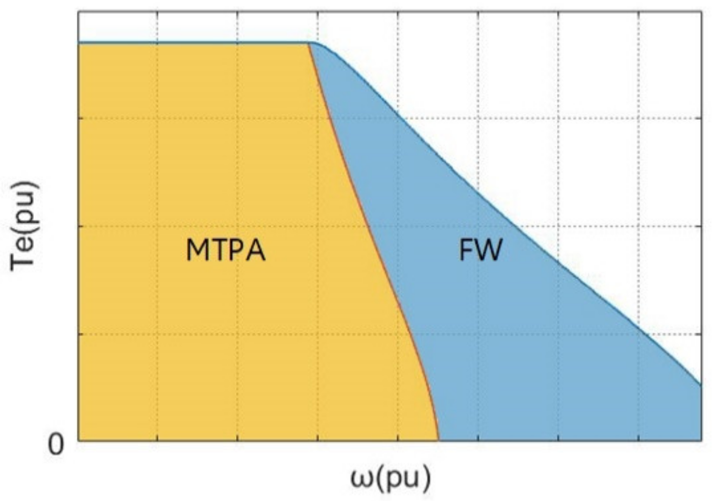
Figure 1. IPMSM operating region.
Energies 15 02543 g001
Figure 2. Feasible domain. Electrical torque: Te2 > Te1, Um1 and Um2: voltage limitations, and Im: maximum current limitation.
Energies 15 02543 g002
Figure 3. IPMSM drive system diagram.
Energies 15 02543 g003
Figure 4. Primal optimization problem for FW. Um: voltage limitation; Im: current limitation; Te: electrical torque trajectory; MTPA: MTPA trajectory.
Energies 15 02543 g004
Figure 5. Equivalent optimization problem, TeR ≠ 0.
Energies 15 02543 g005
Figure 6. Equivalent optimization problem, TeR = 0.
Energies 15 02543 g006
Figure 7. The optimization problem of CFW-MPC. Um: voltage limitation; Im: current limitation; Te: electrical torque trajectory.
Energies 15 02543 g007
Figure 8. Speed and maximum torque. From top to end: given speed and maximum electrical torque.
Energies 15 02543 g008
Figure 9. Current and dq-voltage. From left to right: PFW-MPC and CFW-MPC.
Energies 15 02543 g009
Figure 10. Current trajectories. iMax: maximum current, iMTPA: MTPA trajectory, iUm: current trajectory of fU = 0, and TeM: maximum electrical torque’s trajectory.
Energies 15 02543 g010
Figure 11. Multiplier. λ and μ.
Energies 15 02543 g011
Figure 12. IPMSM. (a): Rotor; (b): Installation diagram. (1) Motor shaft; (2) Permanent magnet; (3) Rotor lamination; (4) Stator winding; (5) IPMSM body.
Energies 15 02543 g012
Figure 13. Experimental platform. (1) Computer; (2) Driver board; (2a) Current sensor; (3) IPMSM; (4) Encoder; (5) Torque sensor; (6) Servomotor; (7) Power source; (8) Servomotor Driver.
Energies 15 02543 g013
Figure 14. Speed and torque.
Energies 15 02543 g014
Figure 15. IPMSM dq-currents.
Energies 15 02543 g015
Figure 16. Current trajectory. Left: PFW-MPC (blue), Right: CFW-MPC (orange). iMax: maximum current, iMTPA: MTPA trajectory, iUm: current trajectory of fU = 0, and TeM: maximum electrical torque’s trajectory. t1: 0.44 s, t2: 0.46 s, t3: 3 s, t4: 3.13 s, t5: 3.2 s, t6: 3.32 s, t7: 3.46 s.
Energies 15 02543 g016
Table 1. Flux-weakening drive for IPMSM.
Strategy
Type
Feedback FWLook-Up TablesFW-MPC
AdvantagesSimpleAlgorithm SimpleOptimal FW
DisadvantagesTime DelayCurrent Ripple;
Need Lots of Data
Complex
Table 2. Parameters.
Udc70 V
Im6 A
Ld9 mH
Lq27.4 mH
Rs0.83 Ω
φf122 mWb
p2
Ts100 µs
Publisher’s Note: MDPI stays neutral with regard to jurisdictional claims in published maps and institutional affiliations.