Article

Gas-Fueled Binary Energy System with Low-Boiling Working Fluid for Enhanced Power Generation

1
Department of Oil and Gas, Saint Petersburg Mining University, 199106 Saint Petersburg, Russia
2
Department of Energy, Saint Petersburg Mining University, 199106 Saint Petersburg, Russia
*
Author to whom correspondence should be addressed.
Energies 2022, 15(7), 2551; https://doi.org/10.3390/en15072551
Submission received: 1 March 2022 / Revised: 20 March 2022 / Accepted: 25 March 2022 / Published: 31 March 2022
(This article belongs to the Special Issue Recent Progress in Bio-Energy with Carbon Capture and Storage)

Abstract

:
This article discusses methods of enhanced power generation using a binary power system with low-boiling fluid as an intermediate energy carrier. The binary power system consists of micro-gas and steam power units and is intended for remote standalone power supply. Trifluotrichloroethane was considered as the working agent of the binary cycle. The developed system was modeled by two parts in MATLAB Simulink and Aspen HYSYS. The model in Aspen HYSYS calculates the energy and material balance of the binary energy system. The model in MATLAB Simulink investigates the operation of power electronics in the energy system for quality power generation. The results of the simulation show that the efficiency of power generation in the range of 100 kW in the developed system with micro-turbine power units reaches 50%.

1. Introduction

Despite the existence of different views on the causes and rates of global climate change, the direct impact of greenhouse gas emissions on the Earth’s weighted average air temperature is undeniable [1,2,3]. The Paris Climate Agreement, adopted in 2015, aims to keep global temperature rise below 2 degrees Celsius and includes measures to reduce greenhouse gas emissions [4]. Furthermore, a significant share of emissions is produced by the energy sector [5,6].
It is an undeniable fact that the share of renewable energy sources, such as wind and solar power plants, will only increase in the near future [7]. However, other types of renewable energy sources should not be neglected. These include, for example, biofuels [8,9], tidal [10,11] and wave energy [12,13], and geothermal energy [14,15].
In addition, the use of fossil fuel power plants will remain important to ensure the stability of the power grid and to cover consumption peaks [16]. In the world today, more than 30 million tons of fossil primary energy sources such as oil, gas, and coal are burned each month to generate electricity. On average, 61% of electricity in the world is obtained from fossil sources [17]. However, the effectiveness of processes for generating energy by burning fossil fuels is not high; for example, the efficiency of combined heat and power (CHP) plants fueled by natural gas in most cases does not exceed 50%. In this regard, the issues of increasing the energy efficiency of generation, conversion, transmission, and distribution of electrical and thermal energy are becoming particularly relevant.
Gas-fired power plants are suitable for supplying power to remote locations where natural gas (NG) is available as the main energy source. The main equipment in such power plants are gas-reciprocating units (GRUs) or gas turbine units (GTUs) [18].
Gas turbines are the units that burn gaseous or liquid fuel to produce gas with high internal energy, driving the shaft of an electric generator [19,20,21]. The advantages of GTU are high reliability, lower noise and vibration level, the possibility of using various types of fuel, short start-up time, and lower emissions, especially of nitrogen oxides [22,23,24]. At the same time, GTUs have a relatively high cost and are difficult to maintain—complete overhaul of the unit cannot be performed on site. These disadvantages have prevented GTUs from replacing GRUs in the power range up to 500 kW [25]. However, in recent years, interest in the use of GTUs operating in this power range has increased again. This has been caused by the trend for the provision of energy-efficient and environmentally friendly power supply in remote regions, where there is not a need for large amounts of generated power [26].

Working Cycles of Power Units for Electric Energy Generation

  • Brayton Cycle
Microturbines (MTs) include turbines with a power rating of tens to hundreds of kilowatts, whereby the upper boundary is rather arbitrary. Some sources take it as 100 kW [27], 300 kW [28,29], 350 kW [30], 400 kW [31], or 500 kW [32,33]. This is the power rating of a single MT but, if necessary, the power output can be increased to several megawatts or tens of megawatts by connecting MTs in parallel [30].
Micro-turbines are divided into single-shaft and twin-shaft designs according to the number of shafts. The single-shaft design improves the MT reliability. In this case, the MT is a unit where a compressor, a turbine, and an electric generator are installed on one shaft. Typically, the gas MT rotational frequency is from 50,000 to 120,000 rpm [24]. In twin-shaft MTs, the compressor is on one shaft with a high-pressure turbine, which is gas-dynamically coupled to a low-pressure turbine, which is on the same shaft as the electric generator.
Natural gas is not the only fuel that can be used for MTs; gases with low methane content (around 30%), e.g., biogas, flare gas, or landfill gas, can also be used, which makes MTs an advantageous solution in distributed generation systems [30].
Gas-fired MTs, operating in the so-called “open cycle”, have widespread application in power engineering [34]. According to this cycle, atmospheric air is fed by a compressor into the combustion chamber, into which fuel is also fed, after which the air, already heated to a temperature of about 950 °C, limited by the heat resistance of the equipment, is supplied to the turbine.
Currently, the electrical efficiency of gas turbines is around 25–35% [32,34,35]. Higher efficiency values usually correspond to gas turbines with higher power output. By comparison, the overall efficiency of gas turbines reaches 80–90% [30].
  • Rankine Cycle
The Rankine cycle and its variation—the organic Rankine cycle (ORC)—are currently widely used in different industries. The high temperature of MT exhaust gases, which is about 250–300 °C, creates opportunities to increase both electric and thermal efficiency of gas-fired MTs by means of an additional circuit, which operates on the basis of the Rankine cycle [36,37]. Steam MTs can be used for this purpose [34]. Low-frequency (3000 rpm) MTs operating on primary or secondary steam with a temperature of about 130–350 °C and pressure of 0.4–3.5 MPa are often used to increase the energy efficiency of boiler-houses and CHP plants. Steam consumption for a 200 kW unit is in the order of 20 t/h [38]. However, in systems with power ratings of several hundred kilowatts, it becomes difficult to ensure acceptable performance using steam as the working medium, and so organic substances are used.
Another example is the gasification of the biomass. Thus, the work [39] demonstrates the efficiency of 49.29% for the power generation process. This value is achieved using biomass gasification to produce synthesis gas, and, consequently, electric power in solid oxide fuel cells and converting thermal energy into power in the ORC.
The type and properties of the low-boiling fluid must be taken into account when designing ORC systems. For example, the paper [40] considers the application of the ORC and steam boiler as a subsystem for recovering waste heat from exhaust gas in a CHP system. The maximum thermal efficiency and exergy efficiency of the CHP were found to be 67.83% and 73.57% for R600, 68.05% and 73.89% for hexane, 68.57% and 74.62% for toluene, 68.59% and 74.65% for cyclohexane, 68.62% and 74.70% for R601, 69.13% and 75.41% for R11, 69.17% and 75.47% for benzene, 69.19% and 75.51% for R123, respectively.
The work [41] presents investigations of the regenerative supercritical Brayton cycle combined with the organic Rankine cycle. The energy source in the proposed cycle is solar energy, which is concentrated in a black object with a heat exchanger heated to 1000 °C. Molten salt passes through the heat exchanger, which then heats the supercritical fluid that rotates the turbine generator. After making work at the expander, the supercritical fluid is cooled by transferring the energy to the low-boiling liquid operating in the Rankine cycle.
According to [42], the ORC can be used in motor vehicles. Heat recovery from the combustion engine allows heating of a low-boiling fluid, which can rotate the shaft of an engine or an electric generator.
A scheme for generating thermal and electric power by means of a turbine operating in the Rankine cycle is shown in Figure 1.
As can be seen from the scheme in Figure 1, after the turbine work between points 1 and 2 is done, which is converted into electric energy at the generator, then between points 2 and 3 thermal energy is taken away from the water steam, with the steam condensing into water. For further utilization of energy q, the ORC can be applied.
The working medium entering the SB (Figure 1) is heated in it to the temperature of steam formation—Sections 4 and 5 of the diagram. Then, steam is generated in the SB at constant pressure (isobar Sections 5 and 6) and superheated steam is produced in the steam superheater (isobar 6–1). Superheated steam, the state of which corresponds to point 1, enters the steam turbine T, where its adiabatic expansion takes place (adiabat 1–2). The kinetic energy of the steam flow is used to rotate the rotor of the steam turbine, which drives the electric generator, GEN. The exhaust steam enters the condenser, C, where it is condensed in contact with the tubes, through which the coolant flows. The generated condensate is transported by pump 7 to boiler SB. Area 1–2–3–4–5–6 in the TS-diagram corresponds to the quantity of heat Q supplied in the cycle, and area 2–3–8–7 is equivalent to the quantity of removed heat q. The shaded area 1–2–3–4–5–6 is equal to the amount of heat converted into work.
The boundary 7–8 and the amount of thermal energy q in Figure 1 depend on the minimum temperature to which the organic fluid can be cooled. The application of the ORC improves the energy efficiency of the CHP system: previous research [36] showed the electricity production increased by 30% and the electric efficiency reached 40%.
  • Allam Cycle
In paper [43], Rodney Allam and his colleagues presented the scientific justification and results of a demonstration plant test for the new energy generation cycle that bears his name. The oxygen-fuel energy cycle, using CO2 as the working medium and hydrocarbon gas as the fuel, allows capturing up to 100% of emissions into the atmosphere, including almost all CO2 emissions, and generating electricity, which is competitive with the existing industrial power generation systems. In addition, the technology does not require any additional CO2 capture equipment. The Allam cycle achieves this through a semi-closed Brayton cycle with high pressure recuperation, using supercritical CO2 as the working fluid. This significantly reduces the energy loss compared to steam and air-based cycles. Furthermore, the fact that the system uses only one turbine with moderate dimensions and requires fewer components than conventional hydrocarbon-fueled systems can also be seen as an advantage.
A modified Allam cycle (Allam-Z cycle) with a simplified mixing system of NG/O2 combustion products and a further circulation of CO2 as the working medium for high efficiency and zero CO2 emissions was proposed and investigated in work [44]. The essence of the modification is that all working media in liquid state are pressurized by pumps instead of compressors, whereas cold energy of liquefied oxygen and liquefied natural gas (LNG) is used for water separation and CO2 liquefaction, and a set of regenerative heat exchangers for heat recovery are installed at the turbine outlet. The paper presents investigations on the influence of turbine parameters on the cycle characteristics. The comparison results presented in the article show that the power output and equivalent net efficiency of Allam-Z cycles are 2.15–2.96% higher than that of the Allam cycle.
Thus, the relevant task is to determine the optimum process parameters for a binary energy system with gas and steam micro-turbines operating in a combined Brayton-organic Rankine cycle. According to the research mentioned above, this article focuses on possibilities for improving the efficiency of CHP generation processes in energy systems with turbine units up to 500 kW.

2. Methodology of the Research

2.1. Object of the Research

Thus study investigated a binary energy system consisting of a main power unit (MPU), which is a micro-gas turbine, and an auxiliary power unit (APU), which is a micro-steam turbine. The working mode of this system is a combination of Brayton and organic Rankine cycles. Previous investigations considered application of pentafluoropropane (C3H3F5) as a low-boiling organic substance. The choice of this medium was due to the power level of the energy system, which was around 1 MW. The present paper discusses the application of trifluotrichloroethane (C2F3Cl3) as the working medium in the ORC due to the lower range of required power. The considered rating for micro-turbine units in the present investigation was up to 100 kW, which is in the power range for this type of unit according to reviewed works. The main physical and thermal properties of the trifluotrichloroethane (Refrigerant R113) are given in Table 1.
The operational scheme of the investigated binary energy system is shown in Figure 2.

2.2. Methods of the Research

The developed energy system was simulated in MATLAB Simulink and Aspen HYSYS software [45,46,47]. Different low-boiling fluids, depending on available pressure and temperature, can be used as working agents of the binary cycle [48,49]. The binary energy system can also produce heat or cold energy. Depending on the residual energy potential of the MPU exhaust gases, either high- or low-grade heat can be generated (with subsequent possible cold energy production). Energy conversion is performed with regard to the energy requirements of the consumers.

2.2.1. Simulation in Aspen HYSYS

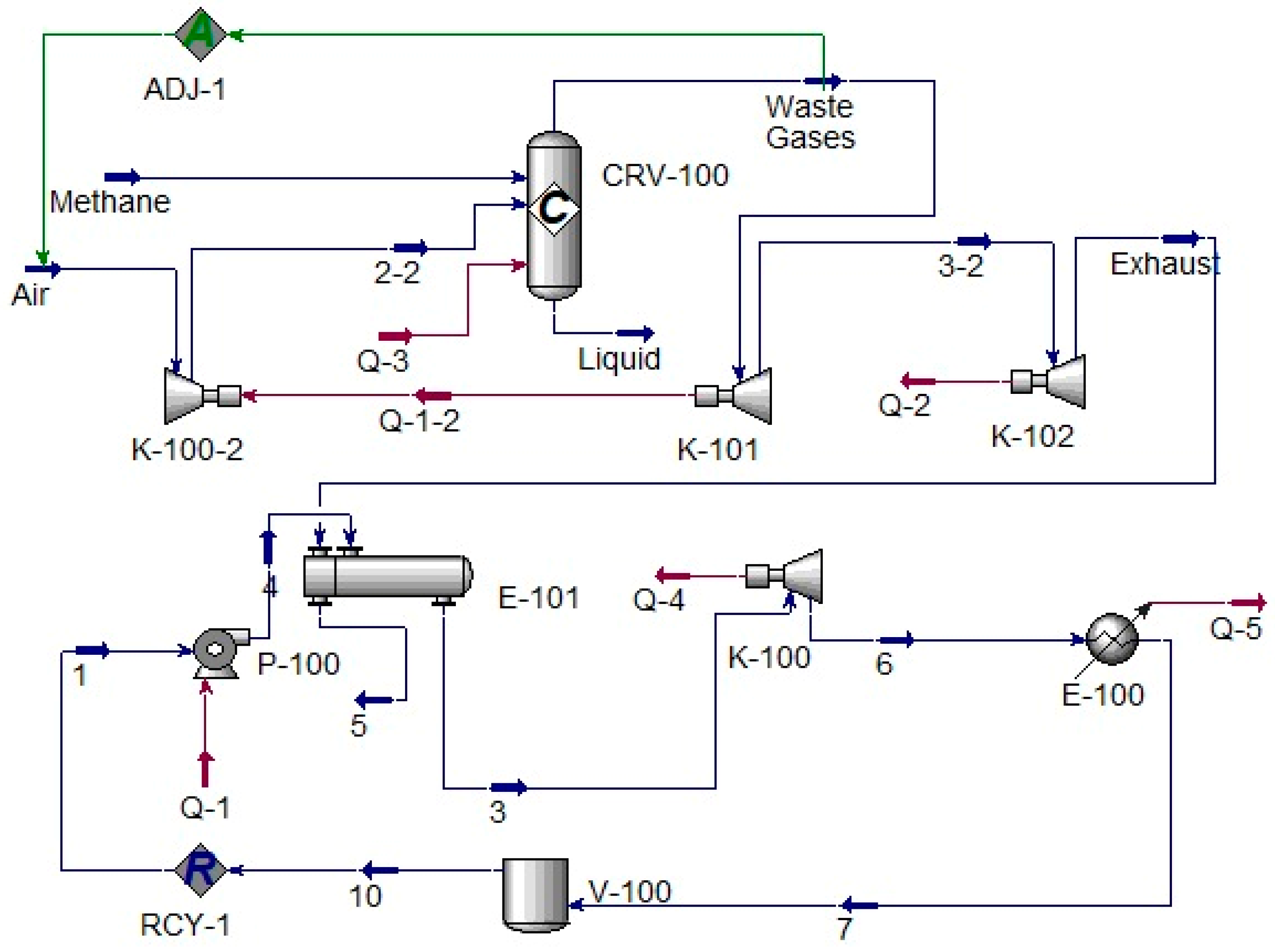
The energy and material balance of the binary energy system was calculated with Aspen HYSYS. The simulation model of the system is shown in Figure 3.
The technological model uses the energy of the working fluid compressed in the centrifugal pump to generate power by the expander. The liquid low-boiling medium from the flow (1) is fed to a centrifugal pump (P-100), which compresses the liquid to 7 MPa. Part of the flow is then evaporated in an atmospheric heat exchanger (E-101) and sent for expansion to an expander (K-100). The expansion energy is used at the pump and the low-pressure gas is fed back to the boost tank. The air stream with the preset composition is supplied to the K-100-2 compressor, where the pressure is increased. The remaining liquid refrigerant is evaporated in a combustion chamber (CRV-100), which is a reactor with 90% methane conversion and an outlet temperature of 950 °C. Gasification takes place due to thermal inflows through the non-insulated walls of the vessels. From the combustion chamber, the stream of heated gases flows into the expander K-101 working on one shaft with the compressor K-100-2. The process is divided into two stages. The first (K-101) uses energy to compress air in the K-100-2, and the second (K-102) generates electric energy. Heated evaporated refrigerant is supplied to the input of the steam turbine and then, after power generation, to evaporators E-101. There, the vapors are condensed and cooled, giving up the heat to the gas stream. The cooling process is also divided into two stages: pre-cooling in E-100 and condensation in V-100 vessel. The refrigerant is then pressurized by the circulation pump and fed back to the heaters.

2.2.2. Simulation in MATLAB Simulink

To investigate electric energy generation processes using a binary system with gas and steam turbines, modeling was carried out in MATLAB Simulink. Furthermore, due to quite different characteristics of the MPU and APU (rotational frequency, voltage, current values, etc.), synchronization of the working parameters of their generators should be carried out.
The mathematical model of a single-shaft gas turbine developed by Rowen in 1983 has three control circuits: temperature, rotational frequency, and acceleration [50]. This model in its classical or upgraded form is widely used in simulation of power systems with gas turbines. The structure of this gas turbine simulation model in MATLAB Simulink is shown in Figure 4.
Steam Turbine and Governor, a standard Simscape library block of MATLAB Simulink, was used as a steam turbine unit [52,53]. Simulation modeling of the energy system operation was carried out stage by stage. Thus, the first system includes a model of the gas turbine, and models of a 30 kW permanent magnet synchronous generator with control system, a passive rectifier with LC-filter, a stabilizing pulse width converter, and the load model in the DC link.

3. Results

3.1. Results of Simulation in Aspen HYSYS

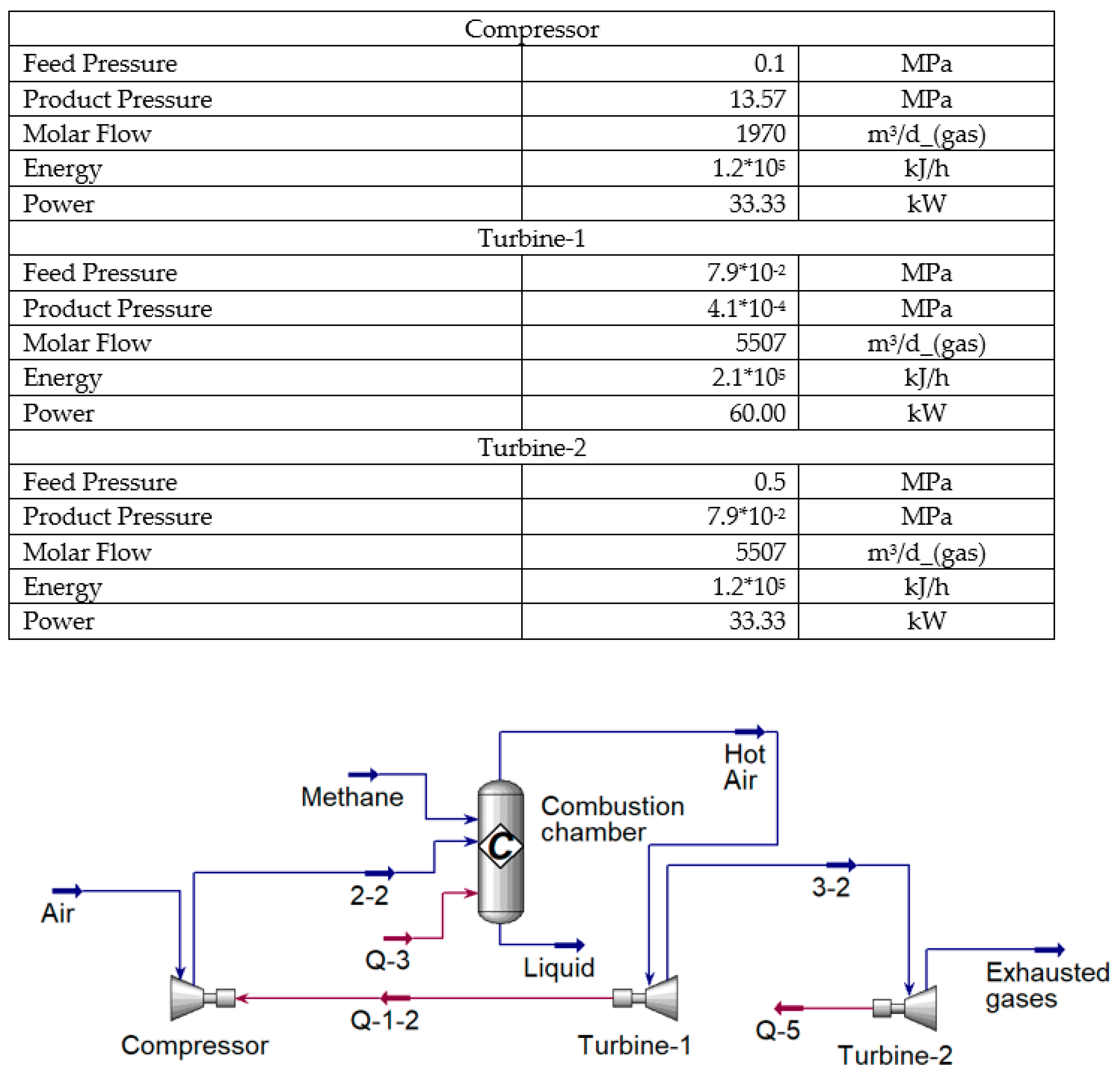
The simulation in Aspen HYSYS was performed in stages. Figure 5 shows the simulation model for the first part of a binary system with a gas turbine.
According to Figure 5, the compressor is installed on the same shaft as the turbine, which is divided into the models of Turbine-1 (to simulate the transfer of mechanical energy from the turbine to the compressor) and Turbine-2 (to simulate power generation). The combustion chamber burns a methane–air mixture to heat the compressed air, which is fed directly to the turbine. The power at the turbine shaft with the selected technological parameters of the process is about 60 kW. The exhaust gas temperature at the turbine outlet is about 310 °C, which allows using this heat for power generation in the ORC.
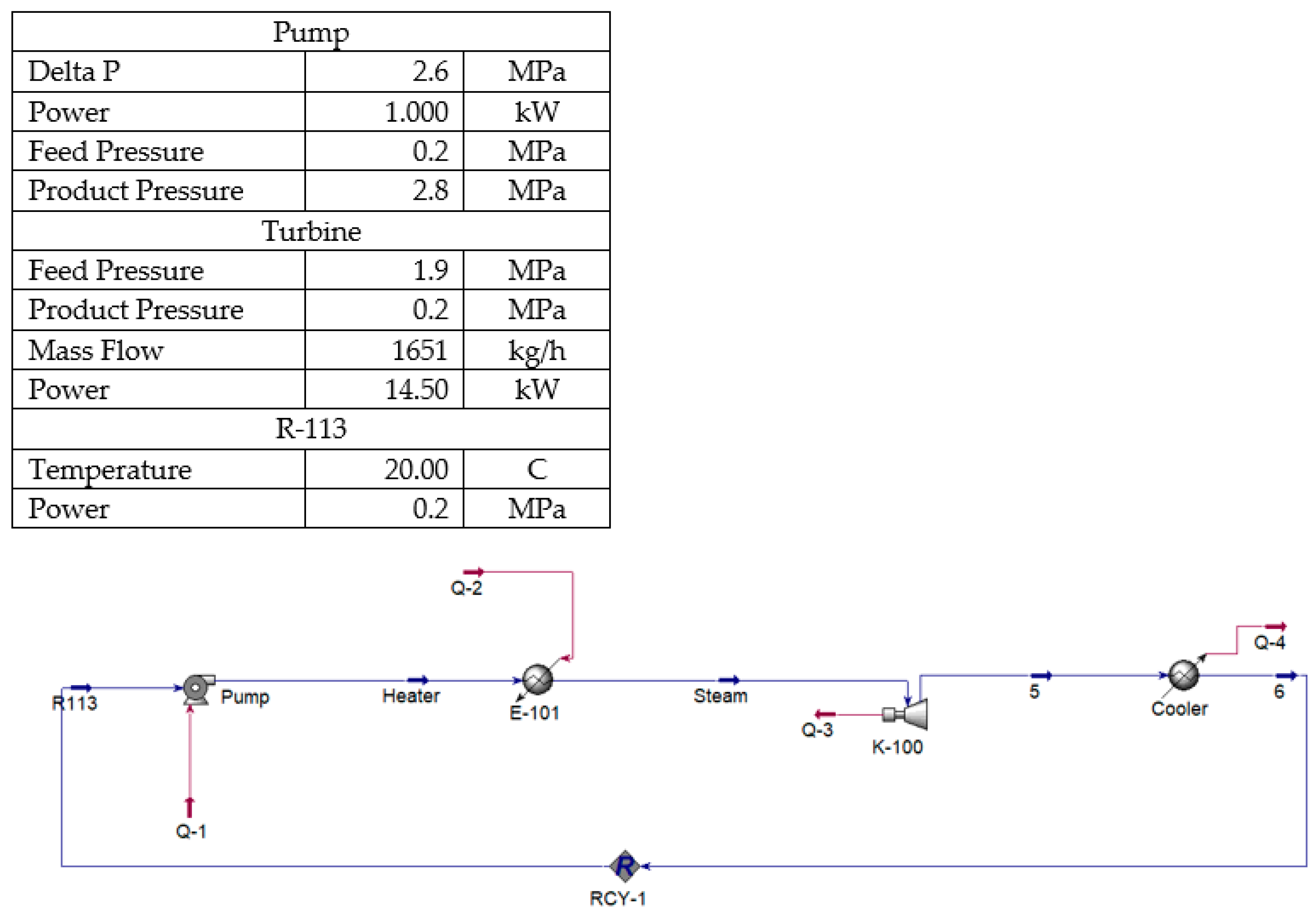
The second part of the binary system (ORC) was also modeled. The model for the organic cycle study is shown in Figure 6.

3.2. Results of Simulation in Mathlab Simulink

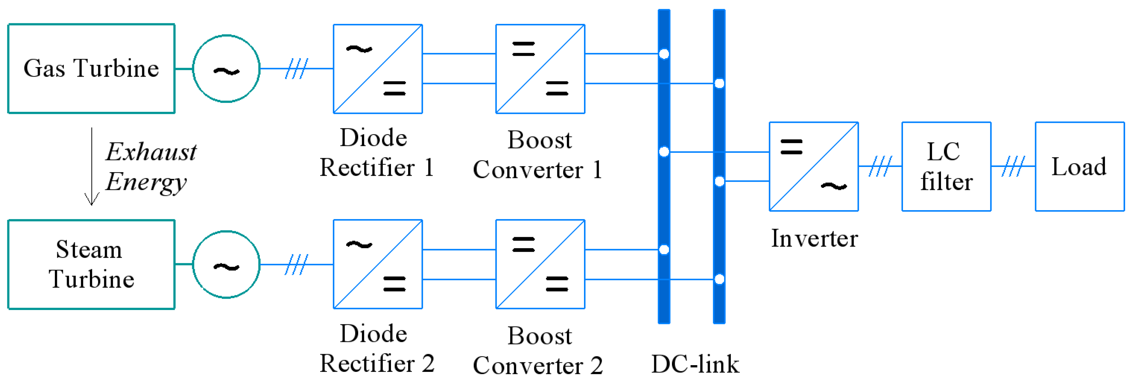
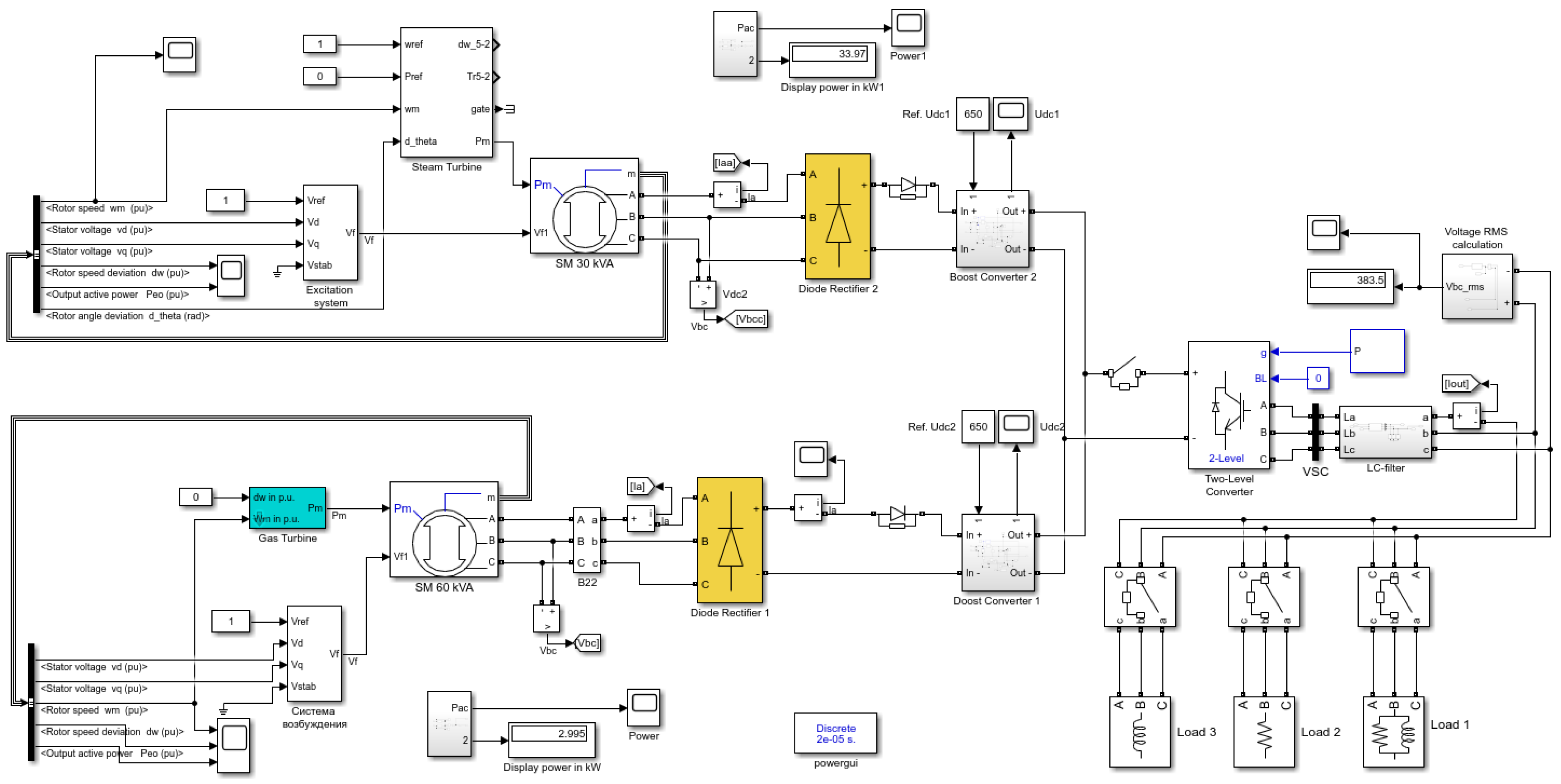
The electrical design of the binary energy system, which ensures efficient parallel operation of the MPU and APU, is shown in Figure 7.
The simulation model includes gas and steam turbines with 60 and 15 kVA synchronous generators respectively, passive diode rectifiers, stabilizing pulse width converters (PWCs), a common voltage inverter, an inductive-capacitive filter, and active-inductive load. The developed model in MATLAB Simulink is shown in Figure 8.
The simulation model was manually set up to simulate the operation of a gas turbine and a steam turbine on one common DC link. The rated rotational frequency of the micro-turbine was taken from the initial conditions, since the investigation of the dynamic characteristics of the turbines in a binary energy system was not the subject of the study.
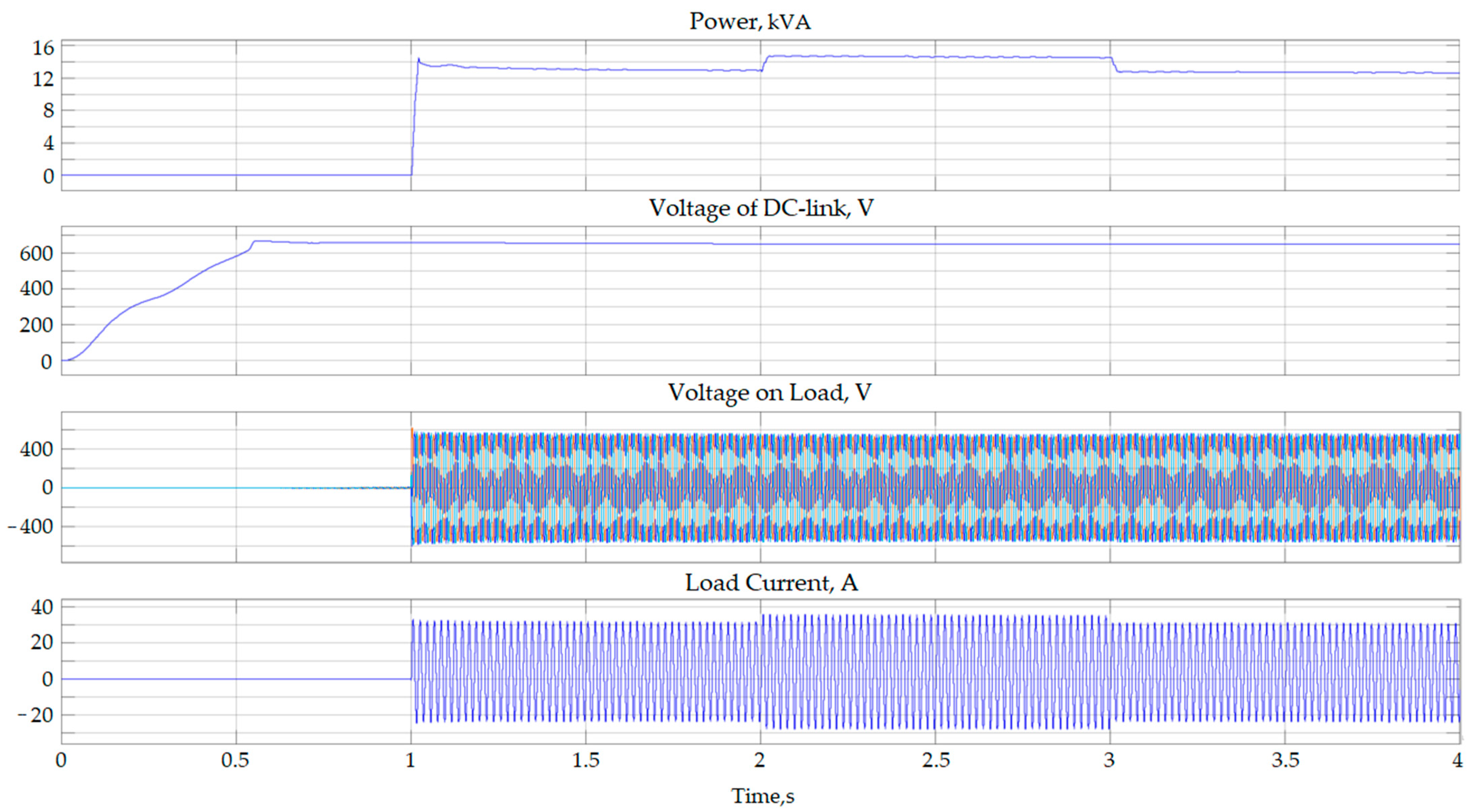
Figure 9 shows the oscillograms (from top to bottom): (1) apparent power; (2) DC bus voltage; (3) load line voltage; (4) phase load current.
For the first 0.5 s after switching on the electrical part of the binary system, which is defined as a set of inverters and switching devices, the DC link is charged to 650 V. In the 1st second of the simulation, an active-inductive load of 59.2 kvar (active power 58 kW and reactive power 12 kvar) is connected. In the 2nd second, an additional 4 kW active load is connected, which is switched off at the 3rd second.
A step-up PID with negative voltage feedback was proposed to stabilize the voltage in the PWC. The PID parameters were set, and the capacity and inductance of the DC link were selected.
According to the results, the oscillations in the DC link at the rated load are about 3 V, but can increase as a function of the load.
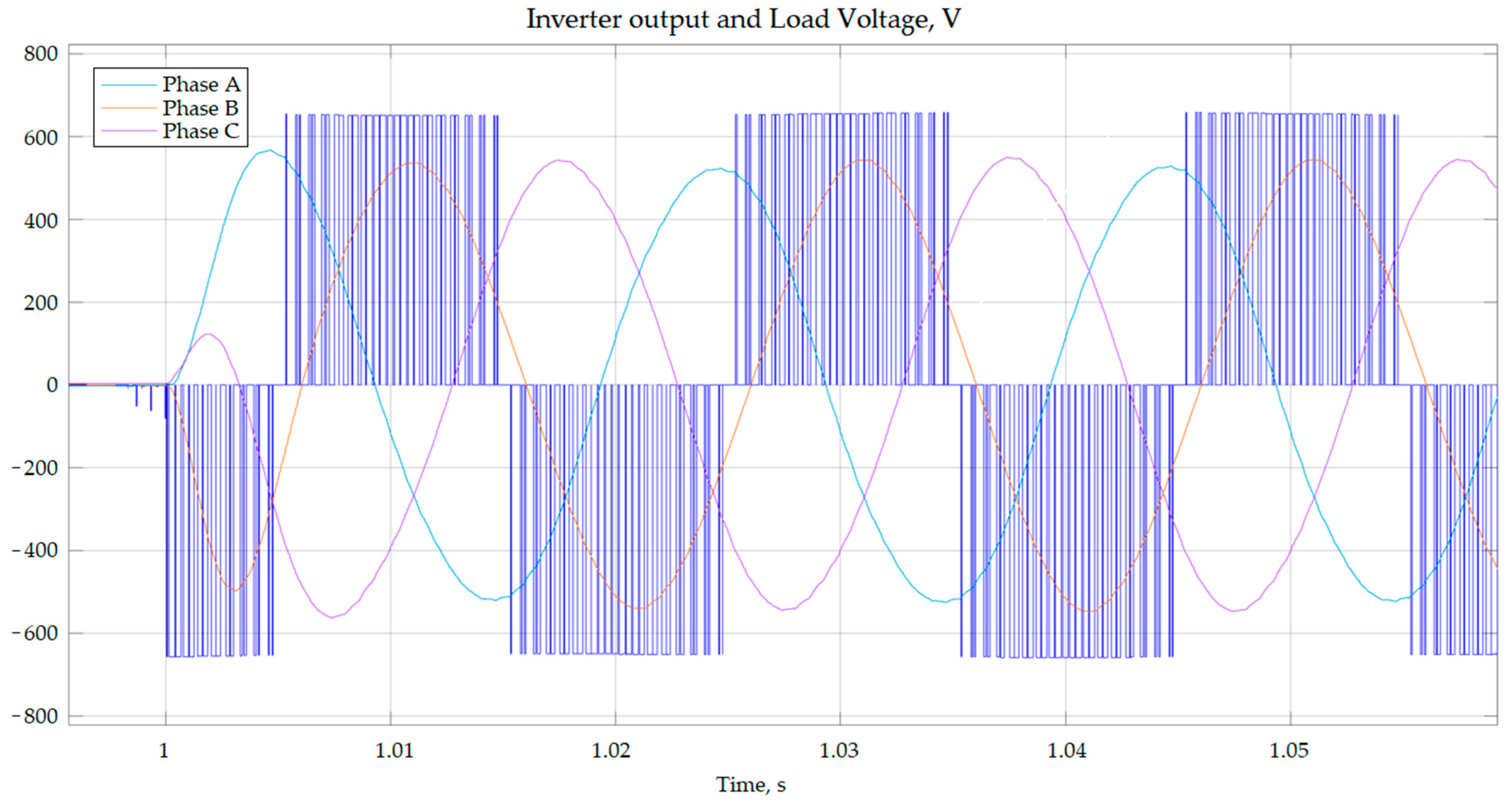
The oscillograms of the line voltage at the inverter output and the load line voltage are shown in Figure 10. The average value of the line voltage on the load is 388 V.
A similar simulation was performed for the electrical system of the second part in the binary system with a steam turbine. The oscillograms of the DC link voltage, line voltage, and load current are similarly shown in Figure 11. In the 1st second of the simulation, an active-inductive load of 20.6 kvar (20 kW active power and 5 kvar reactive power) is connected. In the 2nd second, an additional 4 kW active load is connected, which is switched off at the 3rd second.

3.3. Techno-Economic Assessment of the Developed Energy System

Based on the exergy analysis performed by the authors earlier, it was established that the total electrical power of the binary energy system can be calculated as follows [46]:
P b . c . = P r + ( 2 · P r · K t u · K l · K e x h ) · η i ,
where: P r —rated electrical power of the unit;
  • K t u —unit’s coefficient of technical usage;
  • K l —unit’s coefficient of load;
  • K e x h —coefficient of the heat energy losses in exhaust gases;
  • η i —internal efficiency of steam turbine cycle.
The values of the coefficients and internal efficiency of various steam turbine cycles were obtained during the analysis of the energy facilities’ operation parameters and theoretical research. Thus, the coefficient of the technical usage for the gas turbines reflects the time when the power unit was operational during the year ( K t u = 0.79–0.84). The coefficient of the load shows the level of the unit’s loading ( K l = 0.8–0.9). The coefficient of the heat energy losses in the exhaust gases was taken as 0.95. The results of the performed simulations are in agreement with the equation mentioned above.
A basic techno-economic assessment of the energy system was conducted. The capital (CAPEX) and operational (OPEX) expenditures of the proposed binary energy system were compared with those of a diesel power plant and a micro-turbine power plant (without the ORC part). The power systems were investigated under the conditions of the oil field located in the Arctic region. The power output of the power systems was upscaled to 1000 kW. Two types of fuels were considered: diesel fuel and petroleum gas. OPEX included the cost of the fuel for the power units. The cost of diesel fuel for the diesel power plant was 200% higher relative to its cost in the urban areas due to the need to transport the fuel to the remote Arctic location by sea. This made this type of power plant economically unfeasible after two years of operation. The micro-turbine power plant had lower CAPEX and OPEX then the developed structure in the first year of operation. However, because of the additional amount of generated energy under the same fuel consumption, the binary energy system had a shorter payback period. Initial calculations showed the capital investments were recouped in six years.
The generalized energy flow chart of the developed binary energy system is presented in Figure 12. This flow chart is drawn in such a way that the energy potential of the next element is subtracted from the previous one. Thermal energy, which is acquired through burning the hydrocarbon gas, at first is converted into electrical energy, and the rest may be transformed into heat or cold. The energy potential is given in units. Thus, if the initial energy is 100 units, then 50 units equal 50%, which is the total electrical efficiency of the binary energy system.

4. Discussion

The developed binary energy system can reach the electrical efficiency of 50% under the conditions considered in the research. The indicated value correlates with the results obtained by other researchers in similar works. In order to obtain high efficiency of power generation in an ORC, the properties of the low-boiling medium should match the thermobaric conditions of the technological process. Another important issue is the quality of the generated power. The hydrocarbon gases and refrigerants are quite different power sources, as are the corresponding gas and steam power generators. In order to synchronize the operational parameters, correct power electronics should be used in the system.

4.1. Results of Simulation in Aspen HYSYS

The model constructed in Aspen HYSYS confirms the efficient operation of the developed energy system design. Higher efficiency of the power units is achieved if the selected low-boiling medium corresponds to the operational conditions of the technological process. The considered power ratings of 60 kW for the MPU and approximately 12 kW for the APU (14.5 kW of power at the shaft of the generator with mechanical and electrical losses) coincide with the power range of the micro-power units. In addition, other low-boiling media can be selected under various thermobaric conditions.

4.2. Results of Simulation in MATLAB Simulink

The model constructed in MATLAB Simulink confirms the efficient operation of the electrical part of the binary energy system. The major issue of the micro-gas and steam power units is their different operational characteristics. Due to significant differences in the rotational frequency of the shafts in the power units, their synchronization is a complex process. Simulation of the functioning of the power electronics in the structure of the binary system shows reliable and efficient parallel operation of the power units. The presented oscillograms of the power, voltage, and current during connection and disconnection of the load to/from the MPU and APU illustrate the quality and stable parameters of the electrical energy in the power grid.

5. Conclusions

The efficiency of the developed energy system reaches 50%. Although large-scaled combined power systems can achieve higher efficiency, their application is not always possible in remote conditions. The simulation performed in MATLAB Simulink and Aspen HYSYS showed that the developed energy system can be efficiently used for the standalone power supply of various consumers with power demand of several hundred kilowatts. The gaseous fuel for the system may be natural gas, LNG, biogas, petroleum gas, etc.
The analysis of the use of different working cycles for micro-turbine units in modern power systems was carried out. The operational parameters of micro-gas turbine and micro-steam turbine units in a binary cycle were studied, taking into account the energy efficiency of low-boiling medium application.
Modeling of operational modes of binary energy units was carried out with regard to the identified energy-efficiency parameters of various analyzed low-boiling media to calculate the material and energy balance of the processes. For this purpose, general models of the considered energy processes and technological circuits were created.
There are several prospects for further research. If the gas turbine unit fueled by LNG is used, additional energy can be obtained by selecting a low-boiling medium, which will be condensed in the process of the cooling of the liquefied natural gas during regasification. In addition, according to investigations of the Allam cycle, CO2 in a supercritical state can be used as a low-boiling fluid, which will increase the efficiency of the process when using liquefied natural gas as an energy source. Further investigations will consider the application of the R744 refrigerant in the developed binary system to increase the environmental safety of the power generation with hydrocarbon gas as an energy source.

Author Contributions

Conceptualization, V.M. and G.B.; Formal analysis, E.L.; Investigation, A.L. (Alexander Lavrik) and A.L. (Anna Lavrik); Methodology, V.M.; Project administration, V.M.; Resources, E.L. and G.B.; Software, A.L. (Alexander Lavrik) and A.L. (Anna Lavrik); Validation, G.B.; Visualization, E.L.; Writing—original draft, V.M.; Writing—review and editing, E.L. and G.B. All authors have read and agreed to the published version of the manuscript.

Funding

The research was performed at the expense of the subsidy for the state assignment in the field of scientific activity for 2021 №FSRW-2020-0014.

Institutional Review Board Statement

Not applicable.

Informed Consent Statement

Not applicable.

Data Availability Statement

The data presented in this study are available on request from the corresponding author. The data are not publicly available due to its storage in private networks.

Conflicts of Interest

The authors declare no conflict of interest.

Abbreviations

The following abbreviations are used in this manuscript:
APUauxiliary power unit
CAPEX capital expenditures
CHP combined heat and power
GMPU gas microturbine power unit
GRU gas-reciprocating unit
GTU gas turbine unit
LNG liquefied natural gas
MPU main power unit
NG natural gas
OPEX operational expenditures
ORC organic Rankine cycle
PWC pulse width converter

References

  1. Hansen, J.; Johnson, D.; Lacis, A.; Lebedeff, S.; Lee, P.; Rind, D.; Russel, G. Climate Impact of Increasing Atmospheric Carbon Dioxide. Science 1981, 213, 957–966. [Google Scholar] [CrossRef] [Green Version]
  2. Tokarska, K.; Gillett, N.; Weaver, A.; Arora, V.K.; Eby, M. The climate response to five trillion tonnes of carbon. Nat. Clim. Chang. 2016, 6, 851–855. [Google Scholar] [CrossRef]
  3. Solomon, S.; Plattner, G.-K.; Knutti, R.; Friedlingstein, P. Irreversible climate change due to carbon dioxide emissions. Proc. Natl. Acad. Sci. USA 2009, 106, 1704–1709. [Google Scholar] [CrossRef] [PubMed] [Green Version]
  4. Rogelj, J.; den Elzen, M.; Höhne, N.; Fransen, T.; Fekete, H.; Winkler, H.; Schaeffer, R.; Sha, F.; Riahi, K.; Meinshausen, M. Paris Agreement Climate Proposals Need a Boost to Keep Warming Well Below 2  °C. Nature 2016, 534, 631–639. [Google Scholar] [CrossRef] [Green Version]
  5. Marcotullio, P.J.; Sarzynski, A.; Albrecht, J.; Schulz, N.; Garcia, J. The geography of global urban greenhouse gas emissions: An exploratory analysis. Clim. Chang. 2013, 121, 621–634. [Google Scholar] [CrossRef]
  6. Toro, N.; Robles, P.; Jeldres, R.I. Seabed mineral resources, an alternative for the future of renewable energy: A critical review. Ore Geol. Rev. 2020, 126, 103699. [Google Scholar] [CrossRef]
  7. Shklyarskiy, Y.E.; Guerra, D.D.; Iakovleva, E.V.; Rassõlkin, A. The influence of solar energy on the development of the mining industry in the Republic of Cuba. J. Min. Inst. 2021, 249, 427–440. [Google Scholar] [CrossRef]
  8. Wang, Z.; Burra, K.G.; Lei, T.; Gupta, A.K. Co-pyrolysis of waste plastic and solid biomass for synergistic production of biofuels and chemicals—A review. Prog. Energy Combust. Sci. 2021, 84, 100899. [Google Scholar] [CrossRef]
  9. Nazari, M.T.; Mazutti, J.; Basso, L.G.; Colla, L.M.; Brandli, L. Biofuels and their connections with the sustainable development goals: A bibliometric and systematic review. Environ. Dev. Sustain. 2021, 23, 11139–11156. [Google Scholar] [CrossRef]
  10. Ocean Energy Europe. Available online: https://www.oceanenergy-europe.eu/ (accessed on 25 June 2021).
  11. Ocean Energy Status Report. JRC. 2014. Available online: https://setis.ec.europa.eu/sites/default/files/reports/2014-JRC-Ocean-Energy-Status-Report.pdf (accessed on 25 June 2021).
  12. IRENA Wave Energy Technology Brief. 2014. Available online: https://www.irena.org/documentdownloads/publications/wave-energy_v4_web.pdf (accessed on 25 June 2020).
  13. Cameron, L.; Doherty, R.; Henry, A.; Doherty, K.; Van’t Hoff, J.; Kaye, D.; Naylor, D. Design of the next generation of the Oyster wave energy converter. In Proceedings of the 3rd International Conference on Ocean Energy, Bilbao, Spain, 6–8 October 2010. [Google Scholar]
  14. Lu, S.-M. A global review of enhanced geothermal system (EGS). Renew. Sustain. Energy Rev. 2017, 81, 2902–2921. [Google Scholar] [CrossRef]
  15. Dobson, P.F. A review of exploration methods for discovering hidden geothermal systems. Geotherm. Resour. Counc. Trans. 2016, 40, 695–706. [Google Scholar]
  16. Litvinenko, V.; Bowbrick, I.; Naumov, I.; Zaitseva, Z. Global guidelines and requirements for professional competencies of natural resource extraction engineers: Implications for ESG principles and sustainable development goals. J. Clean. Prod. 2022, 338, 130530. [Google Scholar] [CrossRef]
  17. Ritchie, H.; Roser, M. Energy. Available online: https://ourworldindata.org/energy (accessed on 25 June 2021).
  18. Zhu, Y.; Tomsovic, K. Optimal distribution power flow for systems with distributed energy resources. Electr. Power Energy Syst. 2007, 29, 260–267. [Google Scholar] [CrossRef]
  19. Jurado, F.; Saenz, J.R. Adaptive control of a fuel cell-micro turbine hybrid power plant. IEEE Trans. Energy Convers. 2003, 18, 342–347. [Google Scholar] [CrossRef]
  20. Sultanbekov, R.; Islamov, S.; Mardashov, D.; Beloglazov, I.; Hemmingsen, T. Research of the influence of marine residual fuel composition on sedimentation due to incompatibility. J. Mar. Sci. Eng. 2021, 14, 1067. [Google Scholar] [CrossRef]
  21. Sultanbekov, R.; Beloglazov, I.; Islamov, S.; Ong, M.C. Exploring of the incompatibility of marine residual fuel: A case study using machine learning methods. Energies 2021, 14, 8422. [Google Scholar] [CrossRef]
  22. Anders, M. Analysis of a gas turbine driven hybrid drive system for heavy vehicles. Ph.D. Thesis, School of Electrical Engineering and Information Technology (KTH), Stockholm, Sweden, 1999. [Google Scholar]
  23. Al-Hinai, A.; Feliachi, A. Dynamic Model of a Micro Turbine Used as a Distributed Generator. In Proceedings of the 34th Southeastern Symposium on system Theory, Huntsville, AL, USA, 19 March 2002; pp. 209–213. [Google Scholar]
  24. Moustafa, I.; Hassan, M. Speed Control of Micro Gas Turbine with PMSG using Evolutionary Computational Techniques. In The International Conference on Electrical Engineering; Military Technical College: Cairo, Egypt, 2016; Volume 10, pp. 1–16. [Google Scholar] [CrossRef]
  25. Frost & Sullivan. Combined Heat and Power: Integrating Biomass Technologies in Buildings for Efficient Energy Consumption; Report Number: 9835-14; Frost & Sullivan: Mountain View, CA, USA, 2011. [Google Scholar]
  26. Ivanov, A.V.; Strizhenok, A.V.; Suprun, I.K. Ecological and economic justification of the utilization of associated petroleum gas at oil fields of Russian Federation. Geol. I Geofiz. Yuga Ross. 2020, 10, 114–126. [Google Scholar] [CrossRef]
  27. Duan, J.; Sun, L.; Wang, G.; Wu, F. Nonlinear modeling of regenerative cycle micro gas turbine. Energy 2015, 91, 168–175. [Google Scholar] [CrossRef]
  28. Abdollahi, S.E.; Vahedi, A. Dynamic Modeling of Micro-Turbine Generation Systems Using Matlab/Simulink. Renew. Energy Power Qual. J. 2005, 1, 168–175. [Google Scholar] [CrossRef]
  29. Nascimento, M.A.R.; Rodrigues, L.O.; dos Santos, E.C.; Gomes, E.E.B.; Dias, F.L.G.; Gutiérrez Velásques, E.I.; Miranda Carillo, M.A. Micro gas turbine engine: A review. In Progress in Gas Turbine Performance; IntechOpen: London, UK, 2013; pp. 107–141. [Google Scholar]
  30. Konečná, E.; Teng, S.Y.; Máša, V. New insights into the potential of the gas microturbine in microgrids and industrial applications. Renew. Sustain. Energy Rev. 2020, 134, 110078. [Google Scholar] [CrossRef]
  31. Borbely, A.; Kreider, J.F. Distributed Generation: The Power Paradigm for the New Millennium; CRC Press: Boca Raton, FL, USA, 2001. [Google Scholar]
  32. Rassokhin, V.A.; Rassokhin, V.A.; Zabelin, N.A.; Matveev, Y.V.; Kharisov, I.S. Methodology for experimental research of low-power turbine unit stages at SPbSPU stands. Sci. Educ. 2012, 1, 119–122. (In Russian) [Google Scholar]
  33. Gupta, K.K.; Rehman, A.; Sarviya, R.M. Bio-fuels for the gas turbine: A review. Renew. Sustain. Energy Rev. 2010, 14, 2946–2955, ISSN 1364-0321. [Google Scholar] [CrossRef]
  34. Paoli, N. Simulation Models for Analysis and Optimization of Gas Turbine Cycles. 2009. Available online: https://etd.adm.unipi.it/t/etd-04062009-132133/ (accessed on 25 June 2021).
  35. Gusarov, V.A.; Kharchenko, V.V. 2018 Micro gas turbine unit GTE-10S. Vestnik 2018, 30, 49–55. (In Russian) [Google Scholar]
  36. Invernizzi, C.; Iora, P.; Silva, P. Bottoming micro-Rankine cycles for micro-gas turbines. Appl. Therm. Eng. 2007, 27, 100–110. [Google Scholar] [CrossRef]
  37. Mahmoudi, A.; Fazli, M.; Morad, M.R. A recent review of waste heat recovery by Organic Rankine Cycle. Appl. Therm. Eng. 2018, 143, 660–675. [Google Scholar] [CrossRef]
  38. Hansaenergo. Steam Microturbines 50–3000 kW. Available online: http://hansaenergo.ru/produktsiya/turbines/pbs/microturbine. (accessed on 25 June 2021).
  39. Dibyendu, R.; Samiran, S.; Sudip, G. Performance assessment of a biomass fuelled advanced hybrid power generation system. Renew. Energy 2020, 162, 639–661, ISSN 0960-1481. [Google Scholar] [CrossRef]
  40. Yağlı, H.; Koç, Y.; Kalay, H. Optimisation and exergy analysis of an organic Rankine cycle (ORC) used as a bottoming cycle in a cogeneration system producing steam and power. Sustain. Energy Technol. Assess. 2020, 44, 100985. [Google Scholar] [CrossRef]
  41. Habibi, H.; Zoghi, M.; Chitsaz, A.; Javaherdeh, K.; Ayazpour, M.; Bellos, E. Working fluid selection for regenerative super-critical Brayton cycle combined with bottoming ORC driven by molten salt solar power tower using energy-exergy analysis. Sustain. Energy Technol. Assess. 2020, 39, 100699, ISSN 2213-1388. [Google Scholar] [CrossRef]
  42. Ping, X.; Yang, F.; Zhang, H.; Xing, C.; Wang, C.; Zhang, W.; Wang, Y. Energy, economic and environmental dynamic response characteristics of organic Rankine cycle (ORC) system under different driving cycles. Energy 2022, 246, 123438. [Google Scholar] [CrossRef]
  43. Allam, R.; Martin, S.; Forrest, B.; Fetvedt, J.; Lu, X.; Freed, D.; Brown, G.W., Jr.; Sasaki, T.; Itoh, M.; Manning, J. Demonstration of the Allam Cycle: An Update on the Development Status of a High Efficiency Supercritical Carbon Dioxide Power Process Employing Full Carbon Capture. Energy Procedia 2017, 114, 5948–5966, ISSN 1876-6102. [Google Scholar] [CrossRef]
  44. Zhu, Z.; Chen, Y.; Wu, J.; Zhang, S.; Zheng, S. A modified Allam cycle without compressors realizing efficient power generation with peak load shifting and CO2 capture. Energy 2019, 174, 478–487, ISSN 0360-5442. [Google Scholar] [CrossRef]
  45. Morenov, V.; Leusheva, E.; Buslaev, G.; Gudmestad, O.T. System of Comprehensive Energy-Efficient Utilization of Associated Petroleum Gas with Reduced Carbon Footprint in the Field Conditions. Energies 2020, 13, 4921. [Google Scholar] [CrossRef]
  46. Salehi, A.; Seifi, A.R.; Safavi, A.A. Combined-Cycle Plant Simulation Toolbox for Power Plant Simulator. Pac. J. Sci. Technol. 2008, 9, 97–109. [Google Scholar]
  47. Rai, J.N.; Naimul, H.; Arora, B.B.; Garai, R.; Kapoor, R. Performance Analysis of CCGT Power Plant using MATLAB/Simulink Based Simulation. Int. J. Adv. Res. Technol. 2013, 2, 285–290. [Google Scholar]
  48. Leusheva, E.L.; Morenov, V.A. Development of combined heat and power system with binary cycle for oil and gas enterprises power supply. Neftyanoe Khozyaystvo-Oil Ind. 2017, 7, 104–106. [Google Scholar] [CrossRef]
  49. Hu, Y.; Gao, Y.; Lv, H.; Xu, G.; Dong, S. New Integration System for Natural Gas Combined Cycle Power Plants with CO2 Capture and Heat Supply. Energies 2018, 11, 3055. [Google Scholar] [CrossRef] [Green Version]
  50. Tavakoli, M.R.B.; Vahidi, B.; Gawlik, W. An Educational Guide to Extract the Parameters of Heavy Duty Gas Turbines Model in Dynamic Studies Based on Operational Data. IEEE Trans. Power Syst. 2009, 24, 1366–1374. [Google Scholar] [CrossRef]
  51. Gasturbine.zip. MATLAB Central File Exchange. Available online: https://www.mathworks.com/matlabcentral/fileexchange/47495-gasturbine-zip (accessed on 25 June 2021).
  52. Skamyin, A.; Shklyarskiy, Y.; Dobush, V.; Dobush, I. Experimental Determination of Parameters of Nonlinear Electrical Load. Energies 2021, 14, 7762. [Google Scholar] [CrossRef]
  53. Shklyarskiy, Y.; Skamyin, A.; Vladimirov, I.; Gazizov, F. Distortion load identification based on the application of compensating devices. Energies 2020, 13, 1430. [Google Scholar] [CrossRef] [Green Version]
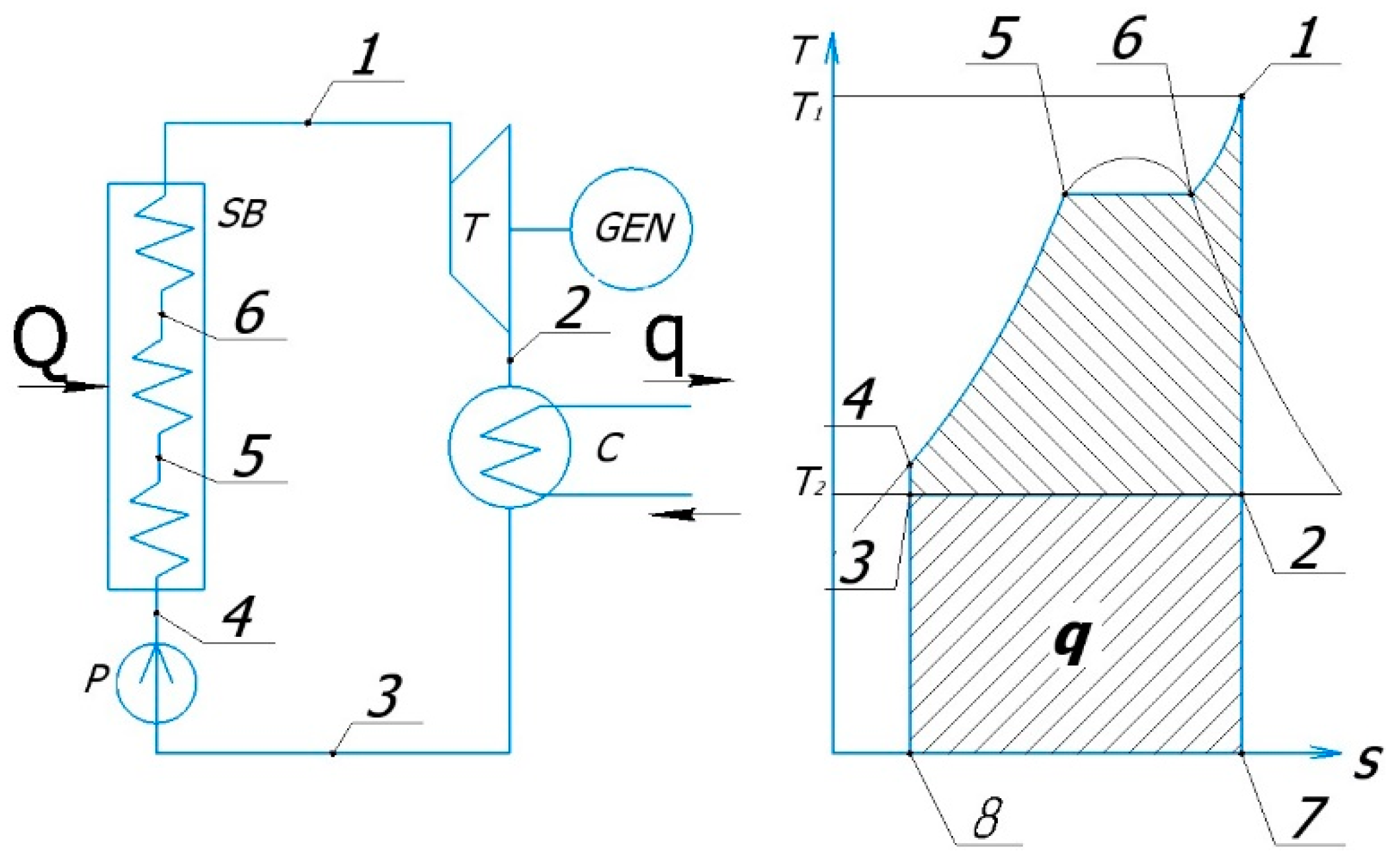
Figure 1. Scheme for generating thermal and electric power by means of a micro-turbine operating in the Rankine cycle with superheated steam. SB—steam boiler; T—steam turbine; GEN—electric generator; C—condenser; P—pump.
Energies 15 02551 g001
Figure 2. Operational scheme of the investigated binary energy system combining main and auxiliary power units [45].
Energies 15 02551 g002
Figure 3. The simulation model of the system in Aspen HYSYS.
Energies 15 02551 g003
Figure 4. Simulation model of a single-shaft gas turbine built in MATLAB Simulink according to Rowen [51].
Energies 15 02551 g004
Figure 5. Simulation model for the first part of a binary system with a gas turbine.
Energies 15 02551 g005
Figure 6. Simulation model for the second part of a binary system with a steam turbine.
Energies 15 02551 g006
Figure 7. Electrical design of the binary energy system.
Energies 15 02551 g007
Figure 8. Simulation model for the electrical part of the binary energy system.
Energies 15 02551 g008
Figure 9. Voltage oscillograms on the DC bus, load line voltage, and load current during gas turbine operation.
Energies 15 02551 g009
Figure 10. Oscillograms of the line voltage at the inverter output and the load line voltage.
Energies 15 02551 g010
Figure 11. Oscillograms of the apparent power, DC link voltage, load voltage, and load current.
Energies 15 02551 g011
Figure 12. Energy flow chart of the binary energy system.
Energies 15 02551 g012
Table 1. Physical and thermal properties of the R113.
PropertyValue
Molecular weight187.4
Density at 25 °C1.56 g/cm3
Boiling point47.5
Critical point density0.57 g/cm3
Critical point pressure3.406 MPa
Critical point temperature214.3 °C
Publisher’s Note: MDPI stays neutral with regard to jurisdictional claims in published maps and institutional affiliations.