
Deeper Understanding of Ternary Eutectic Carbonates/Ceria-Based Oxide Composite Electrolyte through Thermal Cycling

Abstract
:1. Introduction
2. Materials and Methods
2.1. Preparation of Sm-Doped Ceria-(Li,Na,K)2CO3 Composite Electrolyte
2.2. Electrochemical Analysis
2.3. Phase and Microstructural Analysis
2.4. Thermal Analysis
3. Results and Discussion

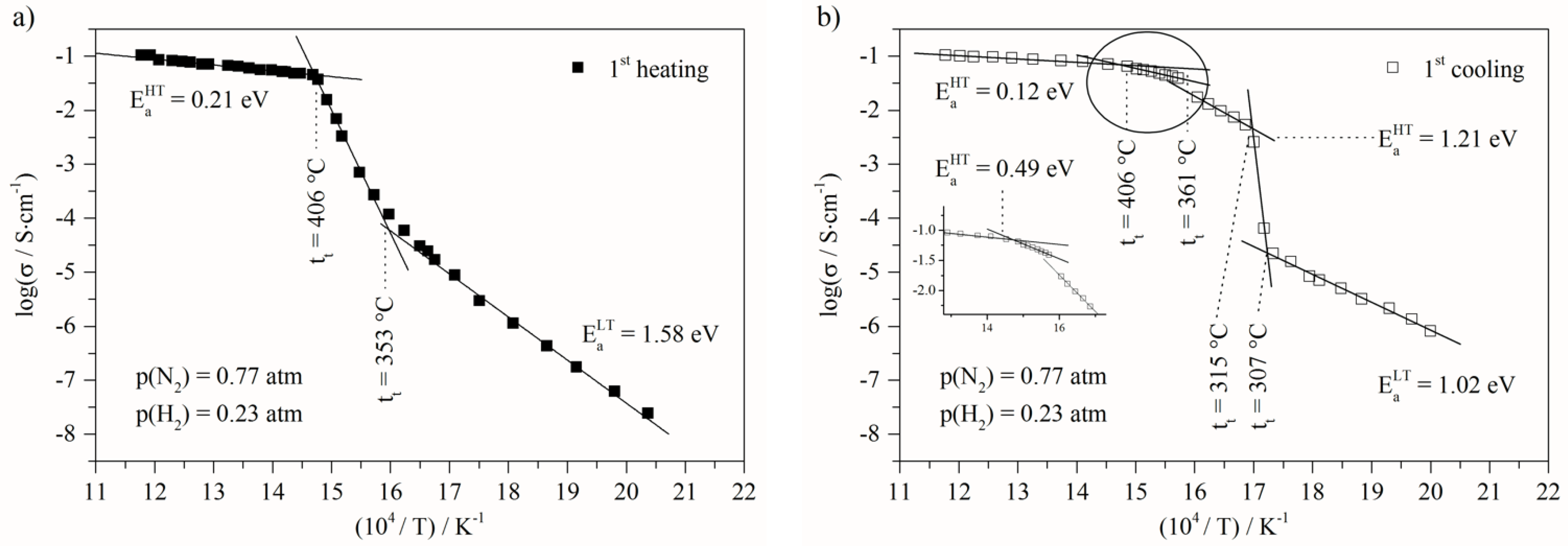
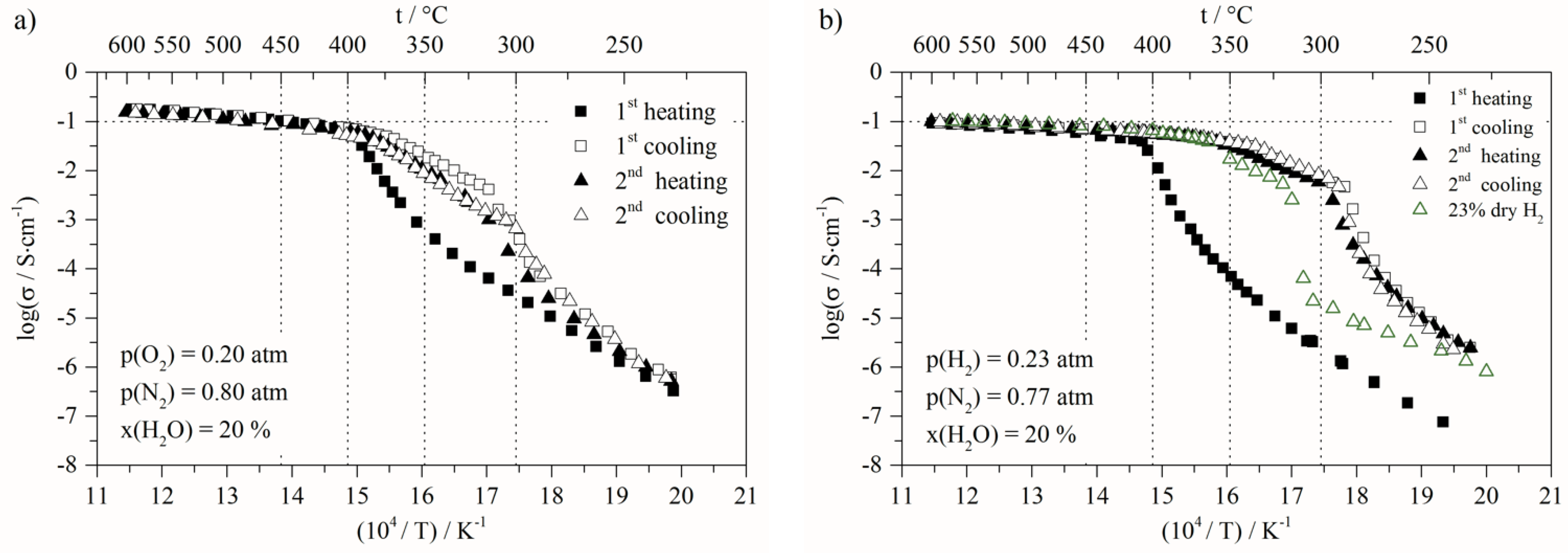
- At low temperature (<307 °C), before the first transition, the activation energy decreased from 1.58 eV to 1.02 eV, related to the first heating and cooling steps, respectively;
- At high temperature (>410 °C) the activation energy decreased from 0.21 eV to 0.12 eV. This variation clearly indicates that the transport mechanisms and/or the species involved are modified. Moreover, the next change of slope is observed at around 406 °C down to 361 °C, and the activation value is 0.49 eV (Figure 3b). This value is close to the isolated molten ternary eutectic as reported by Ward et al. [50]. However, this should have been the same value of up to 490 °C, as in his work, which was not the case in our study; as this temperature is included in the temperature range, for which the activation is lower, being 0.12 eV. The other assumption is that this activation energy value of 0.49 eV quite often corresponds to protonic conduction through hydroxide ions [54,55,56]. The following slope, around 360–315 °C temperature range, is close to 1.2 eV, and is not fully identified. Nevertheless, assuming the partial transformation of carbonates into hydroxides, this could be ascribed to hydroxide transport mixed with carbonates into the porous solid matrix. The activation energy values corresponding to the different regions of the Arrhenius plots present in this paper are calculated in the same way, and can be found in the Supplementary Information.

4. Conclusions
Supplementary Materials
Author Contributions
Funding
Institutional Review Board Statement
Informed Consent Statement
Conflicts of Interest
References
- Zhu, B.; Mellander, B.E. Proton Conduction in Nitrate-Based Oxides and Related Ceramics at Intermediate Temperatures. Solid State Ion. 1994, 70, 285–290. [Google Scholar] [CrossRef]
- Ricca, C.; Albin, V.; Labat, F.; Adamo, C.; Cassir, M.; Ringuedé, A. A First Combined Electrochemical and Modelling Strategy on Composite Carbonate/Oxide Electrolytes for Hybrid Fuel Cells. Int. J. Hydrog. Energy 2016, 41, 18778–18787. [Google Scholar] [CrossRef]
- Jaiswal, N.; Upadhyay, S.; Kumar, D.; Parkash, O. Ca2+ and Sr2+ Co-Doped Ceria/Carbonates Nanocomposites for Low Temperature Solid Oxide Fuel Cells: Composite Effect. Ceram. Int. 2015, 41, 15162–15169. [Google Scholar] [CrossRef]
- Jaiswal, N.; Upadhyay, S.; Kumar, D.; Parkash, O. Enhanced Ionic Conductivity in La3+ and Sr2+ Co-Doped Ceria: Carbonate Nanocomposite. Ionics 2015, 21, 2277–2283. [Google Scholar] [CrossRef]
- Ahmed, A.; Raza, R.; Khalid, M.S.; Saleem, M.; Alvi, F.; Javed, M.S.; Sherazi, T.A.; Akhtar, M.N.; Akram, N.; Ahmad, M.A.; et al. Highly Efficient Composite Electrolyte for Natural Gas Fed Fuel Cell. Int. J. Hydrog. Energy 2016, 41, 6972–6979. [Google Scholar] [CrossRef]
- Asghar, M.I.; Jouttijärvi, S.; Lund, P.D. High Performance Ceramic Nanocomposite Fuel Cells Utilizing LiNiCuZn-Oxide Anode Based on Slurry Method. Int. J. Hydrog. Energy 2018, 43, 12797–12802. [Google Scholar] [CrossRef]
- Tanwar, K.; Jaiswal, N.; Sharma, P.; Kumar, D.; Parkash, O. Structural Analysis of Ce0.83Dy0.14Ca0.03O1.90(CDC) and Enhanced Electrical Conductivity of Its Composites with Alkali Carbonates for LT-SOFCs. J. Alloy. Compd. 2018, 741, 532–541. [Google Scholar] [CrossRef]
- Singh, M.; Singh, A.K. Space Charge Layer Induced Superionic Conduction and Charge Transport Behaviour of “Alkali Carbonates and Tri-Doped Ceria Nanocomposites” for LT-SOFCs Applications. Ceram. Int. 2021, 47, 1218–1228. [Google Scholar] [CrossRef]
- Zhu, B. Advantages of Intermediate Temperature Solid Oxide Fuel Cells for Tractionary Applications. J. Power Sources 2001, 93, 82–86. [Google Scholar] [CrossRef]
- Zhu, B.; Mellander, B.E. Performance of intermediate temperature SOFCs with composite electrolytes. In Solid Oxide Fuel Cells-VI; Singhal, S.C., Dokiya, M., Eds.; The Electrochemical Society, Inc.: Pennington, NJ, USA, 1999; Volume 1999. [Google Scholar]
- Fu, Q.X.; Zha, S.W.; Zhang, W.; Peng, D.K.; Meng, G.Y.; Zhu, B. Intermediate Temperature Fuel Cells Based on Doped Ceria-LiCl-SrCl2 composite Electrolyte. J. Power Sources 2002, 104, 73–78. [Google Scholar] [CrossRef]
- Slim, C.; Baklouti, L.; Cassir, M.; Ringuedé, A. Structural and Electrochemical Performance of Gadolinia-Doped Ceria Mixed with Alkali Chlorides (LiCl-KCl) for Intermediate Temperature-Hybrid Fuel Cell Applications. Electrochim. Acta 2014, 123, 127–134. [Google Scholar] [CrossRef]
- Shi, R.; Chen, W.; Hu, W.; Liu, J.; Wang, H. SrCe0.9Sm0.1O3-α compounded with NaCl-KCl as a Composite Electrolyte for Intermediate Temperature Fuel Cell. Materials 2018, 11, 1583. [Google Scholar] [CrossRef] [PubMed] [Green Version]
- Sun, L.; Du, R.; Wang, H.; Li, H. Intermediate Temperature Electrochemical Properties of Yb3+ doped SrCeO3− Carbonate and Chloride Composite Electrolytes. Int. J. Electrochem. Sci. 2018, 13, 5054–5060. [Google Scholar] [CrossRef]
- Zhu, B. Functional Ceria–Salt-Composite Materials for Advanced ITSOFC Applications. J. Power Sources 2003, 114, 1–9. [Google Scholar] [CrossRef]
- Zhu, B.; Mat, M.D. Studies on Dual Phase Ceria-Based Composites in Electrochemistry. Int. J. Electrochem. Sci. 2006, 1, 383–402. [Google Scholar]
- Zhu, B.; Li, S.; Mellander, B.E. Theoretical Approach on Ceria-Based Two-Phase Electrolytes for Low Temperature (300–600 °C) Solid Oxide Fuel Cells. Electrochem. Commun. 2008, 10, 302–305. [Google Scholar] [CrossRef]
- Yao, C.; Meng, J.; Liu, X.; Zhang, X.; Liu, X.; Meng, F.; Wu, X.; Meng, J. Enhanced Ionic Conductivity in Gd-Doped Ceria and (Li/Na)2SO4 Composite Electrolytes for Solid Oxide Fuel Cells. Solid State Sci. 2015, 49, 90–96. [Google Scholar] [CrossRef]
- Wang, H.; Hu, T.; Xi, G. A Novel Gd3+ and Yb3+ Co-Doped Ceria-Sulphate Composite Electrolyte for Intermediate-Temperature Fuel Cells. Ceram. Int. 2020, 46, 8695–8699. [Google Scholar] [CrossRef]
- Huang, J.; Gao, Z.; Mao, Z. Effects of Salt Composition on the Electrical Properties of Samaria-Doped Ceria/Carbonate Composite Electrolytes for Low-Temperature SOFCs. Int. J. Hydrog. Energy 2010, 35, 4270–4275. [Google Scholar] [CrossRef]
- Jing, Y.; Lund, P.; Asghar, M.I.; Li, F.; Zhu, B.; Wang, B.; Zhou, X.; Chen, C.; Fan, L. Non-Doped CeO2-Carbonate Nanocomposite Electrolyte for Low Temperature Solid Oxide Fuel Cells. Ceram. Int. 2020, 46, 29290–29296. [Google Scholar] [CrossRef]
- Huang, J.; Yang, L.; Gao, R.; Mao, Z.; Wang, C. A High-Performance Ceramic Fuel Cell with Samarium Doped Ceria-Carbonate Composite Electrolyte at Low Temperatures. Electrochem. Commun. 2006, 8, 785–789. [Google Scholar] [CrossRef]
- Huang, J.; Mao, Z.; Liu, Z.; Wang, C. Development of Novel Low-Temperature SOFCs with Co-Ionic Conducting SDC-Carbonate Composite Electrolytes. Electrochem. Commun. 2007, 9, 2601–2605. [Google Scholar] [CrossRef]
- Huang, J.; Mao, Z.; Liu, Z.; Wang, C. Performance of Fuel Cells with Proton-Conducting Ceria-Based Composite Electrolyte and Nickel-Based Electrodes. J. Power Sources 2008, 175, 238–243. [Google Scholar] [CrossRef]
- Huang, J.; Gao, R.; Mao, Z.; Feng, J. Investigation of La2NiO4+δ-Based Cathodes for SDC-Carbonate Composite Electrolyte Intermediate Temperature Fuel Cells. Int. J. Hydrog. Energy 2010, 35, 2657–2662. [Google Scholar] [CrossRef]
- Gao, Z.; Mao, Z.; Wang, C.; Huang, J.; Liu, Z. Composite Electrolyte Based on Nanostructured Ce0.8Sm0.2O1.9 (SDC) for Low-Temperature Solid Oxide Fuel Cells Zhan. Int. J. Energy Res. 2009, 33, 1138–1144. [Google Scholar] [CrossRef]
- Yao, X.; Li, P.; Yu, B.; Yang, F.; Li, J.; Zhao, Y.; Li, Y. Hydrothermally Synthesized NiO-Samarium Doped Ceria Nano-Composite as an Anode Material for Intermediate-Temperature Solid Oxide Fuel Cells. Int. J. Hydrog. Energy 2017, 42, 22192–22200. [Google Scholar] [CrossRef]
- Xia, C.; Li, Y.; Tian, Y.; Liu, Q.; Wang, Z.; Jia, L.; Zhao, Y.; Li, Y. Intermediate Temperature Fuel Cell with a Doped Ceria-Carbonate Composite Electrolyte. J. Power Sources 2010, 195, 3149–3154. [Google Scholar] [CrossRef]
- Asghar, M.I.; Jouttijärvi, S.; Jokiranta, R.; Lund, P.D. Remarkable Ionic Conductivity and Catalytic Activity in Ceramic Nanocomposite Fuel Cells. Int. J. Hydrog. Energy 2018, 43, 1–8. [Google Scholar] [CrossRef]
- Song, S.A.; Jang, S.C.; Han, J.; Yoon, S.P.; Nam, S.W.; Oh, I.H.; Lim, T.H. Enhancement of Cell Performance Using a Gadolinium Strontium Cobaltite Coated Cathode in Molten Carbonate Fuel Cells. J. Power Sources 2011, 196, 9900–9905. [Google Scholar] [CrossRef]
- Li, S.; Sun, J. Electrochemical Performances of NANOCOFC in MCFC Environments. Int. J. Hydrog. Energy 2010, 35, 2980–2985. [Google Scholar] [CrossRef]
- Benamira, M.; Ringuedé, A.; Hildebrandt, L.; Lagergren, C.; Vannier, R.N.; Cassir, M. Gadolinia-Doped Ceria Mixed with Alkali Carbonates for SOFC Applications: II—An Electrochemical Insight. Int. J. Hydrog. Energy 2012, 37, 19371–19379. [Google Scholar] [CrossRef]
- Shilong, Y.; Zhupeng, Y.; Chuanming, L.; Xiaowei, C.; Yanwei, Z. Theoretical Description on the Interface-Enhanced Conductivity of SDC/LiNa-Carbonate Composite Electrolytes. Mater. Lett. 2013, 92, 78–81. [Google Scholar] [CrossRef]
- Wang, X.; Ma, Y.; Li, S.; Kashyout, A.H.; Zhu, B.; Muhammed, M. Ceria-Based Nanocomposite with Simultaneous Proton and Oxygen Ion Conductivity for Low-Temperature Solid Oxide Fuel Cells. J. Power Sources 2011, 196, 2754–2758. [Google Scholar] [CrossRef]
- Maier, J. Ionic Conduction in Space Charge Regions. Prog. Solid State Chem. 1995, 23, 171–263. [Google Scholar] [CrossRef]
- Ricca, C.; Ringuedé, A.; Cassir, M.; Adamo, C.; Labat, F. Revealing the Properties of the Cubic ZrO2 (111) Surface by Periodic DFT Calculations: Reducibility and Stabilization through Doping with Aliovalent Y2O3. RSC Adv. 2015, 5, 13941–13951. [Google Scholar] [CrossRef]
- Ricca, C.; Medina-Lott, B.; Albin, V.; Labat, F.; Adamo, C.; Hinojosa, M.; Cassir, M.; Ringuedé, A. Hybrid Fuel Cells with Carbonate/Oxide Composite Electrolytes: An Electrochemical and Theoretical Insight. ECS Trans. 2015, 68, 2597–2609. [Google Scholar] [CrossRef]
- Ricca, C.; Grishin, A.; Ringuedé, A.; Cassir, M.; Adamo, C.; Labat, F.; Saboungi, M.L.; Ringuedé, A. Modeling Composite Electrolytes for Low-Temperature Solid Oxide Fuel Cell Application: Structural, Vibrational and Electronic Features of Carbonate–Oxide Interfaces. J. Mater. Chem. A 2016, 4, 17473–17482. [Google Scholar] [CrossRef]
- Ricca, C.; Ringuedé, A.; Cassir, M.; Ottochian, A.; Adamo, C.; Labat, F. Defect Formation and Diffusion on the (001) Surface of LiKCO3 for Fuel Cell Applications: Insight from Hybrid DFT. J. Phys. Chem. C 2016, 120, 12941–12951. [Google Scholar] [CrossRef]
- Ricca, C.; Ringuedé, A.; Cassir, M.; Adamo, C.; Labat, F. Conduction Mechanisms in Oxide-Carbonate Electrolytes for SOFC: Highlighting the Role of the Interface from First-Principles Modeling. J. Phys. Chem. C 2018, 122, 10067–10077. [Google Scholar] [CrossRef]
- Asghar, M.I.; Heikkilä, M.; Lund, P.D. Advanced Low-Temperature Ceramic Nanocomposite Fuel Cells Using Ultra High Ionic Conductivity Electrolytes Synthesized through Freeze-Dried Method and Solid-Route. Mater. Today Energy 2017, 5, 338–346. [Google Scholar] [CrossRef]
- Zhao, Y.; Xia, C.; Wang, Y.; Xu, Z.; Li, Y. Quantifying Multi-Ionic Conduction through Doped Ceria-Carbonate Composite Electrolyte by a Current-Interruption Technique and Product Analysis. Int. J. Hydrog. Energy 2012, 37, 8556–8561. [Google Scholar] [CrossRef]
- Xia, C.; Li, Y.; Tian, Y.; Liu, Q.; Zhao, Y.; Jia, L.; Li, Y. A High Performance Composite Ionic Conducting Electrolyte for Intermediate Temperature Fuel Cell and Evidence for Ternary Ionic Conduction. J. Power Sources 2009, 188, 156–162. [Google Scholar] [CrossRef]
- Benamira, M.; Ringuedé, A.; Albin, V.; Vannier, R.N.; Hildebrandt, L.; Lagergren, C.; Cassir, M. Gadolinia-Doped Ceria Mixed with Alkali Carbonates for Solid Oxide Fuel Cell Applications: I. A Thermal, Structural and Morphological Insight. J. Power Sources 2011, 196, 5546–5554. [Google Scholar] [CrossRef]
- Schober, T. Composites of Ceramic High-Temperature Proton Conductors with Inorganic Compounds. Electrochem. Solid-State Lett. 2005, 8, A199. [Google Scholar] [CrossRef] [Green Version]
- Zhu, B. Next Generation Fuel Cell R&D. Int. J. Energy Res. 2006, 30, 895–903. [Google Scholar] [CrossRef]
- Ferreira, A.S.V.; Saradha, T.; Figueiredo, F.L.; Marques, F.M.B. Compositional and Microstructural Effects in Composite Electrolytes for Fuel Cells. Int. J. Energy Res. 2011, 35, 1090–1099. [Google Scholar] [CrossRef]
- Ferreira, A.S.V.; Soares, C.M.C.; Figueiredo, F.M.H.L.R.; Marques, F.M.B. Intrinsic and Extrinsic Compositional Effects in Ceria/Carbonate Composite Electrolytes for Fuel Cells. Int. J. Hydrog. Energy 2011, 36, 3704–3711. [Google Scholar] [CrossRef]
- Lair, V.; Albin, V.; Ringuedé, A.; Cassir, M. Theoretical Predictions vs. Experimental Measurements of the Electrical Conductivity of Molten Li2CO3-K2CO3 Modified by Additives. Int. J. Hydrog. Energy 2012, 37, 19357–19364. [Google Scholar] [CrossRef]
- Ward, A.T.T.; Janz, G.J.J. Molten Carbonate Electrolytes: Electrical Conductance, Density and Surface Tension of Binary and Ternary Mixtures. Electrochim. Acta 1965, 10, 849–857. [Google Scholar] [CrossRef]
- Volkova, L.F. Phase Diagram of K2CO3-Na2CO3-Li2CO3. Izvest. Sib. Oldel. Akad. Nauk SSSR 1958, 7, 33–35. [Google Scholar]
- Huang, J.; Xie, F.; Wang, C.; Mao, Z. Development of Solid Oxide Fuel Cell Materials for Intermediate-to-Low Temperature Operation. Int. J. Hydrog. Energy 2012, 37, 877–883. [Google Scholar] [CrossRef]
- Zhu, B.; Yang, X.T.; Xu, J.; Zhu, Z.G.; Ji, S.J.; Sun, M.T.; Sun, J.C. Innovative Low Temperature SOFCs and Advanced Materials. J. Power Sources 2003, 118, 47–53. [Google Scholar] [CrossRef]
- Schober, T.; Ringel, H. Proton Conducting Ceramics: Recent Advances. Ionics 2004, 10, 391–395. [Google Scholar] [CrossRef]
- Kreuer, K.D.; Adams, S.; Münch, W.; Fuchs, A.; Klock, U.; Maier, J. Proton Conducting Alkaline Earth Zirconates and Titanates for High Drain Electrochemical Applications. Solid State Ion. 2001, 145, 295–306. [Google Scholar] [CrossRef]
- Pergolesi, D.; Fabbri, E.; D’Epifanio, A.; Di Bartolomeo, E.; Tebano, A.; Sanna, S.; Licoccia, S.; Balestrino, G.; Traversa, E. High Proton Conduction in Grain-Boundary-Free Yttrium-Doped Barium Zirconate Films Grown by Pulsed Laser Deposition. Nat. Mater. 2010, 9, 846–852. [Google Scholar] [CrossRef] [Green Version]
- Xiong, X.; Lei, X.; Zhang, C.; Wang, J.; Huang, K. Synergetic Proton Conduction in BaZr0.8Y0.2O3-Carbonate Composite Electrolyte for Intermediateerature Solid Oxide Fuel Cells. Solid State Ion. 2015, 279, 66–71. [Google Scholar] [CrossRef] [Green Version]
- Chen, C.; Tran, T.; Olivares, R.; Wright, S.; Sun, S. Coupled Experimental Study and Thermodynamic Modeling of Melting Point and Thermal Stability of Li2CO3-Na2CO3-K2CO3 Based Salts. J. Sol. Energy Eng. 2014, 136, 031017. [Google Scholar] [CrossRef]
- Olivares, R.I.; Chen, C.; Wright, S. The Thermal Stability of Molten Lithium–Sodium–Potassium Carbonate and the Influence of Additives on the Melting Point. J. Sol. Energy Eng. 2012, 134, 041002. [Google Scholar] [CrossRef]
- Bros, J.; Gaune-Escard, M. Estimation de l’enthalpie de Fusion de Mélanges Eutectiques de Sels Fondus Utilisables Pour Le Stockage Thermique de l’énergie. Rev. Phys. Appl. 1979, 14, 107–112. [Google Scholar] [CrossRef]
- Zhu, B.; Albinsson, I.; Mellander, B. Intermediate Temperature Fuel Cells Using Alkaline and Alkaline Earth Fluoride-Based Electrolytes. Solid State Ion. 2000, 135, 1–10. [Google Scholar] [CrossRef]
- Zhu, B. Proton and Oxygen Ion Conduction in Nonoxide Ceramics. Mater. Res. Bull. 2000, 35, 47–52. [Google Scholar] [CrossRef]
- Kim, J.T.; Lee, T.H.; Park, K.Y.; Seo, Y.; Kim, K.B.; Song, S.J.; Park, B.; Park, J.Y. Electrochemical Properties of Dual Phase Neodymium-Doped Ceria Alkali Carbonate Composite Electrolytes in Intermediate Temperature. J. Power Sources 2015, 275, 563–572. [Google Scholar] [CrossRef]
- Rondão, A.I.B.; Patrício, S.G.; Figueiredo, F.M.L.; Marques, F.M.B. Role of Gas-Phase Composition on the Performance of Ceria-Based Composite Electrolytes. Int. J. Hydrog. Energy 2013, 38, 5497–5506. [Google Scholar] [CrossRef]
- Lei, X.; Qin, C.; Huang, K. Energetics of Proton Transfer in Alkali Carbonates: A First Principles Calculation. RSC Adv. 2015, 5, 56205–56209. [Google Scholar] [CrossRef]
- Hansen, H.A.; Wolverton, C. Kinetics and Thermodynamics of H2O Dissociation on Reduced CeO2(111). J. Phys. Chem. C 2014, 118, 27402–27414. [Google Scholar] [CrossRef]
- Claes, P.; Moyaux, D.; Peeters, D. Solubility and Solvation of Carbon Dioxide in the Molten Li2CO3/Na2CO3/K2CO3 (43.5:31.5:25.0 Mol-%) Eutectic Mixture at 973 K. Part I. Experimental Part. Eur. J. Inorg. Chem. 1999, 1999, 583–588. [Google Scholar] [CrossRef]
- Peeters, D.; Moyaux, D.; Claes, P. Solubility and Solvation of Carbon Dioxide in the Molten II. Theoretical Part. Eur. J. Inorg. Chem. 1999, 3, 589–592. [Google Scholar] [CrossRef]
- Zeller, K.P.; Schuler, P.; Haiss, P. The Hidden Equilibrium in Aqueous Sodium Carbonate Solutions—Evidence for the Formation of the Dicarbonate Anion. Eur. J. Inorg. Chem. 2005, 168–172. [Google Scholar] [CrossRef]
- Meskine, H.; Gürbüz, E.; Albin, V.; Meléndez-Ceballos, A.; Cassir, M.; Ringuedé, A.; Lair, V. CO2 Electrolysis in a Reversible Molten Carbonate Fuel Cell: Online Chromatographic Detection of CO. Int. J. Hydrog. Energy 2021, 46, 14913–14921. [Google Scholar] [CrossRef]
- Wang, W.; Wang, S.; Ma, X.; Gong, J. Recent Advances in Catalytic Hydrogenation of Carbon Dioxide. Chem. Soc. Rev. 2011, 40, 3703–3727. [Google Scholar] [CrossRef] [Green Version]
- Huang, J.; Mao, Z.; Yang, L.; Peng, R. SDC-Carbonate Composite Electrolytes for Low-Temperature SOFCs. Electrochem. Solid-State Lett. 2005, 8, A437. [Google Scholar] [CrossRef]


| Atmosphere | Gas Mixture | Composition (vol.%) | Corresponding Arrhenius Plot |
|---|---|---|---|
| Reference | N2 | 100 | Figures 1a and 4 |
| Dry oxidizing | N2/O2 | 80/20 | Figure 1b |
| Wet oxidizing | N2/O2/H2O | (80/20) hum. 20% | Figure 6a |
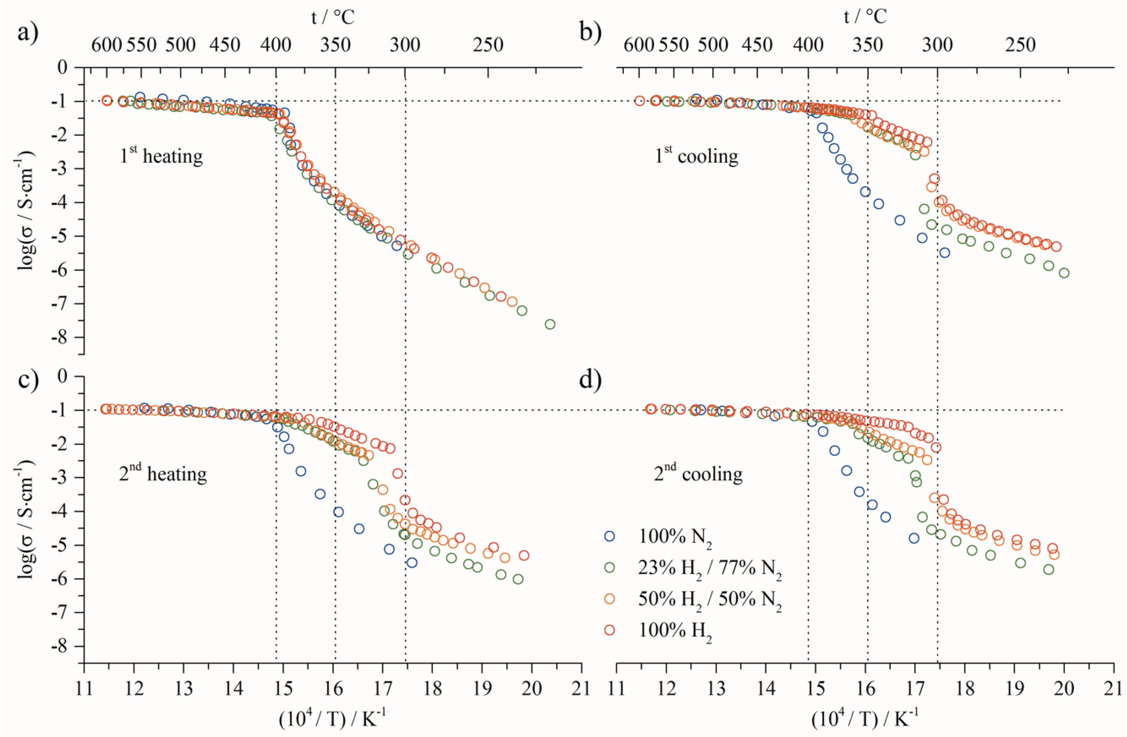
| Dry reducing | N2/H2 | 77/23 | Figures 2–4 |
| 50/50 | Figure 4 | ||
| 0/100 | |||
| Wet reducing | N2/H2/H2O | (77/23) hum. 20% | Figure 6b |
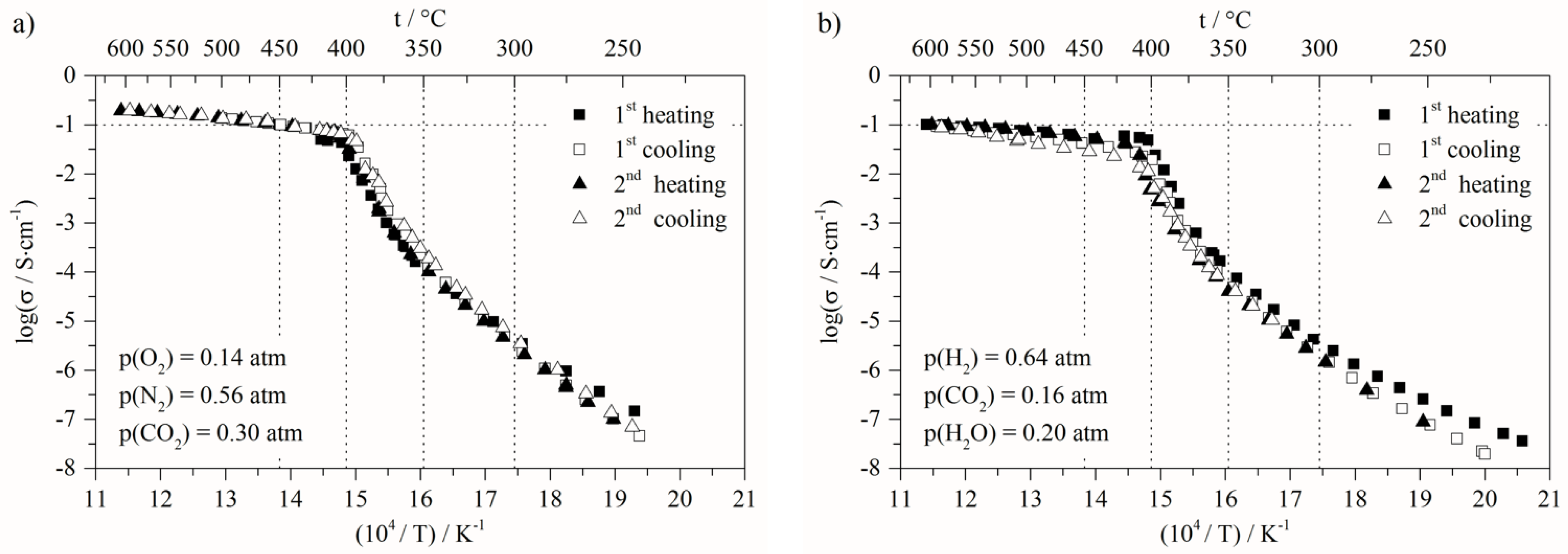
| MCFC oxidizing | N2/O2/CO2 | 56/14/30 | Figure 7a |
| MCFC reducing | H2/CO2/H2O | 64/16/20 | Figure 7b |
| SDC-LiNaK | tonset, °C | |||
|---|---|---|---|---|
| Gas Mixture | H2, %vol. in Ar | |||
| 0 | 23 | 50 | ||
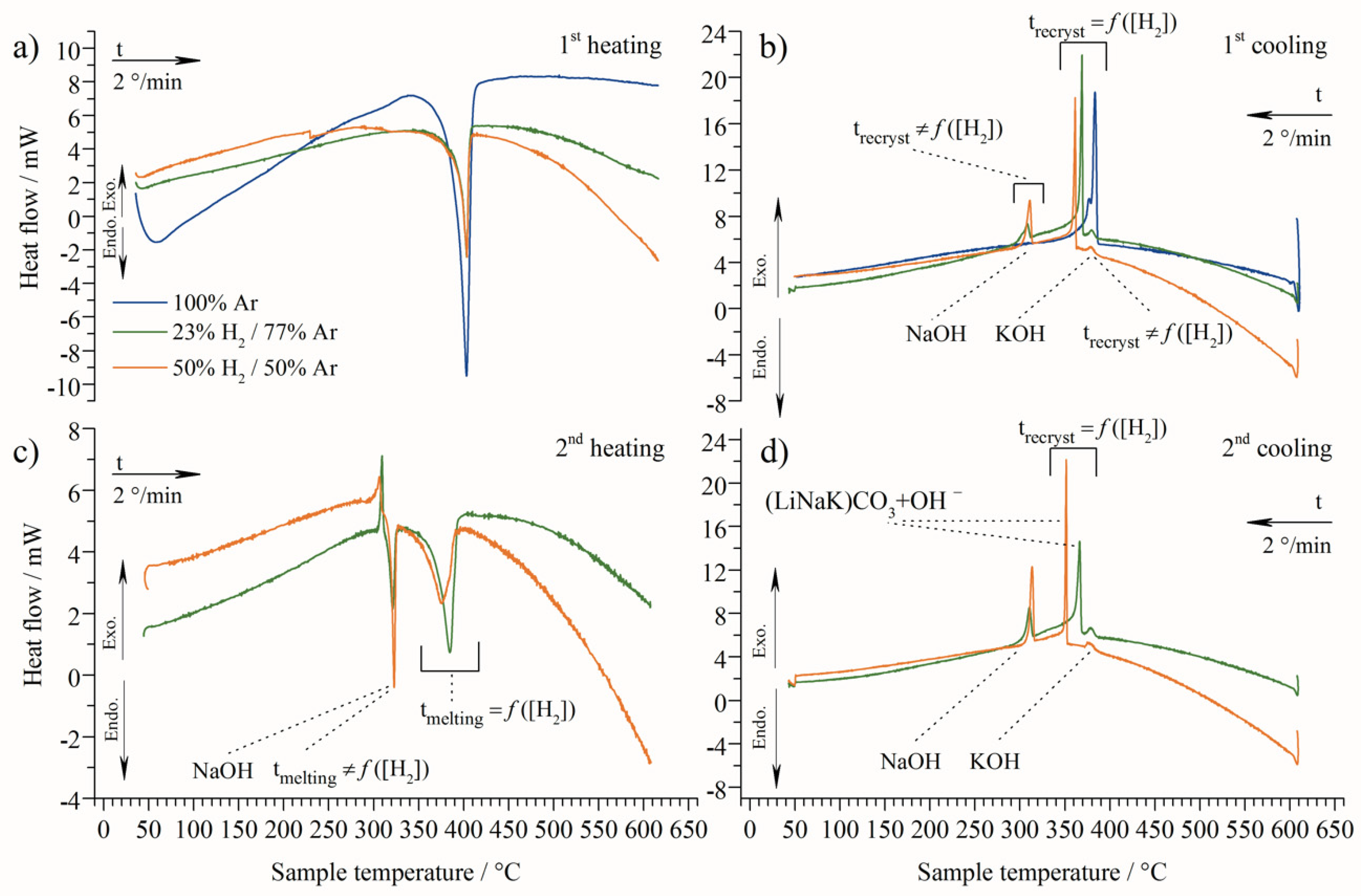
| 1st cycle | Heating | 387 | 389 | 389 |
| Cooling | 385 | 379 | 380 | |
| 377 | 365 | 358 | ||
| - | 307 | 309 | ||
| 2nd cycle | Heating | - | 302 (exo) | 297 (exo) |
| 313 | 315 | |||
| 362 | 354 | |||
| Cooling | - | 379 | 378 | |
| 363 | 347 | |||
| 309 | 311 | |||
Publisher’s Note: MDPI stays neutral with regard to jurisdictional claims in published maps and institutional affiliations. |
© 2022 by the authors. Licensee MDPI, Basel, Switzerland. This article is an open access article distributed under the terms and conditions of the Creative Commons Attribution (CC BY) license (https://creativecommons.org/licenses/by/4.0/).
Share and Cite
Grishin, A.; Ben Osman, M.; Meskine, H.; Albin, V.; Lair, V.; Cassir, M.; Ringuedé, A. Deeper Understanding of Ternary Eutectic Carbonates/Ceria-Based Oxide Composite Electrolyte through Thermal Cycling. Energies 2022, 15, 2688. https://doi.org/10.3390/en15072688
Grishin A, Ben Osman M, Meskine H, Albin V, Lair V, Cassir M, Ringuedé A. Deeper Understanding of Ternary Eutectic Carbonates/Ceria-Based Oxide Composite Electrolyte through Thermal Cycling. Energies. 2022; 15(7):2688. https://doi.org/10.3390/en15072688
Chicago/Turabian StyleGrishin, André, Manel Ben Osman, Haïtam Meskine, Valérie Albin, Virginie Lair, Michel Cassir, and Armelle Ringuedé. 2022. "Deeper Understanding of Ternary Eutectic Carbonates/Ceria-Based Oxide Composite Electrolyte through Thermal Cycling" Energies 15, no. 7: 2688. https://doi.org/10.3390/en15072688