Article

Thermal Analysis of Dual-Axis-Direction Hybrid Excitation Generator for Electric Vehicles

College of Automation Engineering, Nanjing University of Aeronautics and Astronautics, Nanjing 211106, China
*
Author to whom correspondence should be addressed.
Energies 2022, 15(9), 3011; https://doi.org/10.3390/en15093011
Submission received: 26 March 2022 / Revised: 14 April 2022 / Accepted: 14 April 2022 / Published: 20 April 2022

Abstract

:
Electric vehicle (EV) generators have characteristics of small volume and high power density, which leads to high temperature rise. The temperature rise will directly influence the service life and reliability of the generator, so thermal analysis of EV generators is necessary in machine design. This paper carries out thermal analysis of a dual-axis-direction hybrid excitation generator (DHEG) used in EVs. The lumped parameter thermal network (LPTN) method is used to build the three-dimensional thermal model of DHEG. Compared with finite element analysis, LPTN can significantly reduce the simulation time while ensuring a good accuracy. Then, the influence of heat dissipation rib on DHEG temperature rise is studied. The results prove that adding heat dissipation rib on the enclosure surface can effectively reduce the maximum temperature of DHEG.

1. Introduction

Hybrid excitation machines (HEMs) have been widely used in electric vehicles (EVs) due to their flexible voltage regulation performance [1,2]. As the space in EV where HEMs are placed is limited, designing HEMs with high power density becomes important [2,3]. The power density of HEMs can be improved by machine optimization design and control algorithm [3,4,5,6,7]. However, the space in EV is limited, so it is difficult to dissipate heat, resulting in the temperature rise of HEM, and the temperature rise will influence the service life and reliability of HEM. Additionally, the NdFeB-based permanent magnets (PMs) are generally prone to demagnetization at elevated temperatures [8]. Therefore, the thermal analysis of HEM in EVs is necessary in machine design.
At present, there are three main methods used in thermal analysis: finite element analysis (FEA), computational fluid dynamics (CFD), and lumped parameter thermal network (LPTN). Many researchers have been endeavoring to improve the accuracy of these methods. A partitioned stator hybrid excitation axial flux switching PM motor for in-wheel traction applications is proposed; the electromagnetic performances, anti-demagnetization capability, flux regulation performance and thermal analysis are investigated [9]. An outer rotor claw pole PM synchronous motor is proposed, and a complete multi-physics FEA including the electromagnetic and thermal analysis are presented [10]. To verify the heat dissipation reliability of a hybrid excitation flux-switching machine, FEA is used to develop a thermal simulation method of electromagnetic-fluid-thermal coupling [11]. A high-torque modular HEM for EV propulsion applications is proposed; the rotor loss is optimized and thermal stress is calculated and compared with the FEA results [12]. A detailed FEA-based design procedure of the forced water cooling system for a claw pole transverse flux PM motor is presented [13]. An accuracy improved LPTN for vehicle claw-pole alternator by calibrating forced convection coefficients based on experimental results is proposed [14]. The influence of stator temperature on the acoustic noise of a claw-pole alternator is studied, and the resonant frequencies of the wound stator at different temperatures can be predicted [15]. A combined three-dimensional (3D) magnetic and thermal network method is proposed to obtain the performance of PM claw pole machine. The proposed method has the merits of close magnetothermal coupling and fast calculating speed [16]. Thermal model of a claw pole generator using a method combing FEA with experiment is determined [17]. A simplified LPTN for thermal analysis of a claw-pole machine is built, and the thermal coefficients are obtained by analysis of CFD and FEA [18].
The above three thermal analysis methods (FEA, CFD, and LPTN) have their own advantages and disadvantages. FEM can obtain the distribution of temperature field in the machine and the specific temperature and location, but it has the drawbacks of long calculation time and difficult to deal with boundary conditions. By coupling the temperature field and fluid field of the machine, CFD can accurately calculate the heat transfer coefficient, fluid flow state, and temperature field distribution of each contact surface in the machine, but it has high requirements for mesh quality and computer resource allocation, and the calculation process is complex and time-consuming. LPTN represents each structural part of the machine with lumped parameters such as interconnected thermal resistance and thermal capacitance, which simplifies its calculation model and can quickly obtain the temperature of each node. However, the temperature of a node obtained by LPTN is the average temperature of a structural part of the machine. Compared with FEM and CFD, LPTN has been widely used in thermal analysis because of its short calculation time and simple calculation model.
In this article, a DHEG for EV application is used for thermal analysis. Based on the structural characteristics and cooling conditions of DHEG, the LPTN model is established, and the temperature of each component under 3000 rpm condition is analyzed. On this basis, the effect of heat dissipation rib on DHEG is analyzed. The results show that the temperature is effectively reduced by using heat dissipation rib on the enclosure.

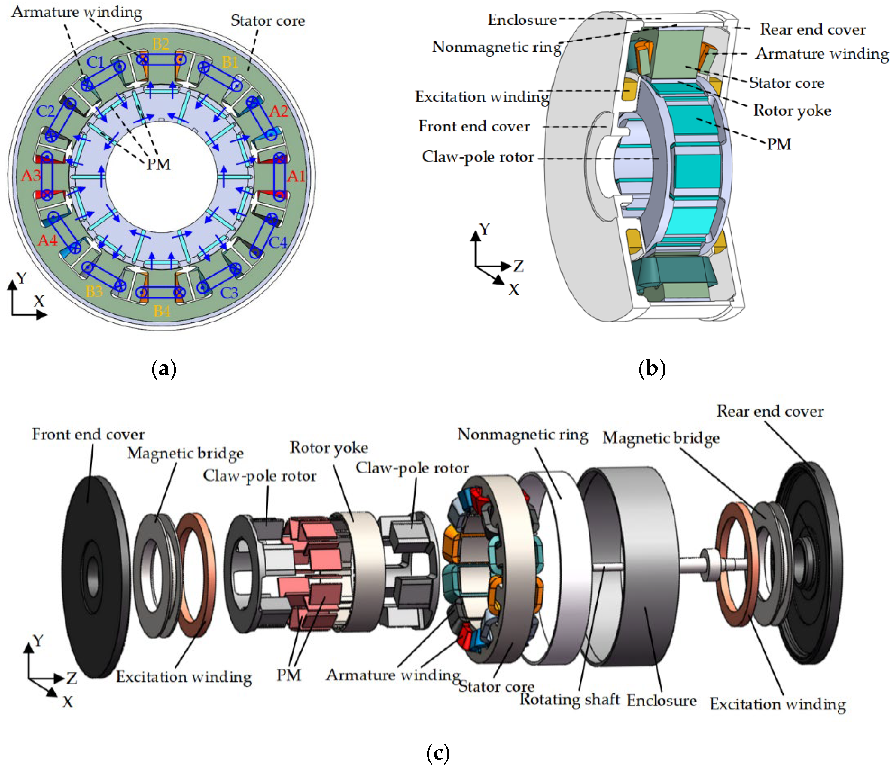
2. Machine Configuration and Parameters

The configuration of the proposed DHEG is shown in Figure 1 and the dimension parameters of DHEG are listed in Table 1. The main components of DHEG are stator core, claw-pole rotor, nonmagnetic ring, front and rear end covers, and enclosure. The stator core consists of silicon steel sheets, and twelve coils are wounded in stator slots. The rotor part is composed of two claw-pole rotors, PMs, and rotor yoke. PMs are sandwiched in the two claw-pole rotors, and the magnetization directions are indicated by the blue arrows. Two excitation windings are placed in front and rear end covers, respectively.

3. Thermal Analysis Modeling

3.1. Basic Law of Heat Transfer

Heat transfer is a natural phenomenon that exists almost all the time in real life. It mainly exists between two substances with unequal temperatures. The heat transfer modes are mainly divided into the following three types: heat conduction, heat convection, and heat radiation. In DHEG, the heat transfer modes are mainly heat conduction and heat convection, and the heat radiation can be ignored. Therefore, the heat conduction and heat convection will be discussed in detail.

3.1.1. Heat Conduction

There is no relative displacement ratio between the parts of an object. The heat transfer generated by the thermal movement of micro particles such as molecules, atoms, and free electrons is called heat conduction. The heat conduction rate can be expressed as:
q 1 = Q S = λ d T d n
where Q is heat flow; S is the heat transfer area; λ is the heat conduction coefficient of the material. d T / d n is the temperature gradient.

3.1.2. Heat Convection

Heat convection is a special way of heat transfer. It only occurs between flowing objects. Its working principle is to realize heat transfer in space by relying on flowing medium. Different from the fact that there is no relative displacement when heat conduction occurs, there will be macro relative displacement when heat convection occurs. When fluids with different temperatures mix with each other, heat will transfer from high-temperature fluid to low-temperature fluid. It should be noted that the heat transfer between fluids is bound to be accompanied by the thermal movement of micro particles, so the heat conduction is also carried out at the same time in the process of heat convection. The heat convection rate can be expressed as:
q 2 = h s S ( T s T r )
where h s is the heat convection coefficient; T s is the surface temperature of solid medium; T r is the temperature of the fluid medium.

3.2. Establishment of 3D Equivalent Thermal Network Model

In this section, the LPTN method will be used to build the 3D equivalent thermal network model of DHEG. According to the different material properties of each component in DHEG, the solution region of the analytical model is divided. According to different heat transfer conditions and corresponding thermal network model, the corresponding thermal resistance is deduced. Finally, a complete 3D thermal network model of DHEG is established. In order to speed up the calculation, the following assumptions are made before modeling:
  • The heat source loss of each component in DHEG is evenly distributed;
  • Ignoring the skin effect in DHEG;
  • The DHEG is symmetrical along the center line of the rotating shaft, and the calculation area of the internal temperature field is also symmetrical;
  • The heat conduction coefficient and temperature of the air inside DHEG are the same;
  • For the components of hollow cylinder in DHEG, only axial and radial heat transfer is considered, the circumferential heat transfer is not considered.

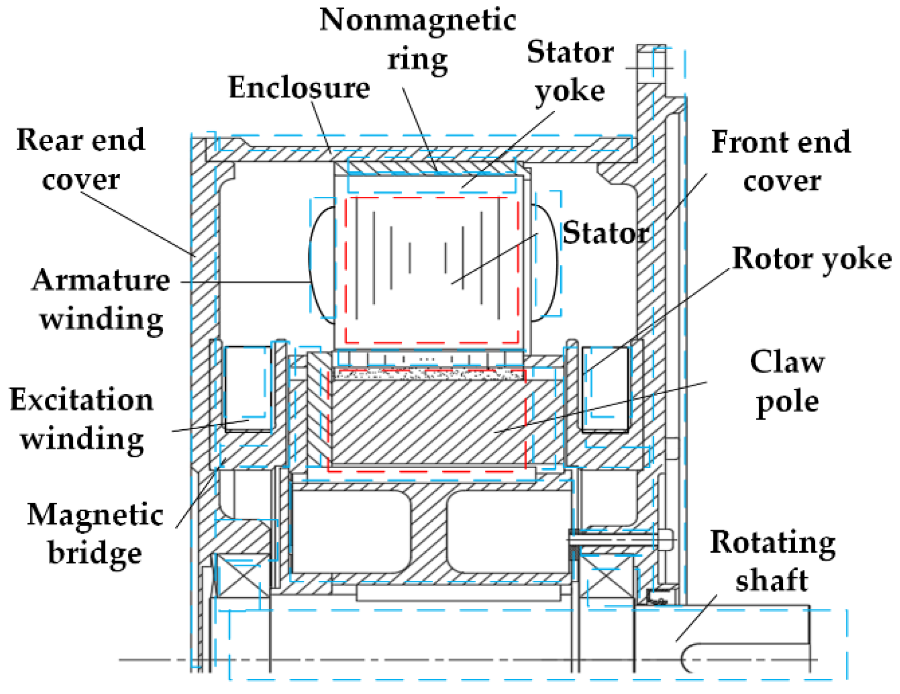
3.2.1. Solving Region Division

There are many heat sources in DHEG and the heat dissipation paths are complex, so the heat dissipations in different areas under the condition of natural heat dissipation need to be considered. At the same time, the temperature field solution area of DHEG is composed of heat conduction area and heat convection area. The heat conduction area can be divided into: rotating shaft structure area, rotor structure area, magnetic bridge area, stator area, end cover area, and enclosure area, which is shown in Figure 2. Since DHEG is sealed inside, it is assumed that there is no heat convection area inside DHEG; only the heat conduction of air inside DHEG is considered, and the heat convection only occurs on the outer surface of DHEG.

3.2.2. Calculation of Thermal Resistance in Solving Region

It is very important to accurately calculate the thermal resistance of each component in the thermal network model when using LPTN method. At present, there are two models to calculate the thermal resistance: hollow cylinder heat conduction model and cuboid heat conduction model. The hollow cylinder heat conduction model is proposed by Mellor, and the structure of both conduction models are shown in Figure 3.
In Equation (3), r 1 , r 2 are the inner diameter and outer diameter of the hollow cylinder, respectively; T a l , T a r , T r o , T r i are the temperatures of each surface on the hollow cylinder, respectively; R a 1 , R a 2 , R a 3 are the thermal resistances of axial heat conduction; R r 1 , R r 2 , R r 3 are the thermal resistances of radial heat conduction; T m is the average temperature of the hollow cylinder; p c y is the power loss generated in the hollow cylinder.
The axial heat conduction thermal resistances R a 1 and R a 2 can be expressed as:
R a 1 = R a 2 = h 2 π k a ( r 2 2 r 1 2 )
where k a is the axial thermal conductivity of the hollow cylinder.
The axial heat conduction thermal resistances R a 3 can be expressed as:
R a 3 = h 6 π k a ( r 2 2 r 1 2 )
The radial heat conduction thermal resistances R r 1 , R r 2 , R r 3 can be expressed as:
R r 1 = 1 4 π k r h [ 1 2 r 1 2 ln ( r 2 r 1 ) ( r 2 2 r 1 2 ) ]
R r 2 = 1 4 π k r h [ 2 r 2 2 ln ( r 1 r 2 ) ( r 1 2 r 2 2 ) 1 ]
R r 3 = 1 8 π k r h ( r 2 2 r 1 2 ) [ ( r 1 2 + r 2 2 ) 4 r 1 2 r 2 2 ln ( r 2 r 1 ) ( r 2 2 r 1 2 ) ]
where k r is the radial thermal conductivity of the hollow cylinder.
According to the shape of each component in DHEG, the air gap inside the rotating shaft, rotor claw pole yoke, winding, magnetic bridge, end cover, stator yoke, and enclosure can be approximated as hollow cylinder. Only radial heat conduction and axial heat conduction need to be considered in the calculation of thermal resistances in these areas.
Unlike the hollow cylinder, which only needs to consider four surfaces, the temperature corresponding to six surfaces in cuboid heat conduction model needs to be considered. Therefore, the structure and equivalent thermal network model of cuboid heat conduction model are shown in Figure 4.
Where w , l , h are the length of the cuboid along the x-axis, y-axis, and z-axis, respectively. T x 1 , T x 2 , T y 1 , T y 2 , T z 1 , T z 2 are the temperature of six surfaces in cuboid, respectively. R x 1 , R x 2 , R y 1 , R y 2 , R z 1 , R z 2 are the thermal resistance of six surfaces in cuboid, respectively. T m is the average temperature of the cuboid.
The thermal resistance along the x-axis in the cuboid R x 1 , R x 2 can be expressed as:
R x 1 = R x 2 = w 2 k x h l
where k x is the thermal conductivity of the cuboid along x-axis.
The thermal resistance along the y-axis in the cuboid R y 1 , R y 2 can be expressed as:
R y 1 = R y 2 = l 2 k y h w
where k y is the thermal conductivity of the cuboid along y-axis.
The thermal resistance along the z-axis in the cuboid R z 1 , R z 2 can be expressed as:
R z 1 = R z 2 = h 2 k z l w
where k z is the thermal conductivity of the cuboid along z-axis.
The PM, stator teeth, winding end, and rotor claw pole teeth can be approximated as cuboid.
The thermal resistance of heat convection can be expressed as:
R c v = 1 α k S
where α k is heat dissipation coefficient.
There are different material components in DHEG, such as stator teeth, slot insulation, copper wire, etc., which form a series composite structure. In the composite structure, the total thermal resistance from material component 1 to material component 3 R all is expressed as:
R all = L 1 k 1 S + L 2 k 2 S + L 3 k 3 S

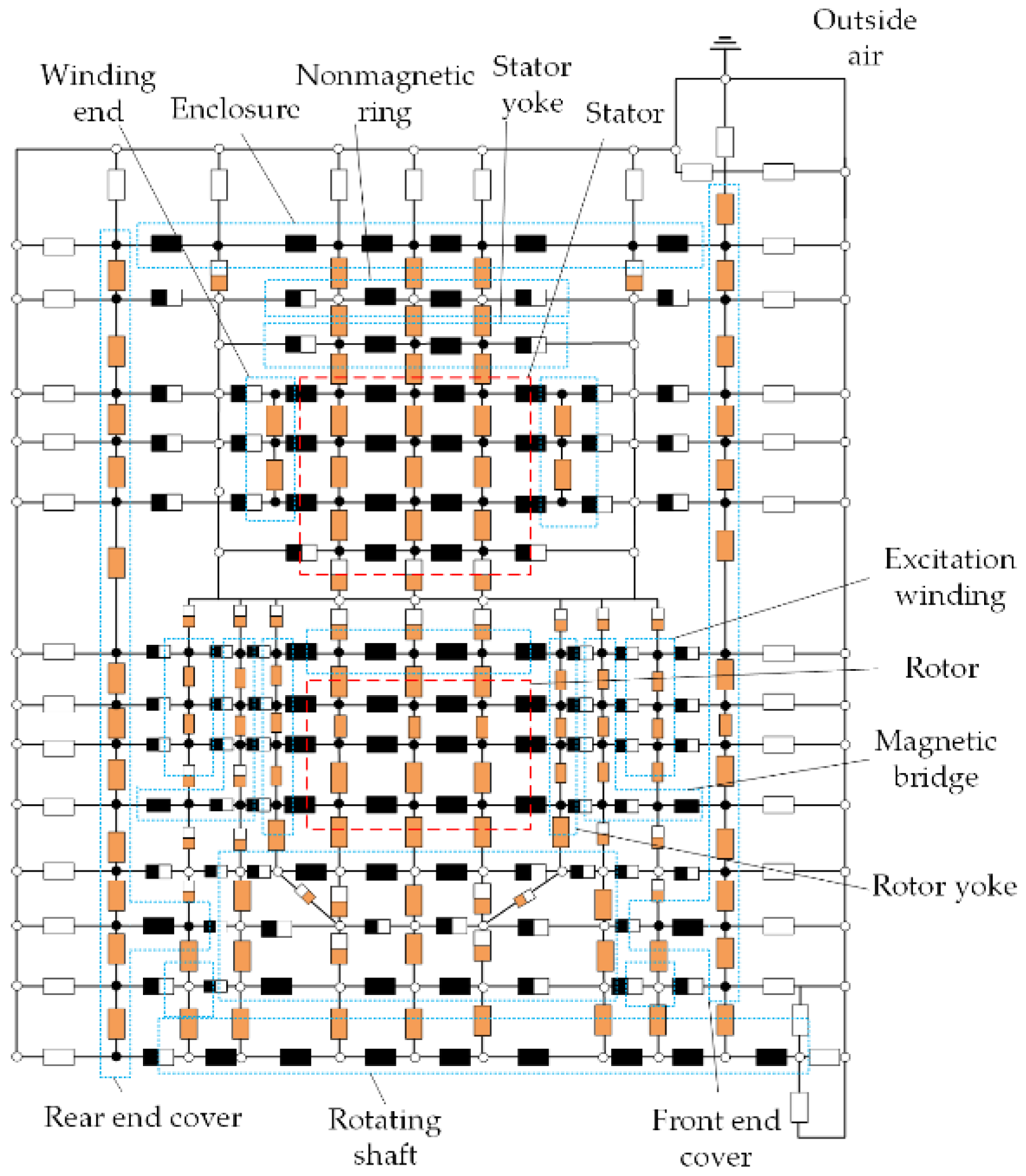
3.2.3. Establishment of Thermal Network Model

The thermal models of different structures are introduced above. When modeling, it is necessary to model the hollow cylinder structure and cuboid structure respectively. Since the stator part and rotor part of DHEG are mostly composed of cuboid elements, the stator part and rotor part can be modeled according to the cuboid heat conduction model.
The thermal network model of DHEG stator part is shown in Figure 5. The gray rectangle shown in the figure represents the transverse conduction thermal resistance, the orange rectangle represents the radial conduction thermal resistance, and the two-color rectangle represents the conduction thermal resistance of the corresponding composite structure. The armature winding is equivalent in the derivation process, and the specific equivalent method will be introduced in detail below. The black solid circle represents the temperature node with loss heat source injection, and the hollow circle represents the temperature node without loss heat source injection. For convenience, only one twelfth of the model is established, and the rest is consistent with it.
The thermal network model of DHEG rotor part is shown in Figure 6. The rotor is divided radially along the axis center to show the structure of rotor claw pole teeth and PM. It should be noted that the rotor claw pole and the rotating shaft structure are connected by interference fit, so the air gap convection between them can be ignored. Since the PM is embedded in the rotor with potting glue, the convection problem in the air gap can also be ignored. At the same time, three-layer equivalent thermal network nodes are adopted for components with large structural size in the modeling process. The middle node is used to observe the temperature inside the component, and the nodes on both sides are used to observe the temperature change after heat transfer between both ends of the component and other material components.
The complete 3D thermal network of DHEG is shown in Figure 7. The equivalent thermal network models of stator and rotor part are simplified as one temperature node and one thermal resistance. The simplified equivalent thermal network model of stator and rotor part has been marked by red dotted line in Figure 7. Other parts of DHEG are marked with blue dot boxes. The black rectangle represents the axial conduction thermal resistance, the orange rectangle represents the radial conduction thermal resistance, the two-color rectangle represents the mixed conduction thermal resistance in the corresponding direction, and the white rectangle represents the convection thermal resistance. The black solid circle represents the temperature node with loss heat source injection, and the hollow circle represents the temperature node without loss heat source injection.

3.3. Solution of 3D Equivalent Thermal Network Model

3.3.1. Calculation of Thermal Conductivity and Heat Dissipation Coefficient

The heat generated in the coil can be transferred to the outside air in the following ways: (1) The coil will first transfer the heat to the stator core in the form of heat conduction, and then the stator core will transfer the heat to the outside air in the form of heat convection; (2) the coil directly transfers heat to the outside air by means of heat convection.
The thermal conductivity and heat dissipation coefficients of various materials can be calculated as followed.
(1)
Thermal conductivity of stator and rotor cores
Silicon steel sheet is generally selected as the core material of stator and rotor cores, but the thermal conductivity of silicon steel sheet will be different in its axial and radial direction, so the expressions of axial and radial thermal conductivity are listed as:
λ axi = δ s i + δ 0 δ s i λ s i + δ 0 λ 0 = 1 K s i λ s i + 1 K s i λ 0
λ rad = δ s i λ s i + δ 0 λ 0 δ s i + δ 0 = K s i λ s i + ( 1 K s i ) λ 0
where δ s i is the thickness of silicon steel sheet; δ 0 is the length of the insulating medium; λ s i is the thermal conductivity of silicon steel sheet; λ 0 is the thermal conductivity of insulating material; K s i is the lamination coefficient.
(2)
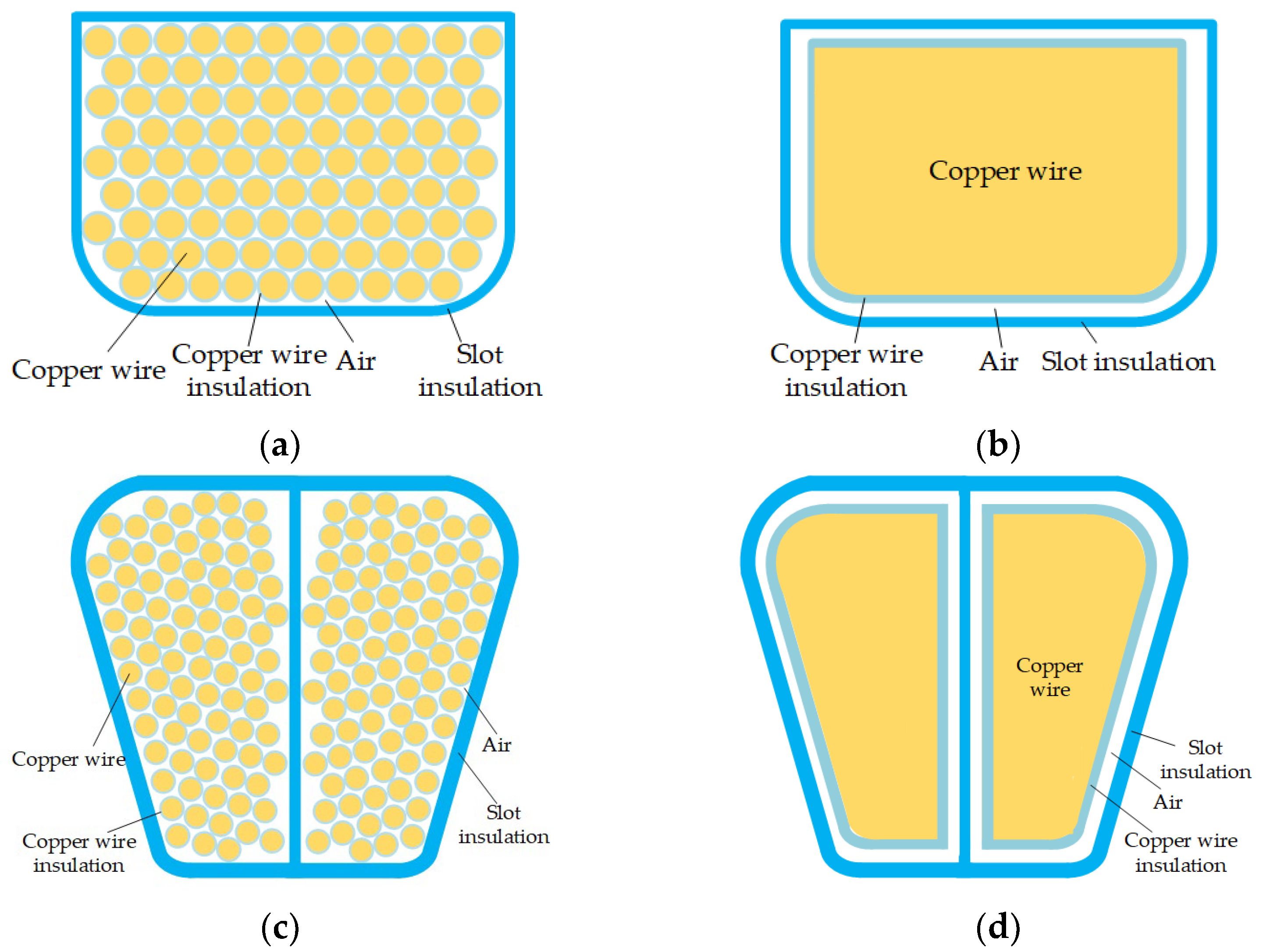
Thermal conductivity of winding
It is difficult to calculate the thermal conductivity of the winding after winding the copper wire. Therefore, for the convenience of calculation, the temperature difference between windings is ignored, and the insulation layer is assumed to be evenly distributed, as shown in Figure 8. The equivalent thermal conductivity of winding can be expressed as:
λ eq 1 = δ Cu + δ cmp + δ air + δ smp δ Cu λ Cu + δ cmp λ cmp + δ air λ air + δ smp λ smp
where λ Cu is the thermal conductivity of copper wire; λ cmp is the thermal conductivity of copper wire insulation; λ air is the thermal conductivity of air; λ smp is the thermal conductivity of the slot insulation layer; δ Cu is the equivalent thickness of copper wire; δ cmp is the equivalent thickness of copper wire insulation; δ air is the equivalent thickness of air; δ smp is the equivalent thickness of slot insulation.
(3)
Equivalent thermal conductivity of air gap
The heat transfer of DHEG rotor is mainly realized by the flow of fluid in air gap. When the rotor runs at high speed, it drives the fluid in the air gap to flow. The movement of the fluid is also accompanied by the movement of micro particles. The heat of the rotor is transferred to the stator through the joint action of heat convection and heat conduction of the fluid medium in the air gap. Therefore, the thermal conductivity of the DHEG air gap is treated in an equivalent way, the fluid medium flowing in the air gap is equivalent to a static fluid medium, and the corresponding thermal conductivity is set to ensure that the heat transmitted by the stator and rotor in unit time remains unchanged after equivalence. The equivalent thermal conductivity of air gap can be expressed as:
λ eq 2 = 0.23 λ air β ( g m a i n r r y 2 ) 0.25 Re 0.5
where λ air is the thermal conductivity of the fluid medium in the air gap; β is the empirical coefficient, usually 1.15~1.25, Re is Reynolds number.
(4)
Determination of heat dissipation coefficient
The temperature distribution of DHEG is determined by the heat conduction coefficient and the heat dissipation coefficient of the enclosure. The accuracy of temperature field distribution can be effectively improved by selecting an accurate heat dissipation coefficient.
The heat dissipation coefficient of stator end and rotor end can be expressed as:
α s = 1 + 0.04 v r 0.045
where v r is the linear speed of the outer diameter of the rotor.
The heat dissipation coefficient of enclosure can be expressed as:
α e = 14 ( 1 + 0.5 v e ) 3 T e 25
where v e is the flow speed of air outside the enclosure, T e is the temperature of air outside the enclosure.
(5)
Determination of heat capacity coefficient
Heat capacity is the relationship between the temperature change of the object and the heat flow received in unit time, and can be expressed as:
C 0 = d Q d T
where the heat capacity per unit mass of an object is called the specific heat capacity.
The components required for DHEG temperature field analysis and their corresponding material parameters, such as density, specific heat capacity, and thermal conductivity are shown in Table 2.

3.3.2. Heat Balance Equation

The heat transfer formula of each node in the 3D thermal network model in DHEG is:
P i j i ( T i T j ) G i j = C i d T i d t
where P i is the heat generated at the node i ; T i , T j are the temperatures at nodes i , j , respectively; G i j is the thermal conductance between nodes i and j ; C i is the heat capacity coefficient at node i .
When DHEG reaches the thermal steady state, the heat balance equation of its thermal network model can be obtained according to Kirchhoff’s law in the circuit:
[ G ] [ T ] = [ P ]
where [ G ] is the node thermal admittance matrix; [ T ] is the node temperature rise matrix; [ P ] is the node heat conduction rate matrix of thermal network.

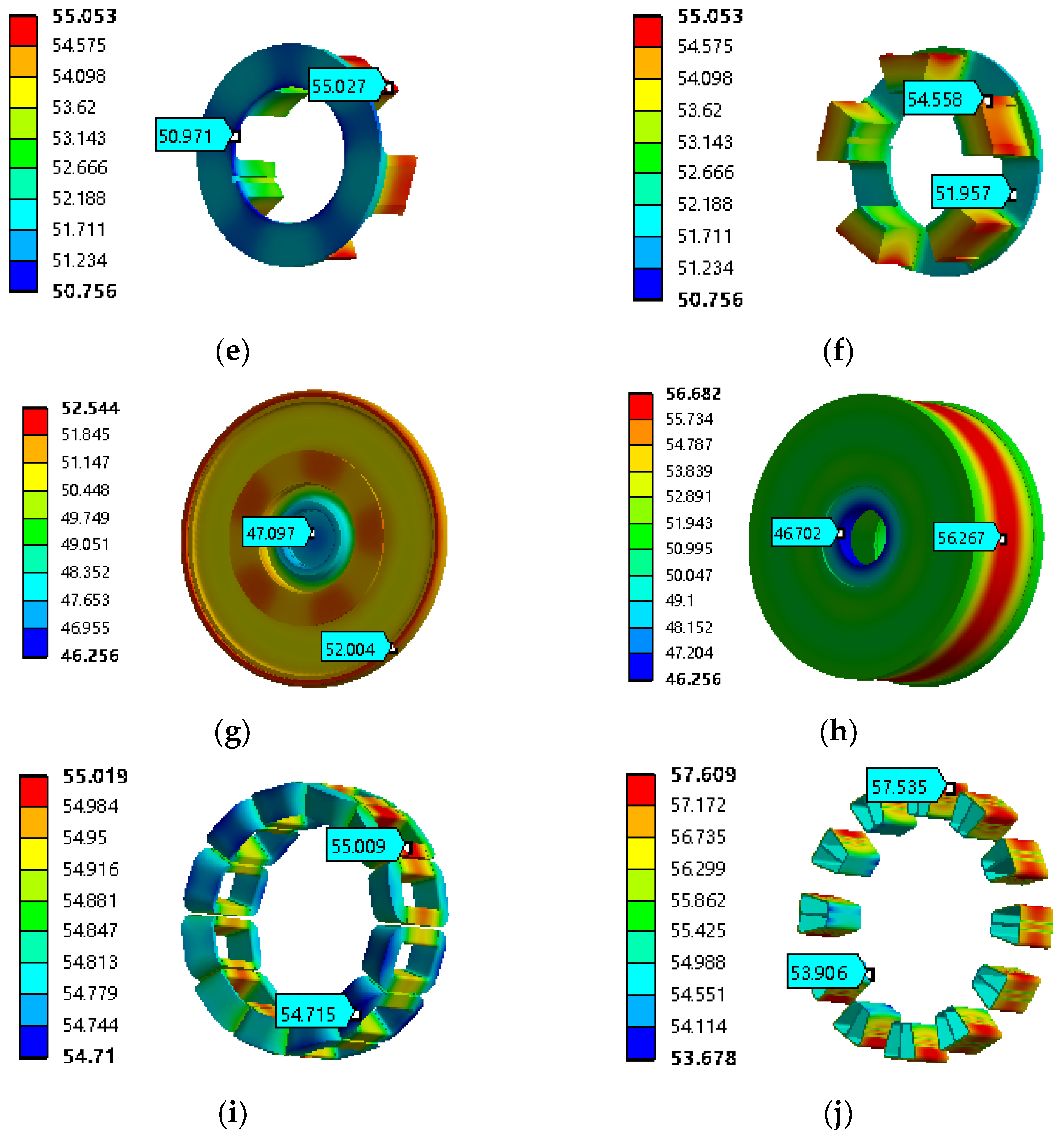
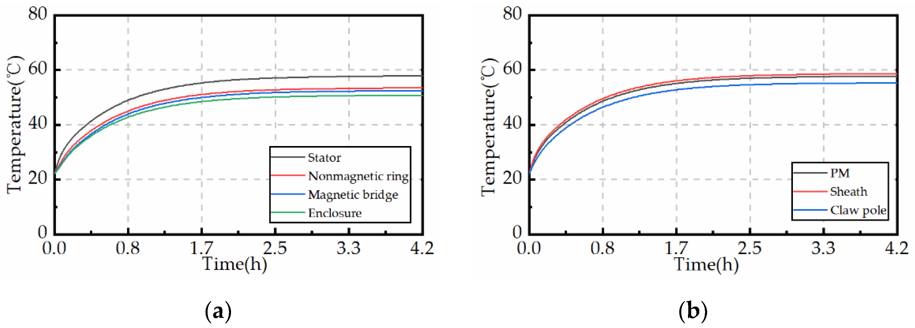
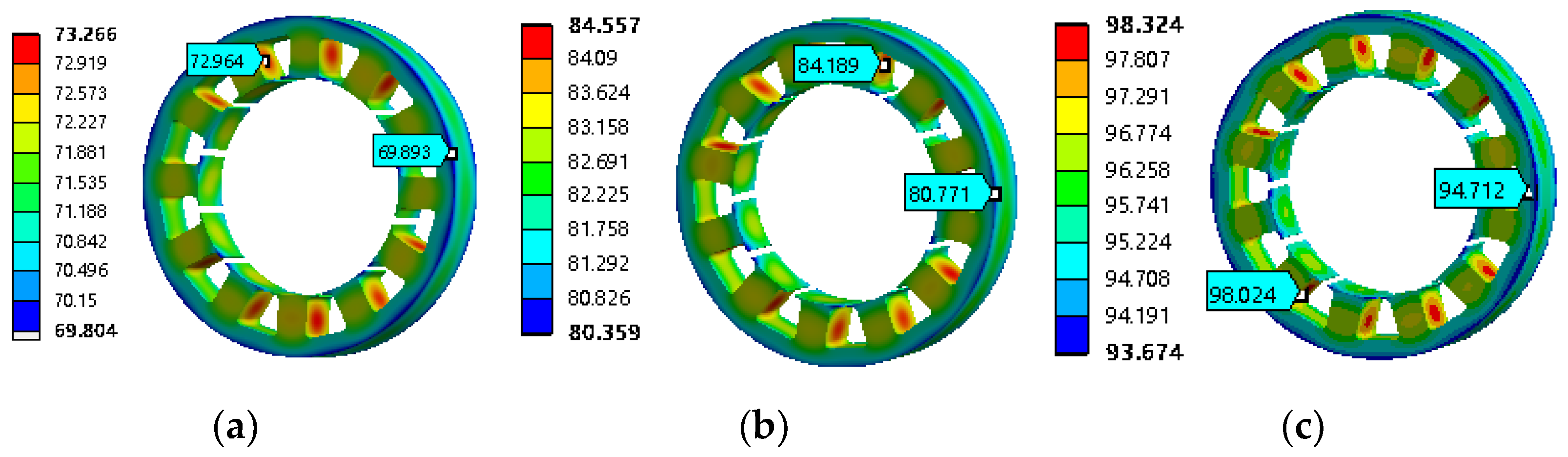
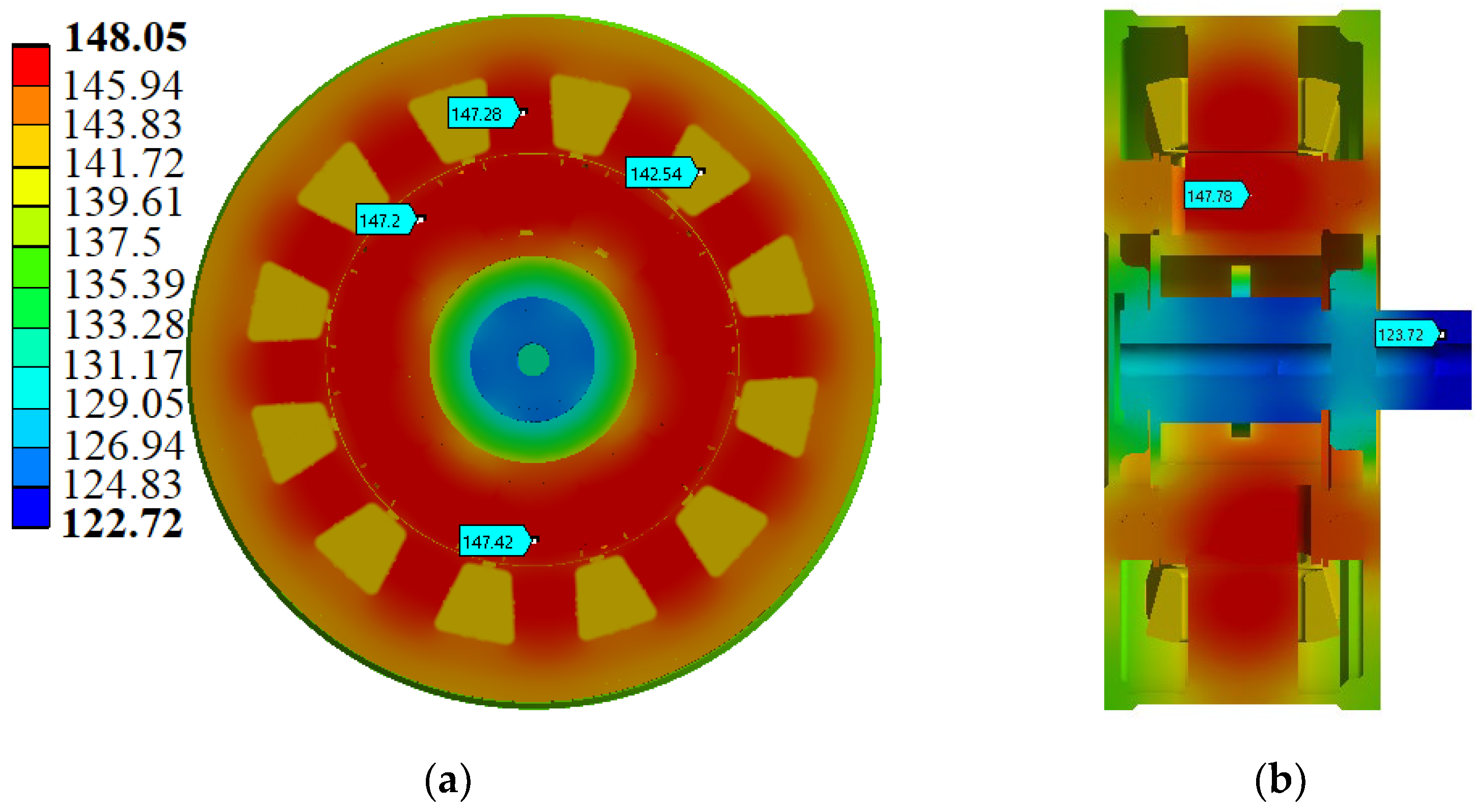
3.3.3. Temperature Distribution of DHEG

According to the 3D thermal network model given above, the thermal analysis of DHEG under the rated speed of 3000 rpm, excitation current of 4 A and full load is carried out by using MATLAB software, and the ambient temperature is set to 25 °C. The DHEG thermal network model calculation flow by MATLAB software is shown in Figure 9. The thermal conductivity of the material used is an empirical value, so it will not change with the change of temperature, resulting in a certain error relative to the actual value in the calculation of DHEG temperature. Since the error will increase with the increase of temperature, only the ambient temperature of 25 °C is calculated here, and the case of 75 °C will be analyzed in FEA.
The temperature of each node in DHEG thermal network model is obtained, as shown in Figure 10. For convenience, the axial profile of stator and rotor is placed in the thermal network, as shown in the red dotted box. The temperature distribution of stator and rotor teeth is at the center line. Due to the good heat dissipation effect at the ends of stator and rotor teeth, the temperature is lower than that at the middle position, but higher than that at the ends of windings. The position not marked with temperature in Figure 10 is the temperature of the air in DHEG. It can be seen from Figure 10 that the high temperature point inside DHEG is mainly concentrated on the stator and rotor core, and its temperature exceeds 100 °C, while the temperature of armature winding and excitation winding is relatively low, about 96 °C. Since the DHEG prototype adopts winding insulation that can withstand 200 °C, and the PM adopts NdFeB material that can withstand 150 °C, DHEG has no risk of damage and demagnetization in this state.

3.4. 3D FEA Temperature Field Calculation

Due to the complex internal heat transfer of DHEG, the thermal model of DHEG needs to be simplified accordingly, and the following assumptions are made during simplification:
(1)
The thermal conductivity and heat dissipation coefficient of DHEG material do not change with the change of temperature.
(2)
The initial temperature of DHEG is the same as the ambient temperature.
(3)
There is no temperature difference between the windings, the winding is calculated as one heat conductor, and the insulation between the windings is calculated as another heat conductor.
(4)
The heat dissipation on the stator surface, enclosure surface, and rotor surface is uniform, so the heat dissipation coefficient can be taken as their average value.

3.4.1. Establishment of 3D FEA Thermal Model

The temperature field analysis 3D mesh model of DHEG is shown in Figure 11. DHEG is a kind of multi heat source structure, the loss is mainly from the stator core and the winding. It is necessary to subdivide the stator core and armature winding more finely. The maximum division length of stator core and winding is set to 2 mm. The maximum division length of other parts in DHEG is set to 5 mm. The number of mesh element in stator core and armature winding is 500,000, while the total number of mesh element in DHEG is 780,000.
The temperature field analysis model includes stator, rotors’ rotating shafts, equivalent winding, and equivalent air gap. In order to simplify the calculation, the winding coil is equivalent to a cuboid of the same volume, the insulation between windings is equivalent to a conductor, and the flowing air gap between stator and rotor is replaced by a static equivalent air gap.

3.4.2. Temperature Field Distribution of DHEG under Natural Cooling Condition

The model is established according to the above analysis, and the temperature field of DHEG is simulated and analyzed. Due to the DHEG working in EV, the natural cooling condition is used to analyze the generator. The loss increases gradually with the increase of speed. Therefore, the DHEG temperature rise at 3000 rpm is analyzed. The DHEG operates at full load, the excitation current is 0, and the ambient temperature is set to 25 °C. The temperature distribution of DHEG under this working condition is shown in Figure 12.
The stator teeth are wrapped by winding, and the heat in the stator teeth is generated by the stator and the winding. Therefore, the temperature of the stator teeth is relatively high, and the maximum temperature of the stator appears at the stator teeth, which is 57.609 °C. The temperature of the stator yoke is relatively small, because the heat can be quickly transferred to the enclosure through the nonmagnetic ring and dissipated into the air. The maximum temperature of winding is 55.009 °C, and the temperature at the end of the winding in Figure 12i is slightly lower than that in the middle of the winding, because both ends of the winding are directly exposed to the air for heat dissipation, while the middle position of the winding is in the stator core, and the loss of the stator core is greater than the copper loss of the armature winding.
The temperature of DHEG varies in different components. As shown in Figure 13, the temperature of the stator core is higher than that of other parts, while the temperature of the nonmagnetic ring, magnetic bridge, and enclosure is lower because they are closer to the outside. The temperature of PM and sheath is close, as the claw pole can rely on the rotating shaft for heat dissipation, therefore, the temperature can be lower than that of the PM and sheath.
In addition to the magnetic field provided by PM, there is also the magnetic field provided by the excitation winding. Therefore, it is necessary to consider the influence of the excitation winding on DHEG temperature when different excitation currents are applied. Under the conditions of 3000 rpm and full load, the temperature rise of DHEG is analyzed at the excitation current 1 A, 2 A, and 4 A, respectively.
The steady-state temperature distribution of DHEG stator core at 3000 rpm is shown in Figure 14. When the excitation current is 1 A, 2 A, and 4 A, respectively, the maximum temperature is 72.964 °C, 84.189 °C, and 98.024 °C, respectively. When the excitation current increases, the loss of stator core increases, which leads to the increase of stator temperature.
The steady-state temperature distribution of DHEG enclosure at 3000 rpm is shown in Figure 15. When the excitation current is 1 A, 2 A, and 4 A, respectively, the maximum temperature is 70.27 °C, 81.936 °C, and 94.877 °C, respectively.
When the excitation current is 4 A, the temperature rise curve of different components in DHEG is shown in Figure 16. It can be seen from Figure 13 and Figure 16 that the temperature change trend inside DHEG is the same, and the temperature of enclosure is lower than that of the stator and rotor.
When the ambient temperature is 75 °C, the temperature change at each position in DHEG is shown in Figure 17. The temperature of the stator core and rotor reaches about 147 °C, and the winding temperature is about 142 °C, so there is no risk of damage to the winding insulation. At the same time, the temperature of PM is 147 °C, which is close to the limit value of 150 °C. Therefore, when the ambient temperature is 75 °C, it is necessary to reduce the load power of DHEG to prevent irreversible demagnetization of PM due to high temperature, or use other methods to improve the heat dissipation of DHEG, so as to reduce the internal temperature of DHEG.

3.4.3. Comparison of Temperature Field Simulation Results

In this article, the internal temperature distribution of DHEG is obtained in two ways. The calculation results of LPTN and the simulation results of FEA are compared in Table 3. It can be seen that there are certain errors in the calculation results of LPTN. The errors on the stator yoke, stator teeth, nonmagnetic ring, and enclosure exceed 5%, which is mainly due to the corresponding equivalence of the stator part, ignoring the arc chamber in the stator slot, and the stator teeth and yoke simplification. The heat dissipation at the enclosure is more complex, and few points are selected in the calculation process, which leads to a large error in the calculation result of this part.

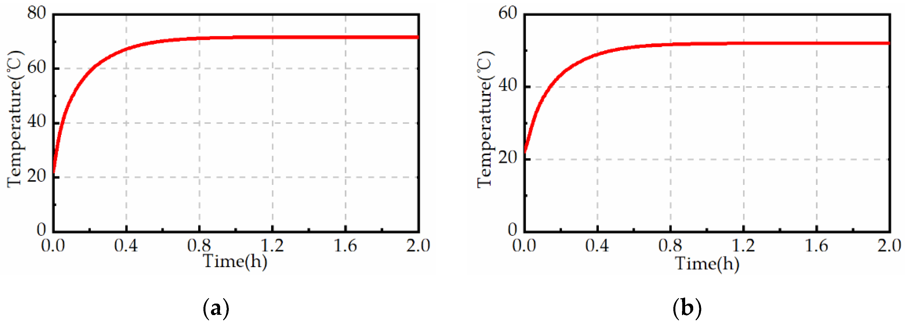
3.4.4. Experimental Results of Temperature Field

When DHEG operates to the rated speed of 3000 rpm and the excitation current is 1 A, the temperature of the rear end cover is measured with a thermography camera (FLUKE TiS60), as shown in Figure 18, and the value is about 41.2 °C. When the excitation current increases to 4 A, the temperature of the rear end cover increases to 67.7 °C, as shown in Figure 19. The comparison of the LPTN, FEA results and experiment results are shown in Table 4. It should be noted that since the ambient temperature is only 15 °C, the experimental results are significantly lower than the simulation results.
The modeling and calculation time of LPTN and FEA are listed in Table 5. It can be seen that LPTN has advantages for thermal analysis, and the results can be obtained in only 25 s. The calculation errors of LPTN and FEA are 5.6% and 3.5%, respectively. Compared with FEA, LPTN can effectively save the calculation time of temperature field simulation.

3.5. Effect of Heat Dissipation Rib on DHEG

Through the above thermal simulation analysis of DHEG when the ambient temperature is 75 °C, it can be found that the temperatures of armature winding and PM reach 142 °C and 147 °C, respectively. Although the materials used for the insulation of winding can withstand the temperature of 200 °C, the PM has a certain demagnetization risk. Therefore, the heat dissipation rib is used on the enclosure to help reduce the temperature. The ambient temperature during simulation is set to 25 °C, the excitation current is 4 A, and under full load condition. The temperature rise curve of DHEG after adding heat dissipation rib on the enclosure are obtained by simulation and are shown in Figure 20. It can be seen that the maximum temperature of stator is about 71 °C and the maximum temperature of enclosure is about 52 °C, which is lower than that without heat dissipation rib.
The temperature of stator when the ambient temperature is 25 °C, the excitation current is 4 A, and the heat dissipation rib is added to the enclosure as shown in Figure 21a. The maximum and minimum temperature are 81.239 °C and 56.076 °C, respectively, which are 17.12% and 40.79% lower than that in Figure 14c. Due to the stator yoke being closer to the enclosure, the heat dissipation is better, while the stator heat is more difficult to transfer. In Figure 21b, the maximum and minimum temperature of enclosure are 85.311 °C and 44.471 °C, respectively, which is 10.08% and 44.49% lower than that in Figure 15c. It can be seen that the temperature is effectively reduced by using heat dissipation rib on the enclosure.

4. Conclusions

This paper focuses on the thermal analysis of a DHEG used in EVs. The LPTN method is implemented to build the 3D thermal network model of DHEG. Compared with FEA, LPTN can significantly reduce the simulation time and the calculation error is acceptable. When the ambient temperature is 75 °C, the temperature of PM reaches 142 °C, which means the PM has a certain demagnetization risk. Therefore, the influence of heat dissipation rib on DHEG temperature rise is studied. It is proved that the maximum temperature of DHEG can be effectively reduced by adding heat dissipation rib on the enclosure surface.

Author Contributions

Conceptualization, S.Z.; Data curation, S.Z.; Formal analysis, Y.C.; Funding acquisition, C.L.; Investigation, Y.C., J.Y. and C.L.; Methodology, Y.C., S.Z. and J.Y.; Project administration, C.L.; Resources, C.L.; Software, S.Z. and J.Y.; Supervision, C.L.; Validation, J.Y. and C.L.; Visualization, S.Z. and J.Y.; Writing—original draft, Y.C.; Writing—review and editing, C.L. All authors have read and agreed to the published version of the manuscript.

Funding

This research was funded by the National Natural Science Foundation of China, grant number 51877108.

Conflicts of Interest

The authors declare no conflict of interest.

References

  1. Martinez-Munoz, D.; Alakula, M. Comparison between a Novel Claw-Pole Electrically Magnetized Synchronous Machine without Slip-Rings and a Permanent Magnet Machine. In Proceedings of the IEEE International Electric Machines and Drives Conference, IEEE IEMDC, Madison, WI, USA, 1–4 June 2003; pp. 1351–1356. [Google Scholar]
  2. Liu, Y.; Zhang, Z.; Wang, C.; Gao, H. Optimization and Performance Improvement of a Hybrid Excitation Synchronous Machine with Modular Magnetic-Shunting Rotor. IEEE Trans. Ind. Electron. 2020, 67, 4381–4390. [Google Scholar] [CrossRef]
  3. Shi, Z.; Sun, X.; Cai, Y.; Yang, Z.; Lei, G.; Guo, Y.; Zhu, J. Torque Analysis and Dynamic Performance Improvement of a PMSM for EVs by Skew Angle Optimization. IEEE Trans. Appl. Superconduct. 2019, 29, 1–5. [Google Scholar] [CrossRef]
  4. Huang, Y.; Zhu, J.; Guo, Y.; Hu, Q. Development of a High-Speed Claw Pole Motor with Soft Magnetic Composite Core. In Proceedings of the 2007 IEEE International Electric Machines & Drives Conference, Antalya, Turkey, 3–5 May 2007; pp. 1564–1568. [Google Scholar]
  5. Rebhi, R.; Ibala, A.; Masmoudi, A. MEC-Based Sizing of a Hybrid-Excited Claw Pole Generator. IEEE Trans. Ind. Appl. 2015, 51, 211–223. [Google Scholar] [CrossRef]
  6. Guo, Y.; Zhu, J.; Chen, J.; Jin, J. Performance Analysis of a PM Claw Pole SMC Motor with Brushless DC Control Scheme. In Proceedings of the 2006 CES/IEEE 5th International Power Electronics and Motion Control Conference, Shanghai, China, 14–16 August 2006; pp. 1–5. [Google Scholar]
  7. Sun, X.; Hu, C.; Lei, G.; Guo, Y.; Zhu, J. State Feedback Control for a PM Hub Motor Based on Gray Wolf Optimization Algorithm. IEEE Trans. Power Electron. 2020, 35, 1136–1146. [Google Scholar] [CrossRef]
  8. Leitner, S.; Kulterer, T.; Gruebler, H.; Muetze, A. Characterization of the Thermal Performances of Low-Cost Sub-Fractional Horsepower BLDC Claw-Pole Motor Designs. In Proceedings of the 2020 IEEE Energy Conversion Congress and Exposition (ECCE), Detroit, MI, USA, 11–15 October 2020; pp. 4269–4275. [Google Scholar]
  9. Xu, L.; Zhu, X.; Fan, W.; Zhang, C.; Zhang, L.; Quan, L. Comparative Analysis and Design of Partitioned Stator Hybrid Excitation Axial Flux Switching PM Motors for In-Wheel Traction Applications. IEEE Trans. Energy Convers. 2021, accepted. [Google Scholar] [CrossRef]
  10. Liang, J.; Parsapour, A.; Cosoroaba, E.; Wu, M.; Boldea, I.; Fahimi, B. A High Torque Density Outer Rotor Claw Pole Stator Permanent Magnet Synchronous Motor. In Proceedings of the 2018 IEEE Transportation Electrification Conference and Expo (ITEC), Long Beach, CA, USA, 13–15 June 2018; pp. 389–393. [Google Scholar]
  11. Ni, S.; Zhou, L.; Li, H.; Cao, R. Thermal Analysis of a Hybride Excitation Flux-Switching Motor with Water-Cooling System. In Proceedings of the 2021 IEEE 4th Student Conference on Electric Machines and Systems (SCEMS), Huzhou, China, 1–3 December 2021; pp. 1–5. [Google Scholar]
  12. Wang, C.; Zhang, Z.; Liu, Y.; Gao, H. Mechanical Design and Analysis of a High-Torque Modular Hybrid Excitation Synchronous Machine for Electric Vehicle Propulsion Applications. IEEE Trans. Veh. Technol. 2020, 69, 9624–9633. [Google Scholar] [CrossRef]
  13. Darabi, A.; Sarreshtehdari, A.; Tahanian, H. Design of the forced water cooling system for a claw pole transverse flux permanent magnet synchronous motor. In Proceedings of the 2013 21st Iranian Conference on Electrical Engineering (ICEE), Mashhad, Iran, 14–16 May 2013; pp. 1–5. [Google Scholar]
  14. Li, M.; An, Y.; Zhang, Z. Improving Thermal Analysis Accuracy of LPTN for Vehicle Claw-Pole Alternator by Calibrating Forced Convection Coefficients Based on Experimental Results. IEEE Access 2019, 7, 129327–129334. [Google Scholar] [CrossRef]
  15. Tan-Kim, A.; Lanfranchi, V.; Legranger, J.; Palleschi, F.; Redon, M. Influence of temperature on the vibro-acoustic behavior of claw-pole alternators. In Proceedings of the 2014 International Conference on Electrical Machines (ICEM), Berlin, Germany, 2–5 September 2014; pp. 1628–1634. [Google Scholar]
  16. Liu, C.; Wang, X.; Wang, S.; Wang, Y.; Lei, G.; Zhu, J. Magnetothermal Coupling Analysis of Permanent Magnet Claw Pole Machine Using Combined 3D Magnetic and Thermal Network Method. IEEE Trans. Appl. Superconduct. 2022, 32, 1–5. [Google Scholar] [CrossRef]
  17. Liu, W.; Xing, W.; Guo, H. Thermal model identification of a claw pole generator by a method combining FEM with experiment. In Proceedings of the 2013 International Conference on Electrical Machines and Systems (ICEMS), Busan, Korea, 26–29 October 2013; pp. 738–742. [Google Scholar]
  18. Rakotovao, M. Modeling approach for system analysis: Case of claw pole machine in mild hybrid system. In Proceedings of the 2016 XXII International Conference on Electrical Machines (ICEM), Lausanne, Switzerland, 4–7 September 2016; pp. 818–822. [Google Scholar]
Figure 1. DHEG structure diagram: (a) Front view; (b) Section view; (c) Exploded view.
Energies 15 03011 g001
Figure 2. Different solving region of DHEG.
Energies 15 03011 g002
Figure 3. Hollow cylinder heat conduction model: (a) Hollow cylinder structure; (b) Equivalent thermal network model.
Energies 15 03011 g003
Figure 4. Cuboid heat conduction model: (a) Cuboid structure; (b) Equivalent thermal network model.
Energies 15 03011 g004
Figure 5. The thermal network model of DHEG stator part.
Energies 15 03011 g005
Figure 6. The thermal network model of DHEG rotor part.
Energies 15 03011 g006
Figure 7. Schematic diagram of 3D thermal network in steady state.
Energies 15 03011 g007
Figure 8. Equivalent diagram of winding in DHEG slot: (a) Actual winding distribution diagram of excitation winding; (b) Equivalent winding distribution diagram of excitation winding; (c) Actual winding distribution diagram of armature winding; (d) Equivalent winding distribution diagram of armature winding.
Energies 15 03011 g008
Figure 9. DHEG thermal network model calculation flow.
Energies 15 03011 g009
Figure 10. 3D thermal network temperature distribution diagram of DHEG.
Energies 15 03011 g010
Figure 11. DHEG temperature field analysis 3D mesh model: (a) Overall model; (b) Stator and rotor model.
Energies 15 03011 g011
Figure 12. DHEG temperature distribution at 3000 rpm: (a) Stator; (b) Nonmagnetic ring; (c) PM; (d) Rotor yoke; (e) Claw pole I; (f) Claw pole II; (g) Magnetic bridge; (h) Enclosure; (i) Armature winding; (j) Insulation.
Energies 15 03011 g012aEnergies 15 03011 g012b
Figure 13. Temperature rise curve of different components in DHEG when the excitation current is 0: (a) Stator part; (b) Rotor part.
Energies 15 03011 g013
Figure 14. The steady-state temperature distribution of DHEG stator core at 3000 rpm: (a) 1 A; (b) 2 A; (c) 4 A.
Energies 15 03011 g014
Figure 15. The steady-state temperature distribution of DHEG enclosure at 3000 rpm: (a) 1 A; (b) 2 A; (c) 4 A.
Energies 15 03011 g015
Figure 16. Temperature rise curve of different components in DHEG when the excitation current is 4 A: (a) Stator part; (b) Rotor part.
Energies 15 03011 g016
Figure 17. The temperature distribution of different components in DHEG when the ambient temperature is 75 °C: (a) Front view; (b) Section view.
Energies 15 03011 g017
Figure 18. Schematic diagram of temperature when the excitation current is 1 A.
Energies 15 03011 g018
Figure 19. Schematic diagram of temperature when the excitation current is 4 A.
Energies 15 03011 g019
Figure 20. The temperature curve of DHEG when the ambient temperature is 25 °C, the excitation current is 4 A, and the heat dissipation rib is added to the enclosure: (a) Stator; (b) Enclosure.
Energies 15 03011 g020
Figure 21. Temperature nephogram of DHEG when the ambient temperature is 25 °C, the excitation current is 4 A, and the heat dissipation rib is added to the enclosure: (a) Stator; (b) Enclosure.
Energies 15 03011 g021
Table 1. Dimension parameters of DHEG.
ParametersValue
Stator outer diameter312 mm
Stator inner diameter200 mm
Effective core length52 mm
Rotor outer diameter198.8 mm
Rotor inner diameter120 mm
Winding factor0.966
Number of slots12
Stacking factor0.9
Armature winding turns210
Stator yoke width17 mm
Stator tooth width28.28 mm
PM length53 mm
Table 2. Material parameters of DHEG components.
MaterialDensity
(kg/m3)
Specific Heat Capacity
(J/kg·K)
Thermal Conductivity
(W/(m·K))
20# steel785045267.5
Silicon steel sheets780045070
Aluminum2689951237.5
Copper8900390386
Insulating material170013400.3
PM830054410
Air1.2910040.026
Table 3. Comparison of LPTN and FEA results.
PositionAverage Temperature (°C)Error (%)
LPTNFEA
Stator yoke103.494.89.1
Stator teeth104.196.57.9
Armature winding95.892.33.8
Winding insulation9693.92.2
Rotor yoke99.196.62.6
PM101.697.14.6
Claw pole100.396.14.4
Excitation winding98.295.13.3
Magnetic bridge96.494.22.3
End cover92.589.63.2
Nonmagnetic ring102.193.49.3
Enclosure97.591.26.9
Table 4. Comparison of LPTN, FEA results, and experimental results.
ConditionsAverage Temperature (°C)
LPTNFEAExperiment
Ambient temperature252515
Excitation current is 1 A61.259.741.2
Excitation current is 4 A81.580.167.7
Table 5. Calculation time and error of LPTN and FEA results.
LPTNFEA
Calculation time25 s30 min
Calculation error5.6%3.5%
Publisher’s Note: MDPI stays neutral with regard to jurisdictional claims in published maps and institutional affiliations.

