Article

Evaporated Alkali Carbonate Effect on an Aluminum Diffusion Coated 253MA Vessel after 4000 h Discontinuous Operation—Lessons Learned

Division of Energy and Materials, Department of Chemistry and Chemical Engineering, Chalmers University of Technology, 412 96 Gothenburg, Sweden
*
Author to whom correspondence should be addressed.
Energies 2022, 15(9), 3241; https://doi.org/10.3390/en15093241
Submission received: 25 February 2022 / Revised: 15 April 2022 / Accepted: 26 April 2022 / Published: 28 April 2022
(This article belongs to the Special Issue Heat and Cold Storage for a Net-Zero Future)

Abstract

:
A vessel of a laboratory setup for hosting molten alkali carbonate immersion experiments was recently decommissioned after about 4000 h discontinuous operation at 800 °C. In this article, we want to describe the long-term damage of the vessel caused by evaporated alkali carbonate species in a carbon dioxide gas environment. The vessel is made of alloy 253MA and coated by an aluminum powder pack diffusion process. The degree of material loss and internal degradation did not correlate with the temperature profile across the vessel but rather with the vicinity to the gas and salt evaporation source. One millimeter of the vessel’s initial 5 mm wall thickness was completely consumed at the strongest attacked location plus another 800 µm of internal attack beneath the metal–oxide interface.

1. Introduction

A novel experimental setup has been built to mimic the corrosion conditions in the hot storage tanks for the next generation of concentrated solar power (CSP) plants. Since the next generation of the CSP plants aims at increasing these power plants’ efficiency, a shift from the current steam-Rankine power cycle technology to the supercritical carbon dioxide Brayton cycle has been suggested [1]. However, for this technology to shift work, the concentrated solar thermal energy must be delivered to the heat exchange unit by a heat transfer medium with a temperature above 700 °C [1,2,3,4]. Operating at temperatures above 700 °C necessitates new thermal energy storage (TES) materials since the currently employed alkali nitrate eutectic, so-called “Solar Salt”, decomposes at 565 °C [1]. One alternative that has been suggested within the SunShot Initiative launched by the U.S. Department of Energy (DOE) is Li2CO3-Na2CO3-K2CO3 [1]; therefore, it has been selected in our work as TES material. However, one concern for the operation of alkali carbonates at elevated temperatures is the high corrosion risk in contact with metallic components [5,6,7,8,9,10,11].
A new setup was built to evaluate the interaction between alloys and the carbonate melt in a controlled and systematic manner. This setup enabled us to study the corrosion performance of different alloys fully immersed in molten salt species [12]. Results from short-term exposures up to 1000 h for several alloys have been published [12,13,14]. Besides the immersion experiments, the setup vessel that hosts the crucibles is exposed to evaporating carbonate species and the CO2 cover gas.
After conducting cumulatively more than 4000 h of exposure experiments at 800 °C exposed to evaporated Li2CO3-Na2CO3-K2CO3 alkali species, visible damages in the vessels were found. Consequently, the vessels were decommissioned. The decommissioned vessels provide insights into parameters for a corrosion study, such as an unusually long experiment duration, exposure to evaporating carbonate species, and the presence of a temperature gradient following the vessel height.
In the presented work, the effect of long-term exposure to evaporated alkali carbonates on an aluminum diffusion coated 253MA vessel has been investigated in terms of (a) overall wall thickness consumption, (b) effect of the applied diffusion coating, (c) oxide scale chemistry and microstructure, (d) changes of the alloy microstructure, (e) temperature gradient effect along with the vessel height.
This case study of a 253MA vessel operating under selected conditions, as shown in Section 2, gives insights that can be helpful during the design and construction process of laboratory setups as well as the formulation of risk assessments for next-generation thermal storage facilities.

2. Experimental Layout

2.1. Setup

The furnace is a vertical top-loader furnace from Nabertherm GmbH, Lilienthal, Germany (model Top 60) with three heating elements embedded at three height levels of the insulating wall material. The furnace lid was redesigned to allow the stable insertion of two identical vessels made from alloy 253MA. Each vessel reaches 23 cm into the furnace [12]. A sketch of the setup and an image of one vessel after decommissioning are shown in Figure 1. Each vessel has a sealing lid with a gas inlet and outlet and a thermocouple inlet for calibration purposes. The gas inlet is positioned deep in the vessel, as highlighted in the temperature profile plot in Figure 1c. A retractable stand is placed for six long alumina crucibles in each vessel. Each crucible was loaded with approximately 10 g of the ternary eutectic mixture (Li-Na-K)2CO3. These alumina crucibles are the only alkali salt melt reservoirs into which alloy sample coupons are immersed into the melt during experimentation.

2.2. Vessel Material and Powder Pack Diffusion Coating

Alloy 253MA tube material was used for the construction of the vessel. The chemical composition of the alloy is measured in wt% by energy-dispersive X-ray (EDX) area analysis and is listed in Table 1.
This austenitic alloy was chosen as the vessel material due to its high strengths and improved oxidation behavior in air at high temperatures by efficiently growing a chromia scale supported by silicon and cerium additions [15]. Moreover, having 253MA material off-the-shelf available with a 5 mm wall thickness made it a good candidate for our prototype setup.
Alloy 253MA is a complex austenitic high temperature alloy. An increased amount of nitrogen in the alloy decreases brittle σ-phase precipitation, and instead, π- and η-phase formation occurs in the temperature range of 600 to 900 °C. Furthermore, a fraction of CeN is forming as well. At 800 °C, alloy 253MA stepwise precipitation of pi-phase, M23C6, and sigma-phase can be expected during aging for more than 4000 h [16,17].
The Thermo-Calc TCFE 10.1 database (Thermo-Calc Software AB: Stockholm, Sweden, 2020) [18] was used to calculate the equilibrium phase fraction upon manufacturing at 1050 °C and exposure temperature at 800 °C.
After manufacturing and solution annealing of 253MA, a nearly single-phase alloy with 99.3 wt% FCC and few Z-phase, cerium nitrates, and sulfide precipitates can be expected.
We consider the more than 4000 h exposure at 800 °C as long-term annealing. Therefore, it can be expected that the microstructural phase composition of the alloy will change independently from the corrosion environment. The single point equilibrium calculation using the Thermocalc TCFE 10.1 (Thermo-Calc Software AB: Stockholm, Sweden, 2020) input data for the phase composition determination at 800 °C did indeed result in a decrease of the FCC bulk phase, and a variety of minor phases emerged. Among those are more than 3 wt% of the brittle σ-phase and 2.6 wt% of the quaternary η-phase. Moreover, more than 1 wt% of metal carbides are within the expected values. Again, these single-point equilibrium calculations were conducted without taking any additional corrosive species into account.
Alloy 253MA has been developed and optimized, providing strength and resilience in high temperature corrosion environments with a chromium content to form a chromia scale. A comparative study on stainless steels arrived at a conclusion that 253MA performs excellently in CO2 at high temperatures during isothermal experiments and sufficiently well during thermal cycling [19]. However, from experience, it has been predicted that chromia formation is poorly protective in a molten salt environment such as alkali carbonates [13]. As an additional measure, a powder pack diffusion coating has been employed to create an aluminum reservoir toward the corrosive environment. The aluminum diffusion coating was applied using the recipe published by Oskay et al. [20]: Aluminum metal powder as diffusion element, NH4Cl as an activator, and Al2O3 as filler. The diffusion coating was prepared via a two-step procedure at high temperature, in our case 900 °C under argon, and is expected to form aluminum-rich intermetallic layers, which act as reservoirs for alumina formation on the alloy surface as a corrosion barrier. The coating was applied by filling the vessel up to 14 cm with a powder mixture of 96.5 wt% Al2O3, 3 wt% Al, and 0.5 wt% NH4Cl. Afterward, the vessel was purged with argon for several hours before heating it to 500 °C for 1 h, then raising the temperature to 900 °C, where it dwelled for 3 h. Afterward, the powder has been carefully removed before pre-oxidizing the vessel at 900 °C for 24 h in air.
The chemical composition of the aluminide layers depends on the inward and outward diffusion of aluminum and iron, respectively. Upon oxidation, aluminum diffuses outwardly to form a protective alumina scale on the aluminized 253MA samples.

2.3. Alkali Carbonate Salt Melt

The evaporated alkali carbonates to which the vessel materials were exposed originated from the ternary eutectic salt Li2CO3-Na2CO3-K2CO3, with a composition of 32.1–33.4–34.5 wt%, respectively. The eutectic melting temperature is 398 °C [21]. However, the decomposition temperature is strongly dependent on the atmosphere: 1000 °C in CO2, 700 °C in Ar, and 670 °C in air [22]. Several studies have been conducted to study the vaporization behavior of carbonate salts [23,24,25,26].
Kinetic studies have identified two reactions as major sources of gas-phase alkali species from alkali carbonate melts with A = Li+, Na+, K+ [27]. Equation (1) is the evaporation of alkali carbonates as such
A 2 CO 3 l     A 2 CO 3 g
while Equation (2) illustrates the significantly faster decomposition reaction.
A 2 CO 3 l     A 2 O   l +   CO 2 g
The chosen conditions of operating under CO2 for the exposure experiment were motivated by the properties of this specific eutectic melt. According to Le Chatelier’s principle [28], by applying a CO2-rich atmosphere, decomposition of the molten salt is suppressed.
It should be highlighted that there was no direct contact between the salt melt and the vessel material, leaving the caused corrosion processes exclusively to the CO2 atmosphere containing evaporating alkali carbonate species.

2.4. Operation Condition and Individual Experiment Durations

The interior temperature of the vessel has been calibrated to be 800 °C at the position where normally the sample specimens are located during the immersion tests (blue line in Figure 1c. However, the vessel wall exhibits a temperature gradient due to its length and heating element position in the top-loader furnace. At the top, vessel segment #10 is ~155 °C cooler than segment #2 at the bottom.
The individual immersion experiments conducted in the vessel ranged from 72 h to a maximum of 336 h at a time. The maximum time before the alkali carbonate melt in the alumina crucibles requires refilling to ensure full immersion is 336 h. For each refilling step: The experiment was cooled to room temperature; the vessels were opened, crucibles were removed and refilled, the vessel was closed, purged with CO2 for at least 12 h, and heated to operating temperature again.
At the end of an exposure, the vessel is kept at 500 °C during the opening. This step is required to pour the molten salt from the immersed coupons. The vessel interior exhibits exposure to air during cooling from 500 °C to room temperature. In Table 2, a list is provided with times for the coating process, exposures, and reheating during the entire lifecycle of the investigated vessel in Ar, CO2, and air conditions.
In summary, the vessel remained 27 h at 900 °C during the coating procedure and was exposed to approximately 4124 h to evaporated alkali carbonates in CO2 at 800 °C. The exposure time of the vessel interior to air at 500 °C to extract samples from the melt-filled alumina vials has been ~10.5 h in total.
On several occasions, the vessels also needed to be treated with a steel wire brush since the corrosion products at the inside wall blocked the removal of the sample holder.

2.5. Vessel Decommissioning and Samples Preparation

The vessel was decommissioned after hosting experiments for more than 4000 h. The vessel was cut into ten sections with a water-cooled diamond blade. The sections have been numbered, one being the bottom at the hottest zone and section ten at the top at the coldest zone (see Figure 1b). Before the partitioning process started, the vessel interior was brushed using a 4-row steel wire brush and then cleaned with water. Later, the vessel was cut into rings where each ring represented one of the ten marked zones. Finally, coupons of dimensions 20 × 20 × 5 mm were cut from each ring.

2.6. Sample Characterization

Two coupons cut from each section ring were chosen to be analyzed; one coupon was assigned for X-ray diffraction (XRD), whereas the second was dedicated for cross-section investigations.
For the XRD analysis, no sample preparation was required. For the cross-section inspection, samples were prepared as follows: The coupons were sputter-coated with gold, afterward hot embedded in Bakelite using Struers PolyFast (Struers ApS, Ballerup, Denmark). Finally, the cross-section samples were ground with waterproof silicon carbide papers and polished with diamond suspension until a mirror-like finish was achieved.
The SEM analysis of the samples was conducted using a Phenom ProX Desktop SEM (FEI Company, Hillsboro, OR, USA) equipped with an EDX detector. The electron beam was operated in backscatter electron mode (BSE) at an accelerating voltage of 15 kV. In addition, the residual metal in each sample was measured by utilizing the light microscope mode in the SEM instrument. The Bruker D8 Discover XRD equipped with a Cu source, a secondary Si monochromator, and a point detector was used for XRD surface investigation.

3. Results

The samples’ surfaces have been compromised due to the cutting process in addition to vessel cleaning after each exposure, as discussed in the experimental section. However, remnants of the thermally growing oxides were detected in every position, allowing for the detailed chemical investigation of the oxides adjacent to the metal–oxide interface but not the sample surface.

3.1. Remaining Metal Thickness of the Vessel

Starting with a general remark from the workshop, it should be noted that the material was significantly harder to cut after decommissioning than the unexposed 253MA material. Increased hardening can be caused by increased precipitation due to annealing at 800 °C, as anticipated (Table 1), or carburization caused by the environment.
Measurements of the remaining alloy thickness for each sample position provide an overview of the average material loss due to corrosion and erosion, see Figure 2. Keeping in mind that the initial vessel wall thickness has been 5 mm, more than 1 mm, which resembles more than 20% was consumed at the thinnest measured point, i.e., sample #5. Interestingly, the sample presenting with the highest material loss was located in the middle section of the vessel wall, which is not the hottest zone, see Figure 1c. Instead, sample #5 is located close to the gas inlet and about 2.5 cm below the salt evaporation source. In contrast, sample #2 exposed to the highest temperature, lost only about 6% of its alloy thickness. In addition, sample #10, located at the coldest temperature within the vessel, has shown relatively similar material loss to sample #2.

3.2. Structural Analysis of the Sample Surfaces

XRD analysis was used to detect phases that have been formed.
Figure 3 shows three selected XRD patterns of the vessel sample surfaces after more than 4000 h of exposure to evaporated alkali carbonates. In this article, samples were selected to present three main zones of the vessel: The highest temperature (bottom of the vessel), a moderate temperature where the top edge of the salt-filled alumina crucibles is located during exposure, and coldest temperature (upper part of the vessel). In short—the lower the sample number, the higher the temperature. The chromium-rich FeCr2O4 was the dominating phase for all sections in all XRD patterns of the vessel samples. Characteristic signals for the FCC-nickel pattern have been identified for samples #2 to #6. Nevertheless, weaker nickel signals are still visible in samples #7 and #8 but needed confirmation by the cross-section analysis described in the later section since the signal was too close to the background noise. The nickel signal was not identified for samples #9 and #10 by XRD but will be discussed as a cross-section feature later in the results section.
Potassium carbonate and sodium carbonate patterns have been identified in samples #5 to #9, while very weak lithium carbonate signals could only be assigned with uncertainty in samples #2 and #3. In addition, relatively weak signals of sodium aluminate and potassium aluminate were detected for samples #3 to #6.
Despite lithium contributing decisively to the corrosion products in direct contact with the alkali carbonate melt, as reported in our former publications [13,14], only a few lithium-containing species were found when exposed to the evaporating carbonate melt mixture. These species had low intensities in the diffraction patterns and could be associated with Li0.87Fe2O3 on sample #2 and LiAl5O8 on sample #3.

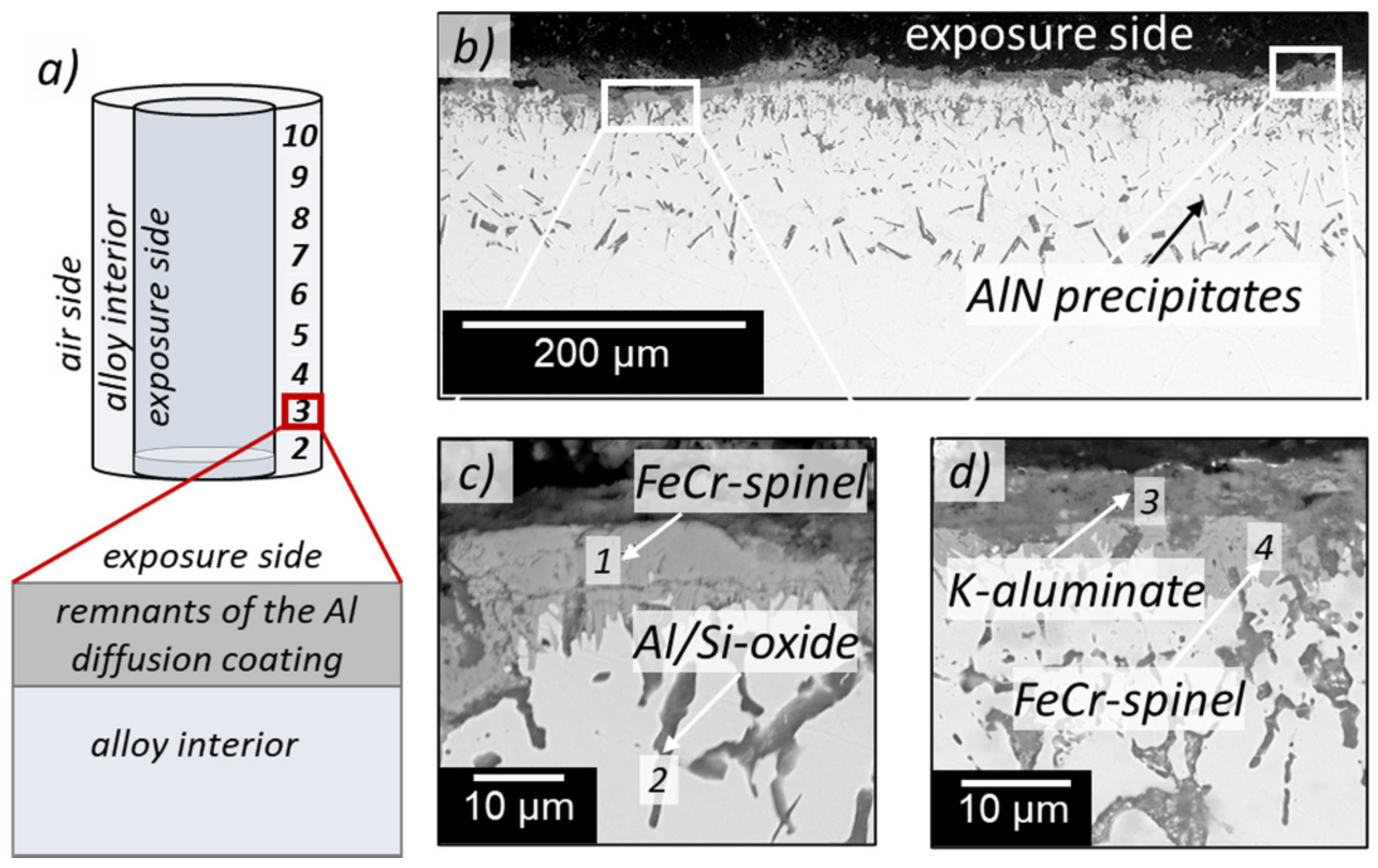
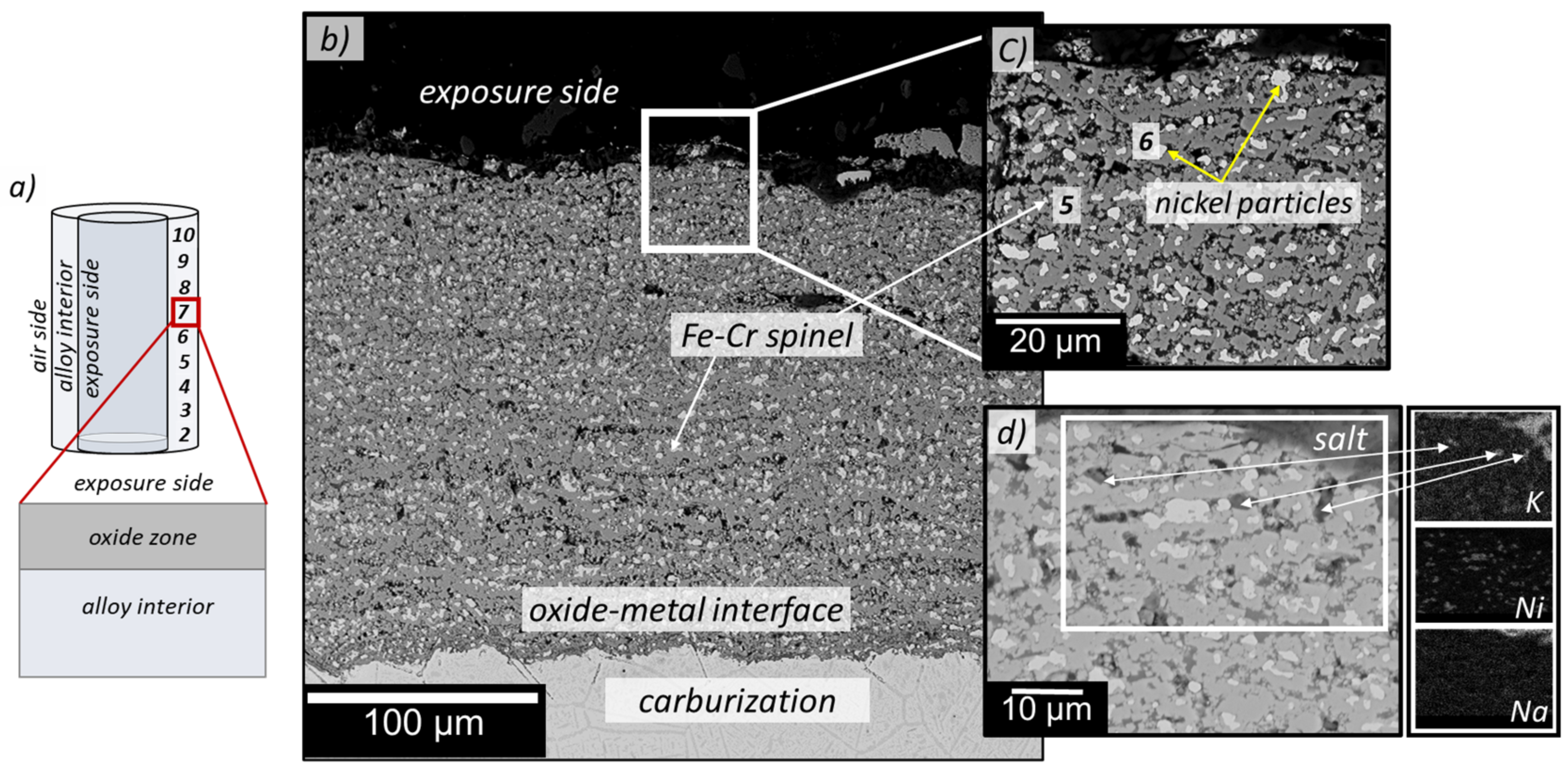
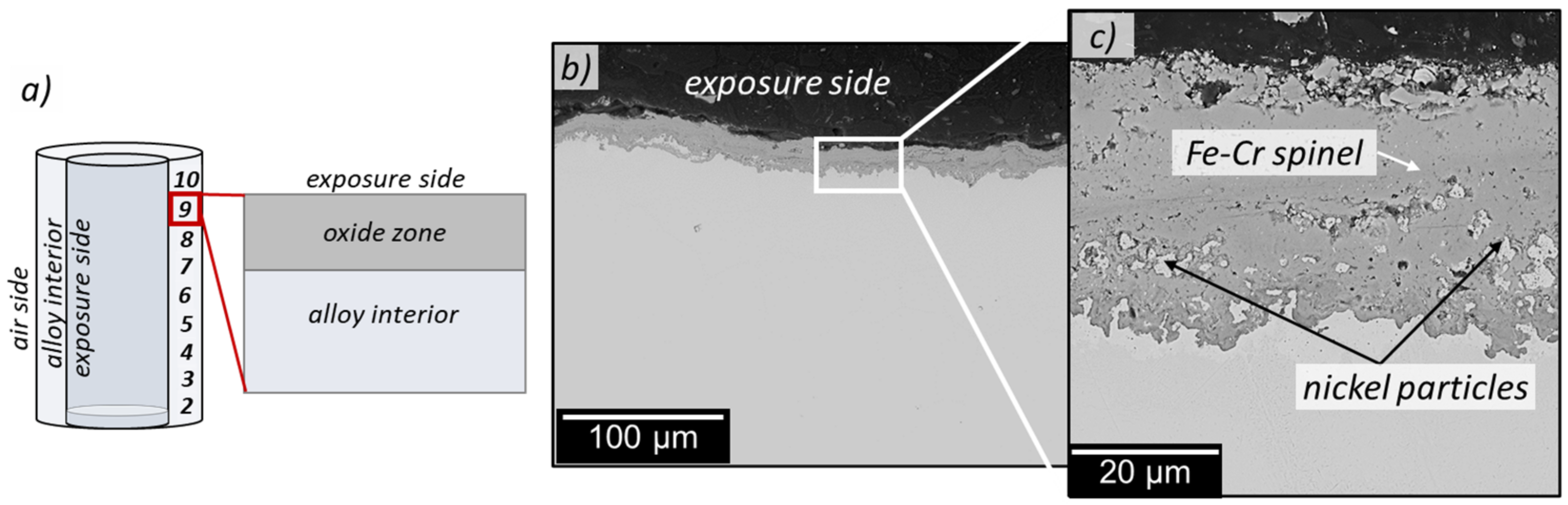
3.3. Cross-Section Analyses

This section describes the selected results of SEM cross-section investigations of the vessel samples. Starting from the vessel’s hottest zone, Figure 4 depicts sample #3, where some aluminum-rich species remain from the coating. Worth noting, the wall thickness was recorded higher at such very few locations where aluminum enrichment was found compared to the majority of the sample surface without remnants from the coating. These aluminum-rich remnants are localized in the oxide scale in the form of potassium aluminate particles; see EDX point analysis shown in Table S1 in the Supplementary Materials. At the same time, Si/Al-oxides are present as internal oxidation products, as are larger aluminum nitrides in depths higher than 100 µm (Figure 4b–d). However, the aluminum remnants in Figure 4 provide no protection since Fe-Cr spinel has already formed beneath the oxide scale. The overall observation regarding the aluminum diffusion coating is that after more than 4000 h operation, it failed on most of the vessel area.
Moving to the vessel’s middle-temperature zone, Figure 5 depicts the oxide layer formed on sample #7 in the absence of any aluminum remnants, a representative for most samples #3 to #8. The oxide scale is highly heterogenous, defect rich, and comprises chromium-rich Fe-Cr spinel and nickel particles. Interestingly, in Figure 5b–d, in agreement with the XRD results, the nickel particles embedded in the porous oxide remained metallic. Sah et al. [29] also reported this finding in their study, where it has been observed that nickel-metal fragments remain in different stainless-steel alloys in contact with a (Li-Na-K)2CO3 melt under flowing CO2/2% O2 mixed gas at 650 °C [29].
In our study, such nickel particles have been observed for all vessel sections. The nickel particles are dispersed all over the oxide scale in the vessel’s middle section, as shown in Figure 5b,c.
Figure 6 presents an overview of the extent of internal precipitation for sample #7, reaching deep into the remaining alloy thickness. Beneath the metal–oxide interface, an internal attack in the form of chromium-rich precipitates along the grain boundaries has been measured, reaching ~800 µm deep into the alloy interior, see chromium element map Figure 6e. Figure 6b–d show intra- and intergranular attack. Chromium carbide precipitates dominate the intergranular attack, while carbides and nitrides comprise the finer intragranular precipitates.
For comparison, the image shown in Figure 6f,g represents the air side of sample #7 facing the lab air environment in between the heating elements and the outer vessel wall. A significantly thinner oxide scale formed, and no environmentally induced precipitation was detected underneath. Few chromium-vanadium precipitates have been observed underneath the oxide–metal interface, which is not unexpected upon annealing at 800 °C, see Table 1.
In the vessel’s colder locations, #9 and #10, the nickel particles are confined in the lower section of the oxide scale (Figure 7b,c), close to the metal–oxide interface, which explains why it was not possible to identify the Ni-FCC pattern in the corresponding XRD spectrum cf. Figure 3.

4. Discussion

Without a doubt, the aluminum powder pack cementation treatment had no lasting impact on the vessel duration. Only a few locations showed remnants of enriched aluminum in the form of an external aluminum-rich oxide scale and precipitates in the alloy, as shown in the results section. Even though the remaining wall thickness is substantially thicker at those spots where higher aluminum values were determined compared to the surrounding corroded sections, there is no reservoir for further protection. The majority of the coating has not survived the chemical attack by alkali species and erosion during the cleaning of the wall. At this point, it is interesting to keep in mind that the experiments performed on coupon samples in this vessel do not experience erosion, unlike the vessel itself. Noteworthy is that sections exhibiting the highest found aluminum fraction in the scale consist of non-protective potassium aluminate. Underneath, chromium-rich iron-chromium spinel is present.
Turning towards the general attack of the alloy in the absence of aluminum diffusion coating remnants, the oxide scale formation is dominated by oxidation by carbon dioxide.
Table 3 has been placed in this discussion section to create intuition about the corrosion processes caused by carbon dioxide. It should be highlighted that the salt species have been omitted for the following calculation since it is carbon dioxide which is ultimately the oxidizing compound. Here, molar fractions of a maximum of five different elements, C, O, Ni, Fe, Cr, are provided for a single point equilibrium calculation at 800 °C utilizing the TCNI 10.0 database in the Thermocalc 2020b software package (Thermo-Calc Software AB: Stockholm, Sweden, 2020) [30]. Keeping the carbon and oxygen molar fraction constant at 8% and 16%, respectively, the residual 76% are stepwise attributed to nickel, nickel/iron, nickel/chromium, and nickel/iron/chromium. In the first scenario, pure nickel, carbon, and oxygen are present exclusively in the gas phase as CO2; no nickel oxides or carbides are stabilized. Moreover, nickel remains metallic in the presence of an equimolar amount of iron and nickel in input II. Metallic nickel dissolves a fraction of iron into the FCC lattice while the remaining iron reacts with part of the CO2 forming wüstite and carbon monoxide. The chromium fraction in input III absorbs the entire carbon and oxygen fraction in the form of corundum and chromium carbides. The equilibrium composition is creating no gas phase. Moreover, in the case of combining all three metals in input IV, with nickel being a major fraction, CO2 and CO are outcompeted by chromium carbide and chromia.
Despite the omission of the alkali carbonate species in the calculation, the corrosion products found in the outer scale emphasize that the predicted metallic nickel particles are in good agreement with XRD and cross-section SEM findings. Iron and chromium are the oxidizing species, while only chromium participates in the formation of carbides, as found in the alloy interior from experiment.
Alkali species are incorporated in the oxide scale confirmed by XRD and cross-section analysis. Interestingly, the major alkali fraction found in the oxide scale is potassium. In previous publications describing the degradation of alloy coupons in the melt-filled alumina crucibles, it has been found that lithium is the foremost reactive alkali species in direct contact with a metal surface [13,14]. However, in this study, the vessel wall was in contact with evaporated salt species from those crucibles, rich in potassium and sodium. This result has consequences on alloy degradation of molten salt storage applications with partial filling, where gas-phase exposed components degrade differently compared to immersed components.
Each alkali species in the oxide undermines the formation of a slow-growing iron-chromium spinel scale as observed for the air side of the vessel. Thus, ongoing oxidation and carburization cause a high alloy consumption of more than 1 mm after only 4000 h.
The residual wall thickness measurements plotted in Figure 2 revealed that the major attack did not occur at the hottest part of the vessel but at an intermediate temperature. This finding is counterintuitive at first, but considering that sample #5 is closest to the gas inlet and samples #7 and #8 are closest to the top edge of the salt-filled alumina crucibles during exposure, the concentration of evaporated salt species can be considered the highest at these sections. Therefore, one can conclude that high temperature and a high alkali species concentration create a higher corrosive environment.
The gas flow is directed upwards towards the outlet in the lid. Subsequently, the major fraction of evaporated salt species is also expected to interact with the wall sections #5 to #10, eventually condensing at the colder lid. The vessel lower sections, samples #2 and #3, did not lose as much of their wall thickness even though the temperature has been highest. Carbon dioxide and high temperature alone do not cause high deterioration rates measured. In conjunction with higher concentrations of alkali species in the gas stream (#5 to #8), heterogeneous oxide scale rich in particulate corrosion products, cracks, and pores were observed.
In conjunction with this heterogeneous oxide scale, the alloy exhibited a rich precipitation behavior dominated by chromium-rich precipitates. These are mainly environmentally induced chromium carbide precipitates. They are reaching deep into the alloy, more than 800 µm.
Considering that a large fraction of the material has already been consumed, the loss of the original alloy properties reaches cumulatively nearly 2 mm after 4000 h operation for sample #5, showing the strongest corrosion attack.
On the air side, underneath the dense and adhesive iron-chromium spinel, only a few traces of Cr-V-rich precipitates have formed, agreeing with the single point equilibrium phases listed in Table 1 for 800 °C annealing of the 253MA alloy.

5. Summary

The following observations have been made and can be taken into consideration for future experimental setups but also for thermal storage modules in which not every module is in direct contact with the eutectic alkali carbonate melt:
-
More than 4000 h of intermittent operation at high temperature in an alkali carbonate-containing CO2 gas environment significantly damaged a furnace vessel made of alloy 253MA.
-
An additional aluminum diffusion coating applied to the 253MA vessel surface before operation, had no lasting effect on the material degradation processes.
-
The severity of the corrosion attack does not follow the temperature gradient across the vessel but rather the source of evaporating salt into the gas stream and its flowing direction.
-
The amount of potassium from the evaporating salt species into corrosion products is significantly higher than observed for immersion samples in direct contact with the melt, where lithium was dominating instead.

Supplementary Materials

The following supporting information can be downloaded at: https://www.mdpi.com/article/10.3390/en15093241/s1. Table S1: EDX point analysis in Figure 4, Figure 5, Figure 6 and Figure 7 measured in at% only cations normalized to 100%, counterions are added without quantification.

Author Contributions

Data curation, E.H., A.W. and C.G.; Supervision, C.G.; Writing—original draft, E.H.; Writing—review & editing, C.G. All authors have read and agreed to the published version of the manuscript.

Funding

This research and APC were funded by HTC, the High Temperature Competence Center of Sweden, grant number 22581-5, and the Swedish Energy Agency, SOLEL 44653-1.

Institutional Review Board Statement

Not applicable.

Informed Consent Statement

Not applicable.

Data Availability Statement

Not applicable.

Acknowledgments

We thank the head of the Chalmers mechanical workshop, Esa Väänänen, for manufacturing and decommissioning the 253MA vessels and his observations during cutting through the alloy. Financial support was provided by HTC, the High Temperature Competence Center of Sweden, during the contract period 2017–2021, supported by the Swedish Energy Agency.

Conflicts of Interest

The authors declare no conflict of interest.

References

  1. Mehos, M.; Turchi, C.; Vidal, J.; Wagner, M.; Ma, Z.; Ho, C.; Kolb, W.; Andraka, C.; Kruizenga, A. Concentrating Solar Power Gen3 Demonstration Roadmap; NREL/TP-5500-67464 United States 10.2172/1338899 NREL English; National Renewable Energy Lab. (NREL): Golden, CO, USA, 2017. Available online: https://www.osti.gov/servlets/purl/1338899 (accessed on 15 August 2021).
  2. Zhao, Y.; Li, P.; Jin, H. Heat Transfer Performance Comparisons of Supercritical Carbon Dioxide and NaCl–KCl–ZnCl2 Eutectic Salts for Solar s-CO2 Brayton Cycle. Energy Procedia 2017, 142, 680–687. [Google Scholar] [CrossRef]
  3. Yin, J.-M.; Zheng, Q.Y.; Peng, Z.R.; Zhang, X.R. Review of supercritical CO2 power cycles integrated with CSP. Int. J. Energy Res. 2019, 44, 1337–1369. [Google Scholar] [CrossRef]
  4. Ho, C.K.; Carlson, M.; Garg, P.; Kumar, P. Technoeconomic Analysis of Alternative Solarized s-CO2 Brayton Cycle Configurations. J. Sol. Energy Eng. 2016, 138, 051008. [Google Scholar] [CrossRef]
  5. Walczak, M.; Pineda, F.; Fernández, Á.G.; Mata-Torres, C.; Escobar, R.A. Materials corrosion for thermal energy storage systems in concentrated solar power plants. Renew. Sustain. Energy Rev. 2018, 86, 22–44. [Google Scholar] [CrossRef]
  6. Patel, N.S.; Pavlík, V.; Boča, M. High-Temperature Corrosion Behavior of Superalloys in Molten Salts—A Review. Crit. Rev. Solid State Mater. Sci. 2017, 42, 83–97. [Google Scholar] [CrossRef]
  7. Kuravi, S.; Trahan, J.; Goswami, D.Y.; Rahman, M.M.; Stefanakos, E.K. Thermal energy storage technologies and systems for concentrating solar power plants. Prog. Energy Combust. Sci. 2013, 39, 285–319. [Google Scholar]
  8. Frangini, S. Corrosion of structural materials in molten carbonate fuel cells: An overview. Molten Salt Forum 2003, 7, 135–154. [Google Scholar]
  9. Frangini, S. Corrosion Behavior of AISI 316L Stainless Steel and ODS FeAl Aluminide in Eutectic Li2CO3–K2CO3 Molten Carbonates under Flowing CO2–O2 Gas Mixtures. Oxid. Met. 2000, 53, 139–156. [Google Scholar] [CrossRef]
  10. Lee, K.S.; Cho, K.; Lim, T.H.; Hong, S.-A.; Kim, H. Corrosion behaviour of sensitized AISI-type 316L stainless steel in molten carbonate fuel cell in cathode-gas environment. J. Power Sources 1999, 83, 32–40. [Google Scholar] [CrossRef]
  11. Sarvghad, M.; Will, G.; Steinberg, T.A. Corrosion of Inconel 601 in molten salts for thermal energy storage. Sol. Energy Mater. Sol. Cells 2017, 172, 220–229. [Google Scholar] [CrossRef]
  12. Hamdy, E.; Nockert-Olovsjö, J.; Geers, C. Additional data and experimental setups used for the study on alloys in contact to high temperature eutectic melts for thermal storage. Data Brief 2021, 38, 107446. [Google Scholar] [CrossRef]
  13. Hamdy, E.; Nockert-Olovsjö, J.; Geers, C. Perspectives on selected alloys in contact with eutectic melts for thermal storage: Nitrates, carbonates and chlorides. Sol. Energy 2021, 224, 1210–1221. [Google Scholar] [CrossRef]
  14. Hamdy, E.; Strach, M.; Nockert-Olovsjö, J.; Geers, C. Differentiation in corrosion performance of alumina forming alloys in alkali carbonate melts. Corros. Sci. 2021, 192, 109857. [Google Scholar] [CrossRef]
  15. TNguyen, D.; Zhang, J.; Young, D.J. Effects of cerium and manganese on corrosion of Fe–Cr and Fe–Cr–Ni alloys in Ar–20CO2 and Ar–20CO2–20H2O gases at 650 °C. Corros. Sci. 2015, 100, 448–465. [Google Scholar] [CrossRef]
  16. Johansson, C.; Lind, M. Evaluation of the η (Eta) Nitride with Three Laboratory Melts. Master’s Thesis, Royal Institute of Technology, Stockholm, Sweden, 2015. [Google Scholar]
  17. Sandström, R.; Farooq, M.; Lundberg, M. Precipitation during long time ageing in the austenitic stainless steel 310. Mater. High Temp. 2014, 29, 8–16. [Google Scholar] [CrossRef]
  18. TCFE, version 10.1; Thermo-Calc Software AB: Stockholm, Sweden, 2020.
  19. Xi, X.; Kong, C.; Zhang, J. Effect of Cyclic Reaction on Corrosion Behavior of Chromium-Containing Alloys in CO2 Gas at 650 °C. Oxid. Met. 2020, 93, 131–157. [Google Scholar] [CrossRef]
  20. Oskay, C.; Meißner, T.M.; Dobler, C.; Grégoire, B.; Galetz, M.C. Scale Formation and Degradation of Diffusion Coatings Deposited on 9% Cr Steel in Molten Solar Salt. Coatings 2019, 9, 687. [Google Scholar] [CrossRef] [Green Version]
  21. Wu, Y.-T.; Ren, N.; Wang, T.; Ma, C.-F. Experimental study on optimized composition of mixed carbonate salt for sensible heat storage in solar thermal power plant. Sol. Energy 2011, 85, 1957–1966. [Google Scholar] [CrossRef]
  22. Vignarooban, K.; Xu, X.; Arvay, A.; Hsu, K.; Kannan, A.M. Heat transfer fluids for concentrating solar power systems—A review. Appl. Energy 2015, 146, 383–396. [Google Scholar] [CrossRef]
  23. Simmons, L.; Lowden, L.F.; Ehlert, T.C. A mass spectrometric study of potassium carbonate and potassium oxide. J. Phys. Chem. 1977, 81, 706–709. [Google Scholar] [CrossRef]
  24. Tetsuo, K. Measurements of the Vapor and Dissociation Pressures of Potassium Sulfate and Carbonate at High Temperatures. Bull. Chem. Soc. Jpn. 1972, 45, 15–19. [Google Scholar] [CrossRef] [Green Version]
  25. Motzfeldt, K. The Thermal Decomposition.of Sodium Carbonate by the Effusion Method. J. Phys. Chem. 1955, 59, 139–147. [Google Scholar] [CrossRef]
  26. Sergeev, D.; Yazhenskikh, E.; Kobertz, D.; Müller, M. Vaporization behavior of Na2CO3 and K2CO3. Calphad 2019, 65, 42–49. [Google Scholar] [CrossRef]
  27. Maru, H.C. Alkali Metal Carbonates. In Molten Salt Techniques; Lovering, D.G., Gale, R.J., Eds.; Plenum Press: New York, NY, USA; Plenum Publishing Corp.: New York, NY, USA, 1983; Volume 1, p. 272. [Google Scholar]
  28. Atkins, P.W. Chemical Principles: The Quest for Insight; W.H. Freeman: New York, NY, USA, 2000. (In English) [Google Scholar]
  29. Sah, S.P.; Tada, E.; Nishikata, A. Corrosion behaviour of austenitic stainless steels in carbonate melt at 923 K under controlled CO2-O2 environment. Corros. Sci. 2018, 133, 310–317. [Google Scholar] [CrossRef]
  30. TCNI, version 10.0; Thermo-Calc Software AB: Stockholm, Sweden, 2020.
Figure 1. (a) Schematic illustration of the furnace setup showing the design for two vessels, gas supply, and crucible position for immersion tests in molten salt. (b) Image of the decommissioned vessel with sample sections drawn outside. (c) Temperature profile within the vessel during operation at 800 °C.
Energies 15 03241 g001
Figure 2. Average residual metal wall thickness was measured for samples taken at different heights in the vessel. The location of the gas inlet and the upper edge of the salt-filled alumina crucibles are highlighted (see schematic in Figure 1a).
Energies 15 03241 g002
Figure 3. Selected XRD patterns of vessel samples #3, #7, and #9 after 4000 h exposure to evaporated alkali carbonates at different temperatures depending on the sample position, see Figure 1c.
Energies 15 03241 g003
Figure 4. (a) Schematic illustration of the vessel highlights the main corrosion regimes in the hottest section after 4000 h exposure to evaporated alkali carbonate species. (b) Cross-section SEM image of sample #3 showing remnants of the aluminum diffusion coating. High magnification of image (b) presenting (c) Fe-Cr spinel covers the surface and formation of Al/Si oxide droplets distributed beneath the oxide scale. (d) Potassium aluminate scale remnant above the Fe-Cr spinel.
Energies 15 03241 g004
Figure 5. (a) Schematic illustration of the vessel highlights the main corrosion regimes in the middle-temperature section after 4000 h exposure to evaporated alkali carbonate species. (b) Low-magnification BSE image of sample #3 showing oxide layer and carburization beneath oxide-metal interface. (c) High-magnification of image (b) presenting the oxide scale on sample #7 comprising Fe-Cr spinel and nickel particles. (d) K, Ni, and Na EDS element maps showing potassium species incorporated in the oxide zone.
Energies 15 03241 g005
Figure 6. (a) Sketch for the sample position in the vessel and cross-section partitioning, (b) cross-section BSE images of sample #7 from the exposure side ((be) images). (c) Environmentally induced intra- and intergranular precipitation, (d) EDS chromium element map in one grain isolated, (e) EDS chromium element map starting from the metal–oxide interface showing deep carburization induced precipitation on the exposure side of the vessel. (f,g) BSE images from the air side of the vessel. The Fe-Cr spinel oxide is only 2 µm thick on average.
Energies 15 03241 g006
Figure 7. (a) schematic illustration of the tested vessel highlights the main corrosion regimes in the coldest section of the vessel after 4000 h exposure to evaporated alkali carbonate species. (b) Oxide scale on sample #9. (c) High-magnification of image b showing nickel as small fragments through the Fe-Cr spinel.
Energies 15 03241 g007
Table 1. Measurement of alloy 253MA in wt% and a corresponding backscatter electron image of the microstructure before exposure. In the lower part of the table: Calculated phase compositions of alloy 253MA at 1050 °C and 800 °C at equilibrium.
Measured Composition of Alloy 253MA (wt%)
FeCSiMnPSCrNiNOthers
Bal.~0.08≤1.97≤0.55≤0.02≤0.16~20.9~10.6≤0.14Ce; V
Energies 15 03241 i001Microstructure of 253MA alloy before exposure; only Ce-containing precipitates are observed.
TCFE single point calculation considering the nominal alloy composition and for Mn: 0.55%; P: 0.002%; S: 0.0016%
253MA at 1050 °C253MA at 800 °C
PhaseMass fraction [%]PhaseMass fraction [%]
FCC99.29FCC92.14
(Cr,V)2N0.61(Cr,V)2N0.18
M23C60.04M23C61.31
(Mn,Cr)S0.02(Cr,Fe)3P0.01
Ce2S30.04Ce2S30.04
η-phase2.65
(Cr,Mn)S0.02
σ-phase3.65
Table 2. Lifecycle of the investigated vessel and the operation conditions.
Operation ConditionsDurationReheating Cycle
(Every 336 h)
Duration of the Vessel Opening
(Pouring the Melt Off, Air, 500 °C)
Process
Aluminum-diffusion coating
Step I (at 500 °C), Ar1 h--
Step II (at 900 °C), Ar3 h--
Pre-oxidation step (at 900 °C), air24 h--
Exposures to alkali carbonate melts (CO2, 800 °C)
Experiment no. 172 h-75 min
Experiment no. 2500 hOnce75 min
Experiment no. 3500 hOnce60 min
Experiment no. 4168 h-45 min
Experiment no. 51000 hThrice45 min
Experiment no. 672 h-50 min
Experiment no. 71000 hThrice45 min
Experiment no. 8168 h-60 min
Experiment no. 972 h-60 min
Experiment no. 1072 h-55 min
Experiment no. 11500 hOnce60 min
Table 3. Single point equilibrium calculation for C = 8 mol%, O = 16 mol% and Ni + Fe + Cr = 76 mol% in four input sets, T = 800 °C, p = 1 bar and the corresponding output phases at equilibrium calculated by using the Thermocalc 2020b software package, TCNI 10.0 database in the (Thermo-Calc Software AB: Stockholm, Sweden, 2020) [30]).
ElementInput I [mol%]PhasesInput II [mol%]PhasesInput III [mol%]PhasesInput IV [mol%]Phases
C0.08Ni FCC; CO20.08CO2/CO (55/45);
Ni-Fe FCC; FeO
0.08Corundum Cr2O3;
Ni-Cr FCC; M7C3
0.08Corundum Cr2O3;
Ni-Fe FCC; M3C2; Graphite
O0.160.160.160.16
Ni0.760.380.380.38
Fe 0.38 0.19
Cr 0.380.19
Publisher’s Note: MDPI stays neutral with regard to jurisdictional claims in published maps and institutional affiliations.

