Review

Current Electromagnetic Compatibility Problems of High-Power Industrial Electric Drives with Active Front-End Rectifiers Connected to a 6–35 kV Power Grid: A Comprehensive Overview

Research and Development Department, Nosov Magnitogorsk State Technical University, 455000 Magnitogorsk, Russia
*
Author to whom correspondence should be addressed.
Energies 2023, 16(1), 293; https://doi.org/10.3390/en16010293
Submission received: 13 November 2022 / Revised: 11 December 2022 / Accepted: 22 December 2022 / Published: 27 December 2022

Abstract

:
Today, electric drive systems based on frequency converters with active front-end rectifiers (FC-AFEs) are widespread across industries. In the course of the upgrade of production facilities, such systems replace the conventional converters with thyristor- and diode-based rectifiers. FC-AFEs have the following advantages: the capacity to regenerate the power to the grid and the capacity to operate at the set power factor. The manufacturers of FC-AFEs also claim that their products have the best electromagnetic compatibility (EMC) with the power grid. The best EMC shall be achieved via a multilevel FC-AFE topology and specialized pulse-width modulation (PWM) algorithms for AFE rectifiers. However, the experience of operating mid-voltage high-power electric drives with an FC-AFE in 6–35 kV factory distribution grids with non-linear frequency response due to resonant phenomena refutes the claims of the FC-AFE manufacturers. Resonant phenomena in 6–35 kV grids are caused by the interaction of the inductance of grid components (transformers, reactors) and the capacitance of output cable lines. If the resonance frequency at a sufficient amplitude corresponds to the harmonic frequency of the current consumed by the FC-AFE, the distribution grid will feature high-frequency voltage distortions. This may lead to failures in voltage quality-sensitive electrical consumers. This problem recurred at various metallurgical companies. The purpose of this research is to make a comprehensive overview of the EMC problems during the operation of FC-AFEs at active production facilities, as well as the analysis of the technical solutions aimed at the improvement of the EMC of high-power FC-AFEs with the power grid.

1. Introduction

Modern high-power electric drives used in industrial machinery, such as the electric drives of metal plant rolling mills, that were introduced over the last decade are mainly based on medium-voltage multilevel FC-AFEs and asynchronous (synchronous) motors [1,2,3]. This type of power converter has a number of advantages over the previous-generation frequency converter with diode- or thyristor-based rectifier modules: (1) the capacity to regenerate the power to the grid under the generating modes of the electric drive; (2) the capacity to adjust the power coefficient at the FC-AFE input; (3) the improved harmonic spectrum of the power consumed from the grid due to the use of specialized active rectifier pulse-width modulation algorithms. The listed advantages resulted in the mass introduction of high-power electric drives based on FC-AFEs at industrial facilities. However, the experience of operating these power converter shows that FC-AFEs have some drawbacks, the most significant of which is the high probability of dramatic voltage quality drop in the factory 6–35 kV grid due to the overlapping of high-voltage harmonics of the input voltage and current and the resonant regions of power grid frequency response.
Previous research has shown that numerous metal plants in Russia and other countries face serious problems with the operational reliability of FC-AFE-based automated electric drive systems, as well as problems assuring the electromagnetic compatibility of FC-AFEs with the 6–35 kV factory grid. For instance, some of the Russian companies, e.g., Balakovo Steel Factory (Balakovo, Saratov Oblast), Abinsk Electric Steel Works (Abinsk, Krasnodar Krai), Severstal Cherepovets Steel Mill (Cherepovets, Vologda Oblast), etc., faced problems with the operation of electrical equipment due to high voltage distortion in the 10 kV grid, as well as the failures of frequency converters operating parallel to powerful sources of high-order harmonics, namely FC-AFEs integrated into the main electric drives of rolling mills. The deterioration of voltage quality in these cases was caused by the presence of resonant phenomena in the frequency response of the grid that amplified the higher voltage harmonics when the resonance regions corresponded to the frequencies of the generated higher harmonics of the FC-AFE current.
The problem of the quality deterioration of the harmonic spectrum of the voltage in the 6–35 kV factory grid when high-power FC-AFEs are used is that in certain power grid configurations with long cable lines, the equivalent capacitance of 6–35 kV cables that interacts with the inductances of the 110–220 kV/6–35 kV grid transformers of the main step-down substation (MSDS) and line reactor inductances in MSDS cells (if any) induces current resonances in the grid frequency response that significantly increase the grid impedance in the specific frequency range. The higher harmonics of the mid- and high-level frequency range current, consumed by FC-AFEs, may enter these resonance regions, which results in the amplification of higher voltage harmonics with the same numbers in the sections of the 6–35 kV MSDS that are the point of common coupling for the factory consumers. Note that the establishment of the “dirty” and “clean” sections in the 6–35 kV switchgear of the main step-down substation of the factory with the high-power non-linear loads energized specifically from the “dirty” section is not always possible due to the limitations of the configuration of the existing medium-voltage switchgear of the MSDS. Thus, it is necessary to use some technical solutions to assure the electromagnetic compatibility of FC-AFEs and the 6–35 kV power grid. The analysis of the research and engineering literature, as well as the results of research carried out by our team, show that the leading manufacturers of FC-AFEs, in most cases, cannot properly implement the technical solutions to assure the electromagnetic compatibility of FC-AFE-based high-power electric drives and the medium-voltage factory grid. The use of specialized PWM algorithms with selective harmonic elimination or mitigation (Selective Harmonic Elimination PWM [4,5,6,7,8,9,10,11,12,13,14,15,16,17,18,19,20,21,22,23,24,25,26,27,28,29,30,31,32,33,34] and Selective Harmonic Mitigation PWM algorithms [35,36,37,38,39,40,41,42,43]) or other (Space Vector PWM [44,45]) may not always provide the effect required to assure the set voltage quality in common MSDS sections due to the lack of the adaptation function to the resonant phenomena in the 6–35 kV power grid for these algorithms. Note that the input grid filters in FC-AFEs, as well as the conventional narrow-band higher harmonic filter, installed in the high-power FC-AFE-based electric drives, cannot assure the complete elimination of negative impacts of FC-AFEs on the power quality due to the complexity of resonant phenomena [46], which is manifested in the presence of several resonance maximums in various regions of the frequency response.
In addition, note that converter manufacturers often provide the harmonic spectrum data for the FC-AFE currents and voltages only up to harmonics 40–50 for promotion purposes. This can be explained by the limits set by the regulatory standards [47]. On the other side, FC-AFEs generate higher-order harmonics than those set out in standards regulating the power quality. The manufacturers’ failure to provide information on the exact harmonic spectrum of FC-AFE currents and voltages prevents us from developing the required technical solutions to assure the EMC at the design stage of the FC-AFE electric drives. This, in turn, results in the problems described above.
The purpose of this research is to provide a comprehensive overview of electromagnetic compatibility problems of high-power FC-AFE-based electric drives and the 6–35 kV factory distribution grids. This research reviews the existing methods of assuring the EMC, as well as their prospects and drawbacks. In addition, this research presents the authors’ technical solutions that assure the EMC of high-power industrial FC-AFEs and the 6–35 kV power grid by using the adaptive PWM algorithms for AFE rectifiers and specialized passive filters for the correction of the grid frequency response.

2. The Features of the Electric Power Equipment and the Power Systems of FC-AFEs within High-Power Industrial Electric Drives

Today, high-power industrial electric drives, e.g., main electric drives of rolling mills, are designed based on three-level frequency converters with AFE, VSI, and synchronous (asynchronous) electric motors [1,2,3].
The power circuit of AFE and VSI is based on fully-controlled semiconductor modules (IGCT thyristors or IGBT transistors). The structure of AFE is completely identical to VSI. Each of the converter legs comprises four controlled IGCT thyristors (Figure 1) with connected in parallel and clamped diodes. The clamped diodes connect six medium power modules to the converter zero point. The diodes are connected to the DC link represented as two equivalent series-connected capacities. The voltage on one capacitor is half the DC link voltage. The point between the capacitors forms the zero potential of the converter [48,49,50,51].
We review the operating principle of the three-level AFE based on phase A of the FC-AFE shown in Figure 1. The AFE input voltage is formed as a set of positive and negative rectangular impulses. Only two out of the four T1, T2, T3, T4 modules can be «closed» at the same time; it connects the potentials UDC/2, 0 and −UDC/2 to the AFE phase A input. For example, thyristors T2 and T3 are switched on to produce 0 on the input. Depending on the input inverter current II direction, the D5 diode and T2 thyristor or the D6 diode and T3 thyristor will be operated. At another moment, thyristors T1 and T2 are open, and the input voltage is –UDC/2. If thyristors T3 and T4 are open, the input voltage is +UDC/2. Diodes D1, D2, D3, and D4, as on uncontrolled rectifiers, will be opened at the positive anode-to-cathode voltage. All other switchings are carried out the same way. Thus, of the four modules in every leg, only the two that connect the DC link to the load at three points (P, 0, and N) can be switched on at the same time. These connections form three possible states for each of the legs: the P connection to the positive point of the DC link, the O connection to the neutral point of the DC link, and the N connection to the negative point of the DC link. Considering all the possible states relative to the 3 phases of the 3-level converter, we get 27 combinations [52,53]. The combinations are shown in Table 1.
The AFE inverts the constant filtering capacitor voltage to the pulse voltage at its AC terminals. These terminals are connected to the grid via reactor L (Figure 1). Unlike the regulated operating voltage frequency on the AC terminals of VSI, the operating voltage frequency on the AC terminals of AFE is constant and equal to the grid frequency. The difference between the instance values of the sinusoidal voltage of the grid and the pulse voltage on the AC terminals of the AFE is received by reactor L. Due to the use of the PWM, the pulse voltage generated by the AFE on the AC side has a favorable harmonic spectrum, where the main harmonic and the higher harmonics vary significantly by frequency. This provides favorable conditions for the filtering of the higher harmonics of the grid current consumed by reactor L. The AFE converts the AC consumed from the grid, which is close to sinusoidal, to the pulse output current with variable and constant components. The variable component is closed via the capacitors that limit the voltage pulsation in the DC link from the variable component of the AFE output current. The capacitors perform the same function for the variable component of the current consumed by the VSI. The constant component of the AFE output current feeds the capacitors and compensates for the consumption of the DC supplied to the input circuit by the VSI [54,55,56].
The phase angle of the consumed current depends on the ratio of amplitudes and phase angles of voltages applied to reactors from the grid side and the AFE side, as well as the reactor parameters. Using the AFE control system to adjust the main harmonic parameters of its AC voltage on the AC terminals, we can assure the required current spectrum with the grid phase angle. In other words, it is possible to assure the converter’s operation with the power factor value. Therefore, the AFE frequency converter can be used in the grid as a neutral element, as a source, or as a reactive power consumer.
To connect the FC-AFE to the grid, we can use various connection diagrams [57]. Medium-power drives normally use 6-pulse rectification circuits (Figure 2). These are the simplest ones, comprising one FC-AFE and a single-winding power transformer whose windings are connected using a star/star design, and the phase shift angle between the primary and secondary voltage is at 0. The FC-AFE connected to the 6-pulse circuit generates harmonics divisible by 6n ± 1, where n is a positive integer to the grid.
The electric drives of high-power rolling mills use multi-pulse rectification circuits, usually 12-pulse ones. To accomplish this, two FC-AFEs with a common DC link are connected in parallel. The connections to the frequency converter grid are implemented via matching power transformers.
To make a 12-pulse rectification circuit, two matching transformer use options are stipulated (Figure 3). Two power transformers are used with series-connected primary windings. The secondary windings of one transformer are connected using the star design, and the second transformer uses the triangle design. This transformer winding connection helps achieve a 30-degree shift angle in the secondary voltage. Due to this, there are no harmonics divisible by six in the total voltage on the primary side of the transformer. The lack of harmonics divisible by six in the total voltage on the primary side of the transformer can be explained using the seventh harmonic as an example. The voltage on the secondary side of the transformers has a 30-degree shift angle by reference to the main harmonic. For the seventh harmonic, this angle is seven times greater, and it equals 210 degrees. The phase B main harmonic voltage relative to phase A has a shift angle of 120 degrees, and relative to the seventh harmonic the shift angle is 2·360° + 120° = 120°. The voltage on the primary side of transformer T1 is determined as a difference of secondary phase voltages taking into account the transformation coefficient. The voltage of the seventh harmonic on the primary side of transformers T1 and T2 is opposite in phase, and therefore they mutually compensate one another. These statements are true for other harmonics divisible by six.
Another option for the development of a 12-pulse rectification circuit is the use of one three-winding transformer with the primary winding connected using the triangle design, one of the secondary windings connected using the star, and another secondary winding connected using the delta. This way, the shift angle between the primary and secondary voltage is 300. However, the usage of one three-winding transformer with one magnetic system stipulates additional losses in the magnetically conductive steel due to the mixing of various harmonic components [58].
Another popular FC-AFE power grid connection option is the use of an 18-pulse circuit (Figure 4). For this option, three power transformers are used with primary windings connected in series. The secondary windings of two of the transformers are connected using the zigzag. To do this, the secondary windings are divided into sections equal to 35, and 35% of the primary windings are needed to make the required shift angle between the primary and secondary voltages (±20°). The secondary winding of the third transformer is connected using the star. Due to this connection of the secondary windings, we can achieve a shift angle between the primary and secondary voltages of 0° and ±20°. The 18-pulse circuit option has better-consumed current quality than 6- and 12-pulse circuits. This is because, during the use of the 18-pulse circuit, the FC-AFE consumed current and voltage feature harmonics 18n ± 1 [59].

3. Constructing Frequency Converter Control Systems with AFE Rectifiers: The Analysis of the Existing PWM Algorithms for AFE Rectifiers

To control the AFE power switches, we use a vector control system oriented relative to the grid voltage vector. The AFE control system shall maintain the DC link voltage at the reference value and make sure that the power factor at the converter input equals to one. According to this representation of the control object, the control system is made as a two-circuit one with an internal two-channel adjustment system for consumed grid currents and an external single-channel system for the automated adjustment of the AFE rectified voltage [60,61].
The internal control circuit dq of the component currents is a combined system of automated adjustment that uses the adjustment principles of variance and disturbance. It receives signals from the power circuits, where the fixed coordinate system abc is converted to the rotating system dqo. After that, the actual values of converted currents, id and iq, are compared with the set currents, idref and iqref, whose values are generated in the external automated adjustment system that is subject to the external regulation system for the rectified voltage. The misalignment signals are processed by the proportion-integral current regulators (PIId and PIIq) and, after the complementation with the compensating links, they are sent to the control voltage vector, Ud and Uq, in the direct channel of the control system. The reverse conversion of coordinates generates control actions Uabcref, which are sent to the PWM module where, depending on the PWM algorithm used, AFE control impulses are generated.
The systems of differential equations for the fixed system of coordinates abc (1) and the rotating system dqo (2) are shown below.
{ U g r i d . a = i a R + p L i a + U A F E a ; U g r i d . b = i b R + p L i b + U A F E b ; U g r i d . c = i c R + p L i c + U A F E c .
where Ugrid.a, Ugrid.b, and Ugrid.c are the instant phase voltage values of the grid; UAFEa, UAFEb, and UAFEc are the instant values of AFE phase voltages; ia, ib, and ic are the instant values of the AFE phase currents; R and L are the active resistance and inductance of the reactor.
{ U g r i d . d = U A F E d + i d R + p L i d + ω L i q ; U g r i d . q = U A F E q + R i q + p L i q ω L i d .
where Ugrid.d and Ugrid.q are the grid voltages; UAFEd and UAFEq are the AFE input voltages; id and iq are the current values on axes d and q.
The simplified structural diagram of the PWM algorithm with fixed switching angle values is shown in Figure 5. The operating principle of the algorithm is as follows: the setting current is generated in the external voltage adjustment circuit in the DC link using the active component idref, following the comparison of the actual UDC and UDCref voltage values in the DC link. The voltage adjustment error is eliminated with the proportion-integral regulator PIDC. Then, the generated value of the active current component idref is compared to the actual current value id. The current adjustment error is processed by the proportional-integral current regulator PIId that produces the required shift angle θshift for the AFE voltage phase. The calculated angle θshift is added to the reference signal wt that is generated in the phase locked loop module (PLL). The reference signal sheared by the angle θ is sent to the impulse generation module where it is compared to the previously- calculated switching angles. If the reference signal θref and the switching angles are equal, the AFE control impulses are generated [62].
To control the AFE modules, modified PWM algorithms with low switching frequency are used. Fixed Pulse Pattern Control is one of these PWM algorithms. The PWM method with fixed switching angle values differs from the conventional algorithms because it calculates the switching angles beforehand rather than in real time as in the conventional algorithms (Figure 6). The criterion that is used for the calculation of the switching angles is the minimum active loss value in power switches and the limit of the higher voltage harmonics generated in the grid (the minimum total current distortion coefficient (THD)). The operating principle of the PWM algorithm used stipulates the fixation of the voltage amplitude and the adjustment of the voltage phase at the AFE input relative to the grid voltage phase. In other words, the adjustment of the active current component occurs through the changing of the reactive component. For the algorithm, αi is the switching angle for the first and third ¼ period of AFE voltage and βi is the switching angle for the second and forth ¼ period.
The AFE input voltage is formed as rectangular impulses with an odd harmonic range, whose amplitudes depend on the quality of impulses over a quarter-period and the switching angle values. The switching angles are selected so that the voltage curve does not have the most significant harmonics. The main harmonic remains at the level set by the modulation index. The correlations between the switching angles are determined by the system of Equation (1) [63].
To solve the system of Equation (3), we used the direct search of initial approximations. The produced solutions to the system of equations shall satisfy Condition (4).
F ( α ) = { m i = 1 N ( 1 ) i + 1 c o s ( α i ) ; 0 i = 1 N ( 1 ) i + 1 c o s ( n 1 α i ) ; 0 i = 1 N ( 1 ) i + 1 c o s ( n 2 α i ) ; 0 i = 1 N ( 1 ) i + 1 c o s ( n N α i ) ;
The dependency of the switching angles and the modulation coefficient is shown in Figure 7.
0 < α 1 < α 2 < < α N < π / 2
The AFE control system forms the modulation index m and angle θ . The modulation index is sent to the module with the pre-calculated switching angles, and the module produces the switching angles to be compared to the sawtooth carrying signal. The comparison is performed using logical Expressions (5)–(7). Logical expressions are a condition for the formation of control system 1 at the output. If none of the conditions are fulfilled, the output is set to 0. Expressions (5)–(7) are true for the positive semi-wave, for the negative semi-wave of the voltage curve, they should be symmetrically reflected relative to the wt axis. The structural diagram of the PWM algorithm with selective harmonic elimination is shown in Figure 8.
( m > α 1 ) & ( m < α 2 )
( m > α 3 ) & ( m < 180 α 3 )
( m > 180 α 2 ) & ( m < 180 α 1 )
The drawback of the SHEPWM algorithm described above is that the uncompensated harmonics are not accounted for in the calculations of the switching angles, and they can reach very large amplitudes. Selective Harmonic Mitigation (SHMPWM) is a more efficient [64,65,66,67] PWM algorithm that reduces the zeroing condition of the harmonics to the set value. The goal of the algorithm is not to eliminate some of the harmonics, as in SHEPWM, but to keep the desired harmonics below the set maximum values. Similar to SHEPWM, the SHMPWM algorithm is based on the analysis of the equations describing the dependency of the AFE voltage harmonic, Spectrum (8), where Hj is the harmonic amplitude of order j, and k is the number of switchings. However, the goal of SHMPWM is not to find function zeros, but to find the optimal solutions for equations. The equations are obtained from the same initial Equation (3) linking the amplitude of harmonic component j to the switching angles of the frequency converter modules, provided that α0 ≤ α 1 ≤ … ≤ αj ≤ π/2. The use of the SHMPWM algorithm allows for the adaptation of the FC-AFE operation to the resonant phenomena in the power grid.
H j = 4 j π i = 0 k 1 ( 1 ) i sin ( j α i ) ,   where   j = 1 ,   2 ,     ,   N .

4. The Existing Problems with the Electromagnetic Compatibility of FC-AFEs and the 6–35 kV Power Grid at Metal Plants

There are different methods to analyze the power quality in the in-plant distribution grids with FC-AFEs of metallurgical enterprises. Figure 9 shows measuring complexes based on high-speed electrical signal recorders and power quality analyzers, which have been used to provide experimental results. In addition, there is widespread simulation modeling in mathematical packages [68,69,70,71,72]. An analysis in the considered research was not performed for magnetization and demagnetization processes in transformers, neither for the temperature of the components of electrical circuits.
Nikolaev et al. [68,69] described the problems at the Balakovo Steel Factory (Balakovo, Saratov Oblast, Russia). They included mass failures of electric drive frequency converters at the long product rolling mill (LPRM) and the electric-furnace shop (EFS). During the power quality indicator audit in the factory’s 10 kV power supply system, the authors identified the potential cause of the failures: the great distortions of the voltage curve. The source of the distortions is the three high-power FC-AFEs in the electric drives of the bar mill fast finishing block stands (Figure 10). Their power values are 2 × 2.5 MW and 6.3 MW. The AFE rectifiers of these converters used the Fixed Pulse Pattern Control PWM. The harmonic spectrum of the 10 kV grid voltage at the moment when the distortions occurred included high-order harmonics: 53, 55, 59, 61, 65, 67, 71, and 73. The amplitudes of some harmonics reached 5% of the main one.
Such significant distortions occurred due to the periodic overlapping of high-frequency harmonics of converters and the resonant region of the frequency response of the 10 kV grid (Figure 11). Resonant phenomena occurred due to the interaction of the distributed capacitance of the long 10 kV cable lines and the inductance of the 220/10 kV power transformer. It is difficult to diagnose the resonant phenomena because of the periodic changes in the power supply diagram for 10 kV consumers due to operative switching in the 10 kV MSDS and various operating modes of the reactive power compensators (RPC) in in-shop distribution substations.
The significant distortions of the grid voltage in the 10 kV caused the following situations: (1) the erratic generation of control impulses leads to the currents of the AFE rectifier block of electric drive frequency converters in other bar mill stands that work in parallel to be divided unevenly, and one of the modules is overloaded by current; (2) the short-term impulse failure results in a DC short-circuit in two transistors of the same phase. Any of the mentioned situations may result in the failure of the converters.
Nikolaev et al. [70] described the electromagnetic compatibility problems of frequency converters and AFE rectifiers with the 34.5 kV power grid at MMK Metalurji in Turkey. During the commissioning of the 1750 hot-rolling mill (HSM) and 1750 reserve cold-rolling mill (CRM), it turned out to be impossible to operate in the standard power supply mode when the two rolling mills and other secondary consumers were energized by one 380/34.5 kV step-down transformer (Figure 12).
The low voltage quality in the factory distribution grid resulted in the emergency operation of the sensitive consumers. As a result, all of the consumers in the 1750 hot-rolling mill had to be switched to the reserve transformer from the separate section of the MSDS. This resulted in the lack of possibility of transformer repairs and the lack of the hot reserve.
The research carried out by the authors showed the occurrence of significant power supply voltage distortions at the common coupling point of the rolling mill electric drives (Figure 13a). These distortions can be explained by the overlapping of high-frequency harmonics and the resonant region of the frequency response of the grid (Figure 13b). The sources of harmonics n = 35, 37, 47, 49, 59, 61, 71, and 73 are the FC-AFEs of the rolling mill electric drives. The resonance of the frequency response of the grid with the impedance at harmonics n = 37, …, 71 is explained by the mutual influence of the inductances of 380/34.5 kV grid transformers and the total capacity of the cable lines.
Under the standard operating mode of the power supply system using one step-down 380/34.5 kV transformer, the frequency response at the common consumption point of the factory consumers may vary significantly due to the shear of the resonance to the left side of the frequency range due to the increased total capacity of cable lines. In this case, harmonics n = 35 and 37 will increase, resulting in a greater voltage distortion and failures in the sensitive consumer operations.
Nikolaev et al. [71] reviewed the problem of the electromagnetic compatibility of high-power FC-AFEs and the 10 kV power grid at the Severstal Cherepovets Steel Mill (Cherepovets, Vologda Oblast, Russia). After the reconstruction of a four-stand cold-rolling mill, this company commissioned five high-power electric drives of the stands and the pulling reel that are based on three-level FC-AFEs and synchronous motors (Figure 14).
After the commissioning of these electric drives, the sensitive consumer group started to have emergency shutdowns and deteriorated operating modes, Figure 15. There were emergency shutdowns of high-power uninterruptible power supplies (UPS) in the server power supply system of the continuous hot dip galvanizing line (synchronism loss of UPS converters). Moreover, we observed that the current consumption of the workshop lighting systems increased by 15–20%. There were also failures of the capacitors of the protective RC circuits of AFE rectifiers, 10 kV cable line failures, and RPC capacitor batteries.
Similar problems are also described for the Abinsk Electric Steel Works (Abinsk, Krasnodar Krai, Russia) [72]. The electric drives of the bar mill are based on three-level FC-AFEs with fixed neutral. These converters energize 2500 kW and 6300 kW asynchronous motors (Figure 16). During their operation, the quality of voltage deteriorates at the common coupling point of the consumers, which has a negative effect on their work.
As with the previously-reviewed cases, the high-frequency harmonics generated by FC-AFEs entered the resonant region of the grid frequency response (Figure 17). This resulted in a significant voltage distortion in 10 kV buses of the long product shop power distribution system.
Rodríguez et al. [73] reviewed the EMC problem of FC-AFEs and power grid at the Los Pelambres copper mine. Frequency converters are used in the electric drives of conveyors transporting the ore from the mine located at 3400 m down to the dressing plant. The use of FC-AFEs helps recover electric energy to the grid during the transportation of the ore. The conveyors use eight 8.9 kV and 2500 kW electric motors. The power is supplied to the mine via two long 220 kV lines. The electric drives are energized from the 220/23 kV step-down transformer with a power of 60 MVA (Figure 18). The electric drives of conveyors 5 and 6 feature 3 couples of VSI, while those of conveyor 7 have only 2. Two-cycle converters supply power to synchronous motors of the dressing plant ball mills.
Due to the use of SHEPWM and the 12-pulse consumer configuration of conveyor 7, the primary side of its step-down transformer features harmonics starting from 23 and 25, Figure 19. These harmonics fall within the impedance extreme area of the grid frequency response. The resonant phenomena occur in the distribution grid of the mine due to the interactions of the step-down transformer inductance and the total capacity of long cable lines. This results in a significant drop in voltage quality in the distribution grid of the company when the conveyors are operated. This, in turn, affects the operation of other consumers.
During the operation of FC-AFEs, various plants face EMC problems due to the presence of resonant phenomena in electric grids. The FC-AFE manufacturers and the existing standards [74,75] for power quality fail to account for the high-frequency components of the currents consumed by these converters properly. If a factory grid features resonant phenomena, it is likely that the high-frequency harmonics of the FC-AFE currents will overlap with the resonant region of the grid frequency response. This results in a significant increase in the high-frequency harmonic values for the voltage in the buses at the converter coupling point. This results in the distortion of the supply voltage. If the high-power FC-AFE coupling point is the common coupling point for the company consumers, sensitive consumers may face unstable or emergency operation. These events may result in equipment failures, damaging of products and machinery, as well as prolonged idle times. Rolling production, where FC-AFEs are used most often, is a high-value-added industry. Therefore, equipment downtime and product deficiencies are associated with large losses for companies. Thus, solving the EMC problem for FC-AFEs and the power grid with resonant phenomena is a relevant purpose.
To compare the voltage quality indicators in the power grid of the companies reviewed above, we compiled the key data in Table 2.

5. The Existing FC-AFE Electromagnetic Compatibility Assurance Methods and Their Drawbacks

To reduce the higher current harmonics generated in the grid, converter manufacturers use various engineering solutions. For instance, the three-level topology helps reduce the content of higher voltage and current harmonics at the AFE input by two times. Another method of assuring the EMC of FC-AFEs and the power grid is the use of special PWM algorithms for AFEs that help eliminate or mitigate specific voltage harmonics at the AFE input. These solutions help significantly improve the current and voltage shapes at the AFE input, which allows for the operation of these devices without bulky input filters [72].
The switching angles of AFE power modules are normally calculated based on the minimization or elimination condition for the harmonics closest to the main harmonic (50 or 60 Hz). This approach is feasible if the frequency response of the grid is linear and grid power is greater than the total consumed power of the electric drives with FC-AFEs (Sgrid >> S∑FC-AFE). In this case, the impedance on the frequencies of non-compensated current harmonics is small, and their impact on the quality of electricity at the common coupling point of consumers does not exceed the limits set by standards.
In practice, this condition is not always observed. The frequency parameters of real industrial factory distribution grids are not linear, and the installed power of the FC-AFE consumers connected to one point in the power supply system may approach the rated power of the MSDS grid transformers.
The non-linear character of the frequency response is explained by the distributed capacity of all the medium-voltage cable lines connected to the MSDS that may be very long, up to tens of kilometers. The shape of the frequency response is also affected by additional reactive elements of the grid, e.g., line reactors. All of the above may cause the formation of resonant phenomena in the factory grid and, subsequently, lead to the occurrence of large impedance sections in the frequency response.
The frequency response sections with large impedance shall feature large-amplitude voltage drops when the higher harmonics of the AFE current overlap. These high-frequency voltage harmonics present significant electromagnetic interference for factory distribution grids, and they may cause failure in the equipment sensitive to the quality of electric power.
These problems are often impossible to predict at the industrial grid design stage. They manifest themselves after the installation of electrical equipment and the launch of production. In this case, the list of the conventional EMC assurance methods for FC-AFEs and the power grid that do not employ additional higher harmonic filters is limited to the following:
-
selecting one section of the workshop MSDS (the “dirty” section) that will energize high-power frequency converters (Figure 20). This method is highly efficient as it isolates the source of interference from the sensitive equipment;
-
preventing the energizing of zero-load 10 kV cable lines (limited effect of the resonance extreme shift).
Note that, at an active production site, these methods are associated with significant time and resource inputs required for cable line switching and the changing of the MSDS distribution device layout. Alternatively, if the MSDS transformers have limited power, these methods may be impossible to implement.
The usage of conventional filters set for a specific harmonic range in the grid voltage is associated with significant capital costs and may be inefficient in real life because the range of higher harmonics may be very wide, and it depends on the power supply mode.
Some alternative EMC assurance methods for FC-AFEs and the power grid have been proposed by the research team of Nikolaev et al. [68,69,70,71,72]. The solutions based on the use of specialized passive filters to adjust the frequency response, as well as the PWM algorithms for AFE, adapt to the shape of the frequency response of the 6–35 kV power grid. These EMC assurance methods are reviewed in detail in the following section.

6. The Use of Adaptive PWM Algorithms and Specialized Passive Filters as the Most Efficient EMC-Assurance Methods for High-Power Industrial Electric Drives Based on FC-AFEs with a 6–35 kV Power Grid

It is possible to improve the EMC of high-power FC-AFEs and the factory power supply grid by using specialized passive filters (SPFs) [72].
The voltage quality in power systems deteriorates during the operation of non-linear elements, such as a high-power FC with AFE, because of the generation of the higher harmonics of currents and voltages that are then fed into the power grid. The basic approach to solving this problem is the use of conventional filters (Figure 21a–d). These filters are capacitive on their main frequency, and they are used to produce additional reactive power required for the frequency converters. They also allow for the adjustment of the power factor. Conventional filters are set to filter specific harmonics. Normally, these include current harmonics n = 5, 7, 11, 13, … or others required for the frequency converter with a rectifier to operate. Distortion reduction occurs via the diversion of harmonic currents to the low-impedance region.
To achieve the acceptable quality of the harmonic spectrum of the power grid and improve the EMC, we can use several parallel-connected conventional harmonic filters. Bandpass filters are used to filter the lower-order harmonics n = 5, 7, 11, and 3. The simplest of them, the single-tuned filter, is set for one frequency (Figure 21a). The double-tuned filter is set for two frequencies (Figure 21b). It performs the same functions as two single-tuned filters; however, it has some advantages over those. It has lower losses and lower impedance at the parallel resonance frequency between two setting frequencies. This filter comprises an LC circuit and a parallel RLC circuit. High-pass filters (Figure 21c) are used to filter higher-order harmonics, and they cover a large frequency range. These are single-tuned filters, and elements L and R are connected in parallel. This connection assures filtration over a broad range; therefore, this is a wide-band filter. The impedance at high frequencies is limited by resistance R. The C-type high-pass filter (Figure 21d) filters high-frequency harmonics, prevents parallel resonances, and is used to assure reactive power. It can also filter the harmonics in the low-frequency region n = 3 and 5. This is a higher harmonic frequency filter. In it, inductance L is replaced with a series LC circuit set to the main frequency. On this main frequency, the resistance is shunted by the resonant LC circuit, which leads to zero losses.
Setting these filters to a specific frequency or frequency range depends on the set values of resistance R, inductance L, capacity C, and the circuit design.
Quite often, the use of conventional filters to eliminate significant distortions in 6–35 kV sections does not have the desired effect. The installation of conventional filters is associated with additional parasitic current resonances that amplify intermediate harmonics. These harmonics amplify the oscillations by manifold and distort the voltage shape significantly (Figure 22b) when the frequency response of the distribution grid overlaps with the region of high-frequency harmonics (Figure 22a) generated by FC-AFEs (Figure 22c).
This situation often occurs in metal plant power grids with one main step-down substation (MSDS) and long medium-voltage distribution cable lines.
This problem can be solved by installing SPFs in the factory distribution grid (Figure 23). The SPF design (Figure 21a) is similar to the single-tuned filter, but the settings and the selection of parameters for inductance L and capacity C are completely different. It is not necessary to have high-power SPFs; the key parameters are capacity C and inductance L. Capacity C is selected to shear and eliminate the frequency response of the grid from the generation region of high-frequency harmonics of FC-AFEs (Figure 22d and Figure 23) and avoid large current resonances. The frequency response adjustment occurs through the large capacity C of capacitors. Inductance L is small, around 100 μN. This value is necessary to limit the current rush during the device startup and maintain the operability of the capacitor banks. The use of small inductance makes it possible to adjust the frequency response and shift it from the high-frequency harmonic generation region. The natural resonance frequency of SPFs shall be higher than the resonance frequency in the initial grid parameters to shear the frequency response to the left and stay out of the high-frequency harmonics generated by FC-AFEs (Figure 23). After the connection of the SPFs to the 10 kV distribution grid (Figure 23), the current resonance is sheared to the low-frequency harmonic region. This, in turn, results in a significant improvement of the harmonic spectrum of voltage (Figure 21 and Figure 22e,f).
The use of conventional filters is not feasible in this situation and does not have the required effect. The main harmonics are eliminated using adaptive modified PWM algorithms described below, as well as the SPF connections. This device can prevent resonance in the grid, improve the EMC of high-power FC-AFEs and the medium-voltage distribution grid, assure the reliable operation of all elements and control systems of metal plant electric drives during the operation of high-power FC-AFEs, and increase the reliability of the power supply system. The SPF we used is shown in Figure 24.
The EMC-assurance method employing an adjusting filter is highly efficient in 6–35 kV grids with a simple frequency response shape (with one extreme). The simple frequency response shape is only caused by the interaction of the inductance of the MSDS grid transformer and the total capacity of the connected cable lines.
If the power grid has additional reactive elements, e.g., line reactors, the frequency response will have a more complex shape with several extremes. In this case, the use of the adjustment filters may be inefficient because when the extreme of one resonance is sheared and weakened, another extreme may become amplified.
Apart from the EMC-assurance method for FC-AFEs and the power grid using the SPFs, A.A. Nikolaev’s research team [76] suggested a method employing AFEPWM algorithms with the ability to adapt to the frequency response shape of the 6–35 kV grid. This method can be used in combination with adjustment filters, although this option has not been studied in detail.
The concept of the adaptive AFEPWM algorithms stipulates reviewing the approach to the definition of switching angles for the AFE power modules. Converter manufacturers select the minimization or elimination of certain harmonics described in the key international electricity quality standards as the main criterion for the definition of switching angles. This allows for the minimization of THDU at the AFE input. The shape of the frequency response of the 6–35 kV power grid is not considered. The adaptive AFEPWM algorithms, in turn, use the minimization of THDU in the 6–35 kV grid as the main criterion, which is used for the definition of the AFE switching angles.
These approaches were compared in [76,77]. The authors compared the effects of a 6-pulse AFE on the grid under various PWM algorithms. The imitation model simulates the shapes of the 10 kV grid frequency response featuring resonances in low-frequency and medium-frequency regions (Figure 25 red line). Such resonance was observed in a real distribution grid at one of the metal plants, and it led to emergencies [72].
The medium-frequency resonance is located in the AFE harmonic generation region using the FPPC algorithms with a better THDUAFE compared to the other PWM algorithms in question (Figure 25a). Under this PWM algorithm, the modulation factor remains constant in all of the FC-AFE operating modes, and the intermediate DC link voltage is regulated by the shear between the current and the voltage at the AFE input. The significant harmonics are sheared to the 50–75 region.
To adapt FC-AFEs to the 2860 Hz resonance, two options were reviewed: one using the SHEPWM with the elimination of harmonics 53, 55, 59, and 61 (Figure 25b) and one using the SHMPWM with the mitigation of the harmonics in the range of 47–61 (Figure 25c). The switching angles are defined for the modulation index of 0.9.
The results obtained show that the use of the adaptive algorithm based on SHMPWM (47–61) reduces the THDU by 55.3% compared to FPPC and by 35.7% compared to SHEPWM (53, 55, 59, 61).
The problem with the implementation of the EMC assurance method for FC-AFEs and the power grid by adaptation of a specific PWM algorithm to the frequency response of the grid is that manufacturers restrict access to PWM controllers.
The efficiency of this method was tested in practice at the active equipment of a four-stand mill of the Cherepovets Steel Mill in Russia [71]. The main electric drives of this stand are based on FC-AFEs using the 6-pulse and 12-pulse topologies. The main electric drives are energized from the MSDS of the factory 10 kV distribution grid via the 10/3.15 kV matching transformers. The feature of the 10 kV distribution grid is the presence of line reactors in all of the MSDS feeders (Figure 14), as well as the significant total length of the connected cable lines that exceeds 97 km. The total capacity of the cable lines reaches 11.63 uF relative to the first section, and 10.08 uF relative to the second section.
Due to these features, the distribution grid has multiple resonances that occur because of the interactions between the capacity of the connected cable lines, the inductance of the 110/10 kV grid transformer, and line reactors. The frequency response at the common coupling point of the consumers has a complex shape with several minimums and maximums (Figure 26). Due to the overlapping of high-frequency current generated by the AFE and the main resonance region around the 32nd harmonic, there was a significant distortion of the 10 kV voltage. The THDU reached 5.64–7.62% depending on the power supply mode and the rolling mill operating mode. Such significant voltage distortions resulted in increased current consumption by the startup equipment of gas-discharge lamps in the workshop and the shutdown of the uninterrupted power supply of industrial automation. Even greater distortions were observed in the sections of distribution substation RP-19, which supplies power directly to the rolling mill electric drives with FC-AFEs. The THDU in these sections reached 15.02–30.51%. Since there are no sensitive consumers at this point, this is not critical.
The results of the research show that the initial PWM algorithms for the main mill electric drive AFE are not optimal in terms of their impact on the 10 kV power grid. We found the following:
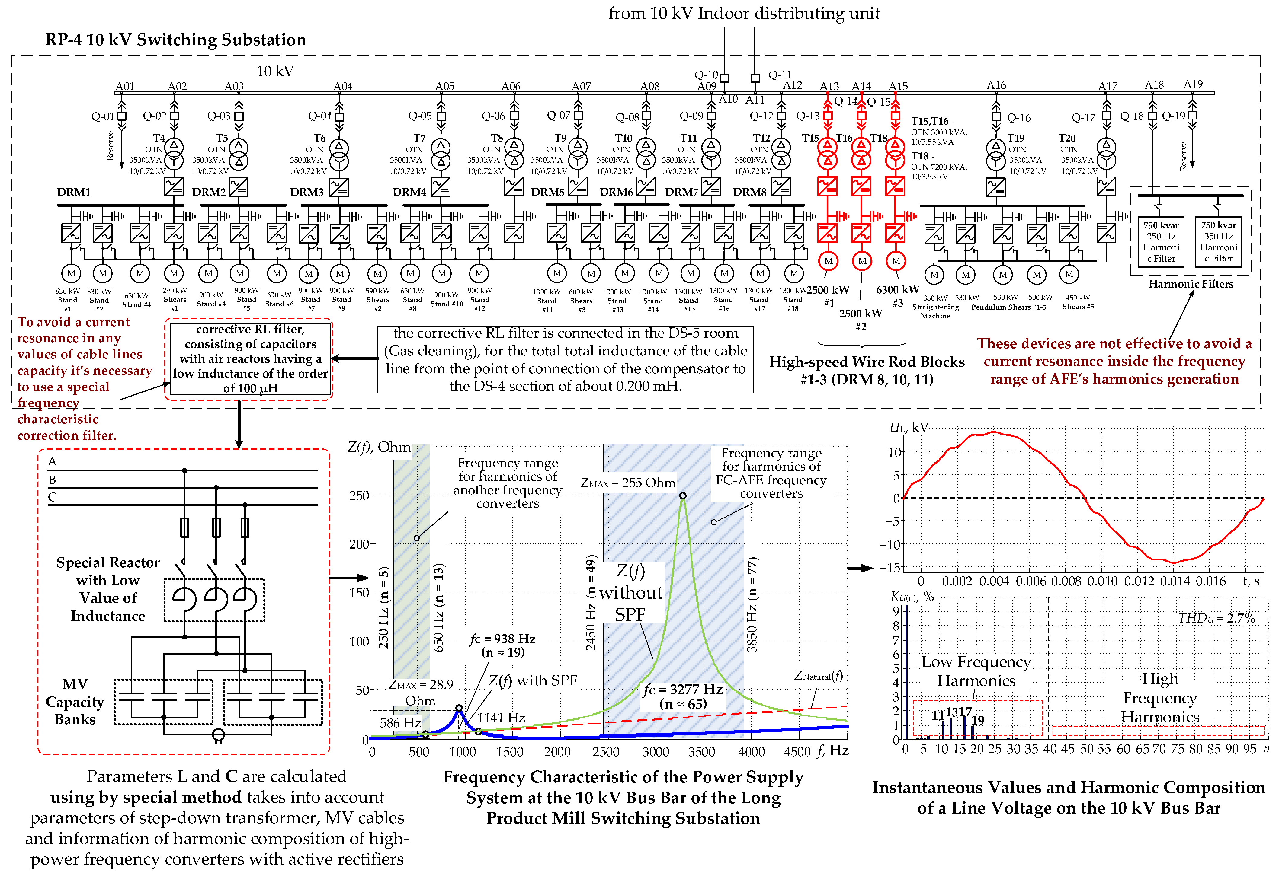
  • The PWM controller of the stand 1 electric drive AFE implements the PWM algorithm with selective elimination of harmonics 5 and 7 with 3 switchings over a quarter period. As a result, the harmonic range of the consumed current features the significant amplitude harmonics n = 11, 13, 19, 23, and 29 that fall into the main resonance region of the 10 kV grid frequency response relative to the 10 kV sections of MSDS and are amplified in phase and line grid voltages.
  • For the AFE electric drives of stands 2 and 4, we used the PWM algorithm with the selective elimination of harmonics n = 5, 7, 11, 13, 17, and 19 with 7 switchings over a quarter period. Considering that this FC-AFE has a 12-pulse power circuit, the use of the PWM algorithm with eliminated harmonics n = 5, 7, 17, and 19 in the current at the converter input is not feasible, as this does not allow for the automated elimination of these harmonics with the 12-pulse power supply circuit. In addition, the currents consumed from the 10 kV grid feature significant harmonics n = 23, 25, 35, and 37, and others that fall into the main resonance region in the 10 kV grid frequency response relative to the 10 kV sections of MSDS-2 with subsequent amplification in the grid voltage.
  • The consumed AFE current of stand 3 features harmonics n = 11, 13, 23, 25, 35, 37, etc., that are not typical of the 12-pulse rectification circuit. Since this AR uses PWM with seven switchings over a quarter period, the PWM settings used are not optimal.
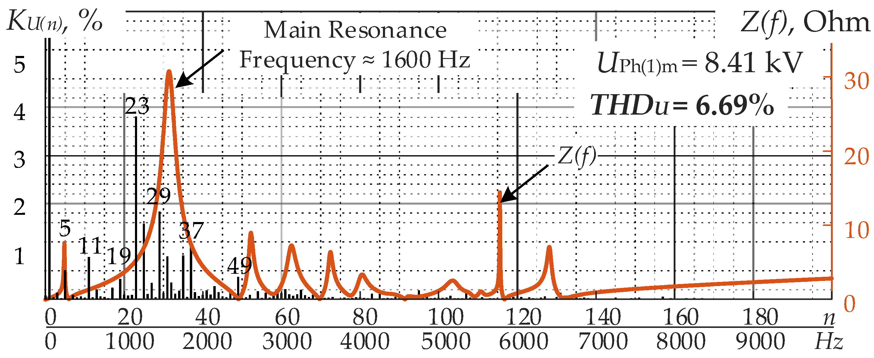
  • The AFE of the pulling reel electric drive uses PWM with selective harmonic elimination and nine switchings. The consumed power features harmonics n = 23, 29, etc., fall into the main resonance region in the 10 kV grid frequency response relative to the 10 kV sections of MSDS. Considering that, with nine switchings, it is possible to completely eliminate eight significant harmonics, n = 5, 7, 11, 13, 17, 19, 23, and 25. Thus, the current PWM settings are not optimal.
Based on the suggested approach to the definition of the optimal AFEPWM algorithm for the adaptation to the resonant phenomena, we suggested the following alterations to the PWM controller settings:
(1)
changing the number of IGCT switchings of the electric drive AFE in stand 1 from three to nine over a quarter period (changing the IGCT thyristor switching frequency from 150 Hz to 450 Hz);
(2)
keeping the number of IGCT switchings of the electric drive AFE in stands 2, 3, and 4 at seven per quarter period (350 Hz);
(3)
replacing the tables with thyristor switching angles in the PWM controllers of all AFE rectifiers with new ones, assuring the elimination of harmonics n = 5, 7, 11, 13, 17, 19, 23, and 25 for the AFE electric drive in stand 1 and the pulling reel, as well as harmonics n = 11, 13, 23, 25, 35, and 37 for the AFE electric drive in stands 2, 3, and 4.
After that, the AFE power module switching angle tables were calculated. These recommendations and new switching angle tables were sent to the representatives of the AFE manufacturer to implement the required changes.
After the adjustment of the AFEPWM settings following the recommendations, the 10 kV voltage curve shape improved in the factory distribution grid connected to MSDS, and the THDU was reduced by 47.4–82.3% depending on the power grid mode and the rolling mill operating mode (Figure 27a,b). In addition, the voltage shape in RP-19 improved significantly, and the THDU reduced by 23.9–51.4% (Figure 27c,d).
Apart from the suggested solution, we reviewed other EMC improvement methods for FC-AFEs and the power grid. These included the elimination of reactors in MSDS feeders, the disconnection of specific cable lines, the creation of a “dirty section”, the use of adjustment filters, and the combinations of those. The analysis carried out through imitation modeling showed that the most feasible EMC-improvement method for FC-AFEs at the Cherepovets Steel Mill is the use of the adaptive PWM algorithms. It is optimal both in terms of the technical effect and the required financial and time inputs.

7. Conclusions

In this research, we analyzed the existing EMC problems of high-power electric drives with FC-AFEs in 6–35 kV industrial grids. We described the problems relating to the quality of electricity that occur at existing production facilities due to the operation of electric drives with FC-AFEs. We discovered the mechanism behind the formation of significant voltage distortions in the medium-voltage factory distribution grid associated with the frequency response of the grid and the presence of non-compensated higher harmonics of current generated by FC-AFEs. We studied the potential solutions to these problems.
The analysis of the results obtained led to the following conclusions:
  • The 6–35 kV factory distribution grids that have medium-voltage high-power electric drives with FC-AFEs as consumers may bring about conditions for significant distortion of the voltage shape at the common coupling point for the consumers. These conditions include the presence of resonant phenomena in the power grid caused by the interactions between the inductance and capacity of specific elements, and the overlapping of the frequencies of the grid resonance and the higher harmonics generated by FC-AFEs.
  • These problems cannot be identified at the design stage of power grid and electric drive systems. Converter manufacturers keep silent about the real harmonic spectrum of currents and voltages at the FC-AFE input for promotion purposes. The harmonic components of currents and voltages are only accounted for until the 40–50th harmonics due to the shortcomings of the documents regulating the quality of electric power. The EMC problems of FC-AFEs only become obvious after the equipment commissioning.
  • The existing EMC-assurance methods for FC-AFEs and the power grid do not account for the non-linearity of the frequency response of the 6–35 kV grids. Therefore, the conventional methods of assuring the set electric power quality may be useless with FC-AFEs. One exception is the establishment of a “dirty section” within the company MSDS, which might not always be done at an operating production facility.
  • To improve the quality of 6–35 kV voltage at the common coupling point of consumers when FC-AFEs are operated in grids with resonant phenomena, we suggested the following alternative solutions: using specialized adjustment filters that help reduce the extreme in the frequency response of the 6–35 kV grids and shift it towards the main harmonic at the same time, and the use of the adaptive AFEPWM algorithms that eliminate or mitigate FC-AFE harmonics around the frequency response resonance. These EMC improvement methods for FC-AFEs and the power grid proved to be highly efficient for the active equipment of metal plants in Russia.

Author Contributions

Conceptualization, A.N.; methodology, A.N. and A.M.; software, I.G. and M.B.; validation, A.D.; formal analysis, M.A.; investigation, A.D. and M.A.; resources, A.N. and A.M.; data curation, A.N.; writing—original draft preparation, M.B.; writing—review and editing, I.G. and M.B.; visualization, A.D.; supervision, A.N.; project administration, A.M. and A.N. All authors have read and agreed to the published version of the manuscript.

Funding

This research was funded by the Russian Science Foundation, grant number 22-19-20069, https://rscf.ru/en/project/22-19-20069/.

Institutional Review Board Statement

Not applicable.

Informed Consent Statement

Not applicable.

Data Availability Statement

Not applicable.

Conflicts of Interest

The authors declare no conflict of interest.

Nomenclature

ACAlternative current
AFEActive front-end
CRMCold-rolling mill
DCDirect current
EFSElectric-furnace shop
EMCElectromagnetic compatibility
FC-AFEFrequency converter with active front-end
FPPCFixed pulse pattern control
FWBFast wire block
HSMHot strip mill
HSWRHigh speed wire rod
IGBTInsulated-gate bipolar transistor
IGCTIntegrated gate-commutated thyristor
LC circuitInductor and a capacitor electronic circuit
LPFLow-pass filter
LPRMLong product rolling mill
MSDSMain step-down substation
NPCNeutral point clamped
PIIdProportion-integral Id-current regulators
PIIqProportion-integral Iq-current regulators
PLLPhase-locked loop
PWMPulse width modulation
RLC circuitResistance, inductor and capacitor electronic circuit
SHEPWMSelective harmonic elimination pulse width modulation
SHMPWMSelective harmonic mitigation pulse width modulation
SPFSpecialized passive filters
TTransformer or thyristor
THDTotal harmonic distortion
THDITotal harmonic distortion of the current
THDUTotal harmonic distortion of the voltage
UPSUninterruptible power supply
VSIVoltage source inverter
abcFixed coordinate system
αjValue of j switching angle
dq0Rotating coordinate system
fCCutoff frequency
HjHarmonic amplitude of order j
I(1)mAmplitude value of the current first harmonic
idCurrent values on axes d
idrefSet current values on axes d
iqCurrent values on axes q
iqrefSet current values on axes q
kNumber of switchings
KI(n)Amplitude value of the n current harmonic
KU(n)Amplitude value of the n voltage harmonic
mModulation index
nHarmonic number
θAngle of vector in rotating coordinate system
θshiftShift angle
θrefReference angle
SgridGrid power
UABCrefReference value of AFE voltage
UAFEPhase-to-phase AFE voltage
UdVoltage vector on axes d
UDCDC-link voltage
UDCrefDC-link reference voltage
UgridPhase-to-phase grid voltage
ULLine voltage
UPhPhase voltage
UPh(1)mAmplitude value of the first phase voltage
UqVoltage vector on axes q
wtReference signal
Z(f)Frequency response of the grid
ZMAXPeak value of the frequency response
ZnaturalNatural frequency response

References

  1. O’Brien, K.; Teichmann, R.; Bernet, S. Active rectifier for medium voltage drive systems. In Proceedings of the IEEE Applied Power Electronics Conference and Exposition, Anaheim, CA, USA, 4–8 March 2001. [Google Scholar]
  2. Wu, B.; Narimani, M. High-Power Converters and AC Drives, 2nd ed.; Wiley-IEEE Press: Hoboken, NJ, USA, 2017. [Google Scholar]
  3. Mohammed, S.A.; Abdel-Moamen, M.A.; Hasanin, B. A review of the state-of-the-art of power electronics for power system applications. Int. J. Electron. Commun. Eng. Res. 2013, 1, 43–52. [Google Scholar]
  4. Maswood, I.; Rashid, M.H.; Jian, L. Optimal PWM-SHE switching on NPC inverter: A winning match for high power conversion. Electr. Power Syst. Res. 1998, 48, 19–24. [Google Scholar] [CrossRef]
  5. Konstantinou, G.; Agelidis, V.G. Bipolar switching waveform: Novel solution sets to the selective harmonic elimination problem. In Proceedings of the IEEE International Conference on Industrial Technology, Viña del Mar, Chile, 14–17 March 2010. [Google Scholar]
  6. Islam, J.; Meraj, S.T.; Masaoud, A.; Mahmud, M.A.; Nazir, A.; Kabir, M.A.; Hossain, M.M.; Mumtaz, F. Opposition-based quantum bat algorithm to eliminate lower-order harmonics of multilevel inverters. IEEE Access 2021, 9, 103610–103626. [Google Scholar] [CrossRef]
  7. Dahidah, M.S.A.; Agelidis, V.G. Hybrid genetic algorithm approach for selective harmonic control. Energy Convers. Manag. 2008, 49, 131–142. [Google Scholar] [CrossRef]
  8. Li, L.; Czarkowski, D.; Yaguang, L.; Pillay, P. Multilevel selective harmonic elimination PWM technique in series-connected voltage inverters. IEEE Trans. Ind. Appl. 2000, 36, 160–170. [Google Scholar] [CrossRef]
  9. Wang, Y.; Wen, X.; Zhao, F.; Guo, X. Selective harmonic elimination PWM technology applied in PMSMs. In Proceedings of the IEEE Vehicle Power and Propulsion Conference, Seoul, Korea, 9–12 October 2012. [Google Scholar]
  10. Moeini, A.; Zhao, H.; Wang, S. A current-reference-based selective harmonic current mitigation PWM technique to improve the performance of cascaded H-bridge multilevel active rectifiers. IEEE Trans. Ind. Electron. 2018, 65, 727–737. [Google Scholar] [CrossRef]
  11. Turnbull, F.G. Selected harmonic reduction in static D-C–A-C inverters. IEEE Trans. Commun. 1964, 83, 374–378. [Google Scholar] [CrossRef]
  12. Agelidis, V.G.; Balouktsis, A.; Balouktsis, I.; Cossar, C. Multiple sets of solutions for harmonic elimination PWM bipolar waveforms: Analysis and experimental verification. IEEE Trans. Power Electron. 2006, 21, 415–421. [Google Scholar] [CrossRef] [Green Version]
  13. Chen, J.; Liang, T.; Wang, S. A Novel Design and Implementation of Programmed PWM to Eliminate Harmonics. In Proceedings of the IEEE International Conference on Industrial Electronics, Control, Instrumentation, and Automation, Raleigh, NC, USA, 6–10 November 2005. [Google Scholar]
  14. Enjeti, P.N.; Enjeti, P.N.; Lindsay, J.F. Solving nonlinear equations of harmonic elimination PWM in power control. IEEE Electron. Lett. 1987, 23, 656–657. [Google Scholar] [CrossRef]
  15. Ahmad, S.; Iqbal, A.; Ali, M.; Rahman, K.; Ahmed, A.S. A fast convergent homotopy perturbation method for solving selective harmonics elimination PWM problem in multi level inverter. IEEE Access 2021, 9, 113040–113051. [Google Scholar] [CrossRef]
  16. Tolbert, L.M.; Chiasson, J.N.; Du, Z.; McKenzie, K.J. Elimination of harmonics in a multilevel converter with non-equal DC sources. IEEE Trans. Ind. Appl. 2005, 41, 75–82. [Google Scholar] [CrossRef]
  17. Chen, J.W.; Liang, T.J. A novel algorithm in solving nonlinear equations for programmed PWM inverter to eliminate harmonics. In Proceedings of the IECON 23rd International Conference on Industrial Electronics, Control, and Instrumentation, New Orleans, LA, USA, 14 November 1997. [Google Scholar]
  18. Bowes, S.R.; Clark, P.R. Simple microprocessor implementation of new regular-sampled harmonic elimination PWM techniques. IEEE Trans. Ind. Appl. 1992, 28, 89–95. [Google Scholar] [CrossRef]
  19. Bowes, S.R.; Clark, P.R. Regular-sampled harmonic-elimination PWM control of inverter drives. IEEE Trans. Power Electron. 2002, 10, 521–531. [Google Scholar] [CrossRef]
  20. Bowes, S.R.; Grewal, S.; Holliday, D. Single-phase three-level regular-sampled selective harmonic elimination PWM. IEE Proc. Electr. Power Appl. 2002, 148, 155–161. [Google Scholar] [CrossRef]
  21. Chiasson, J.N.; Tolbert, L.M.; McKenzie, K.J.; Du, Z. A complete solution to the harmonic elimination problem. IEEE Trans. Power Electron. 2004, 19, 491–499. [Google Scholar] [CrossRef]
  22. Cetin, A.; Ermi, M. VSC-based D-STATCOM with selective harmonic elimination. IEEE Trans. Ind. Appl. 2009, 45, 1000–1015. [Google Scholar] [CrossRef]
  23. Ran, L.; Holdsworth, L.; Putrus, G.A. Dynamic selective harmonic elimination of a three level inverter used for static VAr compensation. IET Gener. Transm. Distrib. 2002, 149, 83–89. [Google Scholar] [CrossRef]
  24. Zhou, H.; Li, Y.; Zargari, N.R.; Cheng, Z.; Ni, R.; Zhang, Y. Selective harmonic compensation (SHC) PWM for grid-interfacing high-power converters. IEEE Trans. Power Electron. 2014, 29, 1118–1127. [Google Scholar] [CrossRef]
  25. Zhou, Z.; Zhong, Y.; Gao, H.; Yuan, L.; Lu, T. Hybrid selective harmonic PWM for common-mode voltage reduction in three-level neutral-point-clamped inverter for variable speed induction motor. IEEE Trans. Power Electron. 2012, 27, 1152–1158. [Google Scholar] [CrossRef]
  26. Narimani, M.; Mochopoulos, G. Three-phase multimodule VSIs using SHE-PWM to reduce zero-sequence circulating current. IEEE Trans. Ind. Electron. 2014, 61, 1659–1668. [Google Scholar] [CrossRef]
  27. Fei, W.; Ruan, X.; Wu, B. A generalized formulation of quarter-wave symmetry SHE-PWM problems for multilevel inverters. IEEE Trans. Power Electron. 2009, 24, 1758–1766. [Google Scholar] [CrossRef]
  28. Eryong, G.; Pinggang, S.; Eryong, G.; Manyuan, Y.; Bin, W. Selective harmonic elimination techniques for multilevel cascaded H-bridge inverters. In Proceedings of the IEEE International Conference on Power Electronics and Drives Systems, Kuala Lumpur, Malaysia, 28 November–1 December 2005. [Google Scholar]
  29. Du, Z.; Tolbert, L.M.; Chiasson, J.N. Active harmonic elimination for multilevel converters. IEEE Trans. Power Electron. 2006, 21, 459–469. [Google Scholar]
  30. Konstantinou, G.; Ciobotaru, M.; Agelidis, V. Selective harmonic elimination pulse-width modulation of modular multilevel converters. IET Power Electron. 2013, 6, 96–107. [Google Scholar] [CrossRef]
  31. Aguilera, R.P.; Acuña, P.; Lezana, P.; Konstantinou, G.; Wu, B.; Bernet, S.; Agelidis, V.G. Selective Harmonic Elimination Model Predictive Control for Multilevel Power Converters. IEEE Trans. Power Electron. 2017, 32, 2416–2426. [Google Scholar] [CrossRef] [Green Version]
  32. Watson, J.; Wheeler, P.W.; Clare, J.C. A complete harmonic elimination approach to DC link voltage balancing for a cascaded multilevel rectifier. IEEE Trans. Ind. Electron. 2007, 54, 2946–2953. [Google Scholar] [CrossRef]
  33. Guzman, J.I.; Melin, P.E.; Espinoza, J.R.; Moran, L.A.; Baier, C.R.; Munoz, J.A.; Guinez, G.A. Digital implementation of selective harmonic elimination techniques in modular current source rectifier. IEEE Trans. Ind. Inform. 2013, 9, 1167–1177. [Google Scholar] [CrossRef]
  34. Ahmadi, D.; Wang, J. Online selective harmonic compensation and power generation with distributed energy resources. IEEE Trans. Power Electron. 2014, 29, 3738–3746. [Google Scholar] [CrossRef]
  35. Portillo, R.; Sharifzadeh, M.; Vahedi, H.; Franquelo, L.G.; Al-Haddad, K. Improved Hybrid SHM-SHE Modulation Technique for Four-Leg Three-Level NPC Inverters. In Proceedings of the IECON 2015-41st Annual Conference of the IEEE Industrial Electronics Society, Yokohama, Japan, 9–12 November 2015. [Google Scholar]
  36. Sharifzadeh, M.; Vahedi, H.; Portillo, R.; Franquelo, L.G.; Al-Haddad, K. Selective harmonic mitigation based self-elimination of triplen harmonics for single-phase five-level inverters. IEEE Trans. Power Electron. 2019, 34, 86–96. [Google Scholar] [CrossRef]
  37. Campos-Gaona, D.; Peña-Alzola, R.; Monroy-Morales, J.L.; Ordonez, M.; Anaya-Lara, O.; Leithead, W.E. Fast selective harmonic mitigation in multifunctional inverters using internal model controllers and synchronous reference frames. IEEE Trans. Ind. Electron. 2017, 64, 6338–6349. [Google Scholar] [CrossRef] [Green Version]
  38. Zhou, K.; Yang, Y.; Blaabjerg, F.; Wang, D. Optimal selective harmonic control for power harmonics mitigation. IEEE Trans. Ind. Electron. 2015, 62, 1220–1230. [Google Scholar] [CrossRef] [Green Version]
  39. Schettino, G.; Colak, I.; Tommaso, A.O.D.; Miceli, R.; Viola, F. Innovative Computational Approach to Harmonic Mitigation for Seven-Level Cascaded H-Bridge Inverters. In Proceedings of the 15th International Conference on Ecological Vehicles and Renewable Energies, Monte-Carlo, Monaco, 1–7 September 2020. [Google Scholar]
  40. Moeini, A.; Iman-Eini, H.; Bakhshizade, M. Selective harmonic mitigation-pulse-width modulation technique with variable DC-link voltages in single and three-phase cascaded H-bridge inverters. IET Power Electron. 2014, 7, 924–932. [Google Scholar] [CrossRef] [Green Version]
  41. Aggrawal, H.; Leon, J.I.; Franquelo, L.G.; Kouro, S.; Garg, P.; Rodriguez, J. Model Predictive Control Based Selective Harmonic Mitigation Technique for Multilevel Cascaded H-Bridge Converters. In Proceedings of the IECON 2011-37th Annual Conference of the IEEE Industrial Electronics Society, Melbourne, Australia, 7–10 November 2011. [Google Scholar]
  42. Steczek, M.; Chudzik, P.; Szelag, A. Combination of SHE- and SHM-PWM techniques for VSI DC-link current harmonics control in railway applications. IEEE Trans. Ind. Electron. 2017, 64, 7666–7678. [Google Scholar] [CrossRef]
  43. Hashir, S.; Francis, J.; Sreepriya, R. A novel hybrid PWM method for DC-link voltage balancing in a three level neutral point clamped inverter. In Proceedings of the International Conference on Power, Signals, Control and Computation, Thrissur, India, 6–10 January 2018. [Google Scholar]
  44. Farhan, B. Space Vector Pulse Width Modulation Technique Based Design and Simulation of a Three-Phase Voltage Source Converter System. Int. J. Energy Power Eng. 2014, 8, 1458–1462. [Google Scholar]
  45. Jiang, W.; Du, S.; Chang, L.; Zhang, Y.; Zhao, Q. Hybrid PWM strategy of SVPWM and VSVPWM for NPC three level voltage-source inverter. IEEE Trans. Power Electron. 2010, 25, 2607–2619. [Google Scholar] [CrossRef]
  46. Pontt, J.; Rodriguez, J.; Martin, S. Resonance mitigation and dynamical behavior of systems with harmonic filters for improving reliability in mining plants. In Proceedings of the IEEE Industry Applications Conference Forty-First IAS Annual Meeting, Tampa, FL, USA, 8–12 October 2006. [Google Scholar]
  47. Blooming, T.M.; Carnovale, D.J. Application of IEEE STD 519-1992 Harmonic Limits. In Proceedings of the Annual Pulp and Paper Industry Technical Conference, Appleton, WI, USA, 18–23 June 2006. [Google Scholar]
  48. Radionova, L.V.; Chernyshev, A.D. Mathematical description of AFE rectifier closed loop system. Procedia Eng. 2015, 129, 16–21. [Google Scholar] [CrossRef] [Green Version]
  49. Yamanaka, K.; Yamada, K.; Kumagae, A.; Terada, T. Three-Level Neutral Point Clamping Type Inverter Circuit. U.S. Patent 06,226,192, 1 May 2001. [Google Scholar]
  50. Abu-Rub, H.; Bayhan, S.; Moinoddin, S.; Malinowski, M.; Guzinski, J. Medium-Voltage Drives: Challenges and existing technology. IEEE Power Electron. Mag. 2016, 3, 29–41. [Google Scholar] [CrossRef]
  51. Jose, I.L.; Leon, J.I.; Kouro, S.; Franquelo, L.G.; Rodriguez, J.; Wu, B. The Essential Role and the Continuous Evolution of Modulation Techniques for Voltage-Source Inverters in the Past, Present, and Future Power Electronics. IEEE Trans. Ind. Electron. 2018, 63, 2688–2701. [Google Scholar] [CrossRef]
  52. Wu, X.; Tan, G.; Yao, G.; Sun, C.; Liu, G. A hybrid PWM strategy for three-level inverter with unbalanced DC links. IEEE J. Emerg. Sel. Top. Power Electron. 2018, 6, 1–15. [Google Scholar] [CrossRef]
  53. Holtz, J.; Salama, S.F. Megawatt GTO-inverter with three-level PWM control and regenerative snubber circuits. In Proceedings of the 19th Annual IEEE Power Electronics Specialists Conference, Kyoto, Japan, 11–14 April 1988. [Google Scholar]
  54. Rodriguez, J.; Franquelo, L.G.; Kouro, S.; Leon, J.I.; Portillo, R.C.; Prats, M.A.M.; Perez, M.A. Multilevel converters: An enabling technology for high-power applications. Proc. IEEE 2009, 97, 1786–1817. [Google Scholar] [CrossRef] [Green Version]
  55. Holmes, D.G.; Lipo, T.A. Pulse Width Modulation for Power Converters: Principles and Practice, 1st ed.; Wiley-IEEE Press: Hoboken, NJ, USA, 2003. [Google Scholar]
  56. Li, Y.; Wu, B. A novel dc voltage detection technique in the CHB inverter-based STATCOM. IEEE Trans. Power Deliv. 2008, 23, 1613–1619. [Google Scholar]
  57. Zhang, F.; Yan, Y. Selective harmonic elimination PWM control scheme on a three phase four-leg voltage source inverter. IEEE Trans. Power Electron. 2009, 24, 1682–1689. [Google Scholar] [CrossRef]
  58. Lisovskay, T.A.; Maklakov, A.S.; Lisovsky, R.A.; Jing, T. Linearization small deviation model of active front end rectifier. In Proceedings of the Russian Workshop on Power Engineering and Automation of Metallurgy Industry: Research & Practice, Magnitogorsk, Russia, 25–26 September 2020. [Google Scholar]
  59. Maklakov, A.S.; Jing, T.; Radionov, A.A.; Gasiyarov, V.R.; Lisovskaya, T.A. Finding the best programmable PWM pattern for three-level active front-ends at 18-pulse connection. Machines 2021, 9, 127. [Google Scholar] [CrossRef]
  60. Jing, T.; Maklakov, A.S.; Radionov, A.A. Two Selective Harmonic Control Techniques Applied in 10Kv Grid with Three-Level NPC Inverter. In Proceedings of the Russian Workshop on Power Engineering and Automation of Metallurgy Industry: Research & Practice, Magnitogorsk, Russia, 4–5 October 2019. [Google Scholar]
  61. Azeddine, D.; Senior, M.A. Space vector modulation based tree-level PWM Rectifier under Simple Sliding Mode Control Strategy. Energy Power Eng. 2013, 5, 28–35. [Google Scholar]
  62. Agelidis, V.G.; Balouktsis, A.; Balouktsis, I. On applying a minimization technique to the harmonic elimination PWM control: The bipolar waveform. IEEE Trans. Power Electron. 2004, 2, 41–44. [Google Scholar] [CrossRef]
  63. Kouro, S.; Rocca, B.L.; Cortes, P.; Alepuz, S.; Bin, W.; Rodriguez, J. Predictive Control Based Selective Harmonic Elimination with Low Switching Frequency for Multilevel Converters. In Proceedings of the IEEE Energy Conversion Congress and Exposition, San Jose, CA, USA, 20–24 September 2009. [Google Scholar]
  64. Patil, S.D.; Kadu, A.; Dhabe, P. Improved Control Strategy for Harmonic Mitigation in Multilevel Inverter. In Proceedings of the 5th International Conference on Intelligent Computing and Control Systems, Madurai, India, 6–8 May 2021. [Google Scholar]
  65. Pontt, J.; Rodriguez, J.; Huerta, R. Mitigation of non-eliminated harmonics of SHEPWM three-level multipulse three-phase active front end converter with low switching frequency for meeting standard IEEE519-92. IEEE Trans. Power Electron. 2004, 19, 1594–1599. [Google Scholar] [CrossRef]
  66. Cao, J.; Xie, S.; Xu, J. Research on A High Power Inverter with Low Frequency Modulation Index by Selective Harmonic Mitigation Technique. In Proceedings of the 9th International Conference on Power Electronics and ECCE Asia, Seoul, Korea, 1–5 June 2015. [Google Scholar]
  67. Marzoughi, A.; Imaneini, H. An Optimal Selective Harmonic Mitigation for Cascaded H-Bridge Converters. In Proceedings of the 11th International Conference on Environment and Electrical Engineering, Venice, Italy, 18–25 May 2012. [Google Scholar]
  68. Nikolaev, A.A.; Bulanov, M.V.; Antropova, L.I. Ways to ensure electromagnetic compatibility of powerful frequency converters in internal power supply systems of industrial enterprises in the presence of resonance phenomena. In Proceedings of the International Conference on Industrial Engineering, Applications and Manufacturing, Sochi, Russia, 25–29 March 2019. [Google Scholar]
  69. Nikolaev, A.A.; Bulanov, M.V.; Shakhbieva, K.A. New Method of Industrial Power Supply Systems’ Resonances Diagnosis by Using Test Influences of Frequency Converters with Active Rectifier. In Proceedings of the IEEE Russian Workshop on Power Engineering and Automation of Metallurgy Industry: Research & Practice, Magnitogorsk, Russia, 4–5 October 2019. [Google Scholar]
  70. Nikolaev, A.A.; Maklakov, A.S.; Gilemov, I.G.; Bulanov, M.V. Experimental Studies of Power Quality in the 34.5 kV Network of MMK Metalurji During Operation of Electric Drives with Active Rectifiers. In Proceedings of the International Ural Conference on Electrical Power Engineering, Magnitogorsk, Russia, 23–25 September 2022. [Google Scholar]
  71. Nikolaev, A.A.; Gilemov, I.G.; Bulanov, M.V.; Kosmatov, V.I. Providing Electromagnetic Compatibility of High-Power Frequency Converters with Active Rectifiers at Internal Power Supply System of Cherepovets Steel Mill. In Proceedings of the International Scientific Technical Conference Alternating Current Electric Drives, Ekaterinburg, Russia, 1–8 May 2021. [Google Scholar]
  72. Nikolaev, A.A.; Afanasev, M.Y.; Bulanov, M.V. Application of a Specialized Passive Filter to Correct the Frequency Response of the Supply Network in order to Eliminate the Negative Impact of Resonance Phenomena. In Proceedings of the Russian Workshop on Power Engineering and Automation of Metallurgy Industry: Research and Practice, Magnitogorsk, Russia, 25–26 September 2020. [Google Scholar]
  73. Rodríguez, J.R.; Pontt, J.; Huerta, R.; Alzamora, G.; Becker, N.; Kouro, S.; Cortes, P.; Lezana, P. Resonances in a high-power active-front-end rectifier system. IEEE Trans. Power Electron. 2005, 52, 482–488. [Google Scholar] [CrossRef]
  74. Pontt, J.A.; Rodríguez, J.R.; Liendo, A.; Newman, P.; Holtz, J.; San Martin, J.M. Network-Friendly Low-Switching-Frequency Multipulse High-Power Three-Level PWM Rectifier. IEEE Trans. Ind. Electron. 2009, 56, 4, 1254–1262. [Google Scholar] [CrossRef]
  75. Hoevenaars, A.; Farbis, M.; McGraw, M. Active harmonic mitigation: What the manufacturers don’t tell you. IEEE Ind. Appl. Mag. 2020, 62, 41–51. [Google Scholar] [CrossRef]
  76. Nikolaev, A.A.; Bulanov, M.V.; Shakhbieva, K.A. Development of improved PWM algorithm of active rectifier with function of resonant phenomena adaptation in electrical networks of medium voltage. In Proceedings of the International Conference on Industrial Engineering, Applications and Manufacturing, Sochi, Russia, 18–22 May 2020. [Google Scholar]
  77. Nikolaev, A.A.; Bulanov, M.V.; Shakhbieva, K.A. Quality Improvement of Electric Power in the Intra-factory Electric Networks through the Use of PWM Algorithm Selective Harmonic Mitigation. In Proceedings of the Russian Workshop on Power Engineering and Automation of Metallurgy Industry: Research and Practice, Magnitogorsk, Russia, 25–26 September 2020. [Google Scholar]
Figure 1. The simplified FC-AFE circuit.
Energies 16 00293 g001
Figure 2. The 6-pulse circuit for connecting the FC-AFE.
Energies 16 00293 g002
Figure 3. The 12-pulse circuits based on a net-side phase-shift transformer with series-connected primary windings.
Energies 16 00293 g003
Figure 4. The 18-pulse grid connection circuit based on a multi-winding phase-shift transformer with a series connection of primary windings.
Energies 16 00293 g004
Figure 5. The function diagram of the AFE control system.
Energies 16 00293 g005
Figure 6. The structural diagram of PWM Fixed Pulse Pattern Control.
Energies 16 00293 g006
Figure 7. The dependency of the switching angles and the modulation coefficient.
Energies 16 00293 g007
Figure 8. The structural diagram of Selective Harmonic Elimination Pulse Width Modulation.
Energies 16 00293 g008
Figure 9. Measuring complexes to analyze the power quality in the internal power grid of metallurgical enterprises based on high-speed multichannel electrical signal recorders: (a) ProsoftSystem ‘EER-3’ (Russian «PЭC-3 Пpocoφт-Cиcтeмы») (sampling frequency of 100 kHz; instrument error, ±1%) and National Instruments NI-USB-6251 (sample rate maximum, 1.25 MS/s; accuracy, ±1%); (b) power quality analyzers Elspec G4420 (voltage harmonics up to 255; uncertainty, 0.1% of Nominal); (c) Fluke 435 (sampling frequency of 200 kS/s) and Fluke i5s current clamps (useable frequency 40 Hz to 5 kHz; accuracy, ±1%).
Energies 16 00293 g009
Figure 10. The grid diagram for the key electric drives of the bar mill.
Energies 16 00293 g010
Figure 11. The immediate values of the line voltage in the 10 kV buses (a) and their harmonic spectrum (b).
Energies 16 00293 g011
Figure 12. The power single-line diagram for the key electric drives of the hot-rolling mill.
Energies 16 00293 g012
Figure 13. The immediate values of the line voltage in the 34.5 kV buses (a) and their harmonic spectrum (b).
Energies 16 00293 g013
Figure 14. The grid diagram for the key electric drives of the cold-rolling mill.
Energies 16 00293 g014
Figure 15. The instant values of phase voltage in 10 kV buses of MSDS (a) and their harmonic spectrum and the frequency response of the grid (b).
Energies 16 00293 g015
Figure 16. The simplified power grid for the bar mill electric drives.
Energies 16 00293 g016
Figure 17. The instant phase voltage values in the 10 kV buses (a) and their harmonic spectrum and grid frequency response (b); instant 6.3 MW current values for a Fast Wire Block’s Electric Drive (c) and their harmonic spectrum (d).
Energies 16 00293 g017
Figure 18. Simplified single-line diagram for the power grid of the Los Pelambres mine.
Energies 16 00293 g018
Figure 19. The frequency response of the Los Pelambres mine grid relative to Bus 10.
Energies 16 00293 g019
Figure 20. An example of using a “dirty section” to assure the electromagnetic compatibility of FC-AFEs and sensitive power consumers.
Energies 16 00293 g020
Figure 21. The main harmonic filter types: (a) single-tuned filter or specialized passive filter; (b) double-tuned filter; (c) high-pass filter; (d) C-type high-pass filter.
Energies 16 00293 g021
Figure 22. The comparison of frequency characteristics and voltage quality on the 10 kV bus bar at the long product mill’s switching substation: (a) the frequency response of the 10 kV grid without SPF; (b) the instant line voltage values without SPF; (c) the harmonic spectrum of line voltage without SPF; (d) the frequency response of the 10 kV grid with SPF; (e) the instant line voltage values with SPF; (f) the harmonic spectrum of line voltage with SPF.
Energies 16 00293 g022
Figure 23. The adjustment of the frequency response of the power supply system by applying an SPF.
Energies 16 00293 g023
Figure 24. Specialized passive filter.
Energies 16 00293 g024
Figure 25. The results of using (a) Fixed Pulse Pattern Control; (b) SHEPWM (53, 55, 59, 61); (c) SHMPWM (47–61) when there is resonance in the medium-frequency region.
Energies 16 00293 g025
Figure 26. The frequency response and the spectral analysis of voltage in the sections of the MSDS 10 kV distribution device.
Energies 16 00293 g026
Figure 27. The comparison of the phase voltage oscillograms of the MSDS 10 kV grid (a,b) and the RP-19 substation (c,d) and their spectral analysis: (a,c) before using adaptive AFEPWM; (b,d) after using adaptive AFEPWM.
Energies 16 00293 g027
Table 1. Possible states of three-level AFE power modules.
Phase A ArmPhase B ArmPhase C Arm
T1ClosedOpenOpenT5ClosedOpenOpenT9ClosedOpenOpen
T2ClosedClosedOpenT6ClosedClosedOpenT10ClosedClosedOpen
T3OpenClosedClosedT7OpenClosedClosedT11OpenClosedClosed
T4OpenOpenClosedT8OpenOpenClosedT12OpenOpenClosed
UAFEa+UDC/20−UDC/2UAFEb+UDC/20−UDC/2UAFEc+UDC/20−UDC/2
StatusPONStatusPONStatusPON
Table 2. Voltage quality indicators in metal plant power supply systems with FC-AFEs and resonant phenomena.
CompanyTHDU, %Zpeak, Ohmsfpeak, Hz
Balakovo Steel Factory [69]10.262553277
MMK Metalurji [70]12.365982550
Cherepovets Steel Mill [71]7.1431.11500
Abinsk Electric Steel Works [72]13.722672850
Los Pelambres copper mine [73]10.51134.71300
Disclaimer/Publisher’s Note: The statements, opinions and data contained in all publications are solely those of the individual author(s) and contributor(s) and not of MDPI and/or the editor(s). MDPI and/or the editor(s) disclaim responsibility for any injury to people or property resulting from any ideas, methods, instructions or products referred to in the content.

