Article

De-Loaded Technique Enhanced by Fuzzy Logic Controller to Improve the Resilience of Microgrids Based on Wind Energy and Energy Storage Systems

1
Engineering for Smart and Sustainable Systems Research Center, Mohammadia School of Engineers, Mohammed V University in Rabat, Rabat 10090, Morocco
2
Research, Development and Innovation Laboratory, Mundiapolis University, Casablanca 20180, Morocco
3
Department of Electrical and Control Engineering, Mokpo National University, Mokpo 58554, Republic of Korea
*
Author to whom correspondence should be addressed.
Energies 2023, 16(1), 291; https://doi.org/10.3390/en16010291
Submission received: 25 October 2022 / Revised: 25 November 2022 / Accepted: 20 December 2022 / Published: 27 December 2022
(This article belongs to the Special Issue Towards Intelligent, Reliable and Flexible Stand-Alone Microgrids)

Abstract

:
Wind turbine generators (WTGs) are highly sensitive to the disturbances of the grid and tend to disconnect quickly during a voltage dip (when the voltage value is less than 80% of the nominal voltage) or when the frequency is greatly changed. As an increasing number of permanent magnet synchronous generators (PMSGs) are incorporated into the modern power grid, system operators expect PMSG-WT to play an active role in low-voltage ride-through (LVRT) and primary frequency regulation (PFR). Consequently, PMSG-WTs must be capable of supplying additional active power in response to changes in system voltage and frequency. In this context, a new de-loaded technique enhanced by a fuzzy-logic controller is suggested to develop the PMSG-pitch angle control (PMSG-PAC). The studied MG consists of a wind farm (WF), variable load, and a battery energy storage system (BESS). The WF contains five PMSG-WTs which are considered to be the principal resource. The proposed DT-FLC ensures maximum aerodynamic reserve power for the plant, enhances its capability to regulate the PAC, adjusts the WTG drop in response to the wind speed, and increases the resilience of the PMSG-WT in the presence of low voltage. Moreover, the PFR is significantly improved in terms of controlling the PAC (−0.0007 Hz) which meets the frequency maximum droop recommended by the IEEE Std 1547-2018 and the Moroccan grid code, −3 Hz and −2.5 Hz, respectively.

1. Introduction

1.1. General Contexte

A microgrid is a smart grid that uses local renewable energy production (wind, solar, hydro, etc.) to power the load(s). As the energy data is transmitted, the microgrid (MG) also transmits data on consumption, production, and storage. The MG energy management system enables the optimization of energy consumption and the electricity bill of the load-demand, as well as the storage and control of energy in real-time.
Wind energy (WE) has been extensively exploited during the past decades [1]. Nowadays, wind energy is usually the most cost-effective source of sustainable energy [2]. It also makes a substantial contribution to MGs and utility grids (UGs) [3,4]. In the field of variable speed wind turbines (VS-WTs), permanent magnet synchronous generator WTs (PMSG-WTs) are widely used due to their quicker control reactions in comparison to other technologies [5]. They have an extensive operation area as they only employ power converters, such as generator-side converters (rectifiers) and grid-side converters (inverters).
To enhance the MG when a fault occurs and manage the power generation intermittency, a battery energy storage system (BESS) is proposed. In sustainable MGs, BESSs are an important element [6]. They provide charging and discharging feature that are tailored to grid-fault events, weather conditions, and utility grid (UG) electricity prices [7]. They recover the discontinuity of the renewable energy generators and stabilize the frequency oscillation of their output power by emulating inertia [8].
Of several controllers, the fuzzy-logic controller (FLC) is the most widely used controller for MG control strategies based on renewable energy resources due to advantages that include improving system stability, regulating bus voltage, adjusting output power, and offering quick battery charging and discharging actions. In addition, economically, FLC is an inexpensive controller [9,10]. Furthermore, to reduce DC-link voltage fluctuations and guarantee an active power reserve margin, the PMSG must function in the de-loaded mode rather than the maximum power point tracking (MPPT) mode [3]. In addition, the de-loaded technique (DT) can keep part of the active power in real-time to meet the load demand and to ride through the voltage sag by controlling the angular rotation speed (ARS). For this reason, during depressing frequency and voltage conditions, a DT-FLC is proposed due to the complementarity between the advantages of both the de-loaded technique and the FLC. In this study, the optimal PMSG torque is estimated from the generator speed based on the WT model to achieve an optimal power reserve from the greatest possible WTG input power.

1.2. Related Works

A variety of research studies have been conducted to tackle the aforementioned problem. For instance, the authors in [4] investigated the LVRT requirement using the FLC and the MPPT mode. An FLC was designed with the aim of smoothing fluctuations in wind power. The MPPT mode was used to control the stator side converter. However, according to the same paper, since wind velocity varies strongly, the MPPT mode also produces significantly variable power.
In [5], de-loaded-LVRT control for the PMSG was investigated. The de-loaded technique was used to resolve the reserve energy limitation issue during a grid fault. However, by regulating rotor speed, the de-loaded control approach can sometimes result in loss of system control.
Authors in [3,11] employed an artificial neural network (ANN) to control and enhance microgrid LVRT functionality due to its ability to approximate complicated systems and increase control scheme performance. ANNs have the potential to implement nonlinear system identification and control. Nevertheless, uncertainties in the ANN parameters result in the limited performance of this control.
In [12], the authors proposed a coordinated control approach for WTGs and a supercapacitor energy storage system (ESS). Inertial control was developed with the generator torque limit, whereas to compensate for the active power shortage during the turbine rotor recovery phase, ESS liberates its energy. The fatigue, aerodynamic, structure, and turbulence (FAST) algorithm was used to describe the WTG, which determines the WT-mechanical torque and handles electromechanical interactions in the wind energy system. During frequency supports, a damping controller was added to the inertial control to prevent strong mechanical oscillations in the WT. Furthermore, the stability study revealed that the WTG and ESS stability was enhanced. However, the authors in this paper did not discuss the participation of their proposed control in the LVRT requirements.
The authors in [4] suggested an FLC-based strategy for a full-converter WTG linked with an energy storage device of the supercapacitor. The FLC was expected to smooth out wind power variations while simultaneously maintaining a supercapacitor energy reserve for short-term grid interruptions. The fuzzy method was rigorously evaluated and compared to a traditional power smoothing strategy as well as the scenario without an ESS. They found that the FLC improves wind power smoothing and regulates the state of charge (SoC) of the supercapacitor during faults in the simulated microgrid. The WTG and MG exploitation were significantly enhanced by decreasing power oscillation and ESS performance to meet the LVRT requirement. However, results show that the active power injected into the grid was still disturbed.

1.3. The Main Contribution

This paper’s main contribution ensures the optimization of a de-loaded technique improved by an FLC to enhance the performance of the standard LVRT control and PFR. In this context, the benefits of the proposed method are summarized as follows:
  • ― Developing a flexible DT-FLC to improve the traditional LVRT control and PFR;
  • ― Limiting the low frequency by respecting the frequency limit droop given by the IEEE standard (IEEE Std 1547–2018);
  • ― Designing an MG which can successfully participate in the auxiliary services, mainly voltage and frequency control;
  • ― Minimizing the DC-link voltage oscillations under unbalanced microgrid conditions, which allows protection of the rectifier and the inverter.

1.4. Paper Arrangement

The rest of this paper is structured as follows. The mathematical modeling of the microgrid is established in Section 2. The developed de-loaded technique-fuzzy logic control is designed in Section 3. Grid code requirements and fault ride-through are given in Section 4. The primary frequency regulation in the islanded microgrid case is studied in Section 5. In Section 6, simulation results are analyzed. Finally, the conclusions are presented in Section 7.

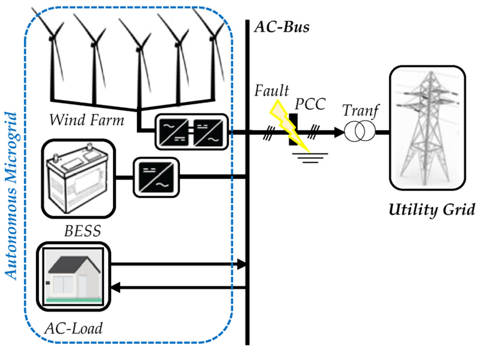
2. Mathematical Modeling of the Microgrid

The suggested grid-connected MG is depicted in Figure 1. The WF and BESS are connected to the AC-bus. The WF consists of five PMSG-WTs; each PMSG-WT is composed of two back-to-back converters coupled with a DC capacitor. Due to its simplicity, robustness, and ease of control, the DT-FLC is added to adjust the wind turbine blade pitch angle during difficult wind conditions and depressed voltage and frequency circumstances.

2.1. Wind Turbine-Mathematical Modeling

Mechanical power generation is described using WT properties. To determine and control the WT-tip-speed ratio (λ) to a specified level, based on WE production and UG conditions, the ARS of the WT (ωr), rotor blade radius (R), and wind speed (vw), are used as indicated in (1):
λ = R ω r v w
By regulating the ARS, the WT is able to generate an optimal mechanical power, Pm, as given in [13,14]:
P m = 1 2 . ρ . π . R 2 . C p ( λ , β ) . v w 3
Consequently, the mechanical Torque, Tm, can be calculated as follows:
T m = P m ω r = 1 2 λ . ρ . π . R 3 . C p ( λ , β ) . v w 2
where ρ is the density of the air, β is the WT-pitch angle, and Cp is the WT-coefficient of power.
There is a specific rotating speed for each instantaneous PMSG-WT wind speed, which corresponds to the maximum wind power. From this maximum wind power, at both high and low ARSs, the DT can be performed. However, the MPPT technique is used only to attain the maximum power point from the WT system [3], when Cpmax = 0.41, λ = 8.1, and β = 0°. As shown in Figure 2, to obtain the most power reserve from the rotor inertia, the suggested technique uses a lower rotor speed. The rotational speeds, ωr and ωr-del, for each given wind speed are equivalent to the maximum and de-loaded output power, Pm and Pd, respectively.

2.2. Permanent Magnet Synchronous Generator-Side Converter Model

The PMSG-SC, as illustrated in Figure 3, is capable of tracking the de-loaded and maximum wind power by adjusting the pitch angle. A rectifier (AC/DC converter) is a power converter in the PMSG-SC that indirectly regulates the ARS. Pulse width modulation (PWM) is added to control the rectifier and inverter and to generate the control signal to execute the generator’s nonlinear regulation [14,15]. According to [16,17,18] the stator dq-axis voltages and PMSG-torques are presented in (4) and (5), respectively:
{ v d s = R s . i d s + L s d i d s d t ω s . L s . i q s ; v q s = R s . i q s + L s d i q g d t ω s . L s . i q s + ω s . ψ f ;
{ T e = 3 2 p . ψ f . i q s ; T m = J d ω r d t + T e
where the stator dq-axis voltages are represented by vds and vqs, ids and iqs represent the PMSG stator currents, the stator inductance and resistance are Ls and Rs, respectively, ωs represents the electrical rotor speed, ψf is the electrical rotor-flux, p is the pole pairs of the generator, J is the rotor inertia, and Te is the electromagnetic torque.

2.3. DC-Link Voltage-Mathematical Modeling

DC-link voltage regulation is critical for the power conversion system, and it is particularly important during a low-voltage situation [5]. Based on the voltage of the DC-link, the supplied power is represented in (6):
P c = C . U d c . d U d c d t = P g P g r i d
where C represents the DC-link capacitor, Pg is the generated power, and Pgrid is the GS-Converter power.

2.4. Grid-Side and Battery Energy Storage System-Mathematical Modeling

As indicated in Figure 3, from the inverter (DC/AC converter), the produced power is injected into the UG. According to [18], the overall GSC model can be defined as follows:
{ v d g = v . i d g R . i d g L d i d g d t + ω s . L . i q g v q g = v . i q g R . i q g L d i q g d t + ω s . L . i d g
where the dq-axis grid-side voltages are vdg and vqg, L is the inductance of the grid, R is the resistance of the grid, and idg and iqg are the grid-side currents on the dq-axis.
The quadrature current iqg and the direct current idg can be used to adjust the reactive and active powers transmitted to the UG, respectively. The active and reactive grid powers are, respectively, given as:
{ P g = 3 2 ( v d g i d g + v q g i q g ) Q g = 3 2 ( v q g i d g v d g i q g )
According to [19], BESS energy storage, which is defined by initial capacity and charging/discharging power, is depicted in (9):
P B E S S t = E B E S S t E B E S S t 1 ( 1 σ ) η . Δ t
where E B E S S t indicates the energy of the battery at time t, σ indicates self-discharge ratio, P B E S S t indicates the charging/discharging power at time t, η indicates battery-efficiency, and Δt indicates the interval of time.
The charging and discharging power of the BESS are restricted to its maximum output power. When charging, the BESS operates as a load, and when discharging, it operates as a generator. Furthermore, it is presumed that when the BESS is charging, its power is negative and that it is positive when it is discharging [20]. This limitation is presented as follows:
P B E S S min P B E S S ( t ) P B E S S max

3. The Proposed De-Loaded-Fuzzy Logic Control

3.1. De-Loaded-LVRT Technique

To enhance MG-LVRT capability and overcome the grid fault, a DT-FLC is proposed. The DT operates with a lower ARS than the MPPT mode. Taking into consideration this maximum speed constraint, the de-loaded operating strategy improves the rotor inertia reserve energy. FLC is added to enhance the DT by smoothing out the wind speed variations effect, controlling, and stabilizing the PMSG side and grid side of each WT as shown in Figure 3.
According to [13,21], for each ARS, the reference of the de-loaded WTG-power, Pref, is calculated as indicated in (11):
P r e f = P d + P r e s × [ ω r d e l ω r m e a s u r e d ω r d e l ω r M P P T ]
with P r e s = P M P P T P d e l ,where Pres is the reserved power, ωr-MPPT, ωr-del, and ωr-measured are the MPPT, de-loaded, and measured rotor speed, respectively.
The voltage-sag duration is required by the grid code. The voltage difference between the normal and the lower grid voltage caused by a fault at PCC, Usag, is calculated as follows:
U s a g = U n U f a u l t
where the voltage drop on the grid is denoted by Usag, the nominal voltage is denoted by Un, and Ufault represents the voltage at the grid fault.
To calculate the reserve energy capacity of the rotor inertia, E r e s W T , the following equation is used:
E r e s W T = 1 2 J ( ω r , max 2 ω r , d e l 2 )
When the power output of the PMSG-SC is dropped, E r e s W T can be stored as kinetic energy in the inertia form. As a consequence, the proposed approach offers a sufficient energy-margin reserve to allow tend power to overcome the grid fault. Therefore, the energy extracted from the ARS for de-loaded operational mode, E r e s W T , can be calculated as follows:
E m e c h W T E B E S S = E r e s W T
with, E B E S S = Q . V , where EBESS represents the energy of the battery (Wh), when a grid fault occurs, this stands for charging to reserve energy depending on the SoC value. Q is the stored quantity of the electricity (Ah), and V is the voltage of the battery. As a result, from (13) and (14), the de-loaded ARS can be determined as follows:
ω r , d e l = ω r , max 2 2 ( E m e c h W T Q V ) J

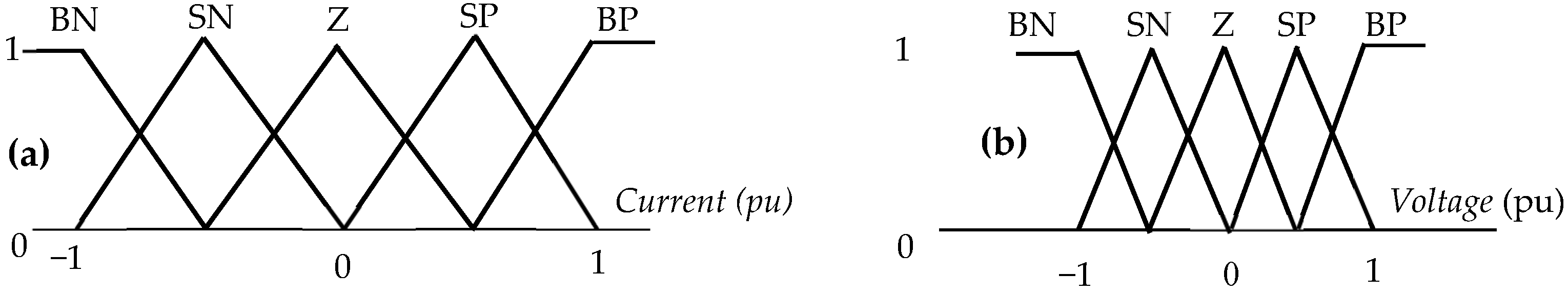
3.2. Fuzzy-Logic Controller Design

The FLC is used in this work to improve the de-loaded technique as shown in Figure 3. The recommended FLC membership function input and output are presented in Figure 4. The FLC position is described in Table 1, and each variable used in the regulator description is presented in a fuzzy set notation utilizing linguistic variables. The input is the current (i), and voltage (u) is the output. On the other hand, the Gaussian function describes the membership functions as big positive (BP), small positive (SP), zero (Z), small negative (SN), and big negative (BN). Figure 5 depicts the suggested FLC design.

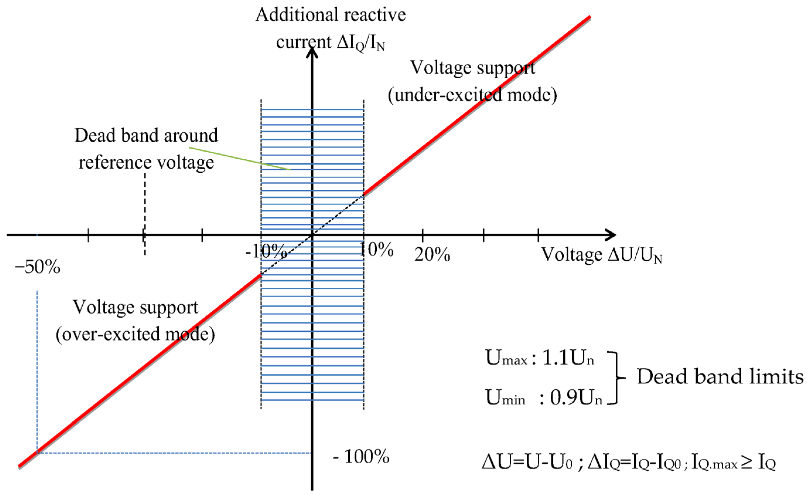
4. Grid Code and Low-Voltage Ride-Through Requirements

4.1. Grid Code Requirement and Fault Ride-Through

In Figure 6, the grid codes of two countries, Morocco and Germany, are shown. The red line represents the grid code of Germany (GCG), and the blue line represents the grid code of Morocco (GCM). For the GCG, the voltage drop is described as 0% of the nominal voltage (0% Un) for 150 ms, with an increase in voltage up to 90% Un at 1500 ms following the fault incident. When the voltage of the grid dips below 90% Un, the LVRT function should be activated. Moreover, according to the GCM, the WT must resist the low voltage up to 80% Un for 600 ms [22,23].
When the grid voltage is oriented on the d-axis (vqg = 0), the active and reactive electricity supplied into the grid may be adjusted by utilizing the quadrature and the direct component currents from (8), resulting in (16):
{ P g = 3 2 . v d g . i d g Q g = 3 2 . v d g . i q g

4.2. Low-Voltage Ride-Through Capability

The wind energy conversion systems (WECSs) should deliver the reactive current to manage the grid voltage if it exceeds 10% of the nominal value on each side of the nominal voltage (Figure 7). The WT must supply a certain amount of reactive current depending on the voltage level. According to (17), the reactive current must be increased after the dead band [23,24] using the following Equation:
I Q I Q 0 2 U U 0 U n I n
where Iq denotes the reactive current, Iq0 denotes the reactive current preceding the fault, In denotes the rated current, U denotes voltage during the fault, U0 denotes the voltage before the fault, and Un denotes the rated voltage.
Grid codes differ by country, but they all have several requirements in common, such as LVRT capabilities, frequency and voltage fluctuation constraints, active and reactive power regulation, and power factor control. According to Figure 7, during a voltage dip, the generating plants must provide more reactive current to the grid. Voltage regulation, as indicated in Figure 7, must be implemented in the case of a voltage sag of more than 10% of the generator voltage effective value. The voltage regulation must be triggered within 20ms after fault detection by supplying a reactive current on the undervoltage side of the machine transformer with a contribution of at least 2% of the rated current per percent of the voltage dip. According to the new GCG, if required, it must be capable of supplying a reactive current of 100% of the rated current [23].
When Ug = 90%Un, to improve the wind energy capture, the de-loaded algorithm will regulate the PMSG-side converter. The active power reference for the grid side is set to the value obtained by the de-loaded algorithm, whereas the reactive power reference is set to zero:
P r e f = P d e l Q r e f = 0

5. Primary Frequency Regulation in an Islanded Microgrid Case

Primary Frequency Regulation

During strong winds and MG disconnection from the grid, the DT-FLC is employed to regulate the pitch angle of the WT-blade and to implement the pitch kinetics controller, as well as the ARS regulation, to adjust the blade pitch angle as indicated in Figure 8. The gradual frequency (Δf) and power (ΔP) variations are linked according to (19):
Δ f = K f . Δ P
where Kf is the frequency droop factor constant, and Δf and ΔP are the frequency deviation and the active power margin, respectively.
The active power margin can be determined in the following way, depending on the condition of the battery charge/discharge:
Δ P = P W F ± P B E S S P L
According to [21], the actual droop factor is calculated as follows:
K f . a c t = K f . max ( K f . max K f . min ) [ P r e s a c t P r e s min P r e s max P r e s min ]
where Pres-act is the WTG actual power margin, Pres-max is the WTG maximum power margin, Pres-min is the minimum power margin, and Kf.max and Kf.min are the maximum and minimum droop (%), respectively.

6. Simulation Results

The simulation findings are shown per unit in both cases, the connected and islanded mode. In this study, the PCC (point common coupling) is in fact the origin of the voltage drops. Table 2 summarizes the results obtained and the advantages and disadvantages of each controller. In Table 3 and Table 4, the PMSG and BESS parameters are listed.

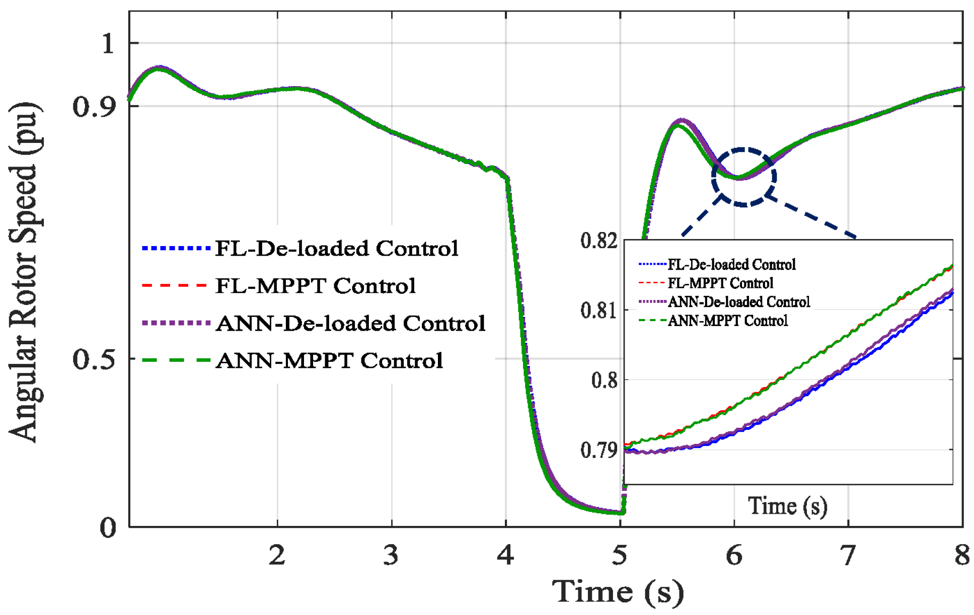
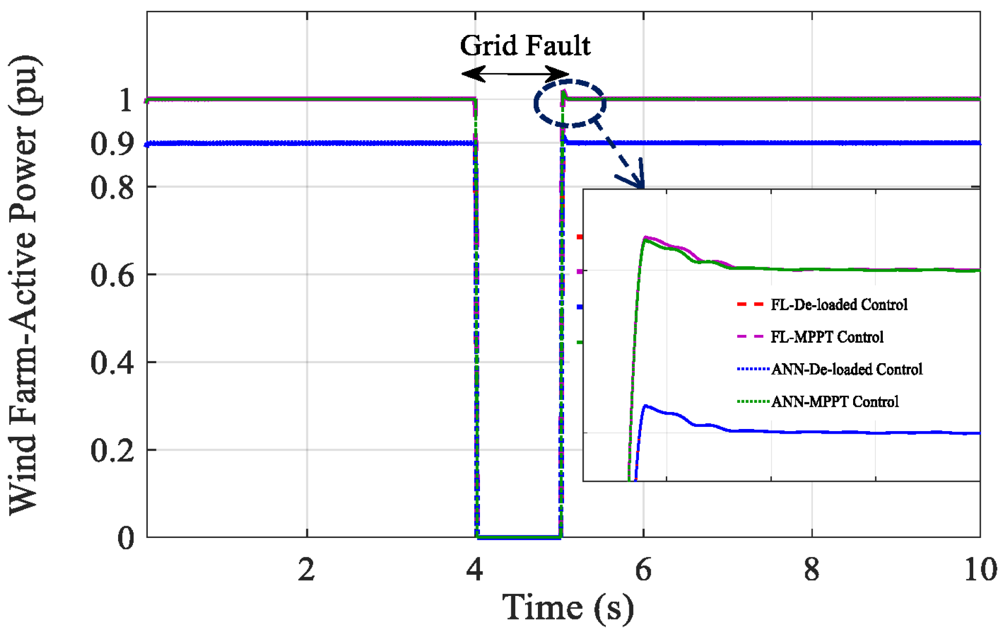
6.1. Case 1: Grid-Connected Microgrid under LVRT Mode

According to the LVRT requirements, the MG must be maintained connected to the UG after the short-circuit problem occurred at the PCC. A grid fault event is investigated at PCC during 1000 ms. To ride through the low-voltage, the DT and FLC are compared with MPPT and ANN. On the other hand, BESS is considered to be used in difficult weather conditions.
In Figure 9, the wind speed is taken at around 0.67 pu and 0.99 pu to illustrate the system performance. Under the grid faults, the response of the DC-link voltage control strategy with FLC in comparison with ANN is shown in Figure 10. The voltage instability caused saturation of current, resulting in a DC-link voltage disturbance. The LVRT is performed as both strategies gave approximately the same answer; that is, the DC link voltage was kept in the range −0.047% and +0.04% from the rated DC-Link voltage in the fault time and remained constant after the fault. As illustrated in Figure 10, in comparison with the ANN technique, the proposed technique (green line) clearly reduces the DC-link voltage fluctuations.
To optimize the WT-power output, the ARS tracked the variation of the wind speed and decreased when the fault occurred. With the DT-FLC, the ARS attitude during the grid fault is depicted in Figure 11. As can be noticed, a reserve is produced through ARS control to supply spinning reserves. Indeed, under severe wind speed variation, the WF supplies electricity to the system by generating and storing the rotor’s kinetic energy more effectively.
Figure 12 shows the PCC voltage drop; with the proposed technique, the fluctuations are lower and the system is more stable. This leads to the mitigation of the power fluctuations and peaks supplied to the MG. Figure 13 and Figure 14 show the restriction in the active power corresponding to an increase in reactive power. During a grid fault, GSC power is zero in both techniques. However, taking into account the rotor speed restriction, the proposed solution dropped its power by 10% less than the MPPT value. The reactive power injected by the microgrid to the grid during the voltage sag started at t = 4 s. With the DT-FLC, the power and voltage were stable in comparison with MPPT (green and purple lines). The injected reactive power by the WF during the fault restores the PCC voltage, and its value changes from 0 to 0.9 pu and from 0 to 1 pu for de-loaded and MPPT techniques, respectively, to fulfill the LVRT requirements given by GCG.
Figure 15 illustrates battery SoC with both techniques, the DT-FLC and MPPT-FLC. With the DT-FLC, the battery responds faster, at only 0.02 s, after the start of the voltage sag. However, with MPPT-FLC, the battery responses at 0.13 s after the fault. Due to the FLC performance, both techniques, MPPT and the DT, maintain the SoC between 0.25 and 0.85 pu to protect and prolong the battery life span. Hence, the battery participates adequately in the LVRT requirement and contributes to enhancing the reliability and stability of the MG.

6.2. Case 2: Islanded Microgrid Mode

If the issue continues to take longer than the grid code allows, the MG must disconnect from the UG to preserve its stability and load supply. In this mode, the MG is 100% renewable, and WTGs and batteries are used to meet the load demand. Figure 16 depicts the fluctuation in load demand (blue line), the output de-loaded, and maximum WF powers (green and red lines, respectively). The load demand suddenly decreases from 1 to 0.95 pu at 3 s and increases from 0.95 to 0.9736 pu at 6 s to be stabilized in this value. At the same time, with 10% of power reserve between the two output WF powers, the de-loaded and MPPT power follow the wind speed variations previously shown in Figure 10. The wind power regulation is faster due to the pitch angle control of the proposed technique. The power is reserved by storing more kinetic energy as shown in Figure 16. The droop between the two powers is used to overcome the frequency fluctuations. Figure 17 shows the battery participation in the primary frequency regulation using de-loaded control enhanced by FLC. Battery power varies between −0.0264 and 0.64 pu, as a minimum and maximum value, respectively.
The disconnection of the load from the grid caused unexpected demand from the islanded microgrid, which creates a frequency variation as seen in Figure 18. As indicated in the same figure and in Table 2, during high load, with the DT-FLC (blue line), the frequency dips are reduced (−0.0007 Hz), which results in preventing MG loss and distortion during load increase or disconnection from the grid. However, with FLC-MPPT (red line), ANN-de-loaded (green line), and ANN-MPPT (purple line), the frequency deviation is −0.0038 Hz, −0.02 Hz, and −0.022 Hz, respectively. The disturbing frequency under the power variation is regulated following the load connection. With the DT-FLC, the autonomous-MG participates in PFR better than the other controllers. This variation is within the IEEE standard (IEEE Std 1547–2018) and Moroccan grid code which recommend a limited frequency default droop at (−3 Hz) and (−2.5 Hz), respectively, [25,26]. However, without control (orange line), the system is unstable after the disconnection from the grid, causing severe frequency deviation.

7. Conclusions

In this paper, a new control strategy is investigated for connected-MG and islanded-MG based on the DT-FLC. The studied MG is more resilient during and after a fault due to the ARS control by absorbing kinetic energy from the rotor. The findings show that an MG using the suggested approach is much better at responding to the LVRT requirement (connected mode) and PFR (islanded mode) when compared to the MPPT and ANN control. Furthermore, the BESS operation is explored to enhance the suggested control. When faults occur, BESS support is employed to preserve stability and mitigate the negative effects of grid integration. In addition, the PWM-based-FLC is suggested to govern the PMSG-side converter. Finally, from the obtained results in both cases, the proposed technique has shown the system stability and robustness and has successfully maintained the system voltage and frequency within a standard operating band that is defined by the grid codes.

Author Contributions

Conceptualization, A.M. and M.O.; methodology, A.M. and M.O.; software, A.M.; validation, A.M., M.O., S.H.L. and Z.C.; formal analysis, A.M. and Z.C.; investigation, S.H.L. and Z.C.; resources, M.O., Z.C. and S.H.L.; data curation, A.M. and Z.C.; writing—original draft preparation, A.M. and M.O.; writing—review and editing, A.M., M.O., Z.C. and S.H.L.; visualization, Z.C. and M.O.; supervision, M.O.; project administration, M.O; funding acquisition S.H.L. All authors have read and agreed to the published version of the manuscript.

Funding

This work was supported in part by “Regional Innovation Strategy (RIS)” through the National Research Foundation of Korea (NRF) funded by the Ministry of Education (MOE) (No. 1345356235) and in part by the Korea Institute of Energy Technology Evaluation and Planning (KETEP) grant funded by the Korean government (MOTIE) (20223A10100030, Development of Synchronous Condenser Model and Power System Inertia Operating Technology).

Conflicts of Interest

The authors declare no conflict of interest.

References

  1. Barra, P.H.A.; de Carvalho, W.C.; Menezes, T.S.; Fernandes, R.A.S.; Coury, D.V. A review on wind power smoothing using high-power energy storage systems. Renew. Sustain. Energy Rev. 2021, 137, 110455. [Google Scholar] [CrossRef]
  2. Kiehbadroudinezhad, M.; Merabet, A.; Abo-Khalil, A.G.; Salameh, T.; Ghenai, C. Intelligent and optimized microgrids for future supply power from renewable energy resources: A review. Energies 2022, 15, 3359. [Google Scholar] [CrossRef]
  3. Djilali, L.; Sanchez, E.N.; Ornelas-Tellez, F.; Avalos, A.; Belkheiri, M. Improving microgrid low-voltage ride-through capacity using neural control. IEEE Syst. J. 2019, 14, 2825–2836. [Google Scholar] [CrossRef]
  4. de Carvalho, W.C.; Bataglioli, R.P.; Fernandes, R.A.; Coury, D.V. Fuzzy-based approach for power smoothing of a full-converter wind turbine generator using a supercapacitor energy storage. Electr. Power Syst. Res. 2020, 184, 106287. [Google Scholar] [CrossRef]
  5. Kim, C.; Kim, W. Low-voltage ride-through coordinated control for PMSG wind turbines using de-loaded operation. IEEE Access 2021, 9, 66599–66606. [Google Scholar] [CrossRef]
  6. Kharrich, M.; Kamel, S.; Abdeen, M.; Mohammed, O.H.; Akherraz, M.; Khurshaid, T.; Rhee, S.-B. Developed approach based on equilibrium optimizer for optimal design of hybrid PV/wind/diesel/battery microgrid in Dakhla, Morocco. IEEE Access 2021, 9, 13655–13670. [Google Scholar] [CrossRef]
  7. Hossain, A.; Chakrabortty, R.K.; Ryan, M.J.; Pota, H.R. Energy management of community energy storage in grid-connected microgrid under uncertain real-time prices. Sustain. Cities Soc. 2021, 66, 102658. [Google Scholar] [CrossRef]
  8. Roy, S.D.; Debbarma, S. Inertia emulation using battery management system in a low inertia grid with HVDC links. In Proceedings of the 2nd International Conference on Power, Energy and Environment: Towards Smart Technology (ICEPE), Shillong, India, 1–2 June 2018; pp. 1–9. [Google Scholar]
  9. Kotb, K.M.; Elmorshedy, M.F.; Salama, H.S.; Dán, A. Enriching the stability of solar/wind DC microgrids using battery and superconducting magnetic energy storage based fuzzy logic control. J. Energy Storage 2022, 45, 103751. [Google Scholar] [CrossRef]
  10. Roslan, M.; Hannan, M.; Ker, P.J.; Uddin, M. Microgrid control methods toward achieving sustainable energy management. Appl. Energy 2019, 240, 583–607. [Google Scholar] [CrossRef]
  11. Salyani, P.; Zare, K.; Abapour, M.; Safari, A.; Shafie-Khah, M. A general mathematical model for LVRT capability assessment of DER-penetrated distribution networks. IEEE Access 2020, 8, 125521–125533. [Google Scholar] [CrossRef]
  12. Yan, W.; Wang, X.; Gao, W.; Gevorgian, V. Electro-mechanical modeling of wind turbine and energy storage systems with enhanced inertial response. J. Mod. Power Syst. Clean Energy 2020, 8, 820–830. [Google Scholar] [CrossRef]
  13. Mahrouch, A.; Ouassaid, M. Primary frequency regulation based on deloaded control, ANN, and 3D-fuzzy logic controller for hybrid autonomous microgrid. Technol. Econ. Smart Grids Sustain. Energy 2022, 7, 1. [Google Scholar] [CrossRef]
  14. Errami, Y.; Maaroufi, M.; Cherkaoui, M.; Ouassaid, M. Maximum power point tracking strategy and direct torque control of permanent magnet synchronous generator wind farm. In Proceedings of the 2012 IEEE International Conference on Complex Systems (ICCS), Agadir, Morocco, 5–6 November 2012. [Google Scholar]
  15. Errami, Y.; Ouassaid, M.; Maaroufi, M. Modeling and variable structure power control of PMSG based variable speed wind energy conversion system. J. Optoelectron. Adv. Mater. 2013, 15, 1248–1255. [Google Scholar]
  16. Errami, Y.; Ouassaid, M.; Maaroufi, M. A performance comparison of a nonlinear and a linear control for grid connected PMSG wind energy conversion system. Int. J. Electr. Power Energy Syst. 2015, 68, 180–194. [Google Scholar] [CrossRef]
  17. Chatri, C.; Ouassaid, M.; Labbadi, M.; Errami, Y. Integral-type terminal sliding mode control approach for wind energy conversion system with uncertainties. Comput. Electr. Eng. 2022, 99, 107775. [Google Scholar] [CrossRef]
  18. Wang, J.; Ben, Y.; Zhang, J.; Feng, H. Low voltage ride-through control strategy for a wind turbine with permanent magnet synchronous generator based on operating simultaneously of rotor energy storage and a discharging resistance. Energy Rep. 2022, 8, 5861–5870. [Google Scholar] [CrossRef]
  19. Liu, Z.; Zhang, Z.; Zhuo, R.; Wang, X. Optimal operation of independent regional power grid with multiple wind-solar-hydro-battery power. Appl. Energy 2019, 235, 1541–1550. [Google Scholar] [CrossRef]
  20. Salman, U.T.; Al-Ismail, F.S.; Khalid, M. Optimal sizing of battery energy storage for grid-connected and isolated wind-penetrated microgrid. IEEE Access 2020, 8, 91129–91138. [Google Scholar] [CrossRef]
  21. Boyle, J.; Littler, T.; Muyeen, S.M.; Foley, A.M. An alternative frequency-droop scheme for wind turbines that provide primary frequency regulation via rotor speed control. Int. J. Electr. Power Energy Syst. 2021, 133, 107219. [Google Scholar] [CrossRef]
  22. Ismail, D.; Fadili, A.E.; Kasmi, D.E.; Stitou, M. Evaluation of the LVRT requirement for wind farms specified in the Moroccan grid code. In Proceedings of the 2018 Renewable Energies, Power Systems & Green Inclusive Economy (REPS-GIE), Casablanca, Morocco, 23–24 April 2018. [Google Scholar]
  23. E.ON Netz GmbH. Netzanschlussregeln für Hoch- und Höchstspannung. 2006. Available online: https://www.n-ergie-netz.de/public/remotemedien/media/mdn/infothek_1/veroeffentlichungen/weitere_veroeffentlichungen/pflichtveroeffentlichungen/kraftnav/NetzanschlussregelnEON1.pdf (accessed on 24 October 2022).
  24. Gao, D.W.; Wu, Z.; Yan, W.; Zhang, H.; Yan, S.; Wang, X. Comprehensive frequency regulation scheme for permanent magnet synchronous generator-based wind turbine generation system. IET Renew. Power Gener. 2019, 13, 234–244. [Google Scholar] [CrossRef]
  25. IEEE Std 1547-2018; IEEE Standard for Interconnection and Interoperability of Distributed Energy Resources with Associated Electric Power Systems Interfaces. IEEE: Picastaway, NJ, USA, 2018.
  26. Aboubakrc, M.E. Amélioration de L’intégration de L’énergie Eolienne au Réseau Electrique de Transport Marocain. Ph.D. Thesis, Centre d’Etudes Doctorales, Sciences et Techniques de l’Ingénieur Faculté des Sciences et Techniques–Fès, Fès, Morocco, 2018. Available online: https://toubkal.imist.ma/bitstream/handle/123456789/11750/THESE_MAKRINI.pdf?sequence=1 (accessed on 24 October 2022).
Figure 1. The suggested grid-connected MG architecture.
Energies 16 00291 g001
Figure 2. Wind turbine characteristics with de-loaded and maximum power point tracking.
Energies 16 00291 g002
Figure 3. The global scheme of the wind-farm-based five PMSG configuration [14,15,16].
Energies 16 00291 g003
Figure 4. Membership functions of the input (a) and the output (b) of the proposed fuzzy-logic controller.
Energies 16 00291 g004
Figure 5. The construction of the fuzzy-logic controller.
Energies 16 00291 g005
Figure 6. Fault ride-through requirement voltage profile given by E. ON, Netz and GCM [22,23].
Energies 16 00291 g006
Figure 7. The concept of voltage control during voltage perturbations according to the E. ON grid code [23].
Energies 16 00291 g007
Figure 8. The proposed modeling of de-loaded-technique-based FLC to regulate the pitch angle and the mechanical torque.
Energies 16 00291 g008
Figure 9. Available wind speed alteration.
Energies 16 00291 g009
Figure 10. The DC-link voltage output.
Energies 16 00291 g010
Figure 11. Angular rotor speed at the time of the grid-voltage sag.
Energies 16 00291 g011
Figure 12. The voltage at PCC at the time of the grid-voltage sag.
Energies 16 00291 g012
Figure 13. Grid active power at the time of the grid-voltage sag.
Energies 16 00291 g013
Figure 14. Reactive power at the time of the grid-voltage sag.
Energies 16 00291 g014
Figure 15. BESS participation in LVRT requirements.
Energies 16 00291 g015
Figure 16. Load-demand and WT powers.
Energies 16 00291 g016
Figure 17. Battery power variations using de-loaded control.
Energies 16 00291 g017
Figure 18. DT-FLC and MPPT frequency control variation.
Energies 16 00291 g018
Table 1. Rules for the fuzzy-logic controller.
i\uBNSNZSPBP
BNZSNSNBNBN
SNSPZSNBNBN
ZSPSPZSNSN
SPBPBPSPZSN
BPBPBPSPSPZ
Table 2. Quantitative comparison between FLC and ANN with both techniques.
Primary Frequency Droop (Hz)Voltage Droop (%) and System Stability after the Fault
ControllerFLCANNVoltage DroopSystem Stability
De-loaded technique−0.0007−0.02−70High
MPPT Technique−0.0038−0.022−80Medium
Table 3. PMSG and battery Parameters.
ParametersDescriptionValue
VnNominal Voltage660 V
PActive Power2 MW
UdcDC-Link Voltage1500 V
ωrRated angular rotor speed2.57 rad/s
fRated Frequency50 Hz
CDC-link Capacitor4400 μF
vwNominal Wind Speed12.4 m/s
ρAir density1.225 kg/m3
ASwept Area4775.94 m²
Lq, LdStator d-axis and
q-axis inductance
0.0003 H
RResistance of the Stator0.008 Ω
pPole pairs 60
ψfPermanent magnet flux0.192 Wb
Table 4. Battery parameters.
ParametersDescriptionValue
InRated Battery Current120 A
nbBattery Cell Number10
RiInterne Resistance0.008 Ω
Disclaimer/Publisher’s Note: The statements, opinions and data contained in all publications are solely those of the individual author(s) and contributor(s) and not of MDPI and/or the editor(s). MDPI and/or the editor(s) disclaim responsibility for any injury to people or property resulting from any ideas, methods, instructions or products referred to in the content.

