Article

Design of Stator Winding Turn Number of Tap-Change PMSM for EVs According to Driving Cycles

1
Department of Electrical Engineering, Hanyang University, Seoul 04763, Republic of Korea
2
School of Energy Engineering, Kyungpook National University, Daegu 41566, Republic of Korea
3
POSCO, Pohang 37859, Republic of Korea
*
Author to whom correspondence should be addressed.
Energies 2023, 16(1), 412; https://doi.org/10.3390/en16010412
Submission received: 4 November 2022 / Revised: 7 December 2022 / Accepted: 26 December 2022 / Published: 29 December 2022

Abstract

:
Driving cycles are commonly used to evaluate the fuel efficiency and mileage of internal combustion engine vehicles and electric vehicles (EVs). To improve the mileage of EVs, efficient propulsion motors and inverters must be employed, particularly at frequently used speed and torque points of driving cycles. In this study, the number of the stator winding turns of a tap-change permanent magnet synchronous motor (PMSM) used for EV propulsion was investigated to increase the motor and inverter energy efficiencies under an urban dynamometer driving schedule (UDDS), a highway fuel economy test (HWFET), and combined UDDS/HWFET driving cycles. The motor core loss due to the carrier harmonics, copper loss, and inverter loss were analyzed for various winding turn number combinations, and the most efficient combination was selected. Based on the analysis results, the tap-change motor winding turns that exhibited the least loss were rewound on a PMSM of a mass-produced EV. The demand energy of the proposed tap-change PMSM and that of a mass-produced PMSM in the UDDS, HWFET, and combined UDDS/HWFET driving cycles were compared through experimentation. The proposed PMSM exhibited energy improvements of 1.50%, 1.84%, and 1.65%, respectively.

1. Introduction

The production and use of electric vehicles (EVs) are growing globally because they are eco-friendly and reduce greenhouse gas emissions. The consumer selection criteria for purchasing EVs have diversified and include fuel efficiency, maximum mileage, acceleration performance, price, design, driving convenience, and brand awareness; among these, the first two are the most important factors. Fuel efficiency is the average mileage per unit electric energy of an EV battery, whereas the maximum mileage indicates the distance that can be driven under a maximum charge state. A higher fuel efficiency allows the same mileage with a lower battery capacity; consequently, it enhances the competitiveness of the vehicle by reducing the price and curb weight.
To measure the fuel efficiency and maximum mileage under the same conditions, a test drive profile is set and they are measured via a simulation test using a dynamometer. This test drive profile is referred to as a driving cycle. Various driving cycles exist because these are specified by considering geographical characteristics and vehicle type [1,2,3,4]. In the United States, urban and highway driving profiles have been established and used by the US Environmental Protection Agency (EPA) as urban dynamometer driving schedule (UDDS) and highway fuel economy test (HWFET) driving cycles [4]. Figure 1a,b demonstrate the UDDS and HWFET driving cycles, respectively. The UDDS and HWFET driving cycles have average speeds of 19.59 mph (31.5 km/h) and 48.3 mph (77.7 km/h), respectively. In addition, vehicle acceleration and deceleration behavior, and the number of times a vehicle stops and moves vary, as they characterize urban and highway driving conditions [4].
The design of typical motor focuses on a few operating points, including the maximum continuous or overload output torque and power. However, to measure the fuel efficiency and maximum mileage, EV motors operate over the driving cycle, which differs at rated or overload conditions. Studies have focused on designing a high-efficiency motor based on high-frequency operating points in such driving cycles [5,6,7,8,9]. Optimization of a permanent-magnet-assisted synchronous reluctance motor was performed to reduce copper and iron losses according to the UDDS and US06 supplemental federal test procedure (US06/SFTP) [5]. A switched reluctance motor was optimized with new European driving cycles (NEDC) [6] where the output torque, motor loss, and torque ripple were considered for design optimization with the Taguchi method. The permanent magnet synchronous motor (PMSM) design was also optimized in [7]; a multi-objective generic method was used with the NEDC and UDDS to reduce the core loss and torque ripple, while the output torque was increased. A flux mapping optimization strategy suitable for light vehicle driving cycles was employed by changing the stator and rotor structures of a permanent magnet motor [8]. A finite element method (FEM) and temperature network model were used for the optimization of a permanent magnet motor for a four-wheel-drive EV [9]. However, achieving optimized motor parameters while satisfying both UDDS and HWFET driving cycles is challenging owing to their differing characteristics based on urban and highway drive conditions. Furthermore, although these previous studies focused on the reduction in motor loss, they did not analyze the drive circuit and the effect of motor design on harmonics losses.
Because the UDDS and HWFET driving cycles have different average vehicle speed, the frequent operating speed of EV motors is different. To obtain a higher energy efficiency with both cycles, a winding changeover motor can be used because it changes the winding configuration or number of stator windings according to the speed and torque operating points. There are three types of winding changeover methods: (a) Wye-delta switching [10,11,12,13,14]; (b) Series-parallel winding reconnection [10,15]; (c) Tap-change method [16,17,18]. Conventional winding changeover methods include wye-delta switching or series-parallel winding reconnection with a fixed 3 : 1 or 2:1 turn ratio [10]. Wye-delta switching has been widely used with AC induction motors, using various switches from wye to delta configurations or vice versa [11,12,13,14]. Wye-delta switching with mechanical contactors [11,12], as well as a method for simultaneously changing the wye-delta connection and the number of turns [13] have been proposed. These methods suffer from problems in the zero-stator current duration for a safe transition. Shi et al. [14] replaced the mechanical contactors with silicon-controlled rectifiers; however, surge currents existed during transition. Shin et al. [15] demonstrated that series-parallel winding reconnections with thyristors can exhibit high efficiencies at high speeds by reducing copper losses. However, high surge currents were observed during the transition periods.
Wye-delta switching and series-parallel winding reconnection have a fixed turn ratio; however, the tap-change method comprises winding change circuits that specify the number of windings using additional switches and a motor that involves winding taps for changing the number of windings [16,17,18,19]. A magnetic contactor was used in [16]. During the tap-changing transition, the phase current should be reduced to zero to avoid spark voltage at the contactor; however, the zero-stator current invokes the zero-output torque period. To overcome this constraint, the current path must be secured during the tap-changing transition. Otherwise, a spark voltage may occur. Moreover, if the switching time increases, the airgap flux changes and the torque ripple increases. To address these issues, winding change methods involving tap-change circuits have been studied [17,18,19]. Silicon-controlled rectifiers with a snubber circuit were proposed in [17]. An EV drive system with the tap-changing method proposed in [17] was implemented, and its high efficiency was validated by selecting the number of tap-change motor windings in [18]. A snubberless solid-state tap-changing method was investigated in a recent study [19], which minimized the torque ripple and reduced the tap-changing time to a few microseconds [19]. The tap-changing method is used in this study.
Figure 2 shows the tap-change motor configurations, where V d c is the DC-link voltage [19]. The stator windings shown in Figure 2 are divided into primary and secondary on the left and right sides, respectively, where N 1 and N 2 indicate the winding turn numbers per slot. T S 1 and T S 2 are the tap-changer switches; during a conventional operation without tap-changing, only one set of switches is active. When T S 1 is active, the current flows through a primary winding, and the turn number N 1 is used for the operation, as shown in Figure 2a. When T S 2 is active, the current flows through primary and secondary windings ( N 1 + N 2 ), as shown in Figure 2b. The conventional selection of the number of tap-change motor windings aims to increase the number of winding turns resulting in a decrease in the speed, such that a high torque is obtained with a low phase current [20]. However, when the number of stator winding turns is lowered, the phase current can be reduced in the high-speed region by reducing the field-weakening (FW) current. Therefore, when only primary winding is used, it is referred to as the high-speed mode; when both primary and secondary windings are used, it is referred to as the low-speed mode [19].
In this study, the winding turn numbers of EV tap-change motors were investigated to obtain the maximum fuel efficiency and mileage based on UDDS, HWFET, and combined UDDS/HWFET driving cycles. The remainder of this paper is organized as follows. Section 2 presents the primary reason for using a tap-change motor as the EV propulsion motor. Section 3 presents the core loss model due to the high carrier harmonics, copper loss, and inverter loss. The motor and inverter losses are analyzed for various winding turn number combinations of N 1 and N 2 , and the most efficient combination is derived in Section 4. Using the derived turn numbers, a 150 kW mass-produced reference EV motor was rewound to implement the tap-change motor, and the efficiency improvement was measured through testing at the operating points of the UDDS, HWFET, and combined UDDS/HWFET driving cycles presented in Section 5. The experimental results indicate that the proposed tap-change motor exhibits less energy demand than the mass-produced reference motor during the driving cycles.

2. Loss Reduction at Significant Operating Points of the Driving Cycle

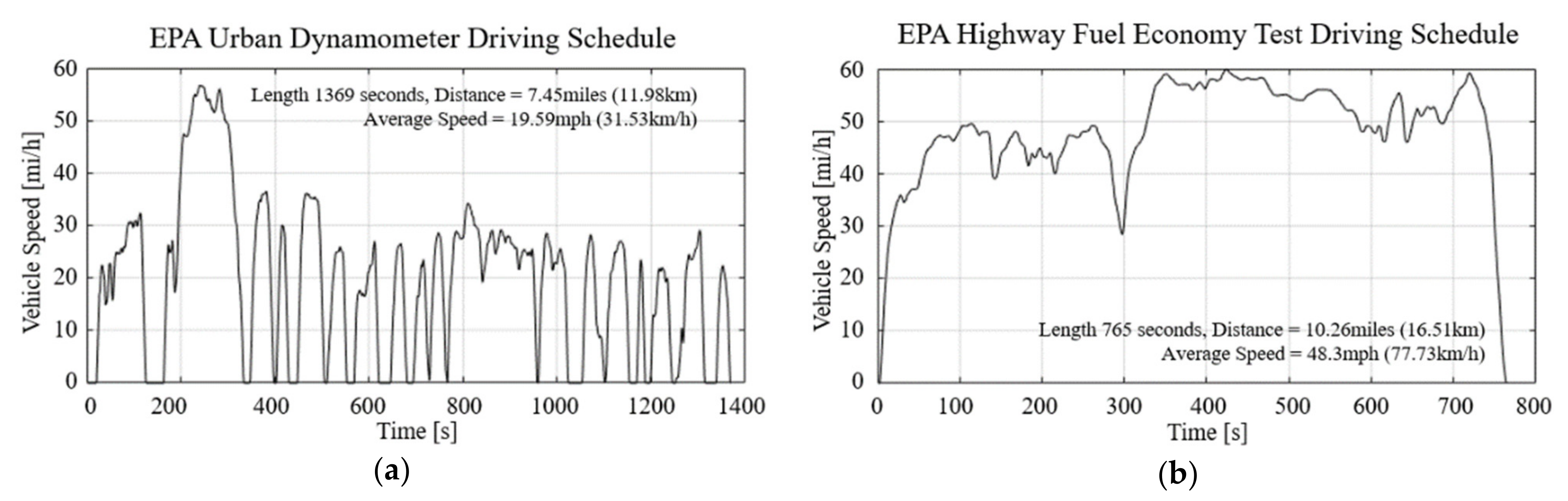
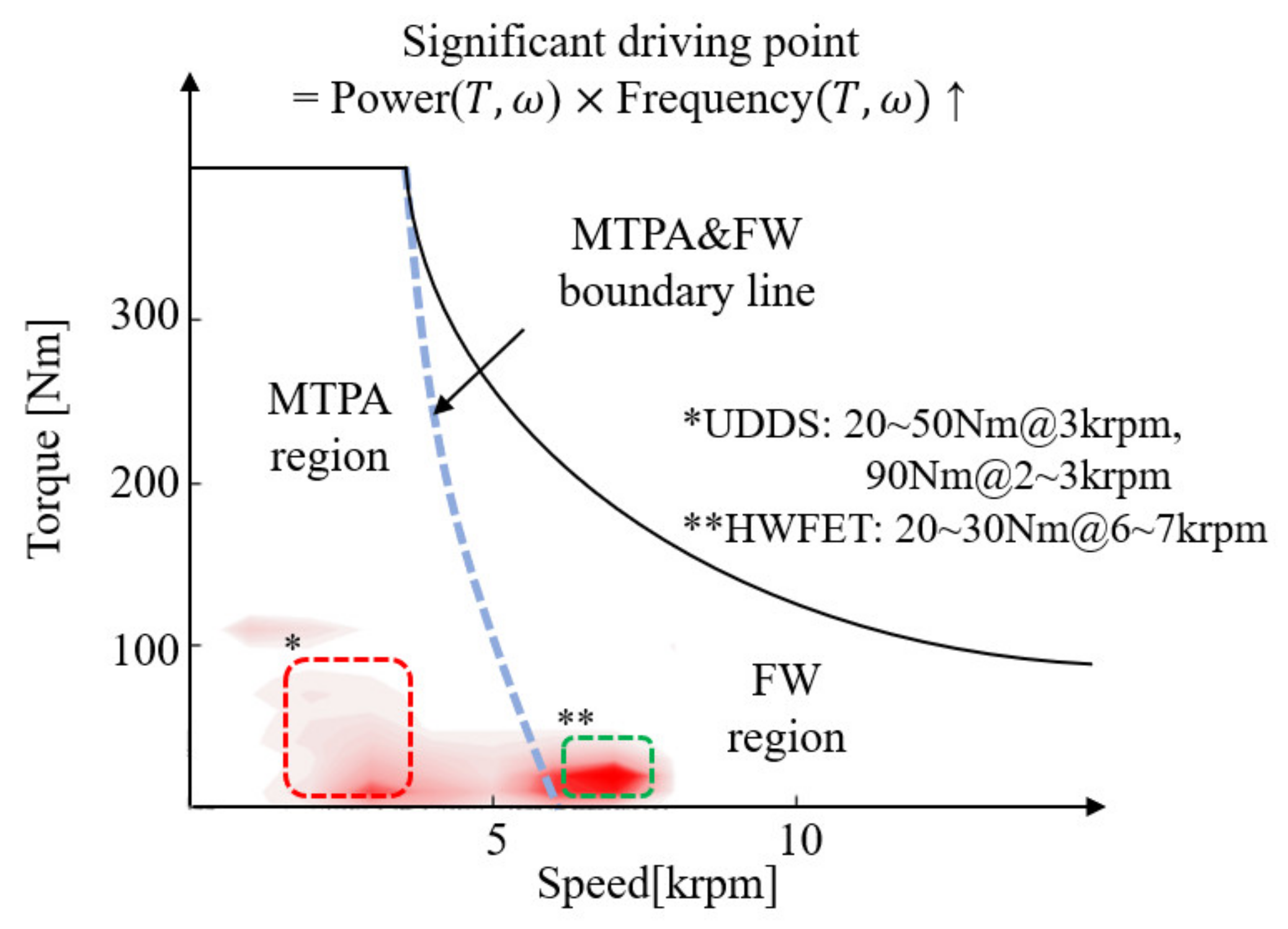
2.1. Driving Cycles in Motor Torque Speed Plane

Figure 3 shows the relative significance of each driving point on the speed and torque plane when the EVs are simulated with a combined driving cycle (55% UDDS and 45% HWFET). The significance of the driving point is obtained by multiplying the speed-torque frequency with the motor output power at each operating point. The regions with a high number of significant driving points are shown in red; a lighter shade of red indicates lower significance. The significance of each driving point is expressed as the product of the speed-torque frequency and the motor output power, both of which directly affect the energy consumed by the vehicle with these driving cycles. The solid line shown in Figure 3 is the maximum operating region of the motor, and the dotted line is the boundary between the maximum torque per ampere (MTPA) region and the FW region. The region on the left side is MTPA, which utilizes the control method that outputs the maximum torque with the minimum current [21]. The MTPA enables a high-efficiency drive in the range below the rated speed. However, when the rotor speed exceeds the rated speed, FW is essential. The FW control method lowers the air gap flux by injecting a stator current owing to the limitation of the inverter output voltage [22,23]. In contrast to the MTPA method, the FW control method applies a higher current as the speed increases; thus, the efficiency of the inverter and motor decreases.
The driving points with the highest weight in the combined driving cycle were 20–50 Nm (3 krpm), 90 Nm (2 and 3 krpm), and 20–30 Nm (6~7 krpm), as shown in Figure 3. A speed in the range of 2–3 krpm is the primary driving point of UDDS, indicating urban operation with repeated acceleration and deceleration at low speeds. By contrast, a speed in the range of 6–7 krpm is the main operating point of an HWFET, indicating constant speed on a highway with a low torque. A low torque rather than a rated torque is mainly used for the operation of an EV. A combined driving cycle has two significant speed zones of 3 and 7 krpm. If the efficiency in these two zones is increased, the fuel efficiency and mileage would improve owing to the energy saved over an entire driving cycle. Thus, a tap-change motor was designed in this study, which focused on these two speed regions to improve the overall energy efficiency.

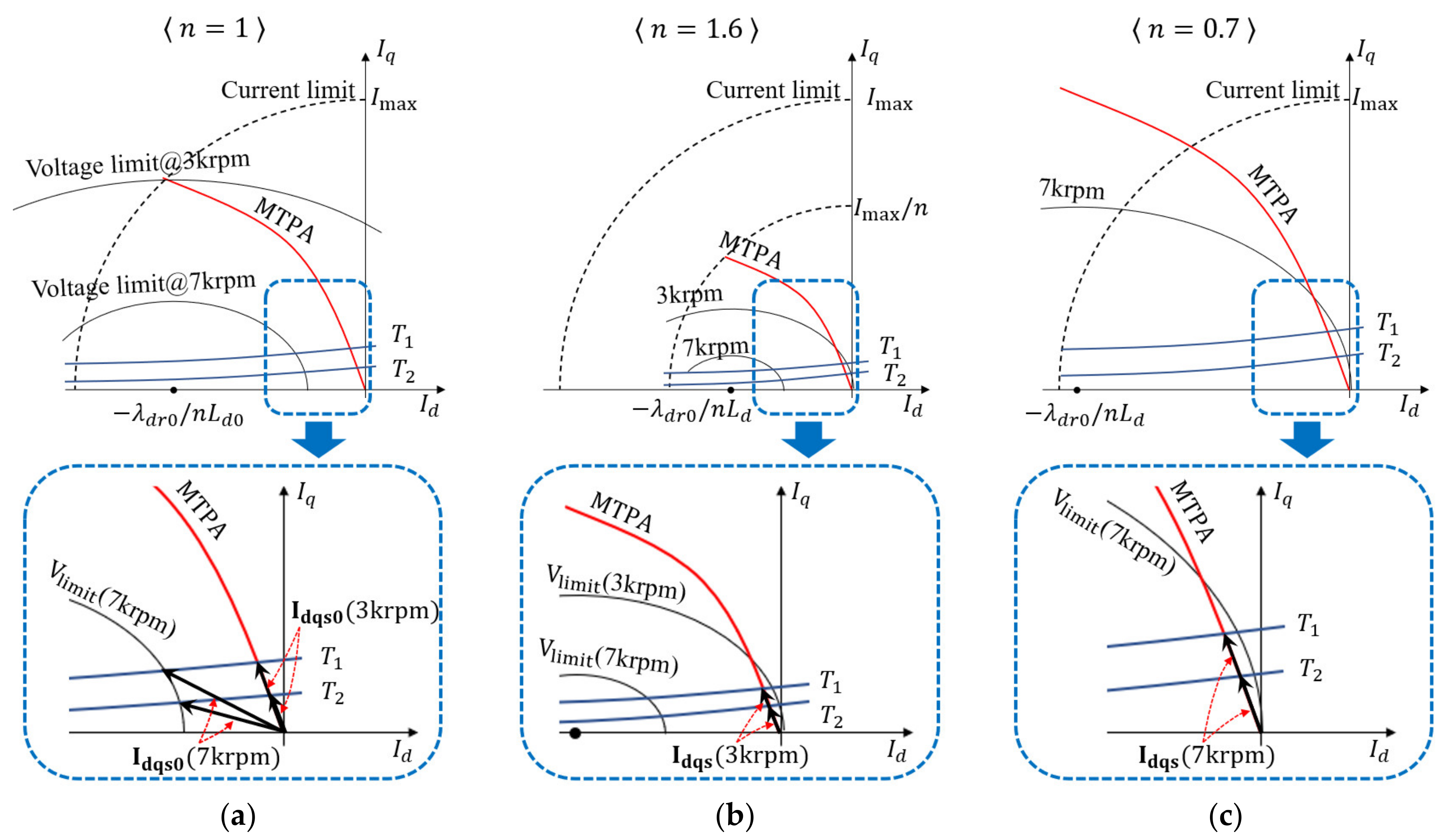
2.2. Variation of Motor Current, Voltage, and Motor Parameters According to the Stator Winding Turn Ratio

In this study, a mass-produced EV PMSM is used as a reference motor. The tap-change motor is implemented by modifying only the stator winding turn numbers from this reference motor without any physical change and they are compared based on energy consumption over the driving cycles. Figure 4 shows a cross-sectional view of the motor and conductors in a slot of the reference motor ( N 0   = 10 turns) and tap-change motor ( N 1 = 7 turns and N 2 = 9 turns) where N 0 denotes the winding turn number per slot of the reference motor. The parameters of the reference motor are listed in Table 1. The proposed tap-change motor is implemented by removing the N 0 windings of the reference motor stator and rewinding the N 1 and N 2 windings. Therefore, the characteristics of the reference motor are maintained in the tap-change motor.
Using the same slot fill factor as that of the reference motor, the primary and secondary winding resistances of the tap-change motor, R s N 1   and R s N 2   , are expressed by (1) and (2) as follows:
R s N 1   = R s 0 N 1 N 1 + N 2 N 0 2
R s N 2   = R s 0 N 2 N 1 + N 2 N 0 2
where R s 0 denotes the phase resistance of the reference motor. The parameters of the tap-change motor can be expressed in terms of the stator turn ratio n and the parameters of the reference motor. For the tap-change motor, n equals N 1 + N 2 / N 0 and N 1 / N 0 in low- and high-speed modes, respectively. Given n , the d- and q-axis inductances, L d   and L q , and the back electromotive force constant λ d r are obtained as follows:
L d = n 2 L d 0
L q = n 2 L q 0
λ d r = n λ d r 0
where L d 0 , L q 0   and λ d r 0 denote the d- and q-axis inductances and the back electromotive force constant of the reference motor, respectively. Subsequently, using (3)–(5) and ignoring the ohmic drop, the voltage and torque equations are derived using the inductance and back electromotive force constant of the reference motor in the steady state as follows:
v d s = ω e n 2 L q 0 i q s                                                                                                      
v q s = ω e n 2 L d 0 i d s + ω e n λ d r 0                                                                  
T = 3 2 P 2 n λ d r 0 i q s + n 2 L d 0 n 2 L q 0 i d s i q s
here, v d s , v q s , i d s , and i q s represent the d- and q-axis voltages and currents of the tap-change motor with the turn ratio n , where P and ω e denote the pole number and electrical angular speed. When i d s = i d s 0 / n and i q s = i q s 0 / n , where the current of reference motor is divided by n to maintain the same output torque, are substituted into (6) and (7), the voltage is proportional to the stator winding turn ratio n and the torque is the same.
v d s = n v d s 0
v q s = n v q s 0
T = T 0
here, v d s 0 , v q s 0 , i d s 0 , and i q s 0 denote the d- and q-axis voltages and currents of the reference motor, respectively, and T 0 is the output torque of the reference motor. According to (9)–(11), when the turn ratio n is high, the input phase current decreases, while the required motor voltage increases in proportion to n . Furthermore, with an increase in the required voltage of the motor, the speed at which the FW control also decreases is in inverse proportion to the turn ratio n . However, when the turn ratio n is low, although the magnitude of the current increases to generate the same output torque, the motor voltage decreases, and the FW control starting speed increases. The application of MTPA or FW control was determined based on voltage limits. The voltage limit range of the motor can be expressed as an ellipse in (12) using (6) and (7), as follows:
ω e n 2 L q 0 i q s 2 + L d 0 i d s + λ d r 0 n 2 1 2 V d c 3
where V d c 3 is the maximum available inverter phase voltage with a space-vector modulation. Based on (12), the size of the voltage limit ellipse increases as n decrease.
Figure 5 shows the operating points in the d- and q-axis current plane at 3 and 7 krpm according to the number of motor winding turns using the (a) reference motor ( n = 1), (b) low-speed mode ( n = 1.6) and (c) high-speed mode ( n = 0.7). The T 1 and T 2 lines indicate the constant-torque obtained using (8) for the specified torque demands. The black solid lines indicate the voltage limit ellipses obtained using (12). The dotted lines indicate the current limit, and I m a x is the maximum current rating of the reference motor. As shown in Figure 5a, the voltage limit at 3 krpm is a sufficiently large ellipse; therefore, the d- and q-axis current command I dqs 0 is selected from the intersection of the MTPA line and the constant torque curves of T 1 and T 2 . As shown in Figure 5b, owing to the selection of a high turn ratio ( n = 1.6), the voltage limit line is reduced to a small ellipse, and the constant torque line contracts based on the torque calculated using (8). Therefore, the d- and q-axis current I dqs   3 krpm   for the same output torques T 1 and T 2 reduced to I dqs 0 3 krpm / n . Consequently, when the same output torque was generated, the decreased phase current reduced the inverter loss. A high stator turn number increases the stator inductance, which reduces the inverter carrier harmonic loss. Although the tap-change motor stator resistance increased by n 2 = 1.6 2 , the phase current decreased by 1 / n ; thus, the copper loss was the same as that for the reference motor. However, the tap-changer circuit T S 2 induced an additional conduction loss, which is an adverse causal factor.
With the reduction in the voltage limit ellipse at 7 krpm shown in Figure 5a, a considerable magnitude of the FW current, which is a negative d-axis current, must be injected into the motor to generate output torques T 1 and T 2 . However, when the turn ratio n was lower than 1, as shown in Figure 5c, the voltage limit ellipse remained large; thus, the d- and q-axis current commands can be found on the MTPA line without FW control, even at 7 krpm. In contrast to the 3 krpm case, the copper loss, as well as the inverter loss in this case were reduced owing to the decreased phase current. However, an inverter carrier harmonic loss due to the lower stator inductance and tap-changer circuit conduction loss exists.
A tap-change motor can change the turn ratio with respect to the motor speed and torque. At the primary driving speed for UDDS (2–3 krpm), a low-speed mode with a high turn ratio n = N 1 + N 2 / N 0 can be selected to reduce the inverter and carrier harmonic losses. By contrast, at the HWFET primary driving speed of 6–7 krpm, a high-speed mode with a low turn ratio n = N 1 / N 0 can be selected to reduce the inverter and the motor copper losses. By choosing the winding turn numbers N 1 and N 2   to have the minimum power losses over the driving cycles, the energy efficiency of the entire system can be improved.

3. Motor and Inverter Losses Model for Tap-Change Motor
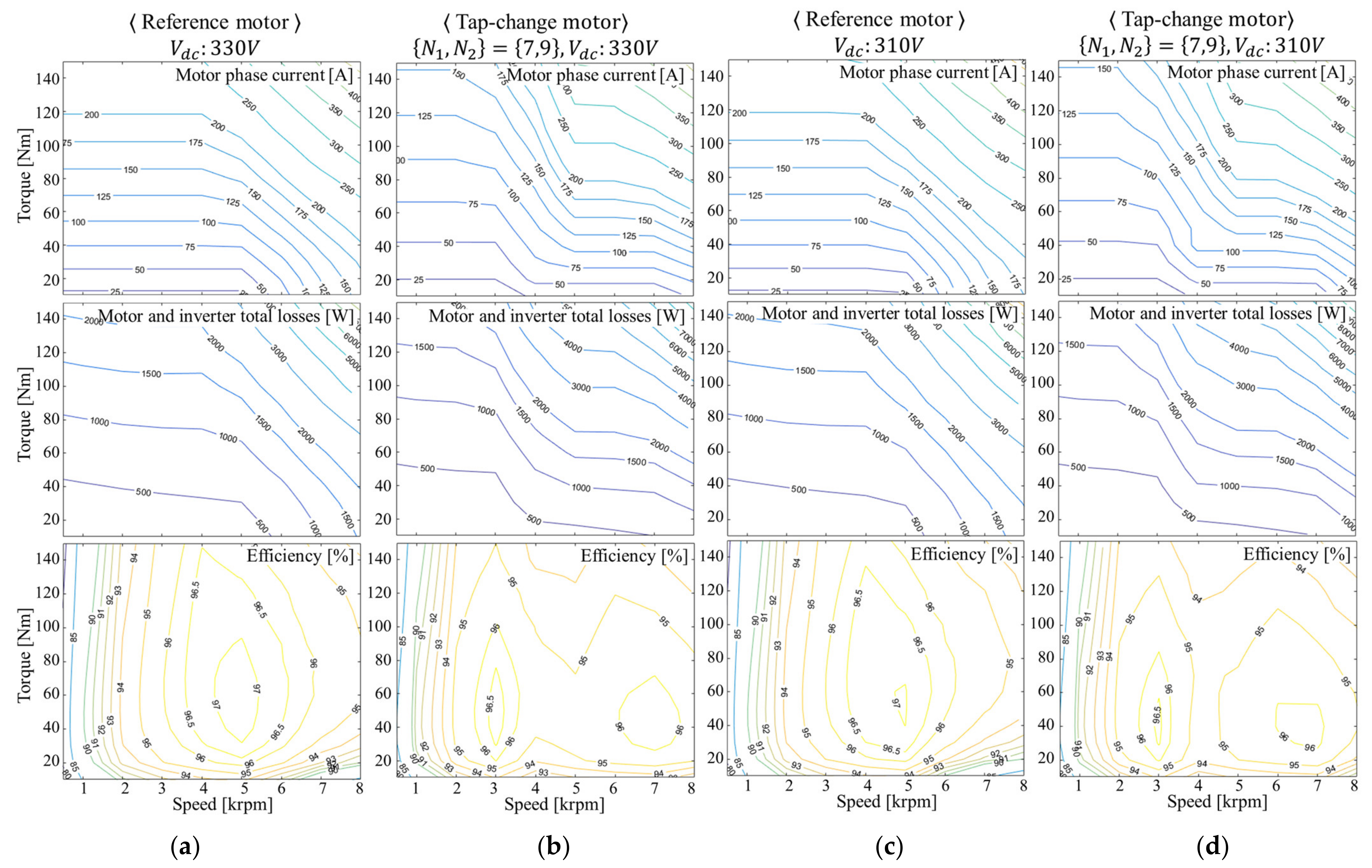
To determine the optimal N 1 and N 2 values, the tap-change motor and inverter losses depending on the winding turn number are modeled. The main loss reduction results from the decrease in the phase current, which introduces inverter and copper losses. However, the variation in the inverter carrier harmonics loss depending on the turn ratio can be a dominant factor when the phase current is low because it generates significantly low inverter and copper losses. Therefore, the motor loss model should include the inverter carrier harmonic loss depending on the winding turn number and operational conditions.

3.1. Motor Losses

Motor losses include copper and core losses. The copper loss occurs in the stator copper windings, and can be expressed as the resistance and the square root of the d- and q-axis current as follows:
P c o p p e r = 3 2 R s i d s 2 + i q s 2
where R s is the stator resistance equal to R s 0 N 1 + N 2 2 / N 0 2 and R s 0 N 1 N 1 + N 2 / N 0 2 in the low-speed and high-speed modes of the tap-change motor, respectively.
PMSM core losses are caused by the fundamental field, stator slot ripples, magnet harmonics, and inverter carrier harmonic voltage [24,25,26]. Because the proposed PMSM is reworked into a tap-change motor based on the reference motor, they have identical physical shapes and characteristics. The core loss due to the fundamental field, stator slot ripples, and magnet harmonics, which are mainly determined by the physical shape, are assumed to be identical. However, the core losses caused by the inverter carrier harmonics voltage are affected by the winding turn number and modulation index. Thus, they should be analyzed to compare the losses of the tap-change motor with those of the reference motor.
The core loss is divided into hysteresis loss and eddy current loss. The core loss per unit weight of the motor is defined as follows [24]:
w i = K e f 2 B p e a k 2 + K h f B p e a k 2
where f and B p e a k   denote the harmonic frequency of the switching frequency f s w and peak core flux density, respectively; K e and K h are the eddy current and hysteresis loss coefficients, respectively. Generally, when the switching frequency is higher than 1 kHz, the eddy current loss becomes significant; therefore, the core loss per unit weight can be expressed as follows:
w i K e f 2 B p e a k 2 = K e f 2 λ p e a k N A 2 = K e V p e a k 2 4 π 2 A 2 N 2
where A , N , λ p e a k and V p e a k denote the flux-path area, winding turn number, peak flux linkage, and applied peak voltage, respectively. Using (15), the core loss for the integer multiple harmonic voltage is expressed by (16), where D and l are the density of the electrical steel plate and flux-path length, respectively.
P c l o s s = K e A l D 4 π 2 A 2 N 2 n = k V n 2
where V n is the n-th harmonic component of the applied inverter output voltage. The harmonic flux affecting the core loss is determined by the harmonic voltage. To analyze the core loss, the sum of the d- and q-axis voltage harmonics squares (SVHS) in the synchronous reference frame is expressed by (17).
S V H S = n = k V n 2 = n = k V d e n 2 + V q e n 2
Figure 6 presents the calculation results of S V H S , which are the sum of the d- and q-axis harmonic voltages from the 25th to 390th harmonics for various modulation indices with space vector modulation. Here, the switching and fundamental frequencies are 10 kHz and 200 Hz, respectively, and k is selected to obtain the minimum and maximum harmonic frequencies of 5 and 78 kHz, respectively. S V H S has a maximum value when the modulation index is approximately 0.6. Hence, the core loss due to the inverter carrier harmonics has a peak value when the modulation index is 0.6. The carrier harmonic core loss can be calculated using (16) and (17), along with Figure 6.
The second loss caused by the harmonic voltage is the magnet eddy current loss [26]. Similar to the eddy current of the core, a magnet eddy current is generated in the rotor permanent magnet because of the inverter carrier harmonics. The magnet eddy current loss is expressed by the following equation in [26].
                              P m e l o s s 2 b d σ δ H p e a k 2 b + a b = d 2 σ μ 0 3 2 π 3 2 f 3 2 V p e a k N A 2 b + a
where a , b , and d denote the width, length, and thickness of the conductor, respectively, and σ , δ = 1 / σ π f μ r μ 0 , and H p e a k denote the conductivity, skin depth, and magnetic field strength, respectively. Because the permanent magnet is aligned on the d-axis of the synchronous reference frame, only the d-axis harmonic voltage affects the magnet eddy current loss, as expressed in (19). Here, the magnet eddy current loss index (MELI) can be expressed as follows:
P m e l o s s = d b + a 2 σ μ 0 3 2 π 3 2 N 2 A 2 n = 1 V d e n 2 f n 3 / 2
M E L I = n = 1 V d e n 2 f n 3 / 2
To analyze the magnet eddy current loss, the MELI is calculated considering the sum of the harmonic voltages of the 25th to 390th orders for various modulation indices at various voltage angles β ( = tan 1 v q s / v d s in degrees, as shown in Figure 7. When the voltage angle β was high, the MELI increased as the modulation index approached 0.5. However, when the voltage angle β was low, the MELI increased as the modulation index approached 1. Based on (6), β is small when i q s and output torque are low. Hence, the magnet eddy current loss is highest at a low load over the rated speed because of the low β and high modulation index. In contrast to the eddy current loss in the motor core, the magnet eddy current loss is affected by both the modulation index and voltage angle β . The magnet eddy current from the carrier harmonics can be calculated using (19) and (20), as well as the results in Figure 7, with the voltage angle β .

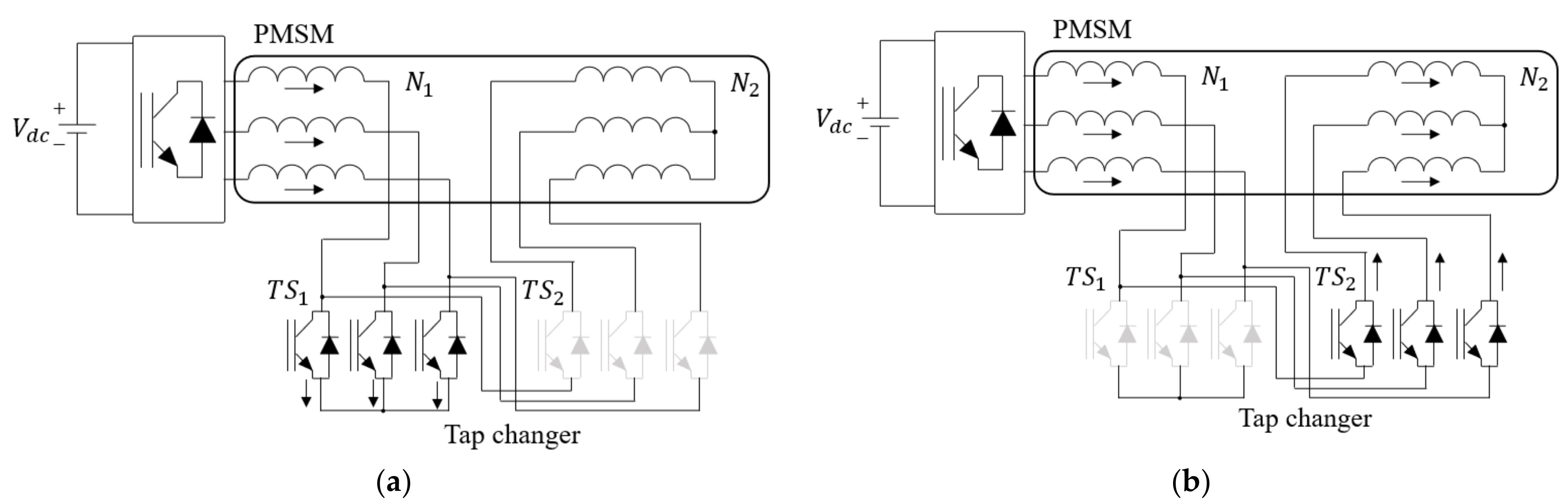
3.2. Three-Phase Inverter and Tap-Change Circuit Losses

A change in the number of stator winding turns directly affects the inverter loss by increasing or decreasing the phase current. Therefore, to improve the motor and inverter efficiency by adjusting the number of stator winding turns of the tap-change motor, the inverter loss must be considered to obtain an accurate solution.
The inverter loss is the sum of the conduction and switching losses P c o n and P s w , respectively [27,28]. The conduction loss P c o n is calculated as the product of the voltage and current of each device. Assuming that the conduction voltage of the IGBT and diode are identical, the conduction voltage can be expressed as a linear function of the conduction current i c using (21) [27,28].
V c e i c = V C E 0 + R c i c
V C E 0 and R c denote the DC offset voltage and resistance component of the conduction state, respectively, and can be approximated from the V-I characteristic diagram in the datasheet of the device. Using (21), the conduction loss due to the d- and q-axis currents in the synchronous reference frame of the three-phase sine wave inverter is calculated as follows:
P c o n = 3 V C E 0 2 i d s 2 + i q s 2 π + R c 2 i d s 2 + i q s 2
Subsequently, the switching loss per switching is determined via linear modeling of the graph of the on and off energy loss versus the device current characteristic plot in the device datasheet [28].
E O N i c = A O N i c + B O N V D C V D C , d a t a s h e e t
E O F F i c = A O F F i c + B O F F V D C V D C , d a t a s h e e t
here, A O N , B O N , A O F F ,   B O F F , and V D C , d a t a s h e e t denote the current correlation coefficients when the switch is turned on and off, the offset at zero current, and the DC voltage presented in the datasheet. These constants can be obtained via linear approximation of the loss energy characteristic diagram in the datasheet of the device. Furthermore, the switching loss of the three-phase inverter with f s w   is expressed as follows:
P s w = f s w 2 A O N + A O F F π i d s 2 + i q s 2 + B O N V D C V D C , d a t a s h e e t
The current path of the tap-change motor includes T S 1 or T S 2 in the high- or low-speed modes, respectively, depending on the operation mode; therefore, this must be included in the copper loss of the motor. Because MOSFETs are used, and only conduction loss in generated in T S 1 and T S 2 , the equivalent resistance can be calculated using R d s O N . Thus, the loss due to the equivalent resistance of the FET can be calculated by adding it to the stator winding resistance in the copper loss calculation.

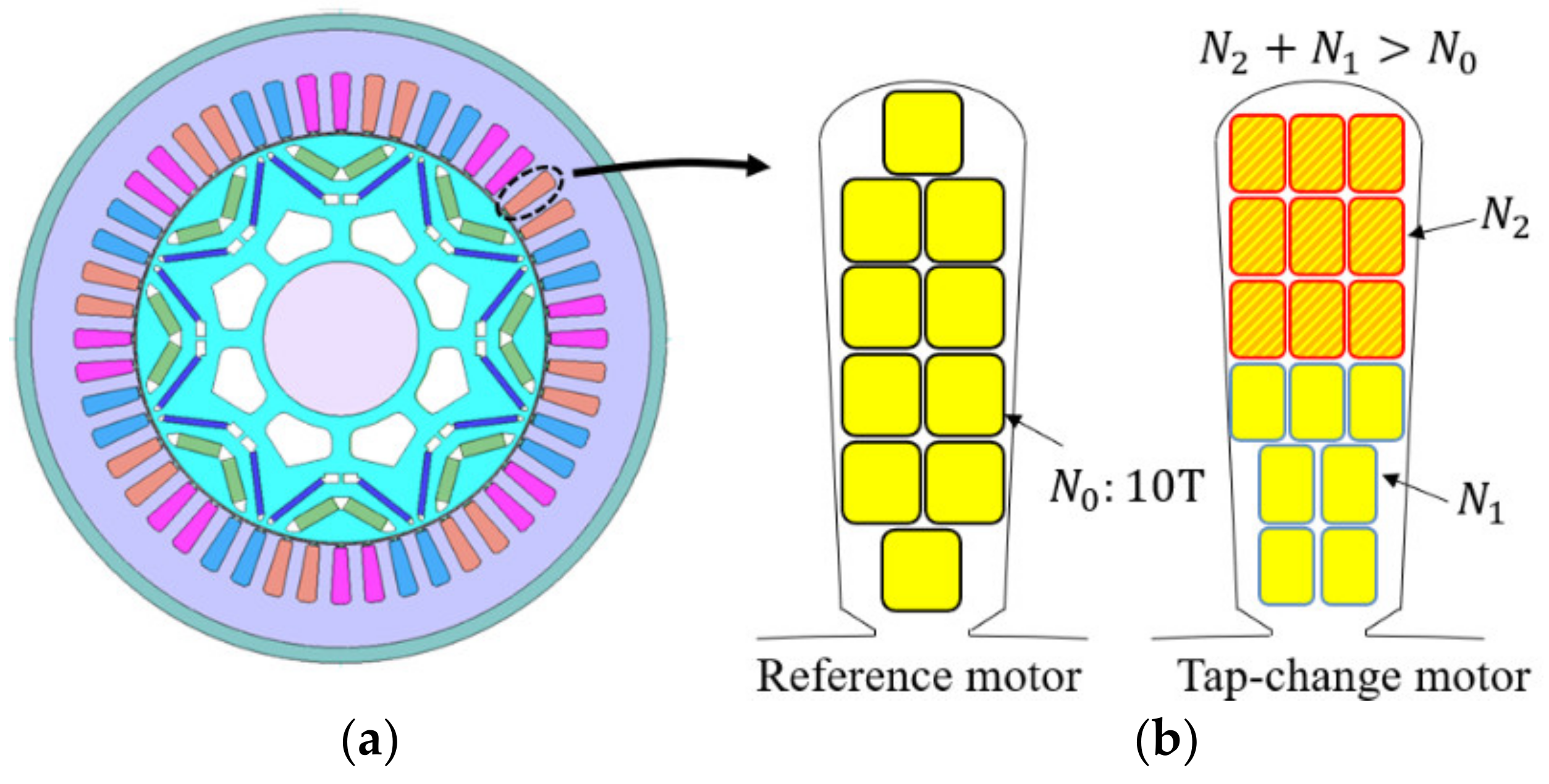
4. Design of Tap-Change Motor Stator Winding Turn Number

4.1. Calculation Process of the Energy Consumption Reduction Rate

The number of turns N 1 and N 2 of the primary and secondary windings must be positive integer values. The motor and inverter losses are calculated by applying various combinations of integers N 1 and N 2 and determining the combination with the least loss. To reduce the number of calculation points, the speed points are discretized into 0, 0.5, 1, 2, 3, 4, 5, 6, 7, and 8 krpm, and the torque points are set to 0, 10, 20, 30, …,130 Nm. The analysis sequence consists of the following four steps.
  • Step 1: Using various turn number combinations { N 1 + N 2 (low-speed mode), N 1 (high-speed mode)}, the minimum d- and q-axis current command values at each operating speed-torque point of the driving cycles is derived based on the flux linkage and torque data from the FEA of the reference motor.
  • Step 2: The total losses are calculated at each operating speed-torque point using the proposed motor and inverter loss model involving the derived current command value from Step 1.
  • Step 3: At each speed-torque point, one drive mode between N 1 + N 2 (low-speed mode) and N 1   (high-speed mode) is selected to have a lower loss.
  • Step 4: With the chosen loss data of the drive mode, the accumulated energy consumption is calculated using the speed-torque frequency of the driving cycles and compared to that of the reference motor.

4.2. Analysis of the Calculated Energy Consumption Reduction Rate

Table 2 presents the analysis results of the energy consumption improvement rate for various combinations N 1 + N 2 ,   N 1 of the tap-change motor with 330 and 310 V battery voltages, which is the DC-link voltage for the inverter. The upper, middle, and bottom portions of Table 2 present the results with the UDDS, HWFET, and the combined UDDS/HWFET driving cycles (55% UDDS and 45% HWFET). Under the UDDS driving cycle, the highest efficiency improvement rates were observed to be 1.86% at N 1 + N 2 ,   N 1 = 17 , 8 with 330 V and 1.76% at N 1 + N 2 ,   N 1 = 16 , 7   with 310 V. As shown in Figure 1a, the UDDS exhibited a frequent acceleration and deceleration in the range of 0 to 30 mph and a high vehicle speed period of over 50 mph between 200 and 300 s. By increasing the turn ratio to 1.6–1.7 in the low-speed mode, the motor and inverter exhibited a lower loss at a rotation lower than 3 krpm, which was 0 to 30 mph for the vehicle. Furthermore, by decreasing the turn ratio to 0.7–0.8 in the high-speed mode, the motor and inverter losses were reduced over 6 krpm, which was over 50 mph. In addition, the lower battery voltage of 310 V, yielded an efficient lower turn ratio compared to that of the higher voltage of 330 V.
For HWFET, the efficiency improvement was expected to be the highest with the observed values of 2.15% at N 1 + N 2 , N 1 = 9 , 7 at 330 V, and 3.38% at N 1 + N 2 , N 1 = 8 , 7 at 310 V. Because the HWFET driving cycle operated at a continuous vehicle speed of over 40 mph, the motor speed was mostly higher than 6 krpm. Thus, a low turn ratio of 0.7–0.9 was beneficial in those speed ranges regardless of the tap-change motor speed mode.
The combined results yielded the highest values of 1.76% at N 1 + N 2 , N 1 = 17 , 8 at 330 V and 2.35% at N 1 + N 2 , N 1 = 16 , 7 at 310 V. By averaging the two battery voltage results, the most efficient turn number was selected to be { N 1 + N 2 ,   N 1 } = {16, 7}; thus, N 1 , N 2 = 7 , 9 .
Figure 8 presents the contour plots of the phase current, motor and inverter loss, and efficiency in the speed-torque plane of the reference motor and the tap-change motor with N 1 , N 2 = 7 , 9 at 330 and 310 V battery voltages, respectively. Plots were obtained without the core loss by the fundamental field, stator slot ripples, and magnet harmonics; thus, the loss and efficiency values shown in Figure 8 are not accurate but are adequate for a characteristic comparison of the reference and tap-change motors. As shown in Figure 8a,c, for the reference motor, the FW control started at approximately 5 krpm, and the motor and inverter losses increased with the FW current. The highest efficiency was observed at values approximately 5 krpm and 60 Nm.
For the tap-change motor, the FW control start speed is different for each speed mode, as shown in Figure 8b,d. The FW starting speeds of the tap-change motor were approximately 3 and 7 krpm in the low- and high-speed modes, respectively, and the highest efficiencies were observed at 3 krpm and 40 Nm, and at 7 krpm and 40 Nm, respectively. Because the highest frequent operating points of UDDS and HWFET were in the 3 krpm and 30 Nm and 7 krpm and 20 Nm regions, the energy consumption was improved, as shown in Table 2.

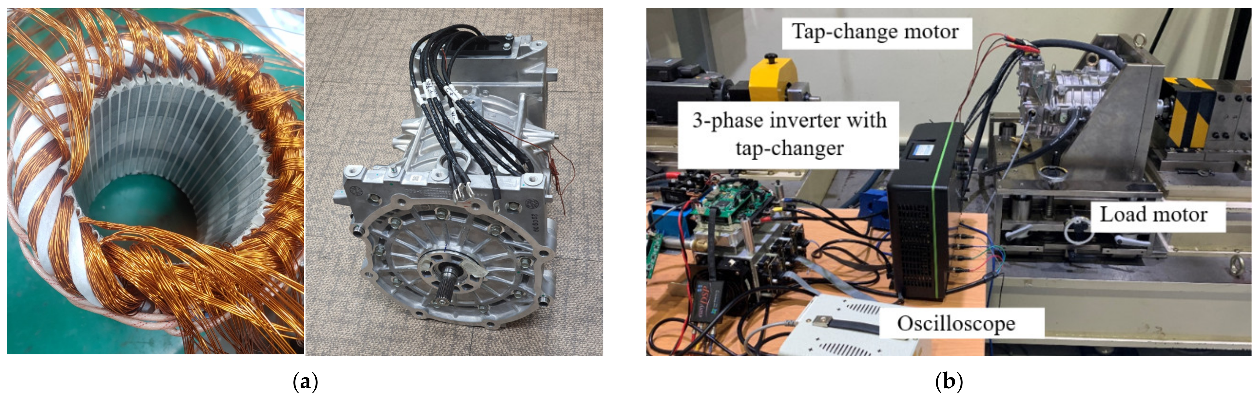
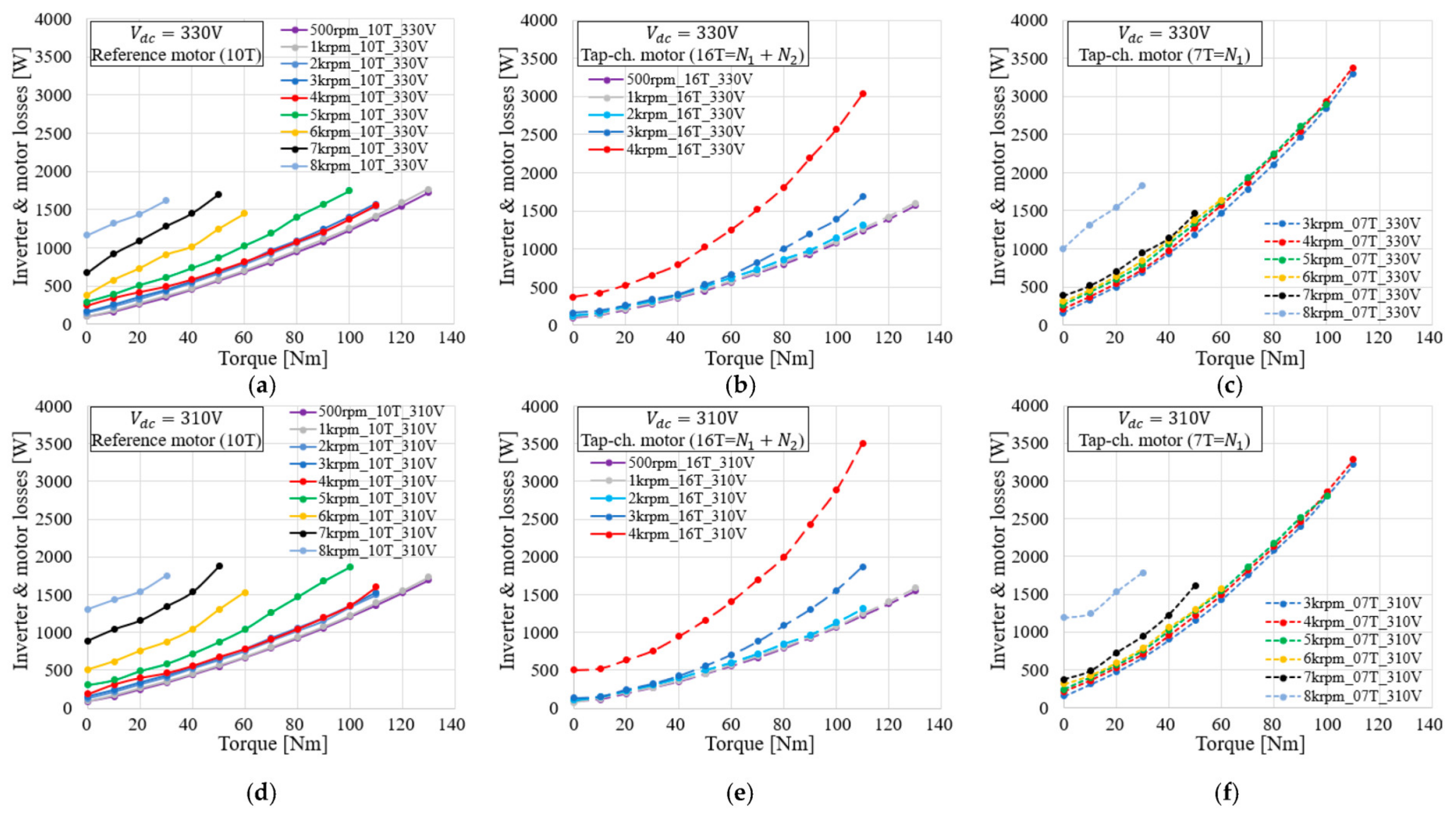
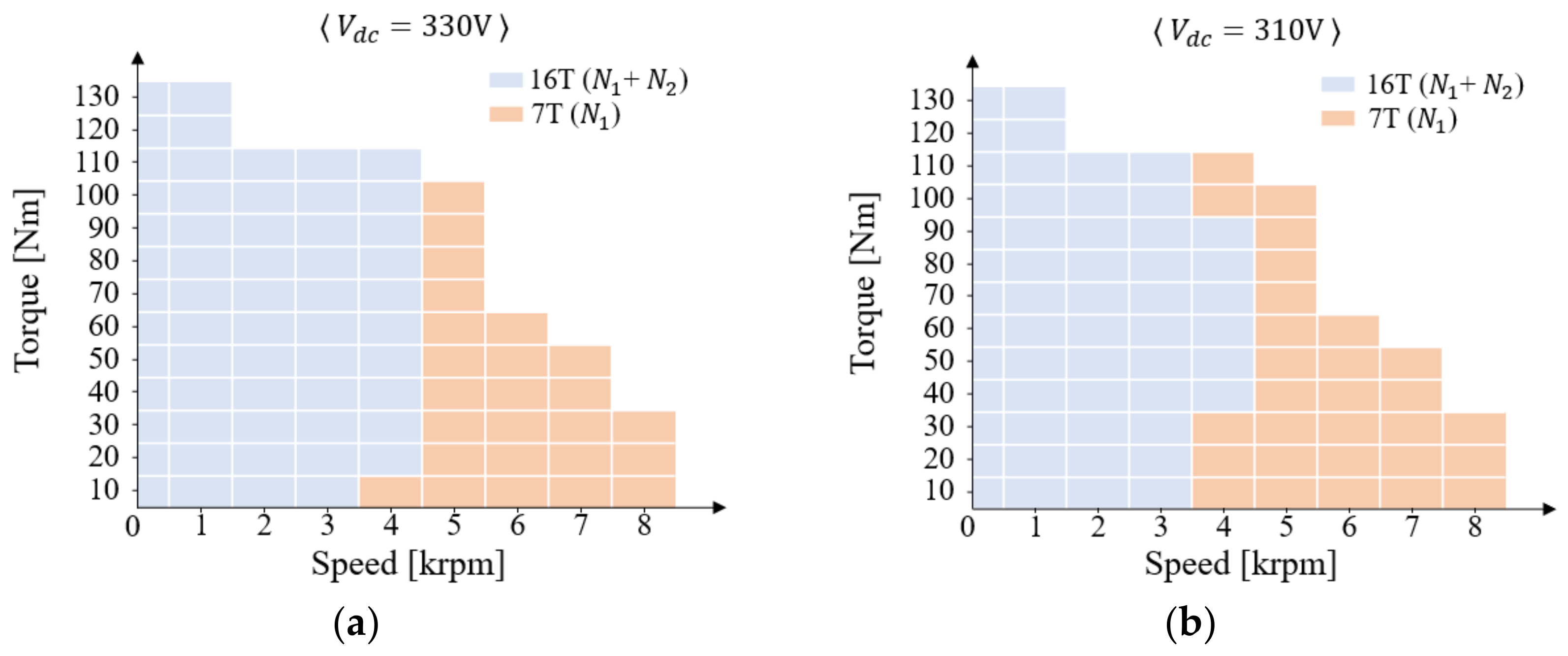
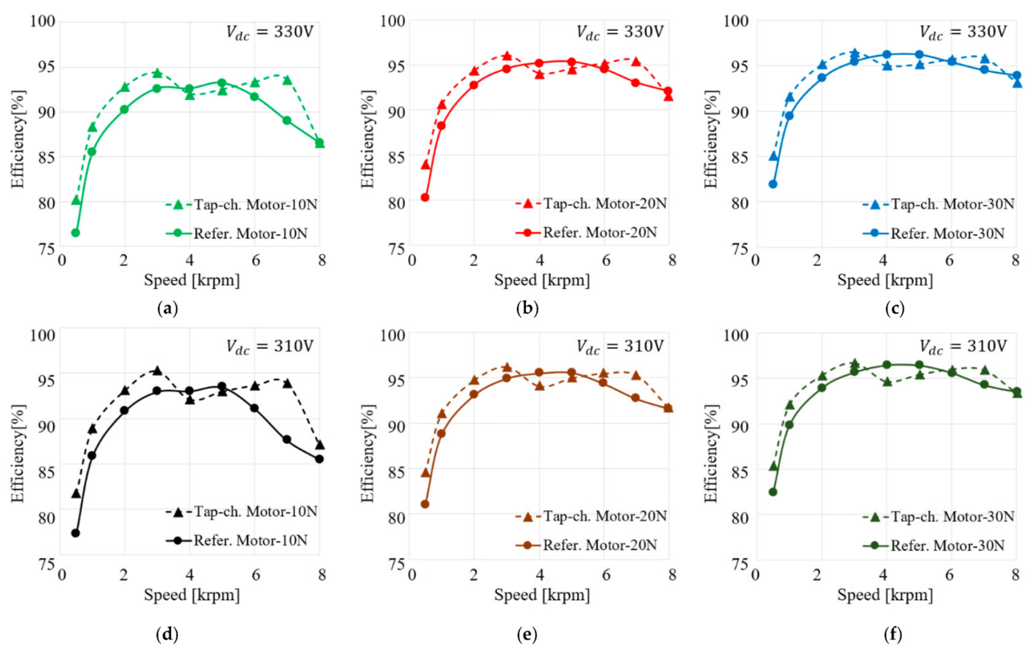
5. Experimental Results

Figure 9a shows images of the tap-change rewound motor implemented using the most energy-efficient turn ratio N 1 , N 2 = 7 , 9 for the combined driving cycle. The total number of winding turns per slot was 16 = N 1 + N 2 , which is larger than N 0 = 10 .   To maintain the same stator slot fill factor as that of the reference motor, the cross-sectional area of the rewound winding was selected to be small, as shown in Figure 4b. Figure 9b demonstrates the experimental setup. The experiments were performed with the reference motor ( N 0 = 10 ) and tap-change motor in the low- ( N 1 + N 2 = 16) and high-speed ( N 1 = 7 ) modes. Furthermore, the mechanical speeds were set at 0.5, 1, 2, 3, 4, 5, 6, 7, and 8 krpm for the driving cycle analysis, and the output torque was tested up to 130 and 30 Nm at low and 8 krpm speeds. Under 3 krpm, the low-speed mode had a lower power loss than the high-speed mode in the presence of a load torque for both 310 and 330 V DC-link voltages; over 5 krpm, the high-speed mode had a lower power loss than the low-speed mode. At approximately 4 krpm, the low- and high-speed modes exhibited efficient intersection points. Hence, the tap-change motor was tested at a speed of 0.5–4 krpm in the low-speed mode, and at a speed of 3–8 krpm in the high-speed mode. Tap-changing points were selected through comparisons of the losses from the two speed modes. Moreover, the snubberless tap-changing method in [19] was adopted to minimize the torque ripple during the tap-changing period of tens of microseconds.
Figure 10 presents the experimental results for the inverter and motor losses versus the output torque. Figure 10a–f show the losses of the reference motor, tap-change motor low-speed mode, and high-speed mode when the DC-link voltage at voltages are 330 and 310 V, respectively. Under 3 krpm, the tap-change motor loss in the low-speed mode was lower than that of the reference motor. However, because the FW starting speed of the tap-change motor in the low-speed mode was lower than that of the reference motor, the total loss increased by approximately 4 krpm due to the FW current.
At speeds of 5 krpm or higher, the reference motor loss tended to increase under the influence of the FW control at the FW and MTPA boundaries; therefore, the high-speed mode loss of the tap-change motor was approximately 6–7 krpm lower compared to that of the reference motor. Generally, the total loss occurring in the tap-change motor and inverter decreased at speeds between 3 krpm and approximately 7 krpm. By contrast, the loss slightly increased at other speeds.
Figure 11 shows the speed mode selection that generates low losses in the speed—torque plane through comparisons of the measured motor and inverter losses. It is a combination of the low- and high-speed modes of the tap-change motor, and the tap-change operation point changes depending on the battery voltage. At 4 krpm, the tap-change motor drive mode was different depending on the motor output torque, and the high-speed mode region widened with a decrease in the battery voltage.
Figure 12 presents the motor and inverter efficiency versus speed when the low- and high-speed modes were combined, as shown in Figure 11. Because the significant driving point of the EV typically exists in the low-torque region, as shown in Figure 3, the efficiency of the reference and tap-change motors were compared for 10, 20, and 30 Nm. The efficiency of the tap-change motor generally yielded peak values at 3 and 7 krpm, and decreased at 4 and 5 krpm. Therefore, despite the efficiency slightly decreasing in the 4 and 5 krpm range, the overall fuel efficiency was expected to be higher when the tap-change motor was applied to the entire driving cycle.
Table 3 presents the calculated average power and energy consumption improvement rate with the experimental results for the UDDS, HWFET, and combined driving cycles. The energy consumption for UDDS and HWFET were improved by 1.84% and 1.53% at 330 V, and 1.16% and 2.15% at 310 V, respectively. Furthermore, the energy consumption of the combined driving cycle was improved by 1.70% and 1.60% at 330 and 310 V, respectively. Here, the average of the combined driving cycles at 330 and 310 V was 1.65%, which was lower than the calculated result (2.01%) for the motor and inverter loss models because a higher loss was generated in the high-speed region. This was presumed to be caused by the magnetic harmonic loss effect occurring in the high-speed region, which was not considered in this study [29].

6. Conclusions

This study proposed a turn number design method for an EV tap-change motor considering the inverter and motor losses over the UDDS, HWFET, and combined driving cycles. Inverter and motor loss models were studied to design an EV tap-change motor with an improved energy efficiency. Thereafter, by calculating the motor and inverter losses involving various turn number combinations, N 1 = 7 and N 2 = 9 were found to be optimal, with a minimum energy consumption during the driving cycles. Furthermore, based on the calculated results, a tap-change motor was implemented by rewinding a mass-produced motor. Subsequently, the feasibility of the design method considering the winding turn number for the EV tap-change motor was experimentally verified. Furthermore, based on comparisons of the energy consumption of the tap-change motor with that of the mass-produced reference motor, the improvement rates over the UDDS, HWFET, and the combined driving cycles were {1.84%, 1.53%, 1.70%} at 330 V and {1.16%, 2.15%, 1.60%} at 310 V.
The tap-change motor requires a tap-changer circuit, which is composed of six solid-state switches. It would be disadvantageous due to the increased cost; however, if the cost of the expensive EV battery capacity and electrical energy consumption can be reduced, the tap-change motor can be a more cost-effective method than the conventional method.

Author Contributions

Conceptualization, B.-G.G. and J.-K.L.; methodology, S.-H.I. and B.-G.G.; software, S.-H.I. and B.-G.G.; validation, S.-H.I. and B.-G.G.; formal analysis, S.-H.I. and B.-G.G.; investigation, B.-G.G. and J.-K.L.; resources, J.-K.L.; writing—original draft preparation, S.-H.I.; writing—review and editing, B.-G.G.; supervision, B.-G.G., J.-K.L. and R.-Y.K.; project administration, B.-G.G. and J.-K.L.; funding acquisition, B.-G.G. and J.-K.L. All authors have read and agreed to the published version of the manuscript.

Funding

This work was supported by the Basic Science Research Program through the National Research Foundation of Korea (NRF) funded by the Ministry of Education (No. 2020R1I1A3A04036842).

Data Availability Statement

Data sharing not applicable.

Conflicts of Interest

The authors declare no conflict of interest.

References

  1. Kim, H.; Chen, H.; Zhu, J.; Maksimovic, D.; Erickson, R. Impact of 1.2 kV SiC-MOSFET EV traction inverter on urban driving. In Proceedings of the IEEE 4th Workshop Wide Bandgap Power Devices and Applications, Fayetteville, NC, USA, 7–9 November 2016; pp. 78–83. [Google Scholar]
  2. Kim, H.; Chen, H.; Maksimovi, D.; Erickson, R. Boost composite converter design based on drive cycle weighted losses in electric vehicle powertrain applications. In Proceedings of the IEEE Energy Conversion Congress & Expo, Milwaukee, WI, USA, 18–22 November 2016; pp. 1–7. [Google Scholar]
  3. Zhang, J.; Xu, L.; Hu, Z.; Liang, C.; Li, J.; Ouyang, M. Optimal sizing of fuel cell electric vehicle powertrain considering multiple objectives. In Proceedings of the IECON 46th Annual Conference of the IEEE Industrial Electronics Society, Singapore, Singapore, 18–21 October 2020; pp. 317–322. [Google Scholar]
  4. United States Environmental Protection Agency. Vehicle and Fuel Emission Testing—Dynamometer Drive Schedule. Available online: www.epa.gov (accessed on 25 December 2022).
  5. Carraro, E.; Morandin, M.; Bianchi, N. Traction PMASR motor optimization according to a given driving cycle. IEEE Trans. Ind. Appl. 2016, 52, 209–216. [Google Scholar] [CrossRef]
  6. Diao, K.; Sun, X.; Lei, G.; Bramerdorfer, G.; Guo, Y.; Zhu, J. System-level robust design optimization of a switched reluctance motor drive system considering multiple driving cycles. IEEE Trans. Energy Convers. 2021, 36, 348–357. [Google Scholar] [CrossRef]
  7. Zhou, X.; Zhu, X.; Wu, W.; Xiang, Z.; Liu, Y.; Quan, L. Multi-objective optimization design of variable-saliency-ratio PM motor considering driving cycles. IEEE Trans. Ind. Electron. 2021, 68, 6516–6526. [Google Scholar] [CrossRef]
  8. Pastellides, S.; Gerber, S.; Wang, R.J.; Kamper, M. Evaluation of drive cycle-based traction motor design strategies using gradient optimization. Energies 2022, 15, 1095. [Google Scholar] [CrossRef]
  9. Sun, X.; Shi, Z.; Cai, Y.; Lei, G.; Guo, Y.; Zhu, J. Driving-cycle-oriented design optimization of a permanent magnet hub motor drive system for a four-wheel-drive electric vehicle. IEEE Trans. Transp. Electrific. 2020, 6, 1115–1125. [Google Scholar] [CrossRef]
  10. Miller, J.M. Propulsion Systems for Hybrid Vehicles; IET: London, UK, 2010; pp. 293–294. [Google Scholar]
  11. Kume, T.; Sawa, T.; Sawamura, M.; Zenke, M. Inverter driving method for induction motors. U.S. Patent 4,916,376, 10 April 1990. [Google Scholar]
  12. Chen, C.H.; Cheng, M.Y.; Tsai, M.S. Study on a wide speed range integrated electrical transmission system. In Proceedings of the International Conference on Power Electronics and Drives Systems, Kuala Lumpur, Malaysia, 28 November–1 December 2005; pp. 781–786. [Google Scholar]
  13. Hsieh, M.F.; Hsu, F.S.; Dorrell, D.G. Winding changeover permanentmagnet generators for renewable energy applications. IEEE Trans. Magn. 2012, 48, 4168–4171. [Google Scholar] [CrossRef]
  14. Shi, P.; Cui, X.; Zhu, L. A SCR-based switch-control strategy of delta/wye switchover for delta connected induction motors. In Proceedings of the 7th International Conference on Power Electronics and Motion Control, Harbin, China, 2–5 June 2012; pp. 2607–2611. [Google Scholar]
  15. Shin, Y.; Cho, S.; Jung, H.; Park, J.; Shin, W.; Kim, D.; Park, S.; Choi, S. A thyristor-based seamless winding changeover circuit for high efficiency of electric vehicle drive system. In Proceedings of the 10th International Conference on Power Electronics and ECCE Asia, Busan, Korea, 27–30 May 2019; pp. 1274–1279. [Google Scholar]
  16. Kume, T.; Iwakane, T.; Sawa, T.; Yoshida, T.; Nagai, I. A wide constant power range vector-controlled AC motor drive using winding changeover technique. IEEE Trans. Ind. Appl. 1991, 27, 934–939. [Google Scholar] [CrossRef]
  17. Swamy, M.M.; Kume, T.; Maemura, A.; Morimoto, S. Extended high speed operation via electronic winding-change method for AC motors. IEEE Trans. Ind. Appl. 2006, 42, 742–753. [Google Scholar] [CrossRef]
  18. Takatsuka, Y.; Hara, H.; Yamada, K.; Maemura, A.; Kume, T. A wide speed range high efficiency EV drive system using winding changeover technique and SiC devices. In Proceedings of the IPEC-Hiroshima 2014—ECCE Asia, Hiroshima, Japan, 18–21 May 2014; pp. 1898–1903. [Google Scholar]
  19. Im, S.H.; Gu, B.G. A snubberless solid-state tap changer for permanent magnet synchronous motors. IEEE Trans. Power Electron. 2020, 35, 12143–12152. [Google Scholar] [CrossRef]
  20. Li, A.; Jiang, D.; Sun, X.; Liu, Z. Online drive topology conversion technology for PMSM speed range extension. IEEE Trans. Power Electron. 2022, 37, 7113–7121. [Google Scholar] [CrossRef]
  21. Cheng, L.J.; Tsai, M.C. Robust scalar control of synchronous reluctance motor with optimal efficiency by MTPA control. IEEE Access 2021, 9, 32599–32612. [Google Scholar] [CrossRef]
  22. Sepulchre, L.; Fadel, M.; Pietrzak-David, M.; Porte, G. MTPV Flux-Weakening Strategy for PMSM High Speed Drive. IEEE Trans. Ind. Appl. 2018, 54, 6081–6089. [Google Scholar] [CrossRef]
  23. Xu, Y.; Morito, C.; Lorenz, R.D. Extending high-speed operating range of induction machine drives using deadbeat-direct torque and flux control with precise flux weakening. IEEE Trans. Ind. Appl. 2019, 55, 3770–3780. [Google Scholar] [CrossRef]
  24. Yamazaki, K.; Seto, Y. Iron loss analysis of interior permanent-magnet synchronous motors-variation of main loss factors due to driving condition. IEEE Trans. Ind. Appl. 2006, 42, 1045–1052. [Google Scholar] [CrossRef]
  25. Yamazaki, K.; Abe, A. Loss investigation of interior permanent-magnet motors considering carrier harmonics and magnet eddy currents. IEEE Trans. Ind. Appl. 2009, 45, 659–665. [Google Scholar] [CrossRef]
  26. Yamazaki, K.; Takaki, Y. Iron loss analysis of permanent magnet motors by considering minor hysteresis loops caused by inverters. IEEE Trans. Magn. 2019, 55, 1300304. [Google Scholar] [CrossRef]
  27. Graovac, D.; Purschel, M. IGBT Power Losses Calculation Using the Data-Sheet Parameters. Infineon Application Note. 2009. Available online: https://community.element14.com/products/manufacturers/infineon/w/documents/6572/igbt-power-losses-calculation-using-the-data-sheet-parameters (accessed on 25 December 2022).
  28. Infineon Application Note, Calculation of Major IGBT Operating Parameters. ANIP9931E. 1999. Available online: https://pdf4pro.com/cdn/calculation-of-major-igbt-operating-21a8fc.pdf (accessed on 25 December 2022).
  29. Yamazaki, K.; Takeuchi, H. Impact of mechanical stress on characteristics of interior permanent magnet synchronous motors. IEEE Trans. Ind. Appl. 2017, 53, 963–970. [Google Scholar] [CrossRef]
Figure 1. (a) Urban Dynamometer Driving Schedule (UDDS) and (b) Highway Fuel Economy Test (HWFET) driving cycle.
Energies 16 00412 g001
Figure 2. Tap-change motor configuration modes: (a) high-speed and (b) low-speed.
Energies 16 00412 g002
Figure 3. Distribution of significant driving points on the speed and torque plane with combined driving cycle (55% UDDS and 45% HWFET).
Energies 16 00412 g003
Figure 4. (a) Cross-sectional view of the PMSM and (b) the conductors in a slot of the reference motor (left) and tap-change motor (right).
Energies 16 00412 g004
Figure 5. Comparison of the voltage limit and current vector at 3 krpm and 7 krpm with (a) n = 1, (b) n = 1.6, and (c) n   = 0.7.
Energies 16 00412 g005
Figure 6. Variation of the sum of the d- and q-axis voltage harmonic square with the modulation index of the 25th–390th harmonics when the switching and fundamental frequencies are 10 kHz and 200 Hz, respectively.
Energies 16 00412 g006
Figure 7. Variation of magnet eddy current index with modulation index of the 25th–390th harmonics when the switching and fundamental frequencies are 10 kHz and 200 Hz, respectively.
Energies 16 00412 g007
Figure 8. Motor phase current, total losses, and efficiency on speed and torque plane with the (a) reference motor ( V d c : 330 V), (b) tap-change motor ( V d c : 330 V), (c) reference motor ( V d c : 310 V), and (d) tap-change motor ( V d c : 310 V).
Energies 16 00412 g008
Figure 9. (a) Rewiring of the tap-change motor and (b) experimental setup.
Energies 16 00412 g009
Figure 10. Experimental results of the inverter and motor losses with the (a) reference motor, (b) low-speed mode of the tap-change motor, (c) high-speed mode of the tap-change motor with V d c = 330 V, (d) reference motor, (e) low-speed mode of the tap-change motor, (f) high-speed mode of the tap-change motor with V d c = 310 V.
Energies 16 00412 g010
Figure 11. Speed mode selection of the tap-change motor on the speed and torque plane with (a) V dc = 330   V and (b) V dc = 310   V .
Energies 16 00412 g011
Figure 12. Experimental results. Comparison of the efficiency of the tap-change motor and reference motor at different speeds and torque conditions: (a) 10 Nm, (b) 20 Nm, (c) 30 Nm with V d c = 330   V , and (d) 10 Nm, (e) 20 Nm, (f) 30 Nm with V d c = 310   V .
Energies 16 00412 g012
Table 1. Reference motor parameters.
ParameterValueUnit
Pole number8
Maximum output power150kW
Stator out diameter200mm
Rotor diameter132mm
Height175mm
Number of slots48
Winding turn number per slot10
Number of windings per phase8
Stator phase resistance Rs10.8m Ω
Table 2. Energy consumption reduction rate results.
Improvement Rate [%]
Battery Voltage: 330 V
Improvement Rate [%]
Battery Voltage: 310 V
UDDSN1UDDSN1
5678956789
N1 + N211−0.96−0.69−0.48−0.53−0.96N1 + N211−0.58−0.28−0.10−0.39−0.99
12−0.180.130.350.33−0.09120.190.510.730.45−0.17
130.430.761.001.010.57130.580.921.180.890.26
140.671.021.301.310.87140.671.081.411.180.62
150.691.101.451.511.14150.741.231.621.460.96
160.711.191.611.731.40160.731.321.761.641.15
170.651.241.701.861.56170.531.171.661.561.06
180.461.091.591.781.50180.050.751.281.210.70
190.010.701.251.471.1919−0.470.280.910.900.42
20−0.500.250.821.130.8920−0.96−0.080.570.620.19
HWFETN1HWFETN1
5678956789
N1 + N260.83----N1 + N262.29----
71.631.64---73.023.04---
81.751.802.03--82.763.163.38--
91.401.852.151.90-92.432.933.352.58-
100.941.542.061.960.82102.152.923.372.580.80
110.671.482.031.930.77112.002.813.292.520.72
120.501.371.941.870.72121.872.723.262.480.63
130.371.271.901.850.66131.762.653.222.420.51
140.251.191.851.800.57141.652.583.162.340.39
150.141.121.791.740.48151.552.523.112.280.28
CombinedN1CombinedN1
5678956789
N1 + N211−0.230.290.650.58−0.18N1 + N2110.581.111.430.92−0.22
120.120.691.071.030.28120.951.511.871.370.19
130.400.991.401.390.61131.111.702.101.580.37
140.481.101.541.530.74141.111.762.201.700.52
150.441.111.611.610.84151.101.812.291.820.65
160.411.121.671.710.95161.061.832.351.900.71
170.341.121.701.761.01170.921.732.271.830.60
180.191.011.611.690.93180.621.472.041.600.35
19−0.090.781.411.500.73190.301.191.821.400.14
20−0.400.501.151.290.52200.000.971.611.22−0.04
Table 3. Experimental results: energy consumption improvement rate.
Battery Voltage330 V310 V
Reference motor
average power
UDDS3.33 kW3.31 kW
HWFET10.81 kW10.86 kW
Tap-change motor average powerUDDS3.27 kW3.27 kW
HWFET10.65 kW10.63 kW
Energy consumption reduction rateUDDS1.84%1.16%
HWFET1.53%2.15%
Comb.1.70%1.60%
Calculated energy
consumption reduction rate
(Table 2)
UDDS1.61%1.76%
HWFET1.74%3.06%
Comb.1.67%2.35%
Disclaimer/Publisher’s Note: The statements, opinions and data contained in all publications are solely those of the individual author(s) and contributor(s) and not of MDPI and/or the editor(s). MDPI and/or the editor(s) disclaim responsibility for any injury to people or property resulting from any ideas, methods, instructions or products referred to in the content.

