Abstract
In this paper, a module-combined stator is proposed, which is used for large and ultra-low-speed permanent magnet synchronous motors, and the influence of stator core seams on the no-load performance is studied. A method is proposed to weaken the negative influence of stator iron core seams on the no-load performance of permanent magnet synchronous motors. Firstly, the magnetic circuit model of the motor considering the stator iron core seams was deduced theoretically, and the selection principle of stator core seam number was given a description. The influence of different seam parameters on the no-load performance and the influence of different pole-slot fits and the number of parallel branches on the no-load performance are analyzed. The proposed structure of the stator iron core, which can weaken the influence of stator iron core seams on the no-load performance of the motor, is proposed. Using analysis and simulation experiments, the effectiveness of the proposed stator iron core structures in weakening the negative influence of the stator iron core seams on the no-load performance was verified.
1. Introduction
For large and ultra-low-speed motors, module-combined stator permanent magnet motors are used to reduce the assembly difficulty and improve the fault tolerance [1,2,3]. The stator module combination structure of permanent magnet motors has three main schemes:
Scheme 1: A single set of stator teeth and a stator yoke are superposed to form a tooth–yoke sub-module, and the coil is wound on the tooth–yoke sub-module [4,5];
Scheme 2: A stator sector piece with a single set of stator teeth is separately superposed onto a sub-module stator, and the wound coil is directly wound onto the stator tooth module. This stator tooth module and the stator yoke are fixed via a separate connecting piece or a pigeon tail slot on the stator sheet [6,7];
Scheme 3: A stator sector piece that can wind one group of three-phase windings is separately superposed into a sub-module stator. The windings are wound on a single tooth when the seams of the stator core module are in the yoke and the pitch y = 1, while the seams of the stator core module are in the tooth or pitch Y > 1. The windings are divided into two different span specifications: large and small-span windings [8,9,10,11,12].
A novel cogging torque mitigation method for modular permanent magnet (PM) machines with flux gaps in alternate stator teeth has been proposed [13,14]. The influence of these flux gaps on the electromagnetic performance of modular PM machines, such as on the winding factor, open-circuit air-gap flux densities, back electromotive force, cogging torque, on-load torque, inductance, magnetic saturation and copper losses, were comprehensively investigated and general rules have been established [15].
In this paper, a module-combined stator is proposed for large and ultra-low-speed permanent magnet synchronous motors, and the influence of the stator core seams was studied. For large and ultra-low-speed motors (<60 rpm), copper loss (>80% total loss) is mainly dependent on the no-load back electromotive force and the same coil parameters and cogging torque can significantly influence the motor parameter measurement accuracy of the converter; therefore, this paper mainly studied the performance of the no-load back electromotive force and cogging torque. Firstly, a magnetic circuit model considering the stator core seams was established. The effect of the dimension parameters of the seams on the no-load performance of the motor was studied using different pole slot fits and number of parallel branches. Based on the comparison of the effects of different parts of the stator core seams, two kinds of stator sheet structures are proposed to weaken the adverse effects of the stator core seams.
2. Magnetic Circuit Model with Consideration of Stator Core Seams
A schematic of stator core seams with an outer rotor permanent magnet surface mounting motor is given in Figure 1. In the enlarged view around the stator core seams in Figure 1b, Nseam is the seam number; hj2 is the height of the rotor yoke; hm and r2 are the inner diameter and thickness of the permanent magnet, respectively; g0 is the air gap between the stator and rotor; h01 and b01 are the height and width of the stator notch, respectively; bt is the regular tooth width; bt11 and bt12 are the left tooth width and the right tooth width, respectively, with the seam on the tooth; bseam is the seam width; r1 is the radius of the slot bottom; hj1 is the height of the stator yoke; and hs1 is the radial projection height from the slot shoulder bottom to the slot notch.
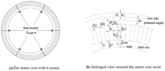
Figure 1.
The schematic drawing of stator with seams (Nseam = 6).
2.1. The Selection Principle of Seam Number
The number of slots per pole per phase in a multi-pole, ultra-low-speed permanent magnet synchronous motor with fewer slots is shown in Expression (1).
where q is the number of slots per pole per phase, QS is the number of stator slots, p is the number of motor pole pairs, m is motor phase, and c and d are the minimum forms of the numerator or denominator.
The maximum number of pole phase groups is 2p/d. When d is even, the value of seam number Nseam should be the divisor of 2p/d because the large span coil must connect at least one pole phase group as shown in Figure 2a. When d is odd, the value of seam number Nseam should be the divisor of p/d because the large span coil must connect at least two pole phase groups as shown in Figure 2b.
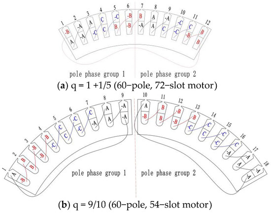
Figure 2.
Pole phase groups with two different pole slot combinations.
2.2. The Magnetic Circuit
The magnetic circuit model considering the stator core seams is given in Figure 3. In order to facilitate the modeling, the following assumptions were made:
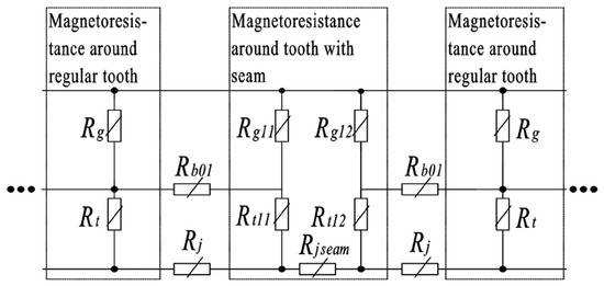
Figure 3.
Distribution of air gaps and stator magnetoresistance around the stator core seam.
- The flux in the left tooth and right tooth with the seam on the tooth are linearly proportional to the tooth width;
- The magnetic resistance of each segment was simplified to a rectangle in the calculation of the magnetic resistance;
- The magnetic permeability of the ferromagnetic material was set to be invariable, and the corresponding magnetic resistance was assumed to be invariable.
In Figure 3, Rg is the equivalent air gap magnetoresistance corresponding to the regular tooth; Rg11 and Rg12 are the equivalent air gap magnetoresistances corresponding to the left and right tooth with the seam, respectively; Rb01 is the stator slot leakage magnetoresistance; Rt is the regular tooth magnetoresistance; Rb01 is the stator slot leakage magnetoresistance; Rt11 and Rt12 are the left and right tooth magnetoresistances with the seam, respectively; Rj is the regular stator yoke magnetoresistance; and Rjseam is the stator yoke magnetoresistance with the seam.
The expression of magnetoresistance R is shown in (2), where l is the length of the magnetic path, μ is the magnetoconductivity of the medium, and S is the sectional area of the medium.
Based on the expression (2), Rg, Rg11, and Rg12 can be expressed as:
where kδ and kδ1 are the air gap coefficients corresponding to the regular stator tooth and stator tooth with the seam, respectively; g0 is the air gap between stator and rotor, μ0 is the vacuum magnetic permeability, r2 is the inner diameter of rotor yoke, hm is the magnetization direction length of permanent magnets, LFe is the iron core length of the stator and rotor, bt11 is the tooth width on the left of the seam, and bt12 is the tooth width on the right of the seam. Referring to reference [16,17,18], kδ and kδ1 can be expressed as:
where b01 is the width of the top stator slot, and bseam is the width of the stator core seam. The stator tooth magnetoresistance and yoke magnetoresistance can be expressed as follows, where μFe is the relative magnetic permeability of the stator:
where r1 is the outer diameter of the stator yoke, μfe is the magnetic permeability of the stator core, bt is the width of the stator tooth without seam, and hj1 is the radial height of the stator yoke.
3. Influence of Seams on No-Load Performance
3.1. Influence of Different Seam Numbers and Seam Widths on No-Load Performance
The motor parameters are given in Table 1. The winding end connection diagram is shown in Figure 4 in the case of Nseam = 3, a = 3, aUnit = 1 and Nseam = 6, a = 6, aUnit = 1, where a is the number of parallel branches of the whole stator and aUnit is the number of parallel branches of one stator sub-module. The influence of the seam number Nseam and the seam width bseam on the no-load motor performance is shown in Figure 5. It can be seen from Figure 5 that:

Table 1.
Parameters of the 60-pole 72-slot motor.
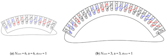
Figure 4.
Single-stator unit winding end connection diagram with different Nseam values.
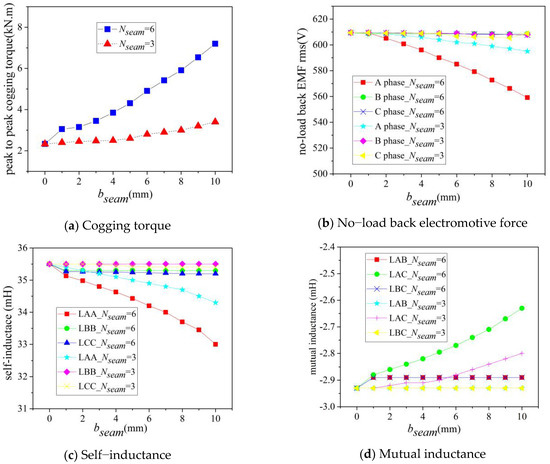
Figure 5.
The relationships of no-load performance using different seam numbers and seam widths.
- (1)
- The cogging torque amplitude was directly proportional to the seam number Nseam and the seam width bseam;
- (2)
- The effective value of no-load phase back electromotive force, the amplitude of the self-inductance, and mutual inductance were inversely proportional to the seam number Nseam and the seam width bseam;
- (3)
- The self-inductance LAA and mutual inductance LAC of A phase, which were closest to the seam, were the most affected by the seam number Nseam and the seam width bseam because the maximum mutual inductance variation extent (0.35 mH), which is influenced by the seam number Nseam and the seam width bseam, has little influence on motor performance; the mutual inductances that are influenced by the seam number Nseam and the seam width bseam are ignored in the following chapters.
3.2. The Relationship between Motor No-Load Performance and the Number of Parallel Branches in One Unit with Same Seam
Winding end connection diagram with two parallel branches in one stator unit are shown in Figure 6, Where Nseam = 6, a = 12, aUnit = 2. The no-load performance with a different number of parallel branches in one stator unit aUnit is shown in Figure 7; the no-load cogging torque is not shown because the stator winding connection style had no influence on it. The winding end connection diagrams with aUnit = 1 and aUnit = 2 are shown in Figure 4a and Figure 6, respectively.
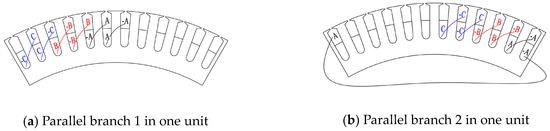
Figure 6.
Winding end connection diagram with two parallel branches in one stator unit (Nseam = 6, a = 12, aUnit = 2).
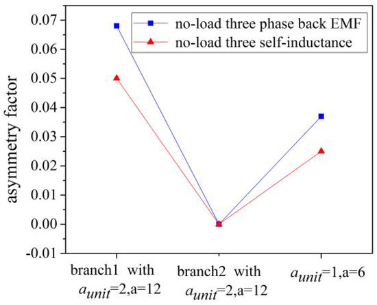
Figure 7.
Asymmetry factor of no-load three-phase back electromotive force and self-induction using different motor parallel branches (bseam = 5 mm).
Additionally, the asymmetry factor for the back electromotive force in this paper is max{|EA − Eav|;|EB − Eav|;|EC − Eav|} and the asymmetry factor for self-inductance is max{|LAA − Lav|;|LBB − Lav|;|LCC − Lav|}, where EA is the effective values of A phase winding no-load back electromotive force, EB is the effective values of B phase winding no-load back electromotive force, EC is the effective values of C phase winding no-load back electromotive force, Eav = (EA + EB + EC)/3; LAA, LBB, LCC are the average no-load self-inductance value of A phase winding, B phase winding, and C phase winding, respectively, and Lav = (LAA + LBB + LCC)/3.
It can be seen from Figure 7 that the asymmetry factor of the no-load three-phase back electromotive force’s effective values and the inductance were inversely proportional to the number of parallel branches in one stator unit aUnit.
3.3. The Relationship between Motor No-Load Performance and Slot–Pole Combination with Same Seam Parameters
The stator winding wiring diagrams with different pole slots are shown in Figure 8, where the winding wiring diagram of a 60-pole, 54-slot stator is divided into two kinds according to the position of the seam on the A phase winding. The no-load performance, which is shown in Figure 9, showed that:
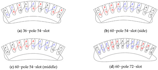
Figure 8.
Stator winding wiring diagram with different pole slots (Nseam = 6, a = 6, aUnit = 1).
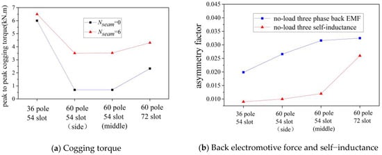
Figure 9.
The relationship between no-load motor performance and slot–pole combination (bseam = 5 mm).
- (1)
- More stator slots with the same rotor poles can weaken the no-load motor performance impact of seams: with the same 54-slot stator sheet parameter, the no-load motor performance impact of a seam with the 36-pole scheme was less than the 60-pole scheme; with the same 60-pole rotor parameter, the no-load motor performance impact of a seam with a 72-slot scheme was less than that of a 54-slot scheme;
- (2)
- When the number of stator teeth that continuously wind the same phase coil in one polar phase group was more than three, the seam on the side of the same phase coil tooth weakened the no-load motor performance impact of the seam. The no-load motor performance impact of the seam in Figure 8b was less than that in Figure 8c, where the seam is in the middle of the same phase coil tooth.
In conclusion, the following electromagnetic parameters can weaken the no-load motor performance impact of seams:
- (1)
- Reduce the number of the stator core seams and width of the stator core seams;
- (2)
- Reduce the number of parallel branches in one stator sub-module;
- (3)
- Adopt fewer poles and more slots;
- (4)
- When the number of stator teeth that continuously wind the same phase coil in one polar phase group is more than three, place the seam on the same side as the phase coil tooth.
4. Stator Sheet Structures That Can Weaken the Impact of Seams
4.1. No-Load Motor Performance Impact of Seams on Different Parts of Tooth
Figure 10 shows a schematic drawing of a seam on different parts of tooth. The corresponding results, which are shown in Figure 11, showed that:
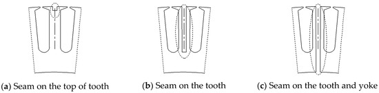
Figure 10.
Schematic drawing of a seam on a stator core.
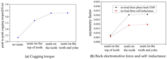
Figure 11.
The corresponding no-load performance of seam location on stator core (Nseam = 6, bseam = 5 mm, a = 6).
- (1)
- The no-load cogging torque was chiefly affected by a seam on the top of the tooth (compare Figure 10a,c);
- (2)
- The no-load back electromotive force and self-inductance were mainly affected by a seam on the top of the tooth (compare Figure 10a–c);
- (3)
- The no-load motor performance impact of a seam on the yoke was negligible (compare Figure 10b,c).
4.2. Proposed New Stator Sheet Structures
According to the conclusions from Section 3.1, the new stator sheet structures, which are shown in Figure 12, adopt the method of an opening auxiliary seam on the top of the tooth to balance the no-load cogging torque impact of a seam, and narrow the tooth or auxiliary seam on the whole tooth to balance the no-load back electromotive force and self-inductance. In Figure 12, the width of narrow tooth btz = bt11 + bt12 = bt − bseam.
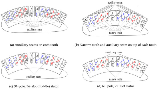
Figure 12.
Stator winding wiring diagrams with different pole slots (Nseam = 6, a = 6, aUnit = 1).
Figure 13 shows that:
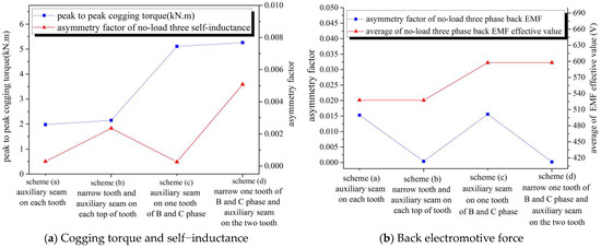
Figure 13.
Comparison of no-load performance with auxiliary seam and narrow tooth (bseam = 5 mm).
- (1)
- Compared with the narrow tooth and auxiliary seam on the top of the tooth scheme (Figure 12b,d), an auxiliary seam (Figure 12a,c) was better at weakening the no-load cogging torque and self-inductance impact of the seam but worse at weakening the no-load asymmetry factor of the back electromotive force impact of the seam;
- (2)
- Compared with one tooth of B and C phase with an auxiliary seam or narrow tooth (Figure 12c,d), each whole tooth with an auxiliary seam or narrow tooth (Figure 12a,b) weakened the no-load cogging torque and self-inductance impact of the seam better, but reduced the back electromotive force value more.
Learning from the strengths and weaknesses shown in Figure 12, Figure 14 was proposed on the basis of Figure 12b,d. An auxiliary seam 2 was added to balance the air-gap magnetic field to reduce the negative impact of the seam on the cogging torque, where the width of auxiliary seam 2 is equal to the width of auxiliary seam 1.
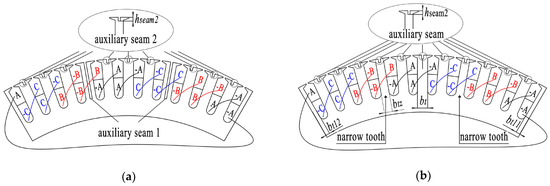
Figure 14.
Winding end connection diagram with double auxiliary seams scheme (Nseam = 6, aUnit = 1). (a) Auxiliary seam 1 on one tooth of B and C phase and auxiliary seam 2 on other tooth, (b) Narrow tooth of B and C phase + auxiliary seam 1 on the narrow tooth + auxiliary seam 2 on the other tooth.
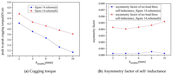
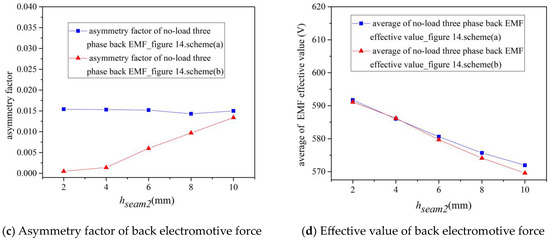
Figure 15.
The corresponding no-load performance with double auxiliary seam scheme and different hseam2 (bseam = 5 mm).
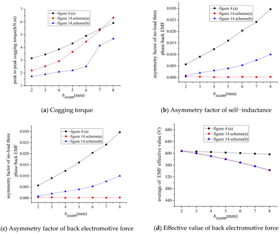
Figure 16.
The corresponding no-load performance using double auxiliary seam scheme and different bseam (hseam2 = 6 mm).
- (1)
- (2)
- Increasing the height of auxiliary seam hseam2 can weaken the no-load cogging torque, but increase the asymmetry factor of no-load back electromotive force and decrease the value of no-load back electromotive force;
- (3)
- When the seam width bseam is increased (Figure 16), the cogging torque decreased to a smaller degree, and the asymmetry factor decreased, while no-load self-inductance and phase electromotive force remained nearly constant. Both schemes decreased the effective value of the back electromotive force to a greater degree, especially the Figure 14b scheme.
The disadvantage of the Figure 14a scheme is that auxiliary seam 1 produces difficulties on the core, especially if the seam width bseam is too small. The disadvantage of the Figure 14b scheme is the effects on the asymmetry factor of no-load back electromotive force, especially if the seam width bseam is too large. Therefore, when the seam width bseam is larger, Figure 14a is the better scheme; when the seam width bseam is smaller, Figure 14b is the better scheme.
5. Discussion
To model the impact of stator core seams on stator module-combined permanent magnet synchronous motors, a magnetic circuit model considering the stator core seam was deduced theoretically. The selection of electromagnetic parameters to weaken the impact of seams on the no-load performance is summarized as follows: (A) reduce the number and width of the seams; (B) reduce the number of parallel branches under the one stator sub-module; (C) adopt a scheme with fewer poles and more slots; and (D) when the number of stator teeth that continuously wind the same phase coil in one polar phase group is more than 3, place the seam on the same side as the phase coil tooth. The new stator core structures, which are shown in Figure 14, can significantly weaken the impact of seams on the no-load performance, while reducing the decreasing value of the no-load back electromotive force.
This study mainly focused on the seam on the stator core tooth; however, the influence of seams on the stator core yoke was not studied in this paper. The maximum modular number, arrangement of coils in the groove, and winding end wiring modes with different modular seam locations will be investigated in future studies.
Author Contributions
S.S. wrote the paper and implemented simulation; G.F. supervised all processes; B.Z. and Y.L. analyzed the data and checked paper format. All authors have read and agreed to the published version of the manuscript.
Funding
This research received no external funding.
Data Availability Statement
Data sharing not applicable.
Conflicts of Interest
The authors declare no conflict of interest.
References
- Crider, J.M.; Sudhoff, S.D. An Inner Rotor Flux-Modulated Permanent Magnet Synchronous Machine for Low-Speed High-Torque Applications. IEEE Trans. Energy Convers. 2015, 30, 1247–1254. [Google Scholar] [CrossRef]
- Valavi, M.; Le Besnerais, J.; Nysvee, A. An Investigation of Zeroth- Order Radial Magnetic Forces in Low-Speed Surface-Mounted Permanent Magnet Machines. IEEE Trans. Magn. 2016, 52, 1–6. [Google Scholar] [CrossRef]
- Fan, Y.; Zhu, W.; Zhang, X.; Cheng, M.; Chau, K.T. Research on a Single Phase-Loss Fault-Tolerant Control Strategy for a New Flux-Modulated Permanent-Magnet Compact In-Wheel Motor. IEEE Trans. Energy Convers. 2016, 31, 658–666. [Google Scholar] [CrossRef]
- Li, G.-J.; Zhu, Z.-Q.; Foster, M.P.; Stone, D.A.; Zhan, H.-L. Modular Permanent Magnet Machines with Alternate Teeth Having Tooth Tips. IEEE Trans. Ind. Electron. 2015, 62, 6120–6130. [Google Scholar] [CrossRef]
- Wang, J.; Atallah, K.; Zhu, Z.Q.; Howe, D. Modular Three-Phase Permanent-Magnet Brushless Machines for In-Wheel Applications. IEEE Trans. Veh. Technol. 2008, 57, 2714–2720. [Google Scholar] [CrossRef]
- Zhu, Z.Q.; Thomas, A.S.; Chen, J.T.; Jewell, G.W. Cogging torque in flux-switching permanent magnet machines. IEEE Trans. Magn. 2009, 45, 4708–4711. [Google Scholar] [CrossRef]
- Zhu, Z.Q.; Chen, J.T.; Wu, L.J.; Howe, D. Influence of stator asymmetry on cogging torque of permanent magnet brushless machines. IEEE Trans. Magn. 2008, 44, 3851–3854. [Google Scholar] [CrossRef]
- Li, G.J.; Zhu, Z.Q. Analytical Modeling of Modular and Unequal Tooth Width Surface-Mounted Permanent Magnet Machines. IEEE Trans. Magn. 2015, 51, 8107709. [Google Scholar] [CrossRef]
- Gan, B.; Zhang, B.; Li, Q.; Guihong, F.; Li, G. Research on Operation of Low-Speed and High-Torque Module Combined Stator Permanent Magnetic Fault-Tolerant Motor With Unequal Span Winding. IEEE Access 2020, 8, 166824–166838. [Google Scholar] [CrossRef]
- Xu, Y.; Zhang, B.; Feng, G. Analysis of Unwinding Stator Module Combined Permanent Magnet Synchronous Machine. IEEE Access 2020, 8, 191901–191909. [Google Scholar] [CrossRef]
- Zhang, B.; Gan, B.; Li, Q. Analysis of a Fault-Tolerant Module-Combined Stator Permanent Magnet Synchronous Machine. IEEE Access 2020, 8, 70438–70452. [Google Scholar] [CrossRef]
- Liu, Y.; Zhang, B.; Zong, M.; Feng, G.; Gan, B. Magnetic Field Prediction of Module-Combined Stator Permanent Magnet Synchronous Motor Based on a Nonlinear Hybrid Analytical Model. IEEE Access 2021, 9, 122486–122494. [Google Scholar] [CrossRef]
- Li, G.J.; Ren, B.; Zhu, Z.Q.; Li, Y.X.; Ma, J. Cogging Torque Mitigation of Modular Permanent Magnet Machines. IEEE Trans. Magn. 2016, 52, 8100210. [Google Scholar] [CrossRef]
- Li, G.J.; Ren, B.; Zhu, Z.Q. Cogging torque and torque ripple reduction of modular permanent magnet machines. In Proceedings of the 2016 XXII International Conference on Electrical Machines (ICEM), Lausanne, Switzerland, 4–7 September 2016; pp. 193–199. [Google Scholar] [CrossRef]
- Li, G.J.; Zhu, Z.Q.; Chu, W.Q.; Foster, M.P.; Stone, D.A. Influence of Flux Gaps on Electromagnetic Performance of Novel Modular PM Machines. IEEE Trans. Energy Convers. 2014, 29, 716–726. [Google Scholar] [CrossRef]
- Laldin, O.; Sudhoff, S.D.; Pekarek, S. Modified Carter’s Coefficient. IEEE Trans. Energy Convers. 2015, 30, 1133–1134. [Google Scholar] [CrossRef]
- Yin, H.; Zhang, H.; Hua, W.; Su, P. Improved Open-Circuit Airgap Field Model for FSCW-STPM Machines Considering PM-MMF Fluctuation. IEEE Trans. Ind. Electron. 2022, 69, 5547–5556. [Google Scholar] [CrossRef]
- Krause, P.; Wasynczuk, O.; Sudhoff, S.D.; Pekarek, S. Appendix B: Carter’s Coefficient. In Analysis of Electric Machinery and Drive Systems; Wiley-IEEE Press: New York, NY, USA, 2013; pp. 626–628. [Google Scholar] [CrossRef]


Disclaimer/Publisher’s Note: The statements, opinions and data contained in all publications are solely those of the individual author(s) and contributor(s) and not of MDPI and/or the editor(s). MDPI and/or the editor(s) disclaim responsibility for any injury to people or property resulting from any ideas, methods, instructions or products referred to in the content. |
© 2023 by the authors. Licensee MDPI, Basel, Switzerland. This article is an open access article distributed under the terms and conditions of the Creative Commons Attribution (CC BY) license (https://creativecommons.org/licenses/by/4.0/).