Abstract
Waste heat recovery (WHR) can represent a solution to improve the efficiency of ships’ propulsion, helping to exceed stringent greenhouse gas emission limits. This is particularly suitable in the case of propulsion based on gas turbines due to their medium-high temperature level of the exhaust gases. This study analyzes the performance of a hybrid energy grid, in which the heat is recovered by the exhaust gases of an aeroderivative gas turbine, a GE LM2500+, when the bottoming system is a supercritical CO2 gas turbine. Given the issues and peculiarities related to the onboard installation, where size and weight are fundamental concerns, six WHR schemes have been analyzed. They span from the simple cycle to partial preheated and regenerative, to a cascade layout in which an ORC system receives thermal power by the sCO2 GT. The influence of the seawater temperature on the performance of the hybrid energy system has been also considered. The energetic and exergetic performance comparison of the different schemes has been carried out by using the commercial software Thermoflex. The results showed that an increase in overall performance by up to 29% can be obtained and that the increase in seawater temperature can lead to a decrease in the overall performance.
1. Introduction
The International Maritime Organization (IMO) established the first set of mandatory international measures in 2011 to improve the energy efficiency of ships and to reduce greenhouse gas (GHG) emissions in accordance with the International Convention for the Prevention of Pollution from Ships (MARPOL). In 2018, the IMO adopted the Initial Strategy on the reduction of GHG emissions from shipping, which aims to achieve a 40% reduction of CO2 emissions per transport work compared to 2008 levels by 2030. In addition, it sets the targets to decrease the total annual GHG emissions by 50% and the CO2 emissions per transport work by 70% by 2050, also compared to 2008 levels [1]. Carbon dioxide emissions from shipping are primarily generated by container ships, bulk carriers, and oil tankers, accounting their emissions for approximately 60% in 2012 [2].
Waste heat recovery (WHR) may be a viable solution to enhance overall energy efficiency since it allows to increase the available power with the same amount of fuel and the same quantity of greenhouse gas emissions. The importance of WHR in the shipping context becomes evident considering the recent efficiency index imposed by IMO as mandatory since 2023, the Energy Efficiency Existing Ship Index (EEXI) [3]. This index allows us to measure the ship’s energy efficiency. EEXI is indeed a measure of the energy efficiency of a vessel and depends on its design, which is fixed, while the carbon intensity indicator (CII) is used to consider operational factors. EEXI represents the CO2 emissions divided by the transport work and is expressed in grams-CO2/tonne-mile. WHR, saving power and reducing both engine power and specific fuel consumption, is a measure that can be applied to reduce EEXI, avoiding more complex and costly actions such as vessel designs changes.
Alongside these beneficial impacts, the implementation of WHR systems in marine applications should be evaluated considering the constraints of high efficiency, high power density, and small footprint in terms of volume and weight. WHRs should be capable of functioning effectively even in the case of transient heat source and sink properties. Indeed, the ambient conditions can vary with respect to the inlet conditions of the main prime mover and the temperature of the seawater, which serves as the cold sink in of the cycle [4].
Diesel engines are currently the most widely used for power generation in several types of vessels. In fact, for all civilian ships exceeding 100 gross tons, approximately 96% of the installed output is generated by diesel plants, which typically operate at about 50% of efficiency. Implementing WHR systems can further enhance the overall efficiency, considering that most of the wasted heat is between low and medium quality. In fact, in diesel engines, the waste heat can be recovered from different sources, such as exhaust gas, air cooler, lubricating oil cooler, or jacket water cooler. All sources are at low temperatures, with the exception of exhaust gases [4]. Gas turbines (GTs) have a more limited use in shipping due to their typical lower efficiency compared to diesel engines. However, GTs have a significantly higher power density, requiring less space and weighing less than diesel engines [5]. The medium-high temperature waste heat, which is recoverable from the exhausts of gas turbines, allows us to consider combined cycle power plants overcoming this constraint. In marine applications, a conventional combined cycle, in which the bottoming cycle is a steam Rankine cycle, can be used when the GTs directly drive the propeller shafts, in the case of combined gas turbine and steam configuration (COGAS) or in the case of turboelectric transmission for the combined gas turbine electric and steam (COGES) configuration [6].
The electric configuration offers the advantage of a single engine able to simultaneously supply power to multiple shafts and to the onboard services’ load demand. However, the main drawback is related to the reduced efficiency due to the conversion of mechanical power first into electricity and then into mechanical power again. The electrical transmission optimizes the positioning of the engines on board [7]. In this context, waste heat recovery from the exhausts opens up possibilities for more interesting and more innovative solutions such as Organic Rankine Cycles (ORC) and, more recently, closed Brayton cycles, in which carbon dioxide in supercritical conditions is the working fluid. In this way, the COGAS or COGES configuration gives way to hybrid energy systems. The exhaust temperature at the exit of aeroderivative gas turbines is generally greater than 450 °C [8], and this may be a constraint on the individuation of the most appropriate waste heat recovery system. Indeed, ORC systems are a valid technical solution for waste heat recovery, primarily in the case of a heat source temperature range between 100 °C and 400 °C, because the upper limit is imposed by the flammability, low chemical stability and the risk of decomposition of the organic fluids at high temperature [9,10].
However, supercritical carbon dioxide gas turbines (sCO2 GT) have a high efficiency, specifically within the medium-high temperature range. Initially, the supercritical CO2 power cycle was recognized as a promising technology to recover heat in high-efficiency IV-generation nuclear reactors because the operating temperatures of these reactors are 500–900 °C and, in this range, this choice is more efficient than others [11]. In particular, for temperatures exceeding 700 °C, sCO2 power cycles may be considered the only available option for waste heat recovery [10]. Furthermore, the turbomachinery is compact and approximately 10 times smaller than that of steam Rankine cycle turbomachinery because the fluid remains dense throughout the entire system and the volumetric flow rate decreases [12].
A Brayton cycle that utilizes sCO2 as a working fluid combines, in fact, the advantages of both the Rankine cycle and gas turbines. This is due to the specific properties of a fluid under supercritical conditions [11]. Moreover, the pressure ratio is considerably lower compared to other Brayton or Rankine cycles. For these reasons, in recent years, the researchers’ interest in this type of power cycle significantly grew up, extending the range of utilization to include geothermal applications, renewable plants, or waste heat recovery. The sCO2 Brayton cycle enables the possibility of further cascading waste heat recovery, and an impressive number of layout configurations have been explored for both stand-alone and combined cycles [13].
Since the initial studies conducted by Feher [14] and Angelino [15] on sCO2 power cycles over fifty years ago, several layouts have been defined and analyzed to determine the best performance conditions [12]. The simplest architectures are both simple and regenerative cycles, which are particularly suitable for WHR from gas turbine exhausts [16], preheating can also be considered as an effective solution [17]. The simple Brayton cycle is understandably the most straightforward and lightweight option, while the recuperative cycle incorporates only one additional heat exchanger with respect to the first one.
The introduction of other additional components (e.g., preheater and other heat exchangers or further compressors or turbines) can result in more complex layouts and higher performance levels. Several studies have shown that the recompression cycle is the most efficient architecture, mainly for nuclear applications, but the slight temperature difference in the heater, coupled with the lower heat recovered by the exhaust gases, makes it less suitable for waste heat recovery [16]. Indeed, the volume and weight footprints have to be considered in marine applications, but also the characteristics of the working fluid, in terms of toxicity and flammability, and the simplicity of the layout, which may mean less maintenance, acquire great importance in the layout choice. It is clear that the high working pressure and the consequent compact layout allow us to consider this solution suitable in the case of space-limited applications [8]. Moreover, carbon dioxide is non-flammable and non-toxic, and pure CO2 has reduced corrosion issues [13]. Of course, one of the major issues in systems placed on board ships is the sealing of the system due to the impulses and vibrations to which the system is subject due to the motion and vibrations typical of the vessel. Particular attention is paid to the control of sCO2 leaks in the system, which can generate unwanted CO2 emissions.
The opportunities related to the utilization of sCO2 GTs in marine applications have been discussed in the recent literature, exploring various layouts, and analyzing potentialities and the economic aspects. Wang et al. [9] focused their attention on a thermodynamic configuration method to design recuperative sCO2 gas turbines for WHR of marine engines. Results of simulations of their proposed combined system proved that a thermal efficiency of up to 33.17% can be obtained. Sakalis [18] proposed an integrated energy system in which the sCO2 gas turbine recovers waste heat from the exhausts of a turbocharged marine diesel engine, focusing on the techno-economic performance. Results highlighted that the introduction of the sCO2 power cycle can be economically justified, leading to a reduction of operational fuel costs. Hou et al. [19] proposed a combined cooling, heating, and power system using the waste heat of a marine gas turbine. Their layout was based on a recompression cycle, two trans-critical CO2 refrigeration cycles, and a steam generator. Hou et al. [20] defined a combined sCO2 recompression and regenerative cycle for WHR. Results of the multi-objective optimization highlighted that their proposed layout could improve the part-load performance of the ship. Du et al. [21] defined a thermodynamic model of a marine sCO2 recompression cycle, focusing on the size optimization of the sCO2 cycle in a limited space. Pan et al. [22] proposed a modified sCO2 recompression Brayton cycle as WHR in a ship-defined dual turbine-alternator-compressor recompression sCO2 system. Results of their simulations showed that their scheme can lead to an increase in energetic and exergetic efficiency with a more compact layout and an increase of the Energy Efficiency Design Index of about 1%. Hu et al. [23] analyzed the effects of the rolling motion on the heat transfer and, consequently, on the efficiency of the sCO2 Brayton cycle used as waste heat recovery. Their study has been carried out considering extreme ocean conditions, to highlight the Instabilities related to the rolling motion. Guo et al. [24] proposed a WHR system based on the sCO2 Brayton cycle, transcritical CO2 cycle, compressed CO2 energy storage, and thermal storage system. Results of their thermodynamic model highlighted that the thermal efficiency reaches 40%. Sao et al. [25] proposed a recompression-regeneration sCO2 combined cycle as a WHR system of a marine gas turbine in substitution of diesel-based power packs. The thermal efficiency of the hybrid energy system of 52.5% can be achieved as a result of numerical simulations. The availability of an additional amount of waste heat to be recovered from the sCO2 Brayton cycle makes it possible the introduction of further bottoming cycles. In particular, an ORC system can be located between the first bottoming cycle and the cold heat sink [12,26,27,28].
The purpose of this article is to examine the opportunities related to the waste heat recovery for marine applications, with the main focus on improving performance levels when the bottoming cycle is a closed Brayton cycle, in which supercritical carbon dioxide is the working fluid. The main energy system subject of the study is the GE LM2500+ aeroderivative gas turbine of 30 MW. Given the issues and peculiarities related to the onboard installation, six different WHR layouts have been considered and examined, with an increasing complexity in terms of the number of components but also with an increasing efficiency. Five of these are based on sCO2 gas turbines, while the sixth is a more complex sCO2 GT–ORC cascade layout.
An energetic and exergetic performance comparison has been carried out for the different WHR schemes. The numerical approach allows a thermodynamic analysis, considering the peculiarities of carbon dioxide in supercritical conditions and also the pressure and thermal losses and efficiencies of each component.
The last section of the analysis looks at the influence of seawater temperature variations on the hybrid energy system behavior. In this way, it is analyzed the performance of WHR systems based on sCO2 gas turbines when the layouts are simpler with respect to the recompression one, highlighting the improvement related to each layout modification and considering that the effects of seawater temperature variations on the WHR system efficiency and overall load cannot be neglected.
2. Hybrid Energy System Layout
As stated above, the supercritical CO2 gas turbine is suitable to be a good technological solution for waste heat recovery, especially in the case of medium-high temperature levels of the exhaust gases. The following six bottoming gas turbine layouts are modeled and analyzed, considering both the need to simplify the scheme and to keep the weight within certain limits:
- Simple sCO2 Brayton cycle;
- Recuperated sCO2 Brayton cycle;
- Preheated and Recuperated sCO2 Brayton cycle;
- Partially Preheated and Recuperated sCO2 Brayton cycle;
- Dual heated Cascade cycle;
- Organic Rankine cycle coupled to the preheated and recuperated sCO2 Brayton cycle.
For the sake of simplicity, the LM2500+ gas turbine has been depicted in the figures as a turbine coupled to a compressor.
The first scheme provides the simple Brayton cycle, consisting of a compressor, turbine, and two heat exchangers for the hot and cold source, respectively (Figure 1).
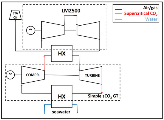
Figure 1.
Layout 1, simple sCO2 GT as WHR system.
Figure 2 reports a recuperated Brayton cycle (layout 2), in which part of the heat available at the turbine outlet is used to heat the gas leaving the compressor, to increase the global efficiency of the entire system.
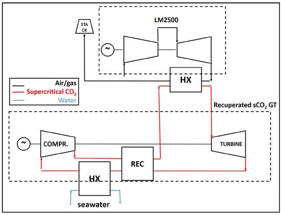
Figure 2.
Layout 2, recuperated sCO2 GT as WHR system.
The third scheme, shown in Figure 3, is a preheated and recuperated one. The additional heat exchanger can be useful to increase the thermal power addressed to the bottoming cycle and to reduce the exhaust gas temperature, with the stack temperature limited to 100 °C. In this way, it is possible to further heat of the working fluid before entering into the recuperator.
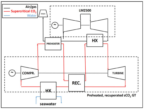
Figure 3.
Layout 3, preheated and recuperated sCO2 GT as WHR system.
In addition, a partial preheating can be considered by the splitting of the compressed working fluid between the recuperator and preheater. This scheme is depicted in Figure 4. In this layout, the sCO2 stream is separated at the compressor outlet in the following two different streams: the first enters in a low-temperature heater while the second goes to a recuperator. Then, the two streams enter together in a high-temperature heater [28].
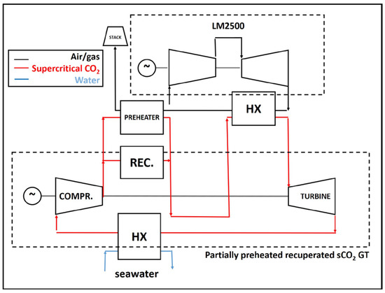
Figure 4.
Layout 4, partially preheated, recuperated cycle as WHR system.
The fifth sCO2 GT layout is reported in Figure 5 and regards the dual heated cascade cycle described in [28] and originally proposed in [29] as follows: a low-temperature turbine and a further heat exchanger are added with respect to the previous scheme. The layout provides two recuperators in series, namely, a low-temperature recuperator (LTR) and a high-temperature recuperator (HTR). The hot exhausts are used to heat the high-pressure sCO2 before entering in both the turbines.
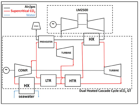
Figure 5.
Layout 5 dual-heated cascade cycle sCO2 GT as WHR system.
Supercritical CO2 exiting the turbine has a temperature that allows to consider a further waste heat recovery, and the latter scheme (Figure 6) regards a hybrid energy system in which a simple ORC system receives thermal power by the sCO2 Brayton cycle. The simple Rankine cycle has been individuated to limit the complexity of the layout and to consider that the sCO2 temperature at the compressor inlet should be close to the supercritical temperature. The cis-1,1,1,4,4,4-hexaflouro-2-butene, R1336mzz (Z), a hydrofluorolefin (HFO), is selected as working fluid of the ORC plant because of its low ODP and GWP values, low toxicity and flammability and good thermodynamic properties [30], as reported in Table 1, in which A1 denotes that R1336mzz (Z) is low toxicity (A) and presents no flame propagation (1) when tested as per the standard.
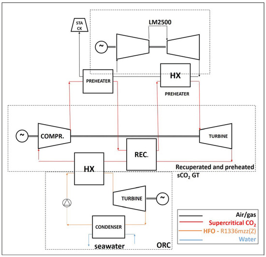
Figure 6.
Layout 6, Organic Rankine Cycle coupled to the preheated and recuperated sCO2 Brayton cycle.

Table 1.
R1336mzz (Z) thermo-physical properties.
3. Integrated Energy System Modeling and Validation
The steady-state behavior of the hybrid energy system is simulated using the commercial software Thermoflex of the Thermoflow suite [31], which enables the REFPROP–NIST property function for the gas stream to be used as required [32]. Thermoflex is a thermodynamic modeling software based on mass and energy balancing, and its database offers several modules and subsystems, which can be used as a black box to build complex energy system layouts.
The software allows the simulation of both design and off-design conditions. In this study, Thermoflex has been used in “thermodynamic design” conditions as follows: the software solves energy and mass balances to evaluate the thermodynamic performance. The main gas turbine has been modeled using a black-box approach, considering that the software embedded a wide commercial gas turbine library for design data and part load performance maps. The bottoming cycles have been modeled considering and connecting each single component (e.g., compressor, pump, heat exchanger, turbine, condenser) with the others. Some characteristic parameters (e.g., efficiency, pressure losses, thermal losses) have been taken by the literature. The software allows the use of control loops and to carry out parametric analysis.
The ideal gas equation of state (EoS) is not the most suitable in the case of carbon dioxide in supercritical conditions. To this aim, commercial codes such as Aspen Plus or Ebsilon Professional allow the selection of another, more suitable, equation of state such as the Peng-Robinson EoS [33] or the Lee–Kesler–Plöcker EoS [34]. Thermoflex, instead, allows us to use the REFPROP program, distributed through the Standard Reference Data program of NIST, which provides thermophysical properties of pure fluids and mixtures over a wide range of fluid conditions, including liquid, gas, and supercritical phases. The NIST REFPROP database provides the most accurate thermophysical property models for a variety of industrially important fluids and fluid mixtures, including accepted standards [35]. White et al. [36] conducted a comparative study on the evaluation of property methods for model sCO2 power cycles, even if mainly focused on direct-fired cycles, as follows: they concluded that REFPROP is a good performing property method when the working fluid is pure carbon dioxide in supercritical conditions, as also highlighted in [37].
In recent years, Thermoflex has been used in various research papers on hybrid energy systems based on gas turbines (see ref. [38] as regards the numerical models used for the small-scale plants based on micro gas turbines) and has been used to simulate sCO2 power cycles both in case of direct or indirect fired cycles, e.g., in [27,39,40].
This study is addressed to compare the layouts in the case of full-load conditions, and all parameters characterizing each component are considered to be constant (e.g., efficiencies of the rotating components and the heat exchangers) and are defined by the literature.
The main gas turbine is the aero-derivative GE LM2500 [41], which is installed on many ships (e.g., the Italian Navy PPA offshore patrol ships [29] and the V/STOL aircraft carrier Cavour [42], the RMS Queen Mary 2 cruise ship [43] and Millennium class of Celebrity Cruises [44]). Thermoflex includes performance and exhaust data within its software library for several configurations of this gas turbine model [31]; that data have been used by the literature in simulations and model comparisons, e.g., in [45,46]. Table 2 shows the LM2500+ reference data at full load condition, as reported by Thermoflow. The declared maximum model error in the test range is >0.5% for power, exhaust temperature, and mass flow.
Table 2.
LM2500 reference data.
The version of the turbine, which has been chosen for the study, is the natural gas-fueled LM2500+ G4. This solution is actually provided mainly in the case of stationary applications, but it represents an emerging solution in the case of liquefied natural gas (LNG).
The identification of the design parameters of sCO2 gas turbines has to consider the lack of experimental information. The experimental data regarding mainly prototypes and several characteristic parameters (e.g., isentropic compressor efficiency) can strongly differ with respect to the values considered as references in the theoretical or numerical studies by the literature [47].
The parameters of the sCO2 power cycle and ORC system models are defined by data published in the literature and presented in Table 3.
Table 3.
sCO2 GT/ORC model parameters.
The isentropic efficiency range of the compressor usually varies between 76% [18] and 80% [20,48,49], while the turbine efficiency values are usually between 85% [49] and 90% [17]. These values are mainly used by the literature. Thermoflex uses the polytropic efficiency, and the compressor efficiency is set at 80%, while the turbine efficiency is set at 85% to consider the isentropic efficiency in the range of the values considered by the literature.
The pressure range of both sCO2 GT and ORC has been defined considering the values usually published in the literature. The sCO2 gas turbine has to operate with a minimum pressure greater than the critical pressure, which is close to 73.8 bar. The upper limit is often fixed at 300 bar [12,40]. Regarding the ORC, the pressure corresponding to a condensing temperature of 25 °C for the chosen working fluid is 0.8 bar, while the critical pressure is 29.4 bar, as shown in Table 1. In this way, the working fluid operates always in subcritical conditions.
Once the parameters of the turbomachinery have been fixed, the main issues concern the heat exchangers’ characterization. In fact, the recuperator has the fundamental role of recovering waste heat and increasing the system performance, but they also present several issues related to the supercritical conditions of the working fluid that cannot be ignored.
The design and, consequently, the modeling of heat exchangers represent a critical issue related to the study of this type of plant due to the significant variations of the thermodynamic properties of carbon dioxide in the proximity of the critical point. The issue regards mainly the recuperators since in both the high- and low-temperature lines, the fluid is in supercritical conditions, and the different heat capacities of sCO2, could lead to internal pinch-points near to zero. This problem mainly affects the low-temperature recuperators, while at high temperatures and pressures, the difference in the specific heat is not significant [16].
This issue has to be considered within the numerical modeling, and, among the others, the authors have followed the solution proposed by Scaccabarozzi et al. [50], modeling the recuperator as two heat exchangers in series. In this way, it is possible to limit the issues related to the internal pinch-point. The authors chose to fix in both the heat exchanger the temperature difference at the pinch point at 10 K.
The recuperative heat exchangers’ efficiencies vary in the literature between 85% and 95%. In the numerical simulation, the heat exchanger efficiency has been fixed at 90%. An increase in the efficiency of the heat exchangers leads to an increase in the thermal efficiency of the system, but typically it corresponds to an increase in the size of the recuperator, and, consequently, its volume and weight. For example, in a recompression layout composed of two recuperators and a preheater, the increase in efficiency of the recuperators from 85% to 95% increases the total volume and weight by 1.5 m3 and 4.46 t [21].
3.1. sCO2 Gas Turbine Model Validation
In this section, a comparison between a model built in Thermoflex and the model based on an in-house numerical tool developed in Matlab [51] has been carried out. A numerical-experimental validation is not possible because of the lack of experimental data on this topic.
Considering the above-mentioned issues related to the presence of the recuperator, the comparison has been carried out on the simple regenerative cycle (layout no. 2).
To obtain a comparison, the boundary conditions and the characteristic parameters of each component have been set by [51].
The compressor and turbine efficiencies are 80% and 85%, respectively. The setting parameters of the main heat exchanger and of the recuperator are shown in Table 4. The comparison has been carried out considering that the heat exchanger has to operate with a fixed sCO2 stream exit temperature of 391.8 K since the heat exchanger efficiency is not performed.
Table 4.
Characteristic parameters of the model used for the validation.
Results of the comparison have been reported in Table 5. It is clear that the differences are related to the different modeling approach, mainly regarding the heat exchangers. The net power shown in Table 5 is defined as the difference between turbine and compressor power.
Table 5.
Model comparison with Ref. [51].
The variations in terms of power can be considered acceptable since it is a comparison between two different zero-dimensional thermodynamic models. To obtain more conservative results, the pressure and thermal losses at the heat exchangers have been set greater with respect to those chosen in this section as follows: the normalized heat loss is equal to 5.73%, while the ∆p/pin has been set at 1.05% and 2.77% respectively for the cold and hot side. The temperature difference at the pinch point has been set at 10 K.
3.2. Identification of the Mass Flow Rate of Each Layout
After setting the model parameters, the working fluid mass flow has been identified through a parametric analysis in which the sCO2 mass flow has been varied in a wide range, between 60 and 130 kg/s, in order to identify the value able to maximize the net power. In all the cases, a control loop has been used to identify the coolant mass flow rate to guarantee a supercritical carbon dioxide compressor inlet temperature of 32 °C. As shown in Figure 7, the results of the parametric analysis highlighted that the working fluid mass flow to maximize the net power varies from 64 kg/s for the simple cycle (layout 1) to 118 kg/s for the dual heated cascade cycle scheme (layout 5).
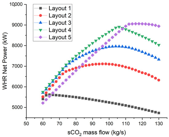
Figure 7.
WHR net power variation with sCO2 mass flow.
4. Energetic and Exergetic Analysis
The net power of the energy system considers the mechanical and electrical losses and the power consumption of the auxiliaries. is the net power of LM2500 GT, while and are the net power of the bottoming systems, defined as the difference between the power obtained by the turbine and the power consumed by the compressor and/or pumps.
The global efficiency of the hybrid system is defined in Equation (1), while the efficiency of the waste heat recovery is defined in Equation (2) as the ratio between the net power of the bottoming cycles and the maximum value of the thermal power available at the exhaust gases as follows:
where is the difference between enthalpies at the inlet of the heat exchanger and the limit value at the stack, corresponding to a stack temperature of 100 °C.
The exergy in input to the waste heat recovery system is the exergy transferred to supercritical carbon dioxide from the exhausts of the gas turbine and is equal to , considering the ambient temperature as the reference condition (T0 = 288.15 K).
The exergetic efficiency is reported in Equation (3).
Figure 8 compares the net power of the hybrid schemes analyzed, highlighting the contribution of the WHR system. The introduction of the preheater leads to a slight reduction in the main gas turbine power because of the backpressure at the exhaust. The increase in available power, with respect to the referring value of 32,686 kW shown in Table 1, ranges between 17% and 29% without any additional fuel. However, only for layout 1, this increase remains below 22%. The overall net efficiency increases to about 45% in the case of the Simple WHR scheme and up to 49% in the hybrid scheme with ORC and sCO2 GT (Figure 9), with an increase in the overall efficiency between 18% and 30%.
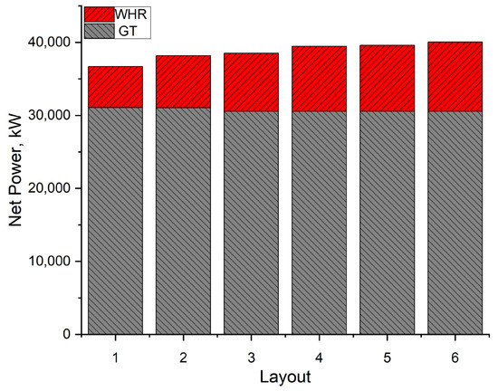
Figure 8.
Net power variation with WHR layout.
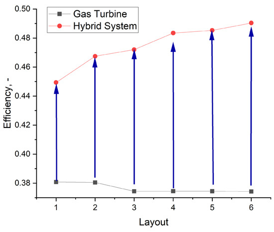
Figure 9.
Global efficiency variation with WHR layout.
Figure 10 shows the electrical efficiency and the exergetic efficiency of the bottoming system. All the chosen layouts ensure a satisfactory efficiency, also considering the simplicity of the first cases. At the same time, the exergetic efficiency highlights a good waste heat recovery from the exhausts of the gas turbine.
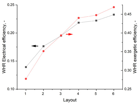
Figure 10.
WHR electrical (square) and exergetic efficiencies (circles).
A secondary effect of WHR is the reduction of the exhaust temperature to values between 200 °C and 100 °C with respect to the LM2500+ turbine outlet temperature of 511 °C (Figure 8).
Figure 11 also shows that at the end of the bottoming cycle, the relatively high temperature of sCO2 and, consequently, the available residual heat allows us to consider the introduction of a further bottoming cycle. ORC systems, for instance, are suitable for heat recovery from medium-low enthalpy sources. Case 6 is an example of this possibility.
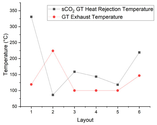
Figure 11.
Temp. of sCO2 at cold sink HX (square) and GT exhaust temperature (circles).
The introduction of WHR implies a significant increase in the global efficiency of the energy system. WHR benefits in marine applications are clearly stated, also considering the most recent IMO index for assessing the energy efficiency and environmental impact of ships, the EEXI index [3]. In fact, this index is defined as follows [52]:
where is the power of main engines in kW, SFC the specific fuel consumption for different loads at ship, measured in tfuel/kW, Vref is the speed of the sheep at 75% MCR corresponding to the capacity; CF-Capacity (Deadweight for container vessels, 70% of deadweight) and are correction factors. The introduction of WHR leads to an increase both in and SFC.
However, such schemes introduce complex additional components in the energy scheme, and this may lead to some issues related to plant engineering, maintenance, and management costs. Thus, in order to evaluate the real cost/benefits of the adopted scheme, the analysis of the performance of such systems becomes relevant as the operating conditions vary.
It Is well known that any energy system is affected by ambient conditions. In particular, gas turbines are sensitive to variations in ambient temperature, while any closed-loop thermodynamic cycle, as in the case of sCO2 and ORC, strongly depends on the temperature of both hot and cold heat sources. In the case of marine applications, seawater is the cold sink whose temperature can vary significantly according to the route followed by the ship. Thus, in the next section, the influence of seawater temperature on the overall energy system performance is analyzed.
5. Effects of Seawater Temperature on Overall Performance
The seawater temperature can be locally considered constant, but container ships, bulk carriers, or oil tankers need to cross throughout different seas/oceans and seasons also in a single travel. Thus, the effects of seawater temperature on the overall performance of the energy system are important parameters in the evaluation of the WHR benefits that cannot be neglected, being that seawater is the cold sink of the cycle. In the specific literature, the water temperature close to the sea/ocean surface, considering also the first 20 m of depth, is called sea surface temperature (SST). SST evolution is an essential climate variable, which is fundamental in any climate regulation analysis [53].
For example, ships long beyond 300 m have to pass the Horne Cape to reach the Pacific Ocean starting from the Atlantic one, since the constraints on the Panama Canal, thus passing, in May, from 20 to 38 °C of the US east coast to 10–18 °C of the US west coast, through the 4–8 °C of the Horne Cape [54]. At the same time, several ships from the East Coast of the US and Canada usually reach China or the Far East passing through both the Mediterranean Sea [53,54] and the Red Sea [53,54,55]. The difference in annual mean SST between the Mediterranean Sea and the Red Sea is about 8 °C but can be greater as follows: between 14.9 °C and 25.1 °C in winter, 18.2 °C and 27.8 °C in spring, 25.1 °C and 30.3 °C in summer and 20.3 °C and 28.3 °C in autumn.
A parametric analysis by varying seawater temperature has been carried out, in order to consider this aspect. In the analysis, even if ambient conditions influence the main gas turbine operation and, consequently, the amount of thermal power which is available for the bottoming cycle, the ambient air temperature has been considered constant. This is for both the sake of simplicity and to highlight the effect of seawater temperature variations.
In scheme 6, in the first analysis, the design condensing pressure of the ORC has been fixed at 0.8 bar, as in the previous simulations. It is clear that the condensation pressure and, consequently, the temperature have to be defined considering the cold heat source temperature.
The results of the parametric analysis are shown in Figure 12, where it is reported the sCO2 gas turbine net power variation with sea surface temperature.
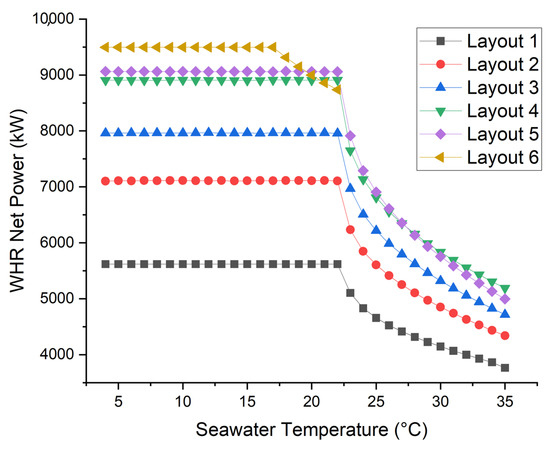
Figure 12.
sCO2 GT net power variation with seawater temperature.
The effect of SST on the bottoming cycle is relevant for high seawater temperatures, and it is due to the peculiar behavior of carbon dioxide in proximity to its supercritical temperature at 31 °C. For sCO2 temperature close to this value, the cycle presents its best performance, while higher seawater temperatures lead to higher sCO2 temperature and, consequently, a different behavior in correspondence of the compressor. The WHR system continues to operate fairly, but the power and efficiency gain results are reduced.
As expected, the effect is more relevant for the following sixth case: the condensation temperature of the organic working fluid in the analyzed pressure conditions is within the range of variability of the seaside temperature and, in these conditions, the WHR system could operate only in a reduced range of temperatures. Thus, the use of the latter layout is possible only with a redesign of the pressure levels of the ORC system, and a further parametric analysis has been carried out to consider this point by varying the condensing pressure of the bottoming cycle.
In the analyzed temperature range of the cold source (4–35 °C), the lowest pressure at which the ORC can work in all the conditions is 1.3 bar. The increasing of the minimum pressure of the ORC leads to a decrease in its net power and, consequently, of the WHR net power. As shown in Figure 13, at 1.3 bar, the WHR net power is about 20% below the reference case, but the system can operate also in case of high seawater temperature. Seeing Figure 12 and Figure 13, layout 5 appears to be the most suitable since it guarantees the highest net power in the wider SST temperature range.
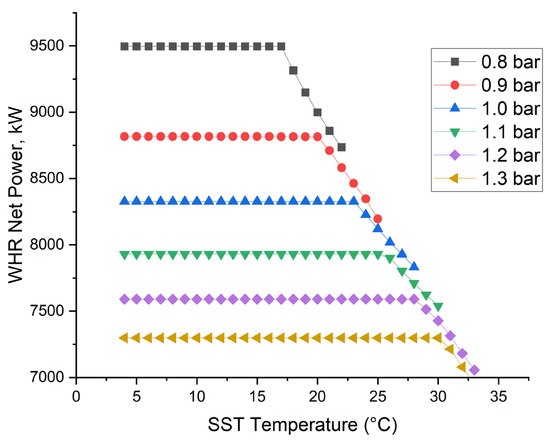
Figure 13.
layout 6: WHR net power variation with seawater temperature and condensing pressure.
6. Conclusions
The paper investigates the effects on the performance of waste heat recovery in marine applications when the main engine is a gas turbine, and the bottoming cycle is a supercritical CO2 closed Brayton cycle. The subject of study is the GE LM2500+. Six different configurations have been evaluated to individuate the best compromise between the increase in power and efficiency and the increase in complexity and weight of the hybrid energy system. Five of these consider sCO2 gas turbine layouts, from the simplest with just two heat exchangers, to a complex system with five heat exchangers and an additional turbine. Finally, a hybrid system in which an ORC is also present is discussed.
Results of numerical simulations showed that depending on the layout of the WHR, the increase in available power is between 17% and 29%. The overall net efficiency increases to about 45% in the case of the Simple WHR scheme and up to nearly 49% in the hybrid scheme with ORC and sCO2.
The effect of seawater temperature on the WHR performance has been also analyzed. In the case of seawater temperatures greater than 30 °C, the efficiency of supercritical CO2 gas turbines decreases by more than 30%, while the efficiency of the cascade layout sCO2 GT-ORC is also limited by the higher condensing pressure levels.
Author Contributions
Conceptualization, F.R. and P.M.; methodology, F.R.; writing—original draft, F.R.; writing—review and editing, R.C. and P.M. All authors have read and agreed to the published version of the manuscript.
Funding
This research received no external funding.
Data Availability Statement
Data sharing not applicable.
Conflicts of Interest
The authors declare no conflict of interest.
Nomenclature
| COGAS | Combined Gas Turbine and Steam turbine |
| COGES | Combined Gas Turbine Electric and Steam |
| EEXI | Energy Efficiency Existing Ship Index |
| EoS | Equation of State |
| HFO | Hydrofluorolefin |
| HX | Heat Exchanger |
| HTR | High Temperature Recuperator |
| GHG | Greenhouse Gas |
| GWP | Global Warming Potential |
| GT | Gas Turbine |
| IMO | International Maritime Organization |
| LNG | Liquefied Natural Gas |
| LTR | Low Temperature Recuperator |
| MARPOL | “MARitime POLlution”, MARPOL 73/78, International Convention for the Prevention of Pollution from Ships |
| ODP | Ozone Depletion Potential |
| ORC | Organic Rankine Cycle |
| sCO2 | Supercritical Carbon Dioxide |
| SFC | Specific Fuel Consumption |
| SST | Sea Surface Temperature |
| TIT | Turbine Inlet Temperature |
| TOT | Turbine Outlet Temperature |
| WHR | Waste Heat Recovery |
| WHRS | Waste Heat Recovery System |
| Greek | |
| Difference of Temperature [K] | |
| ε | Heat Exchanger Efficiency |
| η | Efficiency |
| ξ | Exergy |
| Subscripts | |
| Ex | Exergy |
| Max | Maximum |
| Pp | Pinch Point |
| In | Inlet |
References
- IMO. Cutting GHG Emissions from Shipping—10 Years of Mandatory Rules. 2021. Available online: https://www.imo.org/en/MediaCentre/PressBriefings/pages/DecadeOfGHGAction.aspx (accessed on 25 May 2022).
- Zhu, S.; Zhang, K.; Deng, K. A review of waste heat recovery from the marine engine with highly efficient bottoming power cycles. Renew. Sustain. Energy Rev. 2020, 120, 109611. [Google Scholar] [CrossRef]
- IMO. EEXI and CII—Ship Carbon Intensity and Rating System. Available online: https://www.imo.org/en/MediaCentre/HotTopics/Pages/EEXI-CII-FAQ.aspx (accessed on 13 May 2023).
- Sing, D.V.; Pedersen, E. A review of waste heat recovery technologies for maritime applications. Energy Convers. Manag. 2016, 111, 315–328. [Google Scholar] [CrossRef]
- Haglind, F. A review on the use of gas and steam turbine combined cycles as prime movers for large ships. Part II: Previous work and implications. Energy Convers. Manag. 2018, 49, 3468–3475. [Google Scholar] [CrossRef]
- Altosole, M.; Benvenuto, G.; Campora, U.; Laviola, M.; Trucco, A. Waste Heat Recovery from Marine Gas Turbines and Diesel Engines. Energies 2017, 10, 718. [Google Scholar] [CrossRef]
- Haglind, F. A review on the use of gas and steam turbine combined cycles as prime movers for large ships. Part I: Background and design. Energy Convers. Manag. 2008, 49, 3458–3467. [Google Scholar] [CrossRef]
- Badeer, G.H. GE Aeroderivative Gas Turbines-Design and Operating Features; GER-3695E; GE Power Systems: Evendale, OH, USA, 2000. [Google Scholar]
- Wang, Z.; Jiang, Y.; Han, F.; Yu, S.; Li, W.; Ji, Y.; Cai, W. A thermodynamic configuration method of combined supercritical CO2 power system for marine engine waste heat recovery based on recuperative effects. Appl. Therm. Eng. 2022, 200, 117645. [Google Scholar] [CrossRef]
- Marchionni, M.; Bianchi, G.; Tassou, S.A. Review of supercritical carbon dioxide (sCO2) technologies for high-grade waste heat to power conversion. SN Appl. Sci. 2020, 2, 611. [Google Scholar] [CrossRef]
- Ahn, Y.; Bae, S.J.; Kim, M.; Cho, S.K.; Baik, S.; Lee, J.I.; Cha, J.E. Review of supercritical CO2 power cycle technology and current status of research and development. Nucl. Eng. Technol. 2015, 47, 647–661. [Google Scholar] [CrossRef]
- Crespi, F.; Gavagnin, G.; Sanchez, D.; Martinez, G.S. Supercritical carbon dioxide cycles for power generation: A review. Appl. Energy 2017, 195, 152–183. [Google Scholar] [CrossRef]
- Xu, J.; Liu, C.; Sun, E.; Xie, J.; Li, M.; Yang, Y.; Liu, J. Perspective of S−CO2 power cycles. Energy 2019, 186, 115831. [Google Scholar] [CrossRef]
- Feher, E.G. The Supercritical Thermodynamic Power Cycle. Energy Convers. 1968, 8, 85–90. [Google Scholar] [CrossRef]
- Angelino, G. Carbon dioxide condensation cycles for power production. J. Eng. Gas. Turbines Power 1968, 90, 287–295. [Google Scholar] [CrossRef]
- Gotelip, T.; Gampe, U.; Glos, S. Optimization strategies of different SCO2 architectures for gas turbine bottoming cycle applications. Energy 2022, 250, 123734. [Google Scholar] [CrossRef]
- Wright, S.A.; Davidson, C.S.; Scammel, W.O. Thermo-Economic Analysis of Four sCO2 Waste Heat Recovery Power Systems. In Proceedings of the 5th Int Symp—Supercrit CO2 Power Cycles, San Antonio, TX, USA, 28–31 March 2016; pp. 1–16. [Google Scholar]
- Sakalis, G.N. Design and partial load operation optimization of integrated ship energy system based on supercritical CO2 waste heat recovery cycle. Sustain. Energy Technol. Assess. 2022, 51, 101965. [Google Scholar] [CrossRef]
- Hou, S.; Zhang, F.; Yu, L.; Cao, S.; Zhou, Y.; Wu, Y.; Hou, L. Optimization of a combined cooling, heating and power system using CO2 as main working fluid driven by gas turbine waste heat. Energy Convers. Manag. 2018, 178, 235–249. [Google Scholar] [CrossRef]
- Hou, S.; Wu, Y.; Zhou, Y.; Yu, L. Performance analysis of the combined supercritical CO2 recompression and regenerative cycle used in waste heat recovery of marine gas turbine. Energy Convers. Manag. 2017, 151, 73–85. [Google Scholar] [CrossRef]
- Du, Y.; Hu, C.; Wang, H.; Dong, W. Size optimization of heat exchanger and thermoeconomic assessment for supercritical CO2 recompression Brayton cycle applied in marine. Energy 2021, 239, 122306. [Google Scholar] [CrossRef]
- Pan, P.; Yuan, C.; Sun, Y.; Yan, X.; Lu, M.; Bucknall, R. Thermo-economic analysis and multi-objective optimization of S-CO2 Brayton cycle waste heat recovery system for an ocean-going 9000 TEU container ship. Energy Convers. Manag. 2020, 221, 113077. [Google Scholar] [CrossRef]
- Hu, K.; Liu, X.; Chen, Y.; He, D. Influence of marine conditions on thermal efficiency of SCO2 Brayton cycle for waste heat recovery. Appl. Therm. Eng. 2023, 227, 120391. [Google Scholar] [CrossRef]
- Guo, J.; Du, J.; Li, M.; Zhang, Z. Performance study of a supercritical CO2 Brayton cycle coupled with a compressed CO2 energy storage system for waste heat recovery of ship gas turbines under variable load conditions. Sustain. Energy Fuels 2022, 6, 5557. [Google Scholar] [CrossRef]
- Sahoo, A.; Sanjay, R.; Jain, M. Analysis of Recompression-Regeneration sCO2 Combined Cycle Utilizing Marine Gas Turbine Exhaust Heat: Effect of Operating Parameters; SAE Technical Paper 2022-01-5059; SAE International: Warrendale, PA, USA, 2022. [Google Scholar] [CrossRef]
- Chacartegui, R.; Muñoz de Escalona, J.M.; Sánchez, D.; Monje, B.; Sánchez, T. Alternative cycles based on carbon dioxide for central receiver solar power plants. Appl. Therm. Eng. 2011, 31, 872–879. [Google Scholar] [CrossRef]
- Reale, F.; Iannotta, V.; Tuccillo, R. Numerical Study of a Micro Gas Turbine Integrated with a Supercritical CO2 Brayton Cycle Turbine. In Proceedings of the ASME Turbo Expo 2018: Power for Land, Sea and Air; Paper no. GT2018-76656, Oslo, Norway, 11–15 June 2018. [Google Scholar] [CrossRef]
- Bonalumi, D.; Giuffrida, A.; Sicali, F. A case study of cascade supercritical CO2 power cycle for waste heat recovery from a small gas turbine. Energy Convers. Manag. X 2022, 14, 100212. [Google Scholar] [CrossRef]
- Kimzey, G. Development of a Brayton Bottoming Cycle Using Supercritical Carbon Dioxide as the Working Fluid; Electric Power Research Institute Report; University Turbine Systems Research Program: Palo Alto, CA, USA, 2012; pp. 1–31. [Google Scholar]
- Navarro-Esbrí, J.; Molés, F.; Peris, B.; Mota-Babiloni, A.; Kontomaris, K. Experimental study of an Organic Rankine Cycle with HFO-1336mzz-Z as a low global warming potential working fluid for micro-scale low temperature applications. Energy 2017, 133, 79–89. [Google Scholar] [CrossRef]
- Thermoflow. Thermoflex v. 30. Available online: www.thermoflow.com (accessed on 10 March 2023).
- Lemmon, E.W.; Bell, I.H.; Huber, M.L.; McLinden, M.O. NIST Standard Reference Database 23: Reference Fluid Thermodynamic and Transport Properties-REFPROP, Version 10.0; National Institute of Standards and Technology, Standard Reference Data Program: Gaithersburg, MD, USA, 2018. [Google Scholar]
- Peng, D.Y.; Robinson, D.B. A New Two-Constant Equation of State. Ind. Eng. Chem. Fundam. 1976, 15, 59–64. [Google Scholar] [CrossRef]
- Plocker, U.; Knapp, H.; Prausnitz, J. Calculation of High-Pressure Vapor-Liquid Equilibria from a Corresponding States Correlation with Emphasis on Asymmetric Mixtures. Ind. Eng. Chem. Process Des. Dev. 1978, 17, 324–332. [Google Scholar] [CrossRef]
- Reference Fluid Thermodynamic and Transport Properties Database (REFPROP). Available online: https://www.nist.gov/programs-projects/reference-fluid-thermodynamic-and-transport-properties-database-refprop (accessed on 20 May 2023).
- White, C.W.; Weiland, N.T. Evaluation of Property Methods for Modeling Direct-Supercritical CO2 Power Cycles. J. Eng. Gas Turbines Power 2018, 140, 011701. [Google Scholar] [CrossRef]
- Zhao, Q.; Mecheri, M.; Neveux, T.; Privat, R.; Jaubert, J.-N. 2016 Thermodynamic Model Investigation for Supercritical CO2 Brayton Cycle for Coal-Fired Power Plant Application. In Proceedings of the Fifth International Supercritical CO2 Power Cycles Symposium, San Antonio, TX, USA, 29–31 March 2016; Paper No. 93. [Google Scholar]
- Reale, F.; Sannino, R. Numerical Modeling of Energy Systems Based on Micro Gas Turbine: A Review. Energies 2022, 15, 900. [Google Scholar] [CrossRef]
- Colleoni, L.; Sindoni, A.; Ravelli, S. Comprehensive Thermodynamic Evaluation of the Natural Gas-Fired Allam Cycle at Full Load. Energies 2023, 16, 2597. [Google Scholar] [CrossRef]
- Ancona, M.A.; Bianchi, M.; Branchini, L.; De Pascale, A.; Melino, F.; Peretto, A.; Torricelli, N. Systematic Comparison of ORC and s-CO2 Combined Heat and Power Plants for Energy Harvesting in Industrial Gas Turbines. Energies 2021, 14, 3402. [Google Scholar] [CrossRef]
- GE Aerospace Website. Available online: https://www.geaerospace.com/sites/default/files/lm2500plusg4-ppa-case-study.pdf (accessed on 14 March 2023).
- Fincantieri Website. Available online: https://www.fincantieri.com/it/prodotti-servizi/navi-militari/classe-cavour/ (accessed on 14 March 2023).
- GE Aerospace Website. Available online: https://www.geaerospace.com/press-release/marine-industrial-engines/ges-lm2500-gas-turbines-power-queen-mary-2-worlds-largest (accessed on 14 March 2023).
- GE Aerospace Website. Available online: https://www.geaerospace.com/press-release/marine-industrial-engines/ges-gas-turbine-engines-celebrity-cruises-millennium-log (accessed on 14 March 2023).
- De Andrade Cruz, M.; de Queiroz Fernandes Araújo, O.; de Medeiros, J.L. Deep seawater intake for primary cooling in tropical offshore processing of natural gas with high carbon dioxide content: Energy, emissions and economic assessments. J. Nat. Gas Sci. Eng. 2018, 56, 193–211. [Google Scholar] [CrossRef]
- Reis, M.M.L.; Gallo, W.L.R. Study of waste heat recovery potential and optimization of the power production by an organic Rankine cycle in an FPSO unit. Energy Convers. Manag. 2018, 157, 409–422. [Google Scholar] [CrossRef]
- Vidoza, J.A.; Andreasen, J.G.; Haglind, F.; dos Reis, M.M.L.; Gallo, W. Design and optimization of power hubs for Brazilian off-shore oil production units. Energy 2019, 176, 656–666. [Google Scholar] [CrossRef]
- Martin, T.; White, M.T.; Bianchi, G.; Chai, L.; Tassou, S.A.; Sayma, A.I. Review of supercritical CO2 technologies and systems for power generation. Appl. Therm. Eng. 2021, 185, 1164447. [Google Scholar]
- Li, B.; Wang, S.S.; Zu, Y.; Song, L. Study on the off-design performance of supercritical carbon dioxide power cycle for waste heat recovery of gas turbine. Energy Convers. Manag. 2021, 233, 113890. [Google Scholar] [CrossRef]
- Scaccabarozzi, R.; Gatti, M.; Martelli, E. Thermodynamic Analysis and Numerical Optimization of the NET Power Oxy-Combustion Cycle. Appl. Energy 2016, 178, 505–526. [Google Scholar] [CrossRef]
- Alfani, D.; Binotti, M.; Macchi, E.; Silva, P.; Astolfi, M. sCO2 power plants for waste heat recovery: Design optimization and part-load operation strategies. Appl. Therm. Eng. 2021, 195, 117013. [Google Scholar] [CrossRef]
- Inanova, F. Analysis of the Specifics in Calculating the Index of Existing Marine Energy Efficiency EEXI in Force since 2023. In Proceedings of the 13th Electrical Engineering Faculty Conference, Varna, Bulgaria, 8–11 September 2021. [Google Scholar] [CrossRef]
- García-Monteiro, S.; Sobrino, J.A.; Julien, Y.; Sòria, G.; Skokovic, D. Surface Temperature trends in the Mediterranean Sea from MODIS data during years 2003–2019. Reg. Stud. Mar. Sci. 2022, 49, 102086. [Google Scholar] [CrossRef]
- OSPO NOAA. Sea Surface Temperature (SST) Contour Charts. Available online: https://www.ospo.noaa.gov/Products/ocean/sst/contour/ (accessed on 29 January 2023).
- Shaltout, M. Recent sea surface temperature trends and future scenarios for the Red Sea. Oceanologia 2019, 61, 484–504. [Google Scholar] [CrossRef]


Disclaimer/Publisher’s Note: The statements, opinions and data contained in all publications are solely those of the individual author(s) and contributor(s) and not of MDPI and/or the editor(s). MDPI and/or the editor(s) disclaim responsibility for any injury to people or property resulting from any ideas, methods, instructions or products referred to in the content. |
© 2023 by the authors. Licensee MDPI, Basel, Switzerland. This article is an open access article distributed under the terms and conditions of the Creative Commons Attribution (CC BY) license (https://creativecommons.org/licenses/by/4.0/).