Abstract
As the siting of wind turbines increasingly transitions from shallow water to offshore deep-water locations, improving the platform stability of floating offshore wind turbines is becoming a growing concern. By coupling a porous shell commonly used in traditional marine structures, with a FOWT (floating wind turbine platform), a new spar-buoy with a porous shell was designed. A numerical model investigating the coupling effect of the aero-hydro-mooring system is developed, and the results of the motion response are compared with the OC3-Hywind spar. The motion response of the two platforms was simulated in the time-domain with the incident wave period varied in the range of 5~22 s. The exciting wave force with added mass and radiation damping of the spar with the porous shell is compared with the OC3-Hywind spar. The results demonstrate that the motion response amplitude of the spar with the porous shell decreases in all three main motion freedoms (i.e., surge, heave and pitch, etc.), among which the heave motions are most significantly attenuated. The study shows that the coupling of porous shells with a floating platform to achieve the reduced motion responses is feasible and can be an innovative structure for the development of deep-sea offshore floating wind turbines.
1. Introduction
In recent decades, due to the problems of environmental pollution and the depletion of fossil energy sources, mankind has placed increasing emphasis on the development of clean energy sources. Wind energy is developing into one of the mainstream clean energy sources [1]. In the deep ocean, the wind energy density resource is greater and environmental impacts and community opposition can be mitigated. Thus, the deep ocean environment is the future direction of wind turbine development. In offshore locations, floating wind turbines are subject to more complex environmental conditions and are exposed to severe currents, waves and wind loads. These more complex working conditions may lead to greater motion responses and more severe damage to wind turbine blades [2,3]. The main focus of this paper is reducing the motion response of platform. By reducing these motion responses, damage to the component parts of the wind turbine may be mitigated. The large motion responses due to the cyclic loading on the platform structure tends to significantly decrease the fatigue design life of the structural system [4]. In addition, the coupled effect between the hydrodynamic and aerodynamic loads on the floating turbine can affect both the overall stability of the turbine and influence the power generation efficiency [5]. Currently, there is much ongoing research focused on reducing the motion response of offshore platforms by combining floating platforms with other attached structures such as heaving plates, tuned mass dampers and floating tube structures, etc. Lin et al. [6] designed a floating structure using deep draft floats. The inclusion of the deep draft floats had the advantageous effect to reduce the wave forces on the floating platform. According to the results, the new floating platform is able to avoid the main wave energy zone but has not been compared with similar existing platforms. Rao et al. [7] performed a 1:100 scale model experiment to investigate the heave damping and added mass of a classical spar with a heaving plate. They found that the heaving plates increase the damping and additional mass and reduces the kinematic response. Hegde et al. [8] computed the damping and added mass effects by tracking wind and wave attenuation using CFD methods and compared the results with experimental observations from a 1:100 model. They also investigated the effect of the heaving-plate diameter and the ratio of the heaving plate position and draft on damping and arrived at the optimum configuration. The addition of a heaving plate to the still surface had better effects in reducing the motion response. Yang et al. [9] installed two tuned mass dampers on the spar and nacelle of a floating offshore wind turbine (FOWT) to control the vibration response of the floating platform. Moreover, they developed an aero-hydro-servo-structure-tuned-mass-damper (TMD) coupled motion model. The stiffness and damping coefficients of the TMD were optimized. By studying the damping effect in the free decay state and under wind and wave loads, it was found that the installation of the TMD reduces the motion response of the platform.
In addition to the above studies on reducing the motion response of FOWTs, porous structures are often used in the marine industry to dissipate energy and reduce the kinematic response of the structure. Porous structures are commonly employed in fixed and floating breakwaters [10,11], and are used to augment the motion damping of marine structures [12,13,14,15,16]. Mackay et al. [17] investigated the use of porous materials for reducing loads on fixed and offshore structures and damping wave-induced motions of floating structures by means of the boundary element numerical method (BEM) and two physical experimental models. They confirmed that porous structures have good potential to effectuate load reduction and motion damping on floating structures. Saha et al. [18] investigated the scattering phenomena in water waves from a porous composite cylinder with an annular porous cap. They found that the wave force on an inner concentric column diminished when the value of the porous parameter was low, and that the wave force on the outer wall was larger when the value of the porous parameter was higher. Many previous research studies ignore the influence of the aerodynamic component when they consider the motion response of the floating platform. For example, Ding et al. [19] used the equivalent-effectiveness model to study the motion attenuation of a pendulum. By ignoring the influence of the aerodynamic component or by applying these idealized models, it is difficult to effectively analyze the influence of the coupling effect between the platform and the turbine. Therefore, the aero-hydro-mooring coupling method is adopted in this research to study the motion response of the floating turbine.
Based on the review of the above studies, the concept of increasing the damping and added mass of a spar structure by combining a porous shell with a floating spar platform was generated. The aim of this study is to propose a novel structure to reduce the motion response of the FOWT platform. In this paper, the motion responses of the porous structure coupled with the floating platform using the aero-hydro-mooring model are investigated. The motion response of a spar model with an integrated porous shell is compared with the motion response of a spar without the porous shell. The reduction in the motion response is analyzed by investigating the effects of variation in the exciting wave force, added mass and radiation damping, etc. The remainder of the manuscript is structured as follows. Section 2 presents the model setup and the coupled aero-hydro-mooring framework. Section 3 describes the model validation and Section 4 presents the research results. Finally, the research conclusions are summarized in Section 5.
2. Model Description
2.1. Model Setup
The schematic diagram of the FOWT model with the porous shell is shown in Figure 1. The OC3-Hywind FOWT structure is selected in this study. The porous shell is integrated with the vertical spar at the incident wave height region. The new floating platform is an innovation based on the traditional spar platform OC3-Hywind spar. The difference is the addition of a porous cylindrical shell near the still surface of the OC3-Hywind spar. The specifications of the model setup are as follows: the porous cylinder outer diameter D3 = 9.4 m, the inner diameter D4 = 8.8 m, the wall thickness dP = 0.3 m and the porosity τ = 0.3. The openings in the porous cylinder are circular and arranged on a regular square grid (The radius of the openings, r is obtained from the porosity formula ). By taking into account the actual sea-state working conditions and the wave heights, the porous cylindrical shell is placed at a water depth of 6 m with the top of the shell at 2 m above the still water surface. There are no holes in the porous shell section above the still water surface, the shell is only porous below the still water surface. The 306 mm diameter holes are spaced according to a regular arrangement at 500 mm centers. The mass and inertia of the platform itself are aligned by adjusting the mass of the ballast. In Figure 2, we present a front view and top view of the structure, and a schematic diagram of the porous shell. The porous cylinder is coupled to the spar shell at its top. It is envisaged that the porous shell can be connected to the spar by means of a welded connection.
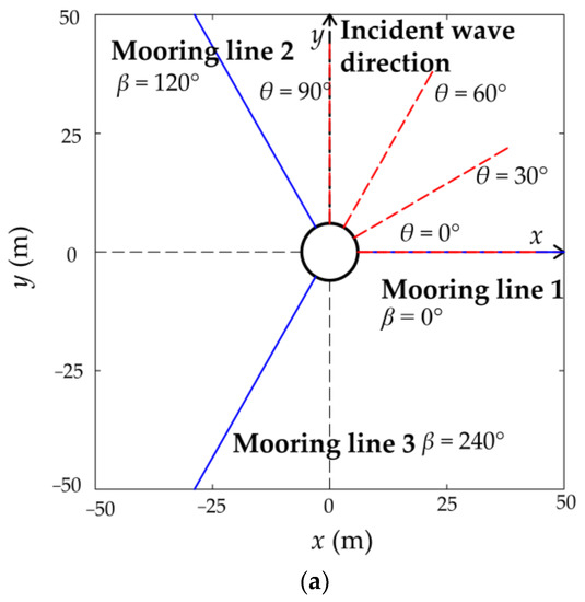
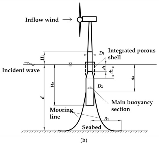
Figure 1.
(a) Incident wave loading specifications. (b) Spar structure with integrated porous shell. (θ is the incident angle of wave, β is the angle of mooring line.).
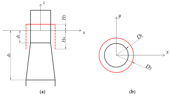
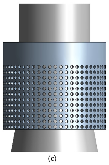
Figure 2.
The specific dimensions of the integrated porous shell. (a) Front view. (b) Top view. (c) Schematic diagram of the porous shell.
To dissipate wave energy and reduce motion, the use of a porous on traditional marine structure has been extensively investigated in previous works with advantageous effects but has yet to be developed and refined for use in FOWT platform. Excessive pitch and heave motions of spar platforms are prone to affect the stability and safety of the platform’s operation. In this work, a new FOWT incorporating a porous shell is proposed and studied. The results are compared with the conventional OC3-Hywind spar. To facilitate subsequent model validation, the upper wind turbine model is selected as the NREL-5MW model for subsequent validation.
The structural parameters of the OC3-Hywind spar floating platform are presented in Table 1 and the mooring system specifications are given in Table 2 [20]. Both floating platforms are equipped with the NREL 5MW model wind turbines [21]. Table 3 presents the porous shell specifications.

Table 1.
Structural parameters of OC3-Hywind spar floating platform.
Table 2.
Mooring system specifications.
Table 3.
Porous shell specifications.
2.2. Load Coupling Framework
The OC3-Hywind spar supports a NREL 5MW model wind turbine. The rotation of the turbine blades induces large thrust forces and overturning moments during the operation of the turbine, which influences the stability and working performance of the FOWT. Therefore, a detailed coupled analysis on the various component loads applied to the FOWT spar is necessary. The load category and the coupling process are described hereafter.
2.2.1. Aerodynamic Load
To simulate the actual wind conditions at sea, the calculation of the aerodynamic loading needs to take into account the effect of wind loads. The blade element theory and momentum theory are employed for the calculation of aerodynamic loads [22]. According to blade element theory, it is assumed that each blade element of the turbine is independent and has no influence on the other blade elements. Then, there are two components of aerodynamic loading acting on each blade unit. These are the lift forces on the airfoil and the drag forces on the airfoil. The rotation of the turbine blades applies the thrust and torque loading on the FOWT spar.
Thrust can be calculated according to,
Torque can be calculated from,
where B is the number of blades, is the density of air, V is the relative velocity of the blade, c is the chord length of the segment of the blade airfoil element under consideration, is the lift coefficient, is the aerodynamic drag coefficient, φ is the angle of inflow and r is the radius of the blade. The calculated thrust and torque forces on the individual blade elements are integrated along the blade length to obtain the aerodynamic load of the entire blade. In this study a wind speed of 11.4 m/s was considered.
By using Equations (1) and (2), we can obtain the aerodynamic load () on the FOWT in working conditions.
2.2.2. Hydrodynamic Load
The Morrison formulation and Potential Flow theory are commonly used in hydrodynamic load calculations for floating platforms [23]. For small diameter components in the flow field, where the characteristic diameter is less than 0.2 times the incident wavelength, the influence of the structure on the surrounding flow field is negligible, and only the viscosity effect and added mass effect are considered. In this study, the Morrison formulation is used to calculate the hydrodynamic force on the small diameter components. Then the force on the cross-section of the spar structural member is calculated according to the following equation:
where is the hydrodynamic drag coefficient. D is the characteristic drag diameter. is the lateral velocity of the fluid particles. is the lateral velocity of the structure. ρ is the seawater density with a value of 1.025 g/cm3. is the inertia coefficient. A is the cross-sectional area of the component under consideration and L is the length of the structure.
For large-diameter components whose diameter is greater than 0.2 times the incident wavelength, the presence of the structure affects the surrounding flow field and wave diffraction effects must be considered. In this study, the linear potential flow theory is used to calculate the force on the large-diameter components. This method assumes that the body of water is an ideal fluid which is incompressible, inviscid and irrotational. The fluid velocity potential around the floating body satisfies the Laplace equation,
The velocity potential also needs to satisfy the free surface and body surface conditions:
The radiation condition is the following:
where is incident wave velocity potential. g is gravitational acceleration. t is time. d is the water depth. n is the unit normal vector of FOWT foundation pointing inward and Γ is the surface of the porous shell. The specific wave conditions considered can be found in Table 5.
Using Equations (3)–(8), we can calculate the hydrodynamic loads () on the various parts of the FOWT under wave.
2.2.3. Mooring Load
A multi-segmented, quasi-static (MSQS) cable system [24] model is used to calculate the mooring load. The MSQS method is based on the classical suspension chain line theory. It ignores the weight of the mooring cable, the hydrodynamic damping and other dynamic response characteristics. The Newton–Raphson iterative method is used to solve for the mooring chain tension.
2.2.4. Load Coupling Procedure
The AeroDyn module is used to calculate the aerodynamic load component. The hydrodynamic loads are simultaneously calculated by ANSTS AQWATM. The mooring cable tension is computed using the MAP++ module based on the MSQS method, and finally the coupling procedure and integrated load implementation analysis is performed using OpenFAST©.
The equation of motion can be expressed as:
where is the inertial mass matrix, which includes the added mass component when the hydrodynamic load is applied to the floating foundation. The added mass is denoted as and the radiation damping is denoted as Bij. , and x are the acceleration, velocity and displacement vectors in the component directions of six degree of freedom of the floating wind turbine, respectively. X, Y, Z, RX, RY and RZ are used to represent the displacement in the surge, sway, heave, roll, pitch and yaw, motions, respectively. u is the system control input. t is time and Fi is the associated force function on the degree of freedom.
The load on a floating wind turbine can be expressed as the following:
where is generalized aerodynamic loads, is the generalized mooring load, is generalized hydrodynamic loads.
Thus, the complete modeling process for solving the motion Equation (9) is presented in Figure 3.
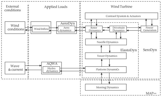
Figure 3.
Flow chart of coupled dynamic analysis of AQWA-FAST.
2.2.5. Motion Response of Floating Platform Coupled with Porous Structure
The model hydrodynamic parameters in the frequency domain are calculated using the Hydrodynamic Diffraction module in ANSYS-AQWA. The resulting hydrodynamic parameters are converted into a format suitable for OpenFAST© and then imported into OpenFAST©. Mooring loads are calculated using the original OC3-Hywind mooring module in OpenFast©. The aerodynamic loads are calculated by AeroDyn. All external loads to which the floating platform is subjected during operation are input into OpenFAST©. The final results of the time domain calculations are obtained by coupling calculations with OpenFAST.
3. Model Validation
3.1. Mesh Convergence Analysis
In the solution process for the hydrodynamic parameters of the new floating platform, a mesh convergence study is required to verify the correct behavior and establish the grid independence of the model. The mesh convergence is performed by sequentially decomposing the numerical domain with progressively finer mesh grids and comparing the pitch magnitude at wave frequency f = 0.036 Hz condition for different domain grid densities. RY is the rotation angle in the pitch freedom. From Figure 4, it can be seen that the mesh has converged when the number of grid cells N exceeds 20,000, in which the number of mesh cells on the solid spar and porous shell are 956 and 27,852, respectively. The relationship between the mesh size and the aperture diameter has been taken into account in the meshing process. In Figure 5, it is shown that the selected mesh size has been able to delineate the porous structure well.
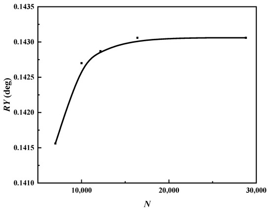
Figure 4.
Mesh convergence analysis.
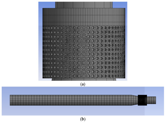
Figure 5.
Schematic diagram of the grid division. (a) Porous shell meshing diagram. (b) Spar meshing diagram.
3.2. Verification of Hydrodynamic Loads on Porous Structures
To validate the model, a numerical model consisting of a solid cylinder with an external diameter of a = 250 mm and a porous cylinder with an external diameter of b = 375 mm is considered. In the porous component, the holes have a circular form of radius r, satisfying the porosity τ = 0.2. The wall thickness of the porous structure is 3 mm and the effect of the wall thickness is ignored in the numerical calculation. The model is located in the water depth of 1 m and the height of the porous structure extends above the maximum amplitude of the incident waves. By comparison with the published numerical and experimental results of the dimensionless wave force [17], the reliability of the present numerical model is established as presented in Figure 6.
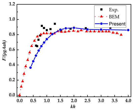
Figure 6.
Comparison of the wave forces on the cylinder with different calculation methods [17].
3.3. Validation of the Numerical Coupling Method
The hydrodynamic component of wave loading on the proposed structure is calculated using ANSYS AQWATM. Then, the result is converted into a suitable format and coupled with the aerodynamic loading component computed by Aerodyn15. The new coupling model is termed AQWA-FAST. Therefore, it is necessary to verify the reliability and accuracy of this new coupling method. It is verified by comparing with the results from the coupling program OpenFAST©. The related numerical modes used in both methods are displayed in Table 4. The Aerodynamic and hydrodynamic wave loading conditions for the model coupling validation are shown in Table 5.
Table 4.
Comparison of calculation models.
Table 5.
Aerodynamic and hydrodynamic loading conditions for the model coupling validation.
The motion comparisons for the different displacement modes are presented in Figure 7. The two different numerical methods produce small discrepancies in the calculated motion response in the three main degrees of freedom. Therefore, the numerical calculation method for the newly developed AQWA-FAST coupling procedure is deemed reliable.
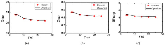
Figure 7.
Comparison of platform average-motion-response. (a) In surge. (b) In heave. (c) In pitch.
4. Results and Discussions
In order to investigate the hydrodynamic performance of the new floating platform system with the integrated porous shell, a six-degree-of-freedom displacement study comparing the original OC3-Hywind spar platform with the newly developed spar with the integrated porous shell is performed. Both floating platforms are provided with identical mooring system. The performance of each floating platform is investigated at different incident wave frequencies. The wave frequency range in this study is set to 0.045~0.2 Hz. A detailed analysis of the motion response at a single incident wave condition is presented first, followed by a motion response comparison study between the two model geometries over the range of incident wave conditions.
4.1. Detailed Analysis of Motion Response at Selected Wave Condition
In this section, the operating conditions H = 8 m, T = 10 s and V = 11.4 m/s are selected for the motion response of the platform both with and without the porous shell. The incident wave angle and wind speed direction are both set to 0°. In Figure 8, the motion of the floating platform is stable after 1000 s elapsed simulation time for both floating platforms under the applied loading conditions.
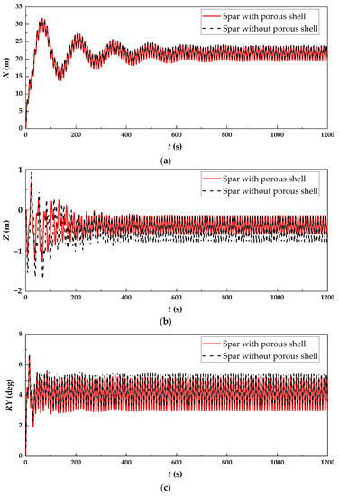
Figure 8.
Comparing the simulation results for two floating platforms under specific operating conditions. (a) In surge. (b) In heave. (c) In pitch.
Because the displacement of the floating platform is significant in the three directions of surge, heave and pitch when the incidence angle of both wave and wind is 0°, only the time-domain results in these degrees of freedom are analyzed. From Figure 8 and Figure 9 and Table 6, it can be observed that both floating platforms produce large motion responses under the joint action of wind and regular waves. The following analysis is performed according to the different motion freedoms.
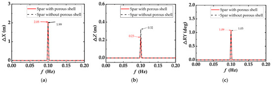
Figure 9.
Comparison of the fast Fourier transform (FFT) results for the two floating platforms in the different motion freedoms. (a) In surge. (b) In heave. (c) In pitch.
Table 6.
Comparison of peak motion response results for two floating platforms.
After the platform motion is stabilized, the spar with the porous shell produces a mean surge-motion response of 21.5 m in the positive direction of the X-axis and a periodic oscillation with an amplitude of about 2.05 m. The spar without the porous shell produces a mean surge-motion response of 22.1 m in the positive direction of the X-axis and a periodic oscillation with an amplitude of about 1.99 m. The results for the other two degrees of freedom are shown in Table 6. The slow drift results for the spar with the porous shell are all attenuated to some extent under these loading conditions, with the most obvious attenuation in the heave direction, exhibiting a reduction of 21.76%. Motion reductions of 7.13% and 2.4% are observed in the pitch and surge directions, respectively. The porous shell also has an effect on the oscillation amplitude of the stabilized floating platform. The most obvious attenuation is obtained in the heave degree of freedom, with a reduction of 27.3%, followed by increases of 3.6% and 3.0% in the pitch and surge directions, respectively.
4.2. Motion Equilibrium Position with Different Porosity
As shown in Figure 10, it can be seen that the motion equilibrium position in all three main freedoms directions progressively reduce with increasing wave period. This indicates that the motion equilibrium position of the spar-type floating platform is more sensitive to the wave period variation. It gradually levels off after the wave period increases to a certain level.
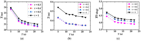
Figure 10.
Comparison of motion equilibrium position for floating platforms at varying porosity. (a) Surge motion. (b) Heave motion. (c) Pitch motion. (Porosity τ = 1 denotes the spar without porous shell.).
By comparing the motion equilibrium position of four floating platforms under different porous coefficient τ, the attenuating effects of the porous shell can be better observed. In Figure 10, it can be seen that the motion equilibrium position of the spar with the porous shell is smaller than that without the porous shell over the whole range of wave periods 5~22 s. As can be seen in Figure 10, an optimal stabilizing effect can be achieved when the porosity is 0.3. The maximum motion reduction of 2.4% can be achieved in the surge degree of freedom, and the maximum reduction of 7.13% can be achieved in pitch motion. It is of interest to note that the reduction in heave freedom amounted to 21.76%. This confirms that the effect of the porous shell on the floating platform is significant in reducing the motion equilibrium position, i.e., the drift distance. Additionally, the result shows that the change in porosity τ does not influence the average heave motion response, but the opposite effect is observed in the surge and pitch motions.
4.3. Response Amplitude Operator with Different Porosity
The variations of the motion response amplitudes in the three main degrees of freedom with four different porosities are depicted in Figure 11. As can be seen, the effect of the porous shell on the response amplitude is mainly dominant in the heave direction, where a significant reduction can be seen, especially at larger periods. At the smaller period wave conditions, T < 10, the response amplitude operators in heave are reduced by approximately 16%. A more pronounced effect is achieved at longer period waves, reaching an RAO heave reduction of 77% at a wave period of 20 s. The effects on the surge and pitch motions are minimal and are almost identical to the case of the spar without the porous shell. The detailed reasons for this behavior are discussed in the next sections.
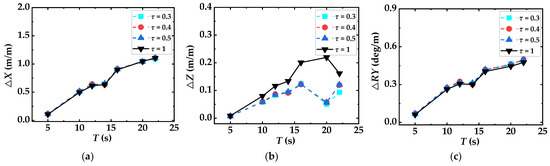
Figure 11.
Comparison of response amplitude for floating platforms with different porous porosities. (a) Surge. (b) Heave. (c) Pitch. (Porosity τ = 1 denotes the spar without porous shell.).
4.4. Response Amplitude Operator without Wind
From Figure 12, by comparing a floating platform with a porosity of 0.3 to a spar without porous in the absence of wind conditions, it was found that the effects in terms of surge and heave degrees of freedom were still small. However, for the heave degree of freedom, more pronounced suppression effects are produced at higher wave periods.
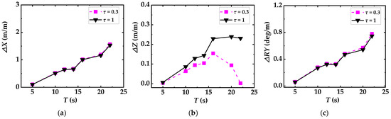
Figure 12.
Comparison of response amplitude for floating platforms without wind. (a) In surge. (b) In heave. (c) In pitch. (Porosity τ = 1 denotes the spar without porous shell.).
4.5. Hydrodynamic Load Analysis
Figure 13 compares the excitation wave forces in three main motion degrees of freedom. The maximum values of the surge, heave and pitch motions are generated at frequencies of 0.09 Hz, 0.08 Hz and 0.06 Hz, respectively. Compared with the spar without the porous shell, the excitation wave forces in surge and pitch on the spar with the porous shell is approximately the same at low frequencies f < 0.09 Hz and f < 0.06 Hz, respectively. The main reason is due to long wave effects which exhibit greater wave diffraction effects. The excitation wave forces in surge and pitch on the spar with the porous shell are slightly higher than those without the porous shell at high frequencies due to the increased porous shell area. Additionally, the exciting wave force in the heave direction on the spar with the porous shell decreases in the large frequency range compared with those observations for the model without the porous shell. This can be explained due to the flow field above the upward wetted surface of the spar is attenuated by the porous shell. A decrease of approximately 28.4% is found at two peaks. This result also explains the large reduction in the response amplitude and motion equilibrium position achieved in heave.
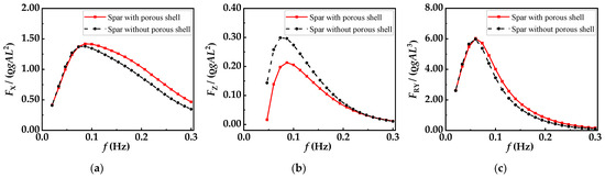
Figure 13.
Comparison of exciting wave forces in the three main freedom. (a) In surge. (b) In heave. (c) In pitch.
4.6. Structural Hydrodynamic Coefficients
4.6.1. Added Mass
Added mass coefficients can be expressed as the following:
where is the added mass, L = 9.4 m is the diameter of cylinder, k = 3 for (i, j = 1, 2, 3), and k = 5 for (i, j = 4, 5, 6).
In Figure 14, the added mass coefficients for both floating platforms are shown to be less affected by the variation in the incident wave frequency and generally tend to be stable. For the spar without the porous shell, the added mass coefficient is stable with a value of around 9.5 in surge and a value of 0.28 in heave. The coefficient value is greater in the pitch freedoms, at around 527. For the spar with the porous shell, the added mass coefficients is stable at around 9.8 in the surge, around 0.29 in heave, and approximately 540 in pitch. Comparing the added mass coefficients for the two floating platforms in different degrees of freedom reveals that the added mass coefficient of the spar with the porous shell is greater than that without porous shell. The increases in surge, heave and pitch are about 2.5%, 2.9% and 2.3%, respectively. The variation of the added mass indicates that the porous shell can reduce the motion response of the platform under actual working condition to a certain extent.
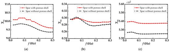
Figure 14.
Comparing the additional mass coefficient of two floating platforms. (a) In surge. (b) In heave. (c) In pitch.
4.6.2. Radiation Damping
The radiation damping coefficient can be expressed as the following:
is the radiation damping coefficient, is the radiation damping, L = 9.4 m is the diameter of cylinder, is the circular frequency, k = 3 for (i, j = 1, 2, 3), and k = 5 for (i, j = 4, 5, 6).
From Figure 15, it can be seen that the radiation damping coefficients for the two floating platforms are strongly influenced by wave frequency. The radiation damping of the two FOWTs has a similar trend with wave frequency variation, but there are significant differences in the magnitude. The spar with the porous shell has increased radiation damping peaks at both surge and pitch motions by 17% and 2%, respectively. In contrast to surge and pitch degrees of freedom, the radiation damping on the heave motion is reduced by about 50%. However, the order of magnitude of radiation damping on heave freedom is significantly less than that of surge and pitch freedoms. It is observed that the values of radiation damping in the high frequency band in surge and pitch freedom increase significantly. This demonstrates that the effect of the porous shell on radiation damping is more obvious in the high frequency region and less influential in the low frequency region. Considering the effects of the porous shell on radiation damping of FOWTs alone, the motion response of FOWTs on surge and pitch motions should be reduced. In fact, the motion response of the FOWTs is the result of the combined action of the excitation wave force, the added mass and the radiation damping.
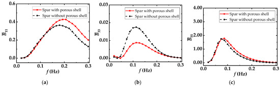
Figure 15.
Comparing the radiation damping coefficient of two floating platforms. (a) In surge. (b) In heave. (c) In pitch.
4.7. Full Coupled Analysis of Wind Turbine with Varied Angles between Incident Wave and Wind Load
In Figure 16, the angle between incidence wave direction and wind direction varies from 0° to 90°. As can be seen in the figure, the response amplitude of the floating platform is significantly influenced by the angle. The response amplitudes in surge and pitch decrease as the angle increases. When the angle is about 90°, their motion responses are near to 0. In contrast to the pitch and surge motions, the response amplitude in heave increase with the increase in the angle. By changing the angle between the incident wave and wind, it is observed that the influence of the porous shell on decreasing the motion response of floating platform are mainly reflected in the heave degree of freedom.
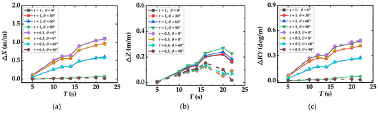
Figure 16.
Comparing the response amplitude with different angles between incident wave and wind. (a) In surge. (b) In heave. (c) In pitch.
5. Conclusions
In this article, a new offshore wind turbine platform is proposed based on the innovation of the OC3-Hywind spar. The new offshore wind turbine platform combines the advantages of porous structures widely used in conventional offshore engineering and its performance is compared with the conventional OC3-Hywind spar.
By comparing the motion equilibrium position and response amplitude of floating platforms over a range of incident wave periods from 5~22 s, it can be seen that the spar with the porous shell exhibits better stability than the traditional OC3-Hywind spar. Moreover, by analyzing the exciting wave forces, added mass and radiation damping of the two floating platforms, the explanations for the effect of reduced motion response are determined. The exciting wave forces on the spar with the porous shell are not significantly different from those of the OC3-Hywind spar in surge and pitch. However, the exciting wave forces significantly decrease in heave. In terms of added mass and radiation damping, the values observed for the spar with the porous structure are significantly larger than the values exhibited by OC3-Hywind spar, which is in agreement with the effects of incorporating the porous shell in other marine structures. By adding the porous structure, the motion equilibrium position of the offshore wind turbine platform can be effectively reduced about 2% in surge, 7% in pitch and 22% in heave. Its effects on the response amplitude operator are not significant in surge and pitch. Nevertheless, the addition of the porous shell demonstrates significant levels of motion reduction in heave displacement, up to 16–77%. This shows that the combination of porous shells and FOWTs has potential for future development. Furthermore, it is possible to combine the porous shells with other FOWT structures which will have the effect of inhibiting motion. For example, the OC4 Semisubmersible Floating Offshore Wind Turbine spar could be retrofitted with the porous shell to inhibit its motion. This stabilizing process may increase the efficiency of the FOWT and prolong its design life offsetting the initial additional construction costs. Moreover, The OC4 Semisubmersible Floating Offshore Wind Turbine has a larger contact area with the still water surface, allowing more space for the installation of the porous shell—the addition of this component may provide more beneficial effects to this structure.
In this study only the effects of regular wave conditions and constant wind speeds on the floating wind turbine platform have been considered. The reduction of response amplitude operator in surge and pitch are not significant. In future work, the study will be extended to address these limitations. Future studies will also consider adjusting the size and porosity of the porous shells to achieve better motion inhibition. In real sea states, wind and wave conditions are complex and the effects of turbulent winds and irregular waves will be considered in the extended research.
Author Contributions
Conceptualization, Y.Y. and D.N.; methodology, Y.Y., D.N. and R.M.; software, Y.Y.; validation, Y.Y., D.N. and S.D.; formal analysis, Y.Y.; investigation, Y.Y.; resources, D.N.; data curation, Y.Y.; writing—original draft preparation, Y.Y.; writing—review and editing, D.N., S.D., R.M. and M.Q.; visualization, Y.Y.; supervision, D.N.; funding acquisition, D.N. All authors have read and agreed to the published version of the manuscript.
Funding
This work is supported by the National Natural Science Foundation of China (Grant No. U22A20242) and LiaoNing Revitalization Talents Program (Grant No. XLYC2002033).
Data Availability Statement
Not applicable.
Conflicts of Interest
The authors declare no conflict of interest.
References
- Veers, P.; Dykes, K.; Lantz, E.; Barth, S.; Bottasso, C.L.; Carlson, O.; Clifton, A.; Green, J.; Green, P.; Holttinen, H.; et al. Grand Challenges in the Science of Wind Energy. Science 2019, 366, 443. [Google Scholar] [CrossRef] [PubMed]
- Mishnaevsky, L.; Hasager, C.B.; Bak, C.; Tilg, A.-M.; Bech, J.I.; Rad, S.D.; Fæster, S. Leading Edge Erosion of Wind Turbine Blades: Understanding, Prevention and Protection. Renew. Energy. 2021, 169, 953–969. [Google Scholar] [CrossRef]
- Carraro, M.; De Vanna, F.; Zweiri, F.; Benini, E.; Heidari, A.; Hadavinia, H. CFD Modeling of Wind Turbine Blades with Eroded Leading Edge. Fluids 2022, 7, 302. [Google Scholar] [CrossRef]
- Chen, L.; Biswajit, B. Fatigue Load Estimation of a Spar-type Floating Offshore Wind Turbine considering Wave-current Interactions. Int. J. Fatigue. 2018, 116, 421–428. [Google Scholar] [CrossRef]
- Yue, M.; Liu, Q.; Li, C.; Ding, Q.; Cheng, S.; Zhu, H. Effects of heave Plate on Dynamic Response of Floating Wind Turbine Spar Platform under the Coupling Effect of Wind and Wave. Ocean Eng. 2020, 201, 107103. [Google Scholar] [CrossRef]
- Lin, W.; Lai, B.; Chen, X.; Zhao, C.; Tang, Y. A Novel Structural Form of Semi-Submersible Platform for a Floating Offshore Wind Turbine with Hydrodynamic Performance Analysis. Appl. Mech. Mater. 2013, 477, 109–113. Available online: https://www.scientific.net/AMM.477-478.109 (accessed on 27 April 2023).
- Rao, M.; Nallayarasu, S.; Bhattacharyya, S. Numerical and Experimental Studies of heave Damping and Added Mass of Spar with heave Plates Using Forced Oscillation. Appl. Ocean Res. 2021, 111, 102667. [Google Scholar] [CrossRef]
- Hegde, P.; Nallayarasu, S. Investigation of heave Damping Characteristics of Buoy Form Spar with heave Plate near the Free Surface Using CFD Validated by Experiments. Ships Offshore Struct. 2022, 1–18. [Google Scholar] [CrossRef]
- Yang, J.; He, E. Coupled Modeling and Structural Vibration Control for Floating Offshore Wind Turbine. Renew. Energy. 2020, 157, 678–694. [Google Scholar] [CrossRef]
- Huang, Z.; Li, Y.; Liu, Y. Hydraulic Performance and Wave Loadings of Perforated/slotted Coastal Structures: A Review. Ocean Eng. 2011, 38, 1031–1053. [Google Scholar] [CrossRef]
- Dai, J.; Wang, C.; Utsunomiya, T.; Duan, W. Review of Recent Research and Developments on Floating Breakwaters. Ocean Eng. 2018, 158, 132–151. [Google Scholar] [CrossRef]
- Downie, M.; Graham, J.; Hall, C.; Incecik, A.; Nygaard, I. An Experimental Investigation of Motion Control Devices for Truss Spars. Mar. Struct. 2000, 13, 75–90. [Google Scholar] [CrossRef]
- Molin, B. On The Added Mass and Damping of Periodic Arrays of Fully or Partially porous disks. J. Fluid Struct. 2001, 15, 275–290. [Google Scholar] [CrossRef]
- Tao, L.; Daniel, D. Hydrodynamic Performance of Solid and Porous heave Plates. Ocean Eng. 2008, 35, 1006–1014. [Google Scholar] [CrossRef]
- An, S.; Faltinsen, O. Linear Free-surface Effects on a Horizontally Submerged and Perforated 2D Thin Plate in Finite and Infinite Water Depths. Appl. Ocean Res. 2012, 37, 220–234. [Google Scholar] [CrossRef]
- An, S.; Faltinsen, O. An Experimental and Numerical Study of heave Added Mass and Damping of Horizontally Submerged and Perforated Rectangular Plates. J. Fluids Struct. 2013, 39, 87–101. [Google Scholar] [CrossRef]
- Mackay, E.; Shi, W.; Qiao, D.; Gabl, R.; Davey, T.; Ning, D.; Johanning, L. Numerical and Experimental Modelling of Wave Interaction with Fixed and Floating Porous Cylinders. Ocean Eng. 2021, 242, 110–118. [Google Scholar] [CrossRef]
- Saha, S.; Bora, S.; Das, S. Time-dependent Water Wave Scattering by a Bottom-mounted Porous Compound Cylinder Fitted with an Annular Porous Lid. Waves Random Complex Media. 2023, 1–22. [Google Scholar] [CrossRef]
- Ding, Q.; Li, C.; Yu, N.; Hao, W.; Ji, J. Numerical and Experimental Investigation into the Dynamic Response of a Floating Wind Turbine Spar Array Platform. J. Mech. Sci. Technol. 2018, 32, 1106–1116. [Google Scholar] [CrossRef]
- Jonkman, J. Definition of the Floating System for Phase IV of OC3; National Renewable Energy Laboratory: Golden, CO, USA, 2010; pp. 509–513. [Google Scholar] [CrossRef]
- Zhang, H.; Wang, H.; Cai, X.; Xie, J.; Wang, Y.; Zhang, N. Research on the Dynamic Performance of a Novel Floating Offshore Wind Turbine Considering the Fully-Coupled-Effect of the System. J. Mar. Sci. Eng. 2022, 10, 341. [Google Scholar] [CrossRef]
- Yang, Y.; Bashir, M.; Michailides, C.; Li, C.; Wang, J. Development and Application of an Aero-hydro-servo-elastic Coupling Framework for Analysis of Floating Offshore Wind Turbines. Renew. Energy 2020, 161, 606–625. [Google Scholar] [CrossRef]
- Chen, P.; Chen, J.; Hu, Z. Review of Experimental-Numerical Methodologies and Challenges for Floating Offshore Wind Turbines. J. Marine. Sci. Appl. 2020, 19, 339–361. [Google Scholar] [CrossRef]
- Masciola, M.; Jonkman, J.; Robertson, A. Implementation of a Multisegmented, Quasi-Static Cable Model. In Proceedings of the Twenty-third International Offshore and Polar Engineering Conference, Anchorage, AK, USA, 30 June–4 July 2013. [Google Scholar]


Disclaimer/Publisher’s Note: The statements, opinions and data contained in all publications are solely those of the individual author(s) and contributor(s) and not of MDPI and/or the editor(s). MDPI and/or the editor(s) disclaim responsibility for any injury to people or property resulting from any ideas, methods, instructions or products referred to in the content. |
© 2023 by the authors. Licensee MDPI, Basel, Switzerland. This article is an open access article distributed under the terms and conditions of the Creative Commons Attribution (CC BY) license (https://creativecommons.org/licenses/by/4.0/).