Abstract
Sustainable development in coal mining requires a continuous and efficient method of coal extraction. Research shows that gob-side entries retained through roof cutting retained gob-side (RCGE) are vital for improving mining efficiency, enhancing coal recovery rates, and enabling continuous production. However, the mechanism of surrounding rock deformation during close-distance co-mining of coal seams with this technique is not yet clear. For the Jiaokou coal mine in China, due to an unreasonable stagger distance between upper and lower working faces, the gob-side entries retained at the 9102 tailgate and 10102 headgate experience severe rock pressure, leading to significant prop damage and a sharp reduction in the cross-section of the entry. This greatly hampers the reuse of these entries. To investigate this issue, we established a model to study the stress distribution of surrounding rocks at different stagger distances (20 m, 40 m, 60 m, 80 m, and 120 m) through numerical simulation and optimized the support parameters for the retained entries. Our research found that when the subsidence of the roof in the upper coal seam exceeds 0.74 m but is less than 1.33 m, there is sliding instability in the mining body. When the subsidence exceeds 1.33 m, the mining body will rotate and deform, causing significant mining pressure within the retained entry. A stagger distance of 40 m between the upper and lower working faces can reduce pressure on the face during the mining of the lower coal seam. Extensive field measurements of rock pressure revealed that the damage rate of the single column in the gob-side entries of the upper and lower coal seams does not exceed 5% and 1%, respectively. In summary, this study provides a practical method to reduce damage to entries during the mining process, thereby increasing the continuous production capability of the coal mine. This is critical for the sustainable development of coal mining.
1. Introduction
With the growth of global energy demand, coal, as an important source of energy, has seen an increase in both consumption and production [1,2]. However, due to the increasing scarcity of coal resources, coal mines around the world are facing mining difficulties, and mining has caused varying degrees of environmental damage [3,4,5,6].
In some areas, such as the United States and India, room and pillar mining is often used in underground mines [7,8]. The room and pillar mining method is a kind of pillar system mining method. Coal pillars of different shapes are left in the coal room during coal mining, and the coal pillars temporarily support the roof in the coal mining room [9,10,11]. In shallow coal seams, the thickness of the covering layer should not exceed 500 m, the inclination angle should be small, single coal seams or non-short-distance coal seams are used, the roof is more than moderately stable, and the floor is hard. Under these conditions, the coal quality is medium hard or above medium hard. There is no hard gangue; the gas emission is low, and the coal seam will easily spontaneously ignite, etc. This approach is more suitable. Many scholars have conducted research on mine pressure appearance and corresponding support measures within the mining process [12,13,14].
Compared to thick and easily mined coal seams, the mining conditions and geological situations of close-distance coal seams are more complex [15,16], yet they account for a significant portion of coal reserves. Co-mining of close-distance coal seams is an effective mining method to address these challenges [17,18]. However, the traditional co-mining of close-distance coal seams presents significant risks and low recovery rates, making the development of safer and more efficient mining technologies a current priority [19,20].
Gob-side entry retaining technology involves preserving some goaf in the entry, where the collapsed goaf naturally forms one side of the entry. The successful implementation of this technology not only increases coal recovery rates but also greatly enhances safety. Specifically, the roof of the gob-side entry can be effectively preserved, improving the safety of mining operations [21]. Many scholars have studied the gob-side entry retaining technology under different roof and burial conditions [22,23]. Especially in deep areas, the successful use of gob-side entry retaining has solved the serious threat brought by enormous geo-stress to the entry.
However, in areas with shallow burial, due to the thin and multi-layered nature of coal seams, traditional co-mining of close-distance coal seams presents many problems. The close proximity of the roadways leads to multiple disturbances, resulting in difficult-to-support roadways. Therefore, we combined gob-side entry retaining technology with co-mining of upper and lower coal seams and conducted research on roof cutting retained gob-side entry in close-distance coal seams co-mining. Considering that in recent years, with the development of technology, the technical condition systems for monitoring reservoirs and mines have been significantly improved [24,25,26]. These systems aim to monitor various parameters of mines in real-time, including geo-stress, gas pressure, coal seam temperature, etc., to ensure the safety of miners and improve the operating efficiency of mines. This provides us with more detailed geological production data and safety guarantees as we attempt to solve these issues.
In close-distance coal seams combined mining, a key issue is determining the reasonable offset between upper and lower coal seam entries [27,28]. This is because the floor may undergo plastic failure after the upper coal seam is mined, which makes the roof of the lower coal seam entry prone to collapse. The interaction between upper and lower coal seams during mining can affect the surrounding rock structure and stress distribution. Too small of an offset can make it difficult to control the surrounding rock, while too large of an offset can affect production continuity and output stability. Therefore, the layout of the lower coal seam entry is divided into stable pressure zone layout and depressurized zone layout, both of which aim to reduce the impact of disturbance caused by the upper coal seam mining on the stability of the lower coal seam entry [29,30]. However, in actual engineering, a reasonable entry layout is difficult to achieve due to geological conditions and mining plans. Entries that are too close can lead to problems such as surrounding rock deformation, mining pressure, increased support difficulty, and dangerous gas concentration [31,32,33,34,35].
However, there is currently no clear conclusion on the mechanism of cutting the top and unloading pressure along the gob-side entry in close range coal seams, so it is necessary to conduct in-depth research on the characteristics of overall roof movement of upper and lower coal seams, the deformation mechanism of surrounding rock, and the mining pressure law of the interaction between the roadway and surrounding rock.
Taking the 9102 tailgate and the 10102 headgate in Jiaokou Coal Mine as the background, analyze the spatiotemporal evolution of the overlying strata structure and the deformation of surrounding rock. By constructing a mechanics model, analyze the theoretical mechanism of the roof, floor, and surrounding rock in the cutting of the top and unloading pressure along the gob-side entry at different stages. Using FLAC3D simulation software, study the stress field variation during the mining process of the No. 9 and No. 10 coal seams, and explore the influence of the upper and lower coal seam working faces on the stress distribution of the surrounding rock in the gob-side entry. Finally, optimize the support scheme and apply it to engineering.
2. Field Practice of Gob-Side Entry Retained
In Jiaokou Coal Mine, the method of co-mining and roof cutting gob-side entry retaining is adopted for close-distance coal seams, where the horizontal distance between the 9102 tailgate and the 10102 headgate is 6 m, the vertical distance is 10 m, and the cross sections of the 9102 tailgate and the 10102 headgate are 4700 mm × 3000 mm and 4700 mm × 3500 mm, respectively. First, the 9102 working face starts mining, and the 9102 tailgate begins gob-side entry retaining. When the working face advances 120 m, the 10102 working face starts mining, and the 10102 tailgate begins gob-side entry retaining, with a staggered distance of 120 m between the working faces, as shown in Figure 1.
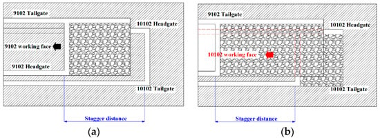
Figure 1.
Relationship between goaf of upper and lower coal mining faces and gob-side entry. (a) 9102 working face location (b) 10102 working face location.
As shown in Figure 2, the slit holes are located 200 mm above the roof, with a spacing of 600 mm. The advanced support method adopts 4.2 m π-shaped beams + single columns (one beam, three columns) with single column spacings of 2800 mm and 1200 mm, while the lagging support method adopts 4.2m π-shaped beams + single columns (one beam, eight columns) with single column spacings of 1000 mm, 1000 mm, 400 mm, 400 mm, 400 mm, 400 mm, and 400 mm. The advanced support distance for the 9102 tailgate is 20 m, and the lagging support distance is 240 m. As the working face advances, the single columns lagging by 240 m are partially recovered for pedestrian and transportation purposes. The advanced support distance for the 10102 headgate is 80 m, and the lagging support distance is 200 m. As the working face advances, the single columns lagging by 200 m are partially recovered and reused for pedestrian and transportation purposes.
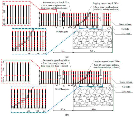
Figure 2.
Advance support and lagging support gob-side entry. (a) 9102 tailgate advance support and lagging support gob-side entry (b) 10102 headgate advance support and lagging support gob-side entry.
Due to unscientific historical mining in the No. 9 coal seam of Jiaokou Coal Mine, the setup entry of the 9103 working face cannot be excavated, as shown in Figure 3a. Therefore, ventilation was improved by excavating a roadway at the setup entry to connect the 9102 tailgate and 10102 headgate. This allows the 10102 headgate, 10102 tailgate, and 9102 headgate to be ventilated simultaneously while the 9102 tailgate returns the airflow. That is, the No. 9 and No. 10 coal seams share a common return airway, as shown in Figure 3b.

Figure 3.
Ventilation method in the mining area. (a) Traditional ventilation gob-side entry (b) Actual ventilation gob-side entry.
The lithology of the roof and floor of 9102 and 10102 working faces is shown in Figure 4. The thickness of the No. 9 coal seam is 0.30 m to 1.75 m, averaging 1.04 m, with a simple structure, generally containing 0 to 1 layer of gangue, and is a stable and mostly mineable coal seam in the whole area. The roof is L1 limestone, and the floor is mudstone and sandy mudstone. The thickness of the No. 10 coal seam is 1.74 m~3.93 m, with an average of 3.04 m, and a simple structure containing 1~3 layers of gangue, stable thickness, and is mineable across the whole area.
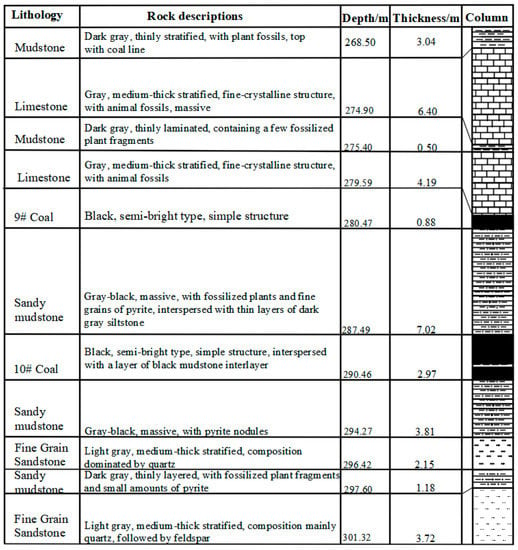
Figure 4.
Borehole diagram.
3. Overlay Transport Characteristics and Surrounding Rock Deformation Mechanism
3.1. Deformation and Damage Characteristics of the Roof
Figure 5 demonstrates the roof damage and key block changes during the mining process of the upper and lower group coal seam working face. As the coal seam mining advances, the overlying rock subsidence leads to changes in key blocks A, B, and C. Among them, the position of A is stable, C moves down, and B is affected by A and C and rotates and sinks. When the lower group of the coal seam is mined, the roof sinking increases and the structural stability of key block E is weakened, which in turn affects the structural stability of key block B, and the mine pressure shows obviously. The damage to the bottom plate has a significant impact on the stability of the key block, and the degree and extent of the damage are related to the difficulty of safe mining of the coal seam of the lower group. In order to clarify the deformation mechanism of the surrounding rock, it is necessary to analyze the sliding instability and rotary deformation mechanism of key block B in the mining process of the upper and lower group coal seams.
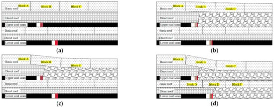

Figure 5.
The process of roof failure during mining at the working face. (a) End of upper and lower roadway excavation (b) Start of upper group coal seam mining (c) End of upper and lower roadway excavation (d) Start of upper group coal seam mining (e) End of upper and lower roadway excavation (f) Start of upper group coal seam mining.
3.2. Research on the Damage Mechanism of the Surrounding Rock Structure
In the process of the workover of the upper and lower groups of coal seams in the near coal seam with cutting top unloading pressure along the air stay, the force analysis of the key blocks A, B, and C is carried out as shown in Figure 6. The force of the key blocks (assumed to be A, B, and C) of the overlying roof rock of the upper group coal seam is analyzed. Assuming that these key blocks are articulated, it is necessary to analyze the slip instability and rotary deformation of key block B. Here, it is simplified to a two-dimensional problem, and some basic parameters are set for the blocks. The force analysis parameters and the key parameters of the rock masses are shown in Table 1.

Figure 6.
Stress analysis of the roof of the upper and lower coal seams. (a) End of upper and lower roadway excavation (b) Start of upper group coal seam mining.

Table 1.
Stress analysis and key parameters of rock mass.
According to the hydrostatic equilibrium equation for the point we have Equation (1).
For the point there is Equation (2).
Slip destabilization analysis of key block B during the mining of the upper group of coal seams, according to the balance of lateral forces on the key block B, Equation (3) can be listed.
where, and are the horizontal restraint force of the articulated structure on the key block B, respectively, is the support force transmitted by the bracket below the key block B, is the load borne by the key block B. Consider that the maximum shear force on key block B occurs when it is in the sliding instability state, which satisfies so that Equation (3) can be simplified to Equation (4).
Based on:
where is the shear area between the key blocks C and B, is the shear stiffness, and is the hinge distance. Substituting into Equation (3) yields Equation (6).
In order to ensure that the key block B does not slip and destabilize, it is necessary to ensure that the horizontal binding force of the articulated structure on B is greater than or equal to the friction force on the key block B. To this end, Equation (7) is established.
Then, according to the moment balance equation, we can obtain Equation (8).
The condition for determining whether the key block B slips and destabilizes is Equation (9).
Simplify and organize to obtain Equation (10).
The condition for the key block B not to undergo rotary deformation during mining of the upper group coal seam is Equation (11).
Equation (11) simplified and organized as Equation (12).
The slip instability and rotary deformation conditions of key block E in the lower group coal seam are almost the same as the derivation of key block B in the upper group coal seam mining, so no derivation is made.
Since it is assumed that the block C sinks as a whole , as in Figure 4b, then and decrease and increase , respectively, where is the rock density, kg/m3; is the acceleration of gravity, kg/m2, at which point there are Equations (13) and (14).
Slip destabilization analysis of key block B during mining of the lower group coal seam, according to the balance of lateral forces on key block B and previous derivation, the condition for lower group coal seam mining to satisfy key block B without slip destabilization is Equation (15).
where, is the horizontal binding force of the articulated structure on the key block A and B, and are the frictional shear reactions of the articulated structure of the key block A and C, respectively, and are the friction coefficients between the rocks, and is the support force transmitted by the brace below the key block B.
Considering the overall sinking of block C by , the horizontal and articulated forces on the key block B will also change. According to the principle of mechanical equilibrium, the condition that the key block B does not slip and destabilize is satisfied by Equation (16).
Equation (16) is expanded and organized to obtain Equation (17).
In the lower group coal seam mining, when block B undergoes rotary deformation, Equation (18) needs to be satisfied.
Equation (18) is simplified and organized to obtain Equation (19).
According to the production geology and filed practice, take = 4.17 m, = 6.2 m, = 1.4, = 0.2, = 22 GPa, = = 15°, = 2450 kg·m−3, = 9.8 kg·m−2, = 0.35, and = 275 m, = 4.18 MPa, = 3.9 MPa, = = 3.16 MPa. By substituting them into Equations (17) and (19), it can be obtained that ≥ 0.74 m, ≥ 1.33 m.
Finally, when the subsidence of the goaf roof in the upper group of coal seams falls within the range of , block B experiences sliding instability. When , block B will rotate and deform, and both situations will cause severe mining pressure in the roadway, leading to large deformation of the surrounding rock and posing a threat to the stability of the next group of coal seam roadways and the safety of mining work. Therefore, in the mining of the lower group of coal seams, it is necessary to further consider the reasonable stagger distance between the upper and lower working faces to reduce the stress concentration caused by the mining impact of the upper group of coal seams.
4. Numerical Simulation of Rock Pressure in Gob-Side Entry
In order to study the effect of different working face stagger distances on gob-side entry stability under the same mining situation of upper and lower coal seams, we designed a numerical simulation plan for coal seam excavation under different working face stagger distances. The advancing distance of the upper coal seam working face is larger than that of the lower coal seam, and the stagger distances of the upper and lower coal seam working faces are 20 m, 40 m, 60 m, 80 m, and 120 m.
Combined with the lithology, spatial distribution, and the mining scheme of the 9102 and 10102 chutes of the Jiaokou coal mine, a numerical model of 335 m × 320 m × 50 m was established (see Figure 7), taking into account parameters such as the size of the coal roadway, the width of the working face, and the horizontal and vertical distances. The rock mechanics parameters (see Table 2) and contact parameters (see Table 3) were defined, and the boundary conditions were set after pre-splitting. Pre-splitting and roof cutting are achieved by using the interface unit in FLAC3D to define the cracking behavior. The model contains two support schemes, scheme I and scheme II, which adopt different anchor spacing, row spacing, and number of anchors, respectively. For scheme I, anchor spacing is 1100 mm, row spacing is 1600 mm, it has one anchor cable in the center of the roof, and 3 and 4 anchor cables in the 9102 return wind chute and 10102 transport chute of the roadway gang, respectively. For scheme II, two anchor cables are added on the basis of scheme I, the distance between its anchors is 700 mm, and the distance between its rows is 800 mm. After adding support, the coal seams 9 and 10 were excavated in steps, and the changes in the surrounding rock stresses in the two roadways during the retrieval process were studied.
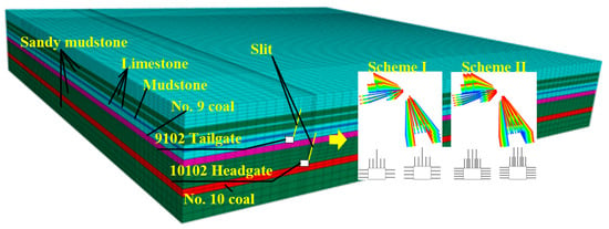
Figure 7.
Numerical model.

Table 2.
Rock mechanics parameters.

Table 3.
Contact mechanics parameters of slit.
4.1. The Influence of the Upper and Lower Group of Working Face Retrieval on the Stress Distribution of the Gob-Side Entry Surrounding Rock
In Figure 8, contour lines are drawn for the stress distribution of the upper and lower group coal seam along the gob-side entry at the different working face stagger distances. According to Figure 8a–e, it is known that the stress value of the lower group of coal roadways is smaller than that of the upper group of coal roadways. It can be seen that the upper group coal seam roof cut destroys the roof stress transfer, and with the stagger distance increase in the working face’s advance, the stress on the solid coal side and the roof increases, and the roadway gang is always in a high-stress state. However, when the working face stagger distance is 40 m, see Figure 8b, the stress of the upper coal seam gob-side entry solid coal side is 9 MPa, the stress of the lower coal seam gob-side entry solid coal side is 8 MPa, the difference between the two is not significant. This indicates that the mining activity of the upper coal seam face has the greatest impact on the lower part at this time. When the working face is staggered by 20 m, the roof of the upper coal seam working face has not yet fully collapsed. For the safety and efficiency of mining the lower coal seam, we believe that the suitable working face offset is 40 m.
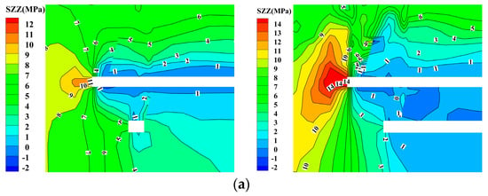
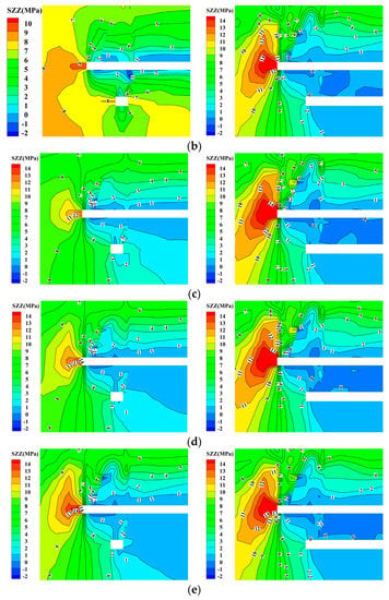
Figure 8.
Stress distribution of gob-side entry under different working face stagger distances. (a) working face stagger distance is 20 m (b) working face stagger distance is 40 m (c) working face stagger distance is 60 m (d) working face stagger distance is 80 m (e) working face stagger distance is 120 m.
When the lower coal seam is retrieved, the horizontal to vertical stress distribution of the top plate gob-side entry and mining of the lower group coal seam will affect the stress distribution of the upper group coal seam gob-side entry but will not change the stress peak. With the increase in the working face of the lower group coal seam, the high-stress range of the surrounding rock of the upper group coal gob-side entry increases. The effect of the slit along the empty roadway of the lower group coal seam is different from that of the upper group coal seam, and the slit gob-side entry of the lower group coal seam maintains the original stress state of the roof plate under the activity of overburdened rock in the mining area and the change in surrounding rock of upper group coal seam roadways so that no stress concentration is generated.
4.2. Quarry Stress Distribution Characteristics
In Figure 9, the stress magnitude along the slit side of the gob-side entry is compared and analyzed with the back of the mining area. In Figure 9a, the stresses on the solid coal side with a slit are larger compared with the stress values on the uncut side. This indicates that the bending and sinking of the upper mining area during the lower group of coal seam retrieval makes the solid coal side with cut seams suffer greater support stresses. The reason for this phenomenon is that the overburden activity in the lower mining area leads to an increase in the overburden activity space in the mining area of the upper coal seam. In this case, the overburden in the upper mining area will continue to sink, destroying the stability of the original articulated structure. As the overburden in the upper mining area rotates and slips, the stress will be redistributed and reach a new equilibrium state, resulting in differences in stress values. The overburden activity weaken the regulating effect of upper group coal seam cuttings on stress distribution, which increases the supporting stress on the solid coal side.

Figure 9.
Three-dimensional stress map of the roof strata along both sides of the empty roadway at the same horizontal level.
The lower group coal seam roadway cut will destroy the overburden articulation structure, and the stress should be smaller compared with the uncut case, as shown in Figure 9b.
Combining the whole upper and lower group coal seam retrieval processes, it can be found that the upper group coal seam is more influenced by mining activities; therefore, when the actual project is carried out, it is necessary to pay close attention to the potential influence of the mining activities of the lower group coal seam on the stability of the upper gob-side entry and take appropriate support measures to ensure the safety and stability of the roadway.
4.3. Comparative Analysis of Different Support Schemes
According to Figure 10a,b, in support scheme I, the maximum settlement of the roof slab of the 9102 return wind chute is 17.9 cm, which is located at model 95.7 m; while under scheme II, the maximum settlement of the roof slab is 15.3 cm. The short-term support effect of scheme II is 14.5% higher than that of scheme I. In the analysis of the settlement of the roof slab of the 10102 transport chute in the No. 10 coal seam, the maximum settlement of scheme I is 1.4 cm, and that of scheme II is 1.28 cm, with a difference of 0.16 cm, and the short-term support effect of scheme I is only improved by 7.8%. The support effect of both options meets the engineering requirements.
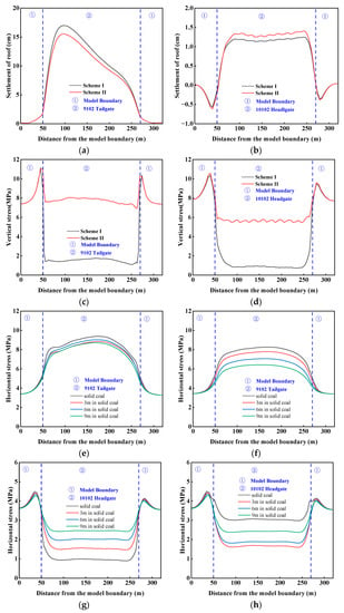
Figure 10.
Comparison of support schemes. (a) 9102 tailgate roof settlement (b) 10102 headgate roof settlement (c) 9102 tailgate roof vertical stress (d) 10102 headgate roof vertical stress (e) Stress on solid coal side of 9102 tailgate in scheme I (f) Stress on solid coal side of 9102 tailgate in scheme II (g) Solid coal side stress of 10102 headgate in scheme I (h) Solid coal side stress of 10102 headgate in scheme II.
As shown in Figure 10c,d, the vertical stress distribution of the roof plate of the 9102 tailgate and the 10102 headgate shows that the minimum vertical stress of the 9102 roof plate is 1.05 MPa under scheme I and 6.9 MPa under scheme II. The support effect of scheme II is reduced by 37.3% and still has a better effect under the influence of subsequent overburden transport and mining movement; the support effect of scheme I is reduced by 88.2%, and it can hardly play a supporting role under the influence of subsequent overburden transport. In the 10102 headgate, the support effect of the two support schemes is reduced by 91.1% and 35.7%, respectively.
Although the change in the horizontal stress of the roadway gang directly affects the stability of the roadway, and the presence or absence of anchor rods and anchor cables does not affect this conclusion, in Figure 10e–h, after comparing the horizontal stress of the roadway gang in the upper and lower along-air roadway, it is found that: in the close-distance coal seam co-mining with pre-split gob-side retaining project, the horizontal high-stress distribution on the solid coal side of the upper group coal seam can be made under the condition of appropriately increasing the support strength. The range is reduced. Because the range of horizontal mining-induced stress changes reduced, thereby reducing the probability of rock bursts and other hazards, which is conducive to the long-term stability of the gob-side entry.
5. Industrial Trials
By analyzing the numerical simulation research results of the overburden transport characteristics and the mineral pressure performance law gob-side entry, the engineering application of the technology of close distance coal seams roof cutting gob-side entry retaining in the same mining in the close coal seam is carried out.
The 9102 tailgate and the 10102 headgate are both rectangular in the cross section, with dimensions of 4700 mm × 3000 mm and 4700 mm × 3500 mm, and the 9102 tailgate is cut into the bottom of the coal seam, while the 10102 headgate is cut along the top of the bottom. The cross section and plan of the gob-side entry roof reinforcement support are shown in Figure 11.
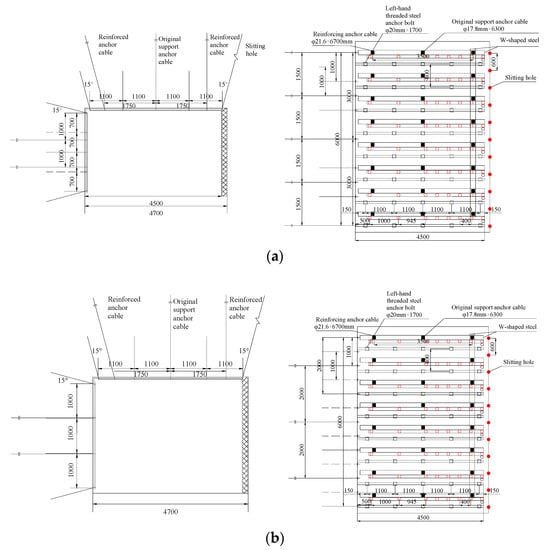
Figure 11.
Design of roof reinforcement support for gob-side entry (a) 9102 tailgate roof reinforcement design (b) 10102 headgate roof reinforcement design.
After using this design scheme on site, the single column breakage of upper group coal does not exceed 5%, and the lower group coal basically does not exceed 1%, which indicates that the engineering application of near coal seam co-mining top cutting and pressure removal along the empty stay is successful.
6. Discussion
This study presents an in-depth examination of deformation mechanisms and rock pressure behavior during gob-side entry retaining in close distance co-mining of upper and lower coal seams. Our results highlight the significant impact of staggered distances between the working faces on the stress distribution of the surrounding rock, with a distance of 40 m, demonstrating optimal performance.
Despite these findings, there are limitations in our study that warrant further research. First, our model is reliant on accurate geological data and complex numerical simulations, which may not always be feasible. Second, while our model primarily considers staggered distances, other factors that might influence deformation and rock pressure behavior are not extensively addressed. Future studies should explore these influences for a more comprehensive understanding of gob-side entry stability.
7. Conclusions
In conclusion, this research focused on understanding the deformation mechanisms and rock pressure behavior in gob-side entry retaining during close distance co-mining of upper and lower coal seams. A structural model was developed, and numerical simulations were performed to assess the impact of varying working face staggered distances on the stress distribution of surrounding rock.
The impact of roof subsidence (Δy) on the stability of gob-side entry retaining during the co-mining of upper and lower coal seams was investigated. Additionally, it was found that when the subsidence of the goaf roof in the upper group of coal seams falls within the range of 0.74 m ≤ Δy ≤ 1.33 m, block B experiences sliding instability. In cases where Δy ≥ 1.33 m, block B undergoes rotation and deformation. Both of these scenarios result in severe mining pressure in the roadway, leading to significant deformation of the surrounding rock.
A working face staggered distance of 40 m was identified as the most effective choice, leading to significant improvements in the performance of support schemes. This optimal distance resulted in single column damage rates of no more than 5% for the upper coal seam group and 1% for the lower coal seam group.
These insights can inform the development of strategies to enhance mining safety and efficiency in gob-side entry retaining for close distance co-mining projects.
Author Contributions
Writing—original draft, X.X.; Writing—review & editing, C.W.; Project administration, Y.Y. and C.W. All authors have read and agreed to the published version of the manuscript.
Funding
This work was supported by the National Natural Science Foundation of China (Grant No. 51404167); Natural Science Foundation For Young Scientists of Shanxi Province (Grant No. 201901D211066); Scientific Research Grant Project for Returned Overseas Students in Shanxi Province (HGKY2019038); Teaching Reform Innovation Project for Higher Education Institutions in Shanxi Province (J2019055); China postdoctoral science foundation funding project (Grant No. 2016M590151).
Data Availability Statement
The article data used to support the findings of this study are included within the article.
Conflicts of Interest
The authors declare no conflict of interest.
Nomenclature
| Key block C mining gangue stiffness, N/m | |
| Key block C mining area gangue displacement, m | |
| , , | Self-weight of key blocks A, B and C, kN |
| , , | Key block A, B, C structure friction shear reaction force, kN |
| , , | Key blocks A, B and C are loaded, kN |
| Support force transmitted by the bracket underneath the critical block B, kN | |
| Distance of the support transfer key block B, m | |
| Key block C mining area gangue support force, kN | |
| , | Horizontal binding force of the structure on A and B, B and C, kN |
| Length of key blocks A, B, C, m | |
| Height of key blocks A, B, C, m | |
| Turning angle of key block B with respect to A, ° | |
| Turning angle of key block B with respect to C, ° | |
| Crushing and swelling coefficient | |
| Residual swelling factor | |
| Thickness of the ith collapsed rock layer, m | |
| Distance of key block C sinks as a whole, m | |
| Area of the shear between the key blocks C and B, m2 | |
| Shear stiffness of key block C and B | |
| Hinge structure length of key block C and B, m |
References
- IEA. World Energy Outlook 2022; IEA: Paris, France, 2022. [Google Scholar]
- Hudeček, V.; Šancer, J.; Zubíček, V.; Golasowski, J. Experience in the Adoption of Room & Pillar Mining Method in the Company OKD, a.s., Czech Republic. J. Min. Sci. 2017, 53, 99–108. [Google Scholar] [CrossRef]
- Tajduś, K.; Misa, R.; Sroka, A. Analysis of the Surface Horizontal Displacement Changes Due to Longwall Panel Advance. Int. J. Rock Mech. Min. Sci. 2018, 104, 119–125. [Google Scholar] [CrossRef]
- Jiránková, E.; Mučková, J.; Jadviščok, P.; Vochta, R.; Molčák, V.; Havlicová, M. Geodetic Monitoring of the Surface within the Trial Operation of the Room and Pillar Mining Method in the Ostrava-Karvina Coal District. Int. J. Clean Coal Energy 2016, 5, 37–44. [Google Scholar] [CrossRef]
- Jongpradist, P.; Tunsakul, J.; Kongkitkul, W.; Fadsiri, N.; Arangelovski, G.; Youwai, S. High Internal Pressure Induced Fracture Patterns in Rock Masses Surrounding Caverns: Experimental Study Using Physical Model Tests. Eng. Geol. 2015, 197, 158–171. [Google Scholar] [CrossRef]
- Majdi, A.; Hassani, F.P.; Nasiri, M.Y. Prediction of the Height of Destressed Zone above the Mined Panel Roof in Longwall Coal Mining. Int. J. Coal Geol. 2012, 98, 62–72. [Google Scholar] [CrossRef]
- Ghasemi, E.; Ataei, M.; Shahriar, K. An Intelligent Approach to Predict Pillar Sizing in Designing Room and Pillar Coal Mines. Int. J. Rock Mech. Min. Sci. 2014, 65, 86–95. [Google Scholar] [CrossRef]
- Shekhar, N.; Pal, S.; Jaiswal, A.; Hazara, P. Numerical Modelling for Prediction of Ground Subsidence Over Room and Pillar Mining in an Underground Coal Seam. In Soil Dynamics, Earthquake and Computational Geotechnical Engineering; Muthukkumaran, K., Ayothiraman, R., Kolathayar, S., Eds.; Springer Nature: Singapore, 2023; pp. 155–165. [Google Scholar]
- Zhou, N.; Du, E.; Li, M.; Zhang, J.; Dong, C. Determination of the Stability of Residual Pillars in a Room-and-Pillar Mining Goaf under Eccentric Load. Energy Rep. 2021, 7, 9122–9132. [Google Scholar] [CrossRef]
- Waclawik, P.; Ptacek, J.; Konicek, P.; Kukutsch, R.; Nemcik, J. Stress-State Monitoring of Coal Pillars during Room and Pillar Extraction. J. Sustain. Min. 2016, 15, 49–56. [Google Scholar] [CrossRef]
- Skrzypkowski, K. The Influence of Room and Pillar Method Geometry on the Deposit Utilization Rate and Rock Bolt Load. Energies 2019, 12, 4770. [Google Scholar] [CrossRef]
- Mallı, T.; Yetkin, M.E.; Özfırat, M.K.; Kahraman, B. Numerical Analysis of Underground Space and Pillar Design in Metalliferous Mine. J. Afr. Earth Sci. 2017, 134, 365–372. [Google Scholar] [CrossRef]
- Alejano, L.R.; Arzúa, J.; Castro-Filgueira, U.; Malan, F. Strapping of Pillars with Cables to Enhance Pillar Stability. J. S. Afr. Inst. Min. Metall. 2017, 117, 527–540. [Google Scholar] [CrossRef]
- Skrzypkowski, K.; Korzeniowski, W.; Zagórski, K.; Zagórska, A. Flexibility and Load-Bearing Capacity of Roof Bolting as Functions of Mounting Depth and Hole Diameter. Energies 2019, 12, 3754. [Google Scholar] [CrossRef]
- Tan, Y.L.; Zhao, T.B.; Xiao, Y.X. In Situ Investigations of Failure Zone of Floor Strata in Mining Close Distance Coal Seams. Int. J. Rock Mech. Min. Sci. 2010, 47, 865–870. [Google Scholar] [CrossRef]
- Qin, Y.; Xu, N.; Zhang, Z.; Zhang, B. Failure Process of Rock Strata Due to Multi-Seam Coal Mining: Insights from Physical Modelling. Rock Mech. Rock Eng. 2021, 54, 2219–2232. [Google Scholar] [CrossRef]
- Zhang, Y.; Zhang, C.L.; Wei, C.C.; Liu, Y.D.; Zhang, S.Q.; Zhao, J.J. The Study on Roadway Layout in Coordination of Mining Coal Seams Base on Failure of Floor Strata. Adv. Mater. Res. 2014, 889–890, 1362–1374. [Google Scholar] [CrossRef]
- Cheng, Z.; Ma, H.; Sang, C.; Liu, Y. Experimental Research on Dynamic Evolution Characteristics of Roof Movement and Mining-Induced Stress of Superimposed Mining in a Close Distance Coal Seam Group. Geotech. Geol. Eng. 2021, 39, 13–24. [Google Scholar] [CrossRef]
- Lian, Z.; Wang, J.; Hao, C. Numerical Simulation and Experimental Research of Surrounding Rock Deformation of Floor Roadway under Short-Distance Coal Seam Group Combined Mining. J. Coal. Sci. Eng. China 2010, 16, 230–234. [Google Scholar] [CrossRef]
- Wu, G.; Fang, X.; Bai, H.; Liang, M.; Hu, X. Optimization of Roadway Layout in Ultra-Close Coal Seams: A Case Study. PLoS ONE 2018, 13, e0207447. [Google Scholar] [CrossRef]
- Liu, H.; Zhang, B.; Li, X.; Liu, C.; Wang, C.; Wang, F.; Chen, D. Research on Roof Damage Mechanism and Control Technology of Gob-Side Entry Retaining under Close Distance Gob. Eng. Fail. Anal. 2022, 138, 106331. [Google Scholar] [CrossRef]
- Tan, Y.L.; Yu, F.H.; Ning, J.G.; Zhao, T.B. Design and Construction of Entry Retaining Wall along a Gob Side under Hard Roof Stratum. Int. J. Rock Mech. Min. Sci. 2015, 77, 115–121. [Google Scholar] [CrossRef]
- Fan, D.; Liu, X.; Tan, Y.; Yan, L.; Song, S.; Ning, J. An Innovative Approach for Gob-Side Entry Retaining in Deep Coal Mines: A Case Study. Energy Sci. Eng. 2019, 7, 2321–2335. [Google Scholar] [CrossRef]
- Martirosyan, A.V.; Ilyushin, Y.V. Modeling of the Natural Objects’ Temperature Field Distribution Using a Supercomputer. Informatics 2022, 9, 62. [Google Scholar] [CrossRef]
- Martirosyan, A.V.; Ilyushin, Y.V. The Development of the Toxic and Flammable Gases Concentration Monitoring System for Coalmines. Energies 2022, 15, 8917. [Google Scholar] [CrossRef]
- Skrzypkowski, K. Case Studies of Rock Bolt Support Loads and Rock Mass Monitoring for the Room and Pillar Method in the Legnica-Głogów Copper District in Poland. Energies 2020, 13, 2998. [Google Scholar] [CrossRef]
- Zhang, Z.; Deng, M.; Bai, J.; Yan, S.; Yu, X. Stability Control of Gob-Side Entry Retained under the Gob with Close Distance Coal Seams. Int. J. Min. Sci. Technol. 2021, 31, 321–332. [Google Scholar] [CrossRef]
- Li, Q.; Wu, G.; Kong, D. Study on Stability of Stope Surrounding Rock under Repeated Mining in Close-Distance Coal Seams. Geofluids 2022, 2022, e9630942. [Google Scholar] [CrossRef]
- Shen, F.; Song, Y.; Zheng, J.; Zhao, W.; Yang, M.; Ma, H.; Shao, Z. Study on Stress Evolution Law and Control Technology of Roadway Formed by Roof Cutting during Crossing Overlying Remained Coal Pillar. Energy Explor. Exploit. 2023, 41, 745–765. [Google Scholar] [CrossRef]
- Zhang, Z.; Wang, W.; Li, S.; Bai, J.; Hao, S.; Wu, H.; Yu, X. An Innovative Approach for Gob-Side Entry Retaining With Thick and Hard Roof: A Case Study. Teh. Vjesn. 2018, 25, 1028–1036. [Google Scholar] [CrossRef]
- He, F.; Xu, X.; Qin, B.; Li, L.; Lv, K.; Li, X. Study on Deformation Mechanism and Control Technology of Surrounding Rock during Reuse of Gob Side Entry Retaining by Roof Pre-Splitting. Eng. Fail. Anal. 2022, 137, 106271. [Google Scholar] [CrossRef]
- Fan, D.; Liu, X.; Tan, Y.; Song, S.; Gu, Q.; Yan, L.; Xu, Q. Roof Cutting Parameters Design for Gob-Side Entry in Deep Coal Mine: A Case Study. Energies 2019, 12, 2032. [Google Scholar] [CrossRef]
- Zhang, Y.; Wang, X.; Zhang, F.; Li, M.; Wang, G.; Chen, D.; Li, G.; Zhao, X. Retracement Ground Pressure Appearance and Control of the Working Face under the Overlying Residual Pillar: A Case Study. Energies 2023, 16, 1701. [Google Scholar] [CrossRef]
- Wang, K.; Huang, Y.; Gao, H.; Zhai, W.; Qiao, Y.; Li, J.; Ouyang, S.; Li, W. Recovery Technology of Bottom Coal in the Gob-Side Entry of Thick Coal Seam Based on Floor Heave Induced by Narrow Coal Pillar. Energies 2020, 13, 3368. [Google Scholar] [CrossRef]
- Xinjie, L.; Xiaomeng, L.; Weidong, P. Analysis on the Floor Stress Distribution and Roadway Position in the Close Distance Coal Seams. Arab. J. Geosci. 2016, 9, 83. [Google Scholar] [CrossRef]
Disclaimer/Publisher’s Note: The statements, opinions and data contained in all publications are solely those of the individual author(s) and contributor(s) and not of MDPI and/or the editor(s). MDPI and/or the editor(s) disclaim responsibility for any injury to people or property resulting from any ideas, methods, instructions or products referred to in the content. |
© 2023 by the authors. Licensee MDPI, Basel, Switzerland. This article is an open access article distributed under the terms and conditions of the Creative Commons Attribution (CC BY) license (https://creativecommons.org/licenses/by/4.0/).