1. Introduction
Among the recent developments related to energy storage techniques cited by [
1,
2], the flywheel energy storage system (FESS) is the one that can exchange electrical energy with the power grid [
3]. Technically, it consists of an electrical machine, a DC–AC converter, a DC link capacitor, and a solid disc made of steel or composite materials. Unlike other storage systems, such as the battery energy storage system (BESS), FESS is an environmentally friendly short- to medium-term storage device that has the ability to perform multiple charge and discharge cycles. These energy characteristics make the FESS a relevant choice for various applications in the electrical field, such as power quality improvement, power smoothing, renewable energy integration, stability improvement, etc. Therefore, the flywheel energy storage system (FESS) can be applied in different fields, from small (micro-) satellites up to large area power grids, as described in reviews [
4,
5]. Similarly, energy storage systems (ESS) with ultra-long lifetimes of more than twenty years using matrix converters and flywheels to compensate for frequency and voltage fluctuations in the power grid are solutions to be considered [
6,
7], as well as in the transportation domain for the design and sizing of electric buses rapid chargers [
8] and for the optimization and control of a hybridized battery–flywheel energy storage system during electric vehicle (EV) braking instants [
9]. In addition, regarding their lifetime, flywheels have the advantage of being maintenance-free for more than twenty years.
The manuscript is a post-IEEE ITEC 2017 and SEE Sdewes2022 for which a first approach of the work has already been published by authors in [
10]. The present manuscript focuses on the progress of the previously published work, including novel achieved results, in particular, the calculation of the electro thermal highest efficiency of the SiC power inverter for usage profiles, and the dynamic evaluation of the converter on a homemade emulator that reproduces, in the laboratory, the technological behavior of a flywheel energy storage system (FESS) dedicated to electric vehicle recharging.
The purpose of this paper is to propose the concept and realization of an originally designed bidirectional 50 kW three-phase DC–AC inverter with novel silicon carbide (SiC)-based MOSFETs (Metal Oxide Semiconductor Field Effect Transistors) technology used for the power supply of a flywheel energy storage system dedicated to electric vehicle charging.
The research work, which is mainly experimental, provides real technological innovation in both the design of the power converter itself and the hardware emulator since they utilize the most recent wide band-gap silicon carbide semiconductors and an original robust control strategy.
The work is carried out in the framework of the French “VIVE” project supported by the French Ministry of Industry and the Region of Paris Île de France. Highest efficiency in reversible mode, compactness, and thermal enhancement are the targeted objectives for the converter prototype. The three-phase DC–AC silicon carbide inverter prototype is tested on an original home-made PWM test-bench, in which semiconductor switches are controlled using the modulated hysteresis controller and is able to emulate the working of the PMSM–flywheel system. High frequency PWM tests, speed cycle operating, and thermal losses are evaluated. The adopted design for realization and control strategy should permit the DC–AC inverter to reach the highest efficiency.
The paper is organized as follows: In
Section 2, a recent literature overview is proposed on flywheel energy storage systems and silicon carbide converters used as power electronics supply for FESS.
Section 3 focuses on the SiC-based DC–AC inverter design for the EV-charging flywheel system.
Section 4 presents experimental pulse width modulated (PWM) switching tests, interface driver card design for the SiC MOSFETs switches, and DC bus hardware design.
Section 5 presents the experimental validation for the SiC DC–AC inverter implemented on the original and modular double-converter PWM test bench controlled using the modulated hysteresis method. Finally,
Section 5 ends with the evaluation of static and speed cycle thermal losses and calculation of the SiC DC–AC inverter efficiency.
2. State-of-the-Art Overview of FESS and Their Power Converter Interfaces
This section provides an overview of the scientific literature on flywheel energy storage systems (FESS) and silicon carbide power converters. The section begins with an inventory of the power electronics topologies powering FESS, and then lists the various applications of flywheel technology as an energy storage device in several applicative fields. Examples of recent research and achievements in this area are reported hereafter.
A bidirectional converter (BDC) is essential in applications where energy storage devices are considered. These applications deal with transportation, uninterruptible power supplies without batteries, flywheel energy storage systems, etc. Bidirectional energy flow through buck and boost modes of operation, as well as high power density and energy efficiency, are the most important requirements for these systems. The work reported by authors in [
11] demonstrates a new BDC topology based on a judicious combination of a silicon-controlled rectifier and an insulated gate bipolar transistor (IGBT) involving an innovative control strategy aimed at minimizing or even cancelling switching losses through zero voltage (ZVS) and zero current (ZCS) switching techniques. According to the work described in [
12], flywheel energy storage systems can be used to store and release energy in high power pulsed modes. For example, based on the use of a homopolar synchronous machine driving a FESS, the authors S.J. Amodeo et al. developed a power flow control law based on a high-performance model using the feedback linearization methodology. The synthesis of a Luenberger observer for torque and rotor speed control allows the implementation of a sensor-less control strategy. The authors of [
13] have proposed a new flywheel energy storage system that leads augmentation of the energy stored by the flywheel by 20% compared to existing systems. Basically, boost converters are used to increase the voltage in those power systems. The main limitation of a boost converter is its dependence on its maximum voltage gain that can be achieved on the ratio of source resistance to load resistance, which limits the amount of energy recovered from a flywheel and reduces the efficiency for low input voltages. In [
14], Koos van Berkel et al. argue that mechanical hybrid powertrains have the potential to improve vehicle fuel economy at a relatively low cost; this is enabled by the addition of a flywheel and mechanical transmission components to the conventional powertrain. Authors present a systemic approach to optimize both the topology and size of the flywheel, which are the main design criteria for a mechanical hybrid powertrain. The topology was optimized from a set of more than twenty existing mechanical hybrid powertrains described in the literature.
In addition, the fuel economy potential for each hybrid powertrain is evaluated using an optimal energy controller and modular component models for different flywheel sizes and driving mission profiles. The global cost of hybridization is estimated based on the type and size of the components. Meanwhile, the authors have shown that for each of the studied hybrid powertrains, the fuel savings provide a return on the investment in hybridization well before the end of the vehicle’s lifetime (from about 50%). Thus, the optimal size of the flywheel with energy storage capacity is approximately equivalent to the kinetic energy of the vehicle during urban driving (approx. 32 mph). Furthermore, [
15] reports that fast charging stations (FCS) are capable of charging plug-in hybrid electric vehicles (PHEVs) in less than half an hour, which is an attractive feature for vehicle owners since the charging time becomes similar to that of refueling at a conventional public gas station. However, since FCS outlets are rated up to 100 kW, they may expose the power grid to strong power constraints in a scenario where there will be a large deployment of public FCSs distributed among the grid. In [
16], the authors propose a control and management strategy for plug-in electric vehicle (PEV) fast charging stations equipped with a flywheel energy storage system. The main role of the FESS is not to compromise the predefined charge profile of the PEV battery during the utilization of an active auxiliary power service. In other terms, when active power is not extracted from the grid, the FESS provides the power necessary to maintain the continuous charging process of the plug-in electric vehicle battery.
The authors in [
17] demonstrate that silicon carbide (SiC)-based power switching devices offer significant performance improvements over conventional silicon-based devices. These enhanced performance characteristics allow for a significant reduction in the losses, size, and weight of power converters in hybrid/electric vehicle powertrains. However, the fast-switching capability of SiC devices makes them more vulnerable and susceptible to parasitic inductances in the circuit. Therefore, the impact of interconnecting inductances on the overvoltage caused during the blocking transient of SiC devices must be considered.
To conclude on this review section about flywheel energy storage systems and their power interfaces, authors in [
18,
19] present recent advanced and predictive control strategies for flywheel energy storage systems and their power electronic interfaces to achieve stable and efficient operation for various applications including grid frequency stabilization during disturbances [
20] and FESS utilization in regional railway applications [
21].
3. Silicon Carbide DC–AC Inverter for the EV Flywheel Charging System
As discussed in
Section 2, flywheel energy storage systems (FESS) are increasingly becoming potential candidates for a hybrid energy storage source in combination with batteries in electric vehicles. For example, the system of kinetic energy recovery by electromagnetic slip coupling presented by [
22] is potentially a cost-effective and efficient solution for transferring energy between a vehicle and a light-weight flywheel. According to authors, the proposed kinetic energy recovery system (KERS) can be less expensive and complex than flywheel batteries because it requires only one electrical machine and one power electronic converter. In addition, the storage system is capable of recovering a greater amount of mechanical power than its rated electrical power. Furthermore, since a large amount of the energy exchange is in mechanical form, only a fraction of the recovered energy needs to be processed by the power electronic converter. The research described in [
23] was also aimed at exploring the effect of a flywheel on the torsional vibration characteristics of a power split hybrid powertrain. Other recent research presented by the authors themselves concerns dual front-wheel drives [
24], dynamic charging of electric vehicles, or their use as reversible dynamic power sources for EV charging stations.
The work presented in this manuscript is part of the French VIVE project (VIVE: “Volant d’Inertie pour Véhicules Electrifiés”) coordinated by AER-Atmostat Company (Villejuif, France), with the support of the French Ministry of Industry and Region of Paris-Île de France in the framework of the FUI (Fonds Unique Interministériel) grant agreement, in which the objective is to manufacture, characterize, and implement a flywheel system designed and manufactured by AER-Atmostat for EV-charging [
10]. From the general powertrain shown in
Figure 1, the presented study focuses on the three-phase DC–AC inverter (in dashed red lines in
Figure 1), electrically connected to the variable DC bus (580 V up to 620 V), and supplying the 60 kW-neodymium iron boron permanent magnet synchronous motor (PMSM) with eight magnetic poles, whose frequency of the fundamental voltage varies within the range of 100 Hz to 400 Hz depending on the rotor mechanical speed (3000 to 6000 rpm).
In the black square in
Figure 1, there is the industrial flywheel system (massive disk) surmounted by the three-phase AC motor inserted under an upper “bell” metal shape. The flywheel system with its PMSM motor/generator and interface inverter is connected through the DC bus to a three-phase reversible converter ensuring current reinjection/supply with the 380 V/50 Hz grid network and is connected to a mixed DC–AC three-phase plant for EV-dynamic recharging. A two-level control strategy is used for the powertrain control. Level 1 deals with supervision and security issues, having as inputs the different use-case scenarios (named as macroscopic level). Level 0 (close-up control level) includes the control strategy in (d,q) the park reference frame for the three-phase PMSM currents and provides, through a real-Time prototyping system, the PWM signals to the gates of the three-phase DC–AC inverter transistors. A DC voltage security limit up to V
DCmax = 700 V is added for the inverter protection.
In the FESS, a three-phase resistive bloc (named security resistors) has been added at the input stage of the motor–flywheel system (
Figure 1), enabling the flywheel energy discharge, in case of an emergency situation, in twelve minutes approximately.
For designing the DC–AC inverter prototype and to meet the research objectives, silicon carbide (SiC) MOSFETs in a 1200 V/300 A half-bridge configuration have been adopted from the newest market technology. The objective is to achieve high efficiency, compactness, and thermal performance for the DC–AC power converter, in order to meet industrial challenges for the civil implementation of the EV-charging flywheel energy storage system. Such targeted objective is to reach the highest efficiency in both reversible energy flows for the 60 kW flywheel/PMSM/inverter system. For switching constraints, up to 100 kHz (max) driver card have been used.
Figure 2a illustrates the power (Watt) achieved by the 60 kW PMSM from Phase Motion Control S.p.A company vs. speed (rpm: revolution per minute). The AC motor is able to run under a variable speed from 3000 to 6500 rpm, depending on the steel composition of the massive flywheel. The objective is to maintain a constant power over the speed range, hence implying field weakening operation and imposing a current limitation up to 144 A Rms (root mean square value) (203 A maximal value) for thermal and technological reasons. At a low speed, for a low motor back-emf (back electro-motive force) voltage, active power is linearly limited to 50 kW (linear gray–blue curve) and 60 kW (linear gray curve).
First switching tests have been performed on a SiC half-bridge leg and are reported in
Section 4.
Figure 2b illustrates the laboratory experimental set-up for the switching tests of the 1200 V/300 A half-bridge with its high speed driver card connected to the gates. Initial tests have already been performed in the range of 16 to 20 kHz. The switching frequency is increased up to 24 kHz for the thermal loss evaluation and DC–AC converter efficiency calculation. A snubber capacitor has been added in order to minimize the voltage overshoot and oscillations during the switching times.
Figure 3 shows a comparison between the module efficiency between classical IGBT silicon technology from SEMIKRON
© (Nuremberg, Germany) and silicon carbide MOSFETs from CREE
® (Wolfspeed
© Group, Durham, NC, USA) for the same component caliber and PMSM power values. Efficiencies have been calculated analytically using the manufacturer’s datasheets of the semiconductors. A gain of 5% is obtained for the same power constraint (at 60 kW) using the silicon carbide technology.
5. Experimental Validation
5.1. Experimental Switching Tests for the SiC MOSFETs
The proposed hardware emulator architecture is original; it has been completely home-made and designed in the laboratory. It is composed of two bi-directional converters; the “tester” composed of three IGBT/Diode Silicon PWM half-bridges based on Infineon Technologies (Neubiberg, Germany) semiconductor technology EconoDUAL
TM FF450R12ME3 (1200 V, 450 A) with trench fieldstop IGBT3 and emitter controlled high efficiency diode (right side in Figure 11), and the SiC CREE
® CAS300M12BM2 (1200 V, 300 A) DC–AC PWM inverter under test (DUT) (left side in
Figure 9).
Both inverters are linked with three high frequency filtering (L = 1 mH) inductances from SMP Company (Long Island City, NY, USA) and are powered by a 600 V
DC power supply. The “tester” emulates the behavior of the motor/flywheel system. It authorizes 200 Amax in the DC side, 500 Ap-p in sinusoidal current waveform, and up to 500 Hz fundamental frequency. The switching frequency ranges from 0 up to 50 kHz. The strategy integrates current control (Ia, Ib, Ic), and thermal (thermistor) and voltage protection (V
DClim= 700 V
DC max). The DUT SiC inverter is voltage controlled. The strategy is an intersected PWM. The modulation reference voltage amplitude (Vmod*) is given with respect to the back-emf gain K = 0.53√3 V/s of the PMSM. The output of the PWM controller provides the gate duty cycles (d) to the SiC MOSFETs (ga, gb, gc,
ga,
gb,
gc). The switching frequency Fs has fixed set to 16, 20, and 24 kHz. Duty cycle calculation for the SiC converter, with V
DC = 600 V, is as follows in Equation (1):
The “tester” IGBT/diodes inverter is current controlled. The three phase currents (Ia, Ib, Ic), which represent the PMSM phase currents, are controlled using an original modulated hysteresis current controller (HCC), as shown in
Figure 10a, based on the modulated hysteresis method, which is detailed hereafter. The switching frequency, F, is synchronized with the frequency, Fs, of the DUT SiC inverter, with a limitation up to Flim ≤ 50 kHz maximum. The output of the modulated hysteresis controller provides the gate duty cycles for the Infineon IGBTs semiconductors (ha, hb, hc,
ha,
hb,
hc). Different load currents can be imposed thanks to the IGBT tester, and are representative of motor behavior. In the studied flywheel emulator application, the fundamental modulation frequencies are imposed from 200 Hz to 400 Hz, emulating the motor speed (3000 to 6000 rpm). The principle of the testing bench is original, hence, it enables the possibility to test all types of DUT inverters, and further to investigate the ageing mechanisms of the semiconductors under specific dynamic PWM constraints or specific load constraints.
5.2. Original Reversible PWM Double Converter Tester for Hardware Emulator
In order to control the IGBT/Diode “tester” converter, playing the role of a PMSM emulator, the modulated hysteresis technique has been employed. The principle of the method is detailed and explained in the following paragraph.
B.K. Bose presents, in [
25], an adaptive hysteresis band control method in which the bandwidth is modulated according to system parameters to keep the modulation frequency at a nearly constant value. Although the technique is applicable to AC motor drives and other types of loads, the modulated hysteresis method maintains constant the switching frequency of IGBT transistors. The hybrid controller, called a modulated hysteresis controller, combines, on the one hand, the robustness properties of a hysteresis controller, and the zero static error of a linear proportional integral (PI) controller on the other, with high robustness properties with respect to variations in system parameters, as shown in previous works [
25,
26].
The principle of the method consists of superimposing to the reference current (i
ref*) a modulated triangular signal (i
tr) with an appropriate amplitude A
tr and frequency f
tr (
Figure 10b). As a consequence, a modulated reference current (i
mod*) is generated, which constitutes the new reference for the current control loop, as given by Equation (2).
A judicious choice for Atr and the hysteresis bandwidth Bh lead to imposing the switching frequency of the IGBTs transistors so that they are equal to that of the triangular signal one. It should be noted that the chosen switching frequency is a trade-off between the current ripple rate and the switching losses. Indeed, a higher switching frequency value increases the switching losses of the transistors, negatively impacting the global converter efficiency; however, on the other hand, for a given phase-inductance value, a too small switching frequency generates an important current ripple, which leads to electrical constraints on the semiconductor switches. The modulated hysteresis method is robust and needs only a few parameters in order to be implemented (DC-link voltage source amplitude, the cyclic inductance of the PMSM machine, and the desired switching frequency). Moreover, the knowledge of a precise model for the PMSM machine is not mandatory.
Results of previous studies concerning the modulated hysteresis method in the motor operating mode show that (A
tr + B
h) should verify inequality (3) in order to impose the switching frequency of the transistors equal to that of the triangular signal one:
With the above defined parameters, the dynamic of the phase current during switching instants is improved and becomes close to that of the obtained current when the classical hysteresis method is applied. In addition, the modulated hysteresis method still offers the advantage of a constant switching frequency for IGBTs.
As for the modulated hysteresis method, M.A. Shamsi Nejad et al., in [
26], presented the study and modeling of the original hybrid current controller. The latter guarantees a high dynamic response in a fixed-frequency mode of operation, zero static error, and high robustness properties with respect to system parameter variations. In order to model the nonlinear current controller, different modeling tools have been developed by the authors. First, a high frequency average model is proposed. It allows evaluation of the mean dynamic properties of the method (bandwidth, time response, and overshoot). To study the behavior of the current ripple due to the switching effect, a second model, based on the construction of a 3D bifurcation diagram and the definition of a “form” function, is established. This model allows evaluation of the nature of the profile imposed by the state trajectory and to prove that the system operates at a fixed switching frequency.
Figure 11 shows the global testing bench: DC–AC SiC inverter connected to the IGBT/Diode tester, developed at SATIE laboratory.
5.3. Evaluation of the Losses and SiC DC–AC Inverter Efficiency
The three-phase DC–AC SiC inverter is water cooled. An appropriate heat-sink has been calculated. Thermal losses P (Watt) are given by the following Equation (4),
where
= 2.9 L/mn is the water cooling flow, C
p is the specific heat capacity of water = 4 180 J · kg
−1 · K
−1, and (T
wo, T
wi), respectively, are the output and input water temperatures, obtained by experimental recording.
Analytical losses, including copper (Joule) losses and switching losses are deduced from SiC semiconductor datasheets and calculated using Formula (5):
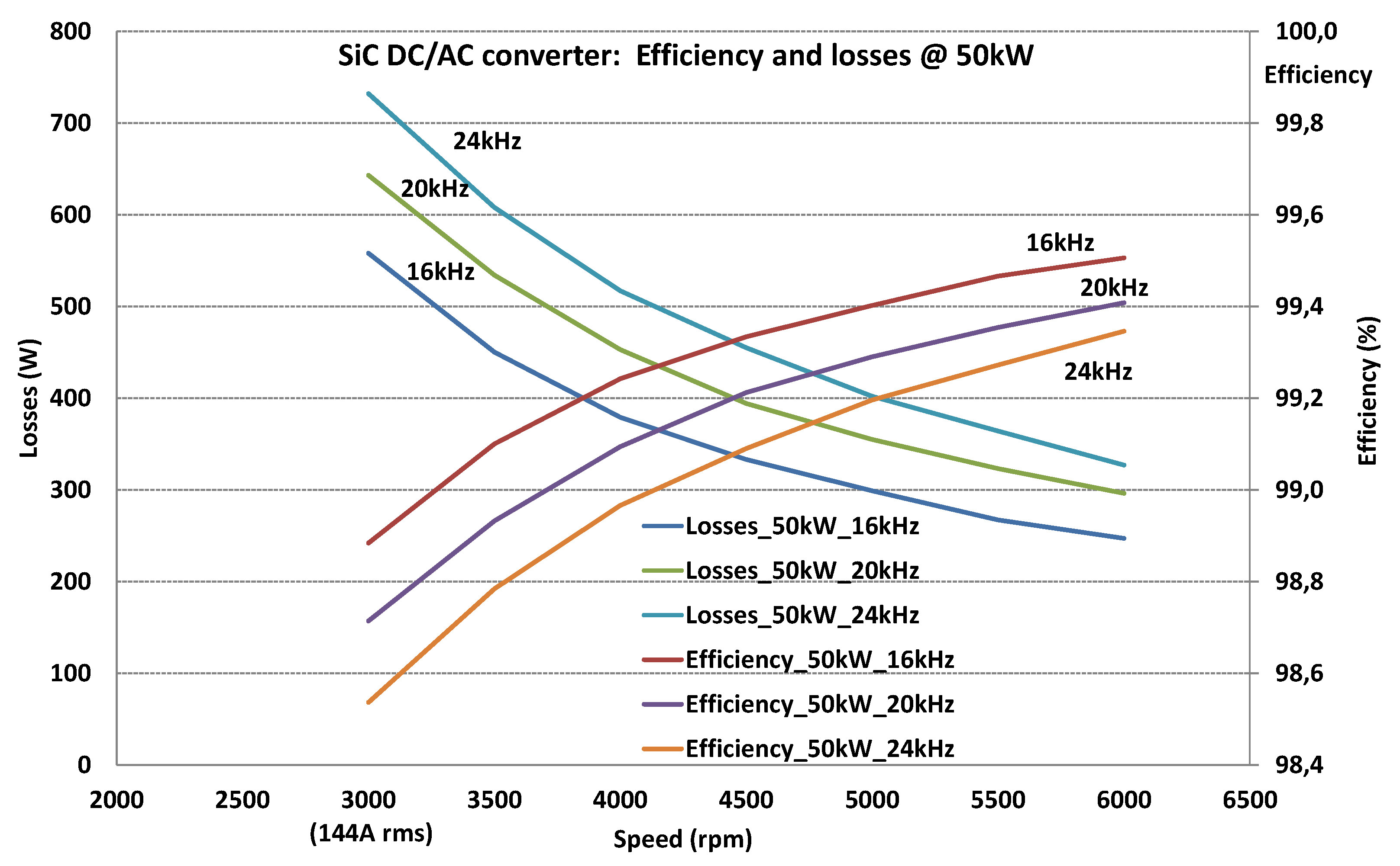
Analytically, for 144 A
rms, which is the maximal current constraint, for 24 kHz switching frequency, R
dsON = 3.5 mΩ at ambient temperature 25 °C, RG = 5Ω (external gate resistance present on the driver card), E
on = 5.25 mJ, E
off = 1.9 mJ, the calculated losses are 732 W, which is in accordance with the losses evolution at 3000 rpm (144 A); see results in
Figure 12.
For 20 kHz, the losses are 647 W, and for 16 kHz, the losses become 561 W.
Efficiencies (in %) are calculated for static points, with Equation (6), for 50 kW transmitted power:
The program code for the calculation of losses and efficiency is based on Matlab-Simulink
®, r2020a (MathWorks, Inc., Natick, MA, USA)and calculates analytically the thermal losses using Equation (4) and the efficiency using Equation (6); the input data is the experimentally recorded set of parameters and the results are then given in
Figure 12 and
Figure 13.
Thermal losses for speed cycle are calculated for each emulated speed value, by knowing the current amplitude, and for different switching frequencies.
Efficiencies of the SiC converter (from 16 kHz to 24 kHz) are between 99.5% and 99.3%.
Figure 13 represents the thermal losses for a speed up and down cycle from 3000 to 6000 rpm (time range from 0 to 600 s), then from 6000 down to 3000 rpm (time range from 600 to 1200 s). The time for current injection is 2 × 9 min = 1080 s with a 1 min pause between the two transients. The average loss for the cycle at 24 kHz is 461 W, which deduced the efficiency to 99.1 % over the speed up–down cycle.


